Embed Size (px)
Citation preview
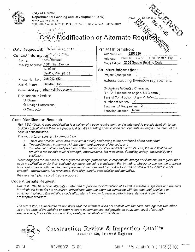
December 20, 2011 Mr. Kaveh Aminian City of Seattle Department of Planning & Development 700 Fifth Avenue, Suite 2000 Seattle, WA 98124-4019 Re: Code Modification Request, 1-Hour Wall Assembly Blakeley Manor Rehabilitation, DPD Project No. 6256329 2401 NE Blakeley Street, Seattle, WA 98105
Dear Mr. Aminian,
Please find the following information pertaining to this Code Modification Request:
Pertaining to the Description of Alternate/Modification
Blakeley Manor is an existing four-story stucco-sided apartment building operated by the
Seattle Housing Authority which will soon undergo renovation. The scope of work includes
removal of the existing stucco and lath finish and replacement with 15/32” exterior plywood for
shear, a liquid applied weather and air resistive barrier system, an exterior layer of mineral wool
for added thermal insulation, and a rainscreen siding system using cementitious lap or panel
siding over 2x4 PT furring strips. The existing wood stud framing, batt insulation, and interior
GWB remain in place unless damaged.
The replacement wall assembly was reviewed by the DPD as part of our permit set and is the
same assembly used on several other permitted SHA renovation projects: 6255337, 6256140,
and 6251153. These projects’ permits were issued under the 2006 SBC. During a courtesy field
inspection at Nelson Manor (6255337), Warren Parker labeled the assembly as “failed” because
it was not rated from both interior and exterior sides as required per 704.9, 2006 SBC - ie, it did
not have an exterior layer of GWB.
Initially we were hoping to prove this assembly’s fire resistivity from the exterior face by
calculating its fire resistance per Section 720 and sub sections of the 2006 SBC for a “Prescriptive
Fire Resistance” approach. According to Section 721.6 Wood Assemblies and Tables 721.6.2(1),
721.6.2(2) and 721.6.2(5) our proposed assembly would be allowed the following cumulative
fire resistance ratings for the individual components:
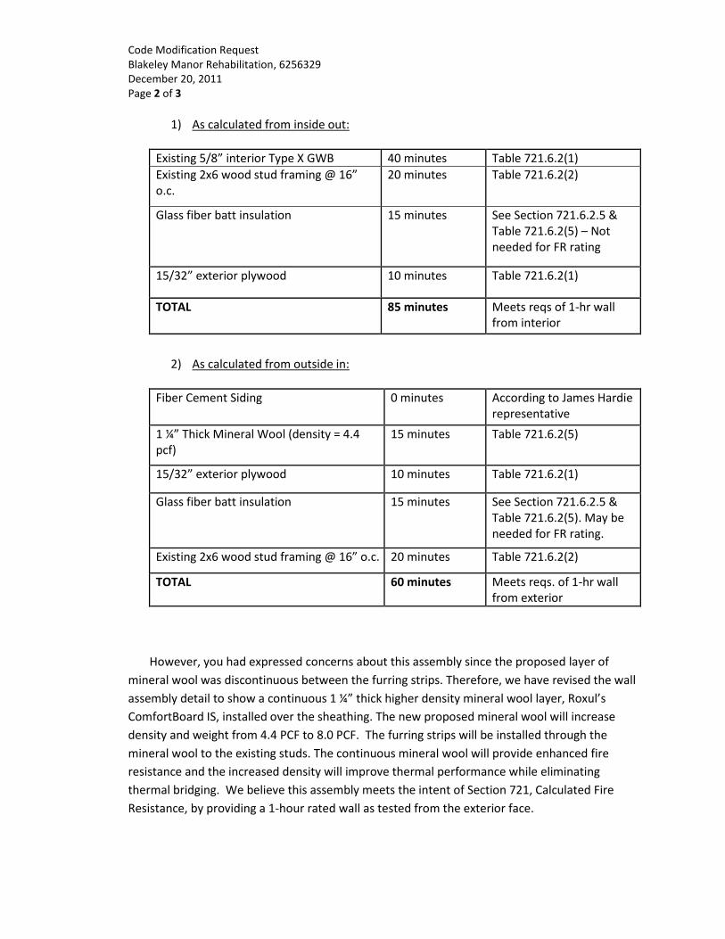
Code Modification Request Blakeley Manor Rehabilitation, 6256329 December 20, 2011 Page 2 of 3
1) As calculated from inside out:
Existing 5/8” interior Type X GWB 40 minutes Table 721.6.2(1)
Existing 2x6 wood stud framing @ 16” o.c.
20 minutes Table 721.6.2(2)
Glass fiber batt insulation 15 minutes See Section 721.6.2.5 & Table 721.6.2(5) – Not needed for FR rating
15/32” exterior plywood 10 minutes Table 721.6.2(1)
TOTAL 85 minutes Meets reqs of 1-hr wall from interior
2) As calculated from outside in:
Fiber Cement Siding 0 minutes According to James Hardie representative
1 ¼” Thick Mineral Wool (density = 4.4 pcf)
15 minutes Table 721.6.2(5)
15/32” exterior plywood 10 minutes Table 721.6.2(1)
Glass fiber batt insulation 15 minutes See Section 721.6.2.5 & Table 721.6.2(5). May be needed for FR rating.
Existing 2x6 wood stud framing @ 16” o.c. 20 minutes Table 721.6.2(2)
TOTAL 60 minutes Meets reqs. of 1-hr wall from exterior
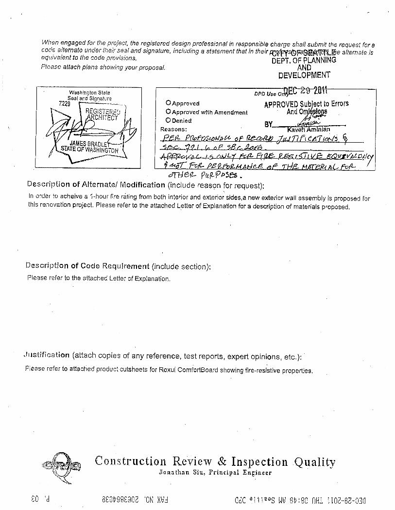
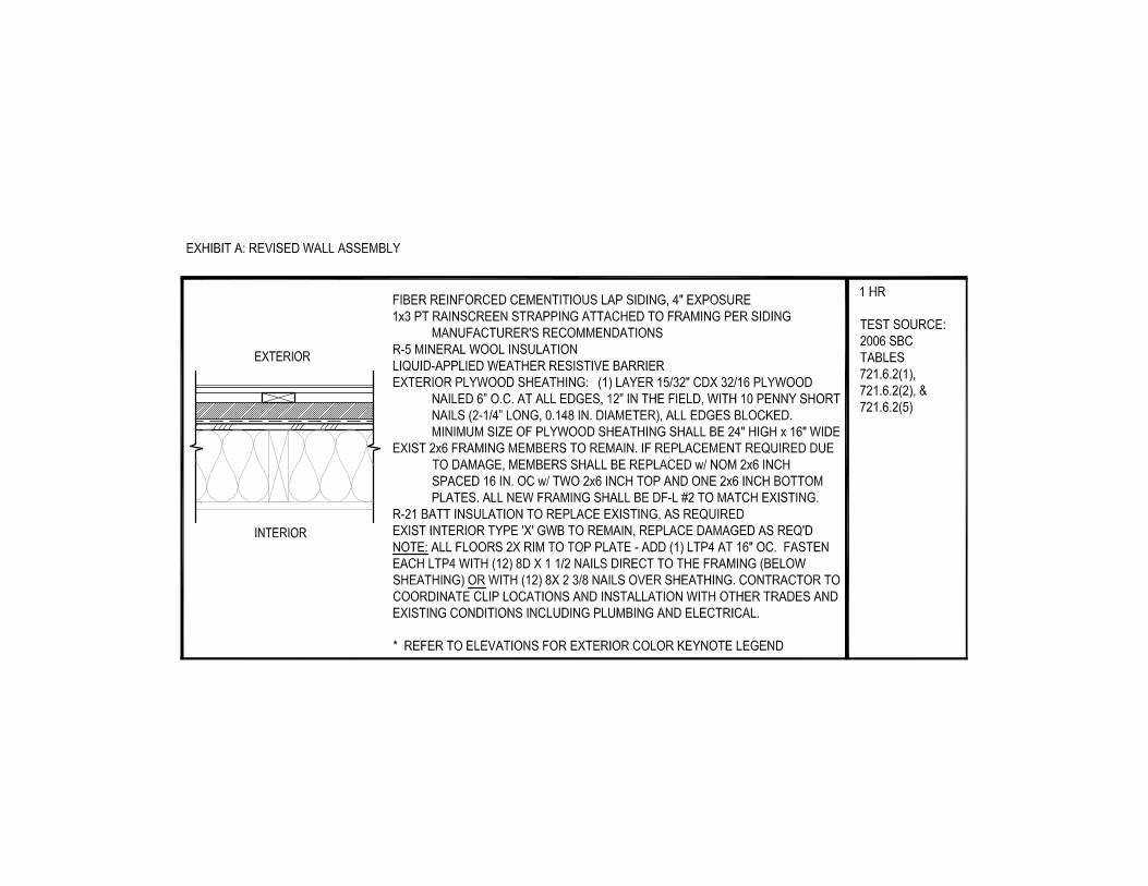
However, you had expressed concerns about this assembly since the proposed layer of
mineral wool was discontinuous between the furring strips. Therefore, we have revised the wall
assembly detail to show a continuous 1 ¼” thick higher density mineral wool layer, Roxul’s
ComfortBoard IS, installed over the sheathing. The new proposed mineral wool will increase
density and weight from 4.4 PCF to 8.0 PCF. The furring strips will be installed through the
mineral wool to the existing studs. The continuous mineral wool will provide enhanced fire
resistance and the increased density will improve thermal performance while eliminating
thermal bridging. We believe this assembly meets the intent of Section 721, Calculated Fire
Resistance, by providing a 1-hour rated wall as tested from the exterior face.
Code Modification Request Blakeley Manor Rehabilitation, 6256329 December 20, 2011 Page 3 of 3
Enclosed with this document is a cut-sheet of Roxul’s ComfortBoard IS product, the mineral
wool we prefer to use. Also please find a detail of the revised, proposed wall assembly.
It is my professional opinion that the proposed wall assembly code modification for Blakeley
Manor meets the intent of the 2006 Seattle Building Code. This opinion is true and sound to my
best information, knowledge, and belief.
Sincerely,
GGLO, LLC James Bradley, AIA Principal Att: Exhibit A – Revised Wall Assembly Exhibit B – Roxul ComfortBoard IS Technical Data
Exhibit C – Roxul Deflection Test Report
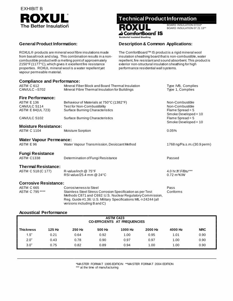
Technical Product Information
BOARD INSULATION 07210*
BOARD INSULATION 07 21 13**
General Product Information:
Description & Common Applications: ROXUL® products are mineral wool fibre insulations made from basalt rock and slag. This combination results in a non-combustible product with a melting point of approximately 2150°F (1177°C), which gives it excellent fire resistance properties. ROXUL mineral wool is a water repellent yet vapour permeable material.
The ComfortBoard™ IS product is a rigid mineral wool insulation sheathing board that is non-combustible, water repellent, fire resistant and sound absorbent. This product is exterior non-structural insulation sheathing for high performance residential wall systems.
Compliance and Performance: ASTM C 612 Mineral Fiber Block and Board Thermal Insulation Type IVB, Complies CAN/ULC –S702
Mineral Fibre Thermal Insulation for Buildings
Type 1, Complies
Fire Performance:
ASTM E 136 Behaviour of Materials at 750°C (1382°F) Non-Combustible CAN/ULC S114 Test for Non-Combustibility Non-Combustible ASTM E 84(UL 723) Surface Burning Characteristics Flame Spread = 5 Smoke Developed = 10 CAN/ULC S102 Surface Burning Characteristics Flame Spread = 5 Smoke Developed = 10
Moisture Resistance:
ASTM C 1104 Moisture Sorption 0.05%
Water Vapour Permeance:
ASTM E 96 Fungi Resistance
Water Vapour Transmission, Desiccant Method 1768 ng/Pa.s.m2 (30.9 perm)
ASTM C1338 Determination of Fungi Resistance Passed
Thermal Resistance:
ASTM C 518 (C 177) R-value/inch @ 75°F 4.0 hr.ft².F/Btu*** RSI value/25.4 mm @ 24°C 0.72 m²K/W
Corrosive Resistance:
ASTM C 665 Corrosiveness to Steel Pass ASTM C 795 **** Stainless Steel Stress Corrosion Specification as per Test
Methods C871 and C692: U.S. Nuclear Regulatory Commission, Reg. Guide #1.36: U.S. Military Specifications MIL-I-24244 (all versions including B and C)
Conforms
Acoustical Performance
ASTM C423 CO-EFFICIENTS AT FREQUENCIES
Thickness 125 Hz 250 Hz 500 Hz 1000 Hz 2000 Hz 4000 Hz NRC
1.5” 0.21 0.64 0.92 1.00 0.95 1.01 0.90
2.0” 0.43 0.78 0.90 0.97 0.97 1.00 0.90
3.0” 0.75 0.82 0.89 0.94 1.00 1.00 0.90
*MASTER FORMAT 1995 EDITION **MASTER FORMAT 2004 EDITION *** at the time of manufacturing
EXHIBIT B
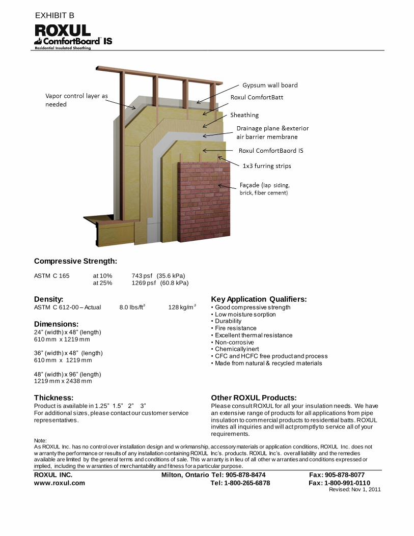
Compressive Strength:
ASTM C 165 at 10% 743 psf (35.6 kPa) at 25% 1269 psf (60.8 kPa)
Density:
Key Application Qualifiers: • Good compressive strength • Low moisture sorption • Durability • Fire resistance • Excellent thermal resistance • Non-corrosive • Chemically inert • CFC and HCFC free product and process • Made from natural & recycled materials
ASTM C 612-00 – Actual 8.0 lbs/ft3 128 kg/m
3
Dimensions: 24” (width) x 48” (length) 610 mm x 1219 mm 36” (width) x 48” (length) 610 mm x 1219 mm 48” (width) x 96” (length) 1219 mm x 2438 mm
Thickness: Other ROXUL Products: Product is available in 1.25” 1.5” 2” 3” For additional sizes, please contact our customer service representatives.
Please consult ROXUL for all your insulation needs. We have an extensive range of products for all applications from pipe insulation to commercial products to residential batts. ROXUL invites all inquiries and will act promptly to service all of your requirements.
Note: As ROXUL Inc. has no control over installation design and w orkmanship, accessory materials or application conditions, ROXUL Inc. does not
w arranty the performance or results of any installation containing ROXUL Inc’s. products. ROXUL Inc’s. overall liability and the remedies available are limited by the general terms and conditions of sale. This w arranty is in lieu of all other w arranties and conditions expressed or
implied, including the w arranties of merchantability and f itness for a particular purpose.
ROXUL INC. Milton, Ontario Tel: 905-878-8474 Fax: 905-878-8077
www.roxul.com Tel: 1-800-265-6878 Fax: 1-800-991-0110 Revised: Nov 1, 2011
EXHIBIT B
Building Science Consulting Inc. P: 519.342.4731 1 167 Lexington Court, Unit 5 Waterloo, Ontario, N2J 4R9 www.buildingscience.com 9
March 3, 2011
Mark Bromiley Roxul Inc. 420 Bronte St. S. Suite 105 Milton, Ontario, L9T 0H9
Via email: [email protected]
Re: Roxul – Exterior Insulation Deflection Testing
Background As society demands more energy efficient buildings, codes and builders are responding by increasing the R-value of the building enclosure, in particular the above-grade wall. Given than the cavity of the standard 2x6 wood frame wall used in low-rise housing is already filled with insulation, the clear path forward to higher R-values is to add layers of exterior insulation. Although other solutions are possible, exterior insulation layers have the benefits that:
1. At thicknesses of up to 1.5”, exterior insulation has long been used by the industry, and hence there is experience with it installation and detailing,
2. Thermal bridging through framing members, floor joists, lintels, etc. is very significantly reduced, increasing the wall R-value significantly,
3. The risk of cold-weather condensation within the moisture-vulnerable wood framing is significantly reduced, and potentially eliminated,
4. A range of target R-values can be easily reached as similar details can be used for the design of walls that have 2, 3, 4 or even 6” of insulation,
5. The marginal cost of increasing framing thickness and/or building double-walls usually outweighs the marginal cost of adding insulating sheathing layers.
Highly-permeable insulation like Roxul has the added benefit that it allows very fast outward drying during cold weather: this dries the wood-frame cavity very quickly, even if the framing is wet from construction or becomes wet because of incidental water leaks.
A major impediment to the wide-spread adoption of exterior sheathing behind direct applied claddings such as vinyl, wood, fibre cement, stucco and adhered veneer, is the lack of information about the structural performance of claddings installed over insulating sheathing. Foam plastic insulations, which have much higher compressive strengths (often 15 to 25 psi @10% deformation) than most Roxul products (often 1 to 5 psi) are seen as better products for this application. The concern is that the insulation is not or stiff strong enough to suspend claddings and deformations may occur causing cracking, and other issues.
EXHIBIT C
Roxul – Exterior Insulation Deflection Testing – February 2011
Building Science Consulting Inc. P: 519.342.4731 2 167 Lexington Court, Unit 5 Waterloo, Ontario, N2J 4R9 www.buildingscience.com 9
Very little testing has been conducted to show the strength and stiffness of insulation supporting cladding and no testing results of Roxul insulation is available.
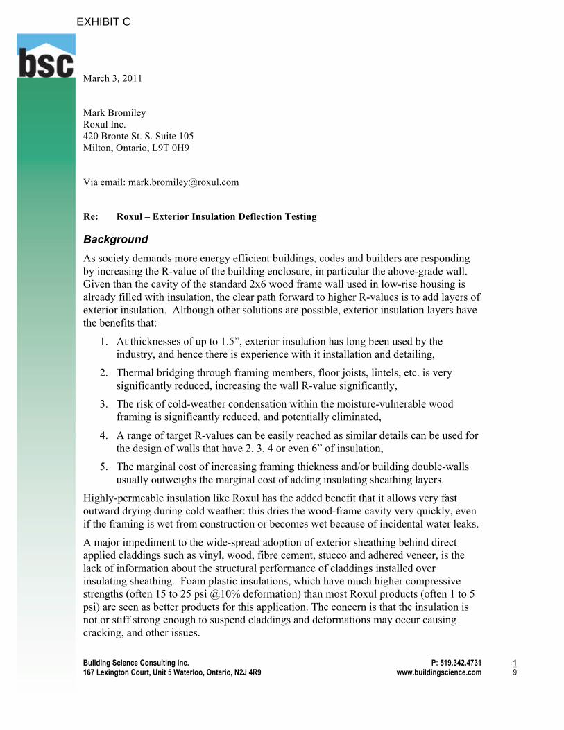
The most common method of attaching cladding over thick insulation is to use wood furring (strapping) attached with screws through the insulation to the framing as shown in Figure 1.
Figure 1: Typical application of semi-rigid Roxul insulation over wood framing
Objective The objective of this study is to quantify the relationship between cladding gravity loads and deflection under cladding weights of up to 30 pound per square foot. These results are intended to be used to provide guidance to designers, builders, and code officials involved in projects using Roxul brand semi-rigid rockwool sheathing.
Scope This report summarizes the results of load deflection testing deflection of strapping over six types of Roxul exterior insulation as shown in Table 1. These walls were tested on 24” oc framing, with strapping attachment screws at vertical spacings of 16” oc. Other variables such as 16” oc framing, different screw sizes and spacings were outside the
EXHIBIT C
Roxul – Exterior Insulation Deflection Testing – February 2011
Building Science Consulting Inc. P: 519.342.4731 3 167 Lexington Court, Unit 5 Waterloo, Ontario, N2J 4R9 www.buildingscience.com 9
scope of the testing program. This study was designed to simulate walls providing the least support practically likely (thin screws wide spacing of studs and fasteners) and hence the highest likely deflections. If improved construction standards are used, such as stronger screws and/or more frequent screw spacing, the amount of deflection would decrease. This is meant to be a type of worst case, yet realistic, scenario.
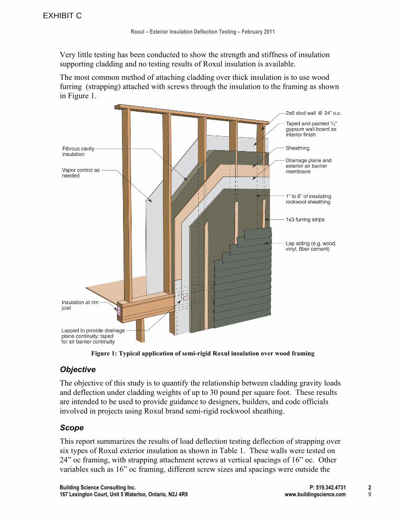
Table 1: Roxul insulation types to be tested
Insulation Product Approximate Density (lb/ft3)
1.25” Cavity Rock MonoDensity 4.1
3” Cavity Rock DualDensity 3.4 / 6.2
1.25” RB60 6.0
1.25” RB80 8.0
3” RB80 8.0
1.25” Drainboard 8.0
1” Type IV extruded polystyrene 2.0
Testing Apparatus To conduct the testing, a 2x wall frame with 24” stud spacing was securely fastened to a concrete block wall in the laboratory. OSB sheathing and a house wrap were installed over the sheathing. The different types of Roxul insulation were installed over the house wrap, and held in place by screws driven through nominal 1x3 strapping (actual dimension !”x 2.5”) connected directly to the wood framing (Figure 2). The strapping was attached with screws spaced vertically at 16” oc. Given the 24” spacing of the framing, this is 2.67 square feet per fastener (or about 4 connectors per square meter).
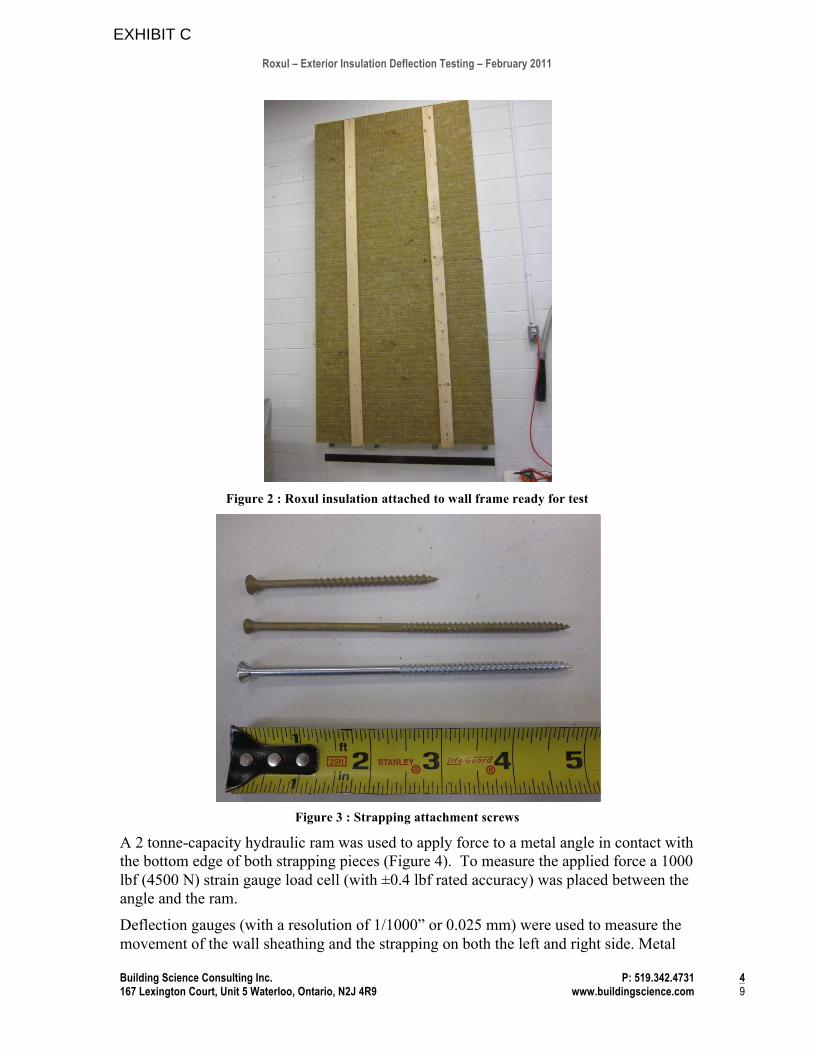
Figure 3 presents photographs of the screws used for strapping attachment for both 1.25” thick insulation and 3” thick insulation. To attach strapping over 1.25” thick insulation, 3” deck screws were used. For the first tests the strapping over 3” thick insulation was attached using #9 x 5” trim head bronze wood screws were used (middle screw in Figure 3). After inspection of the screws following the first test, this screw showed considerable permanent deflection, and the smaller diameter heads pulled deep into the wood of the furring strip. Hence, subsequent test of 3” thick insulation used #10 x 5” wood screws with standard head sizes. These screws showed a marked improvement in performance.
EXHIBIT C
Roxul – Exterior Insulation Deflection Testing – February 2011
Building Science Consulting Inc. P: 519.342.4731 4 167 Lexington Court, Unit 5 Waterloo, Ontario, N2J 4R9 www.buildingscience.com 9
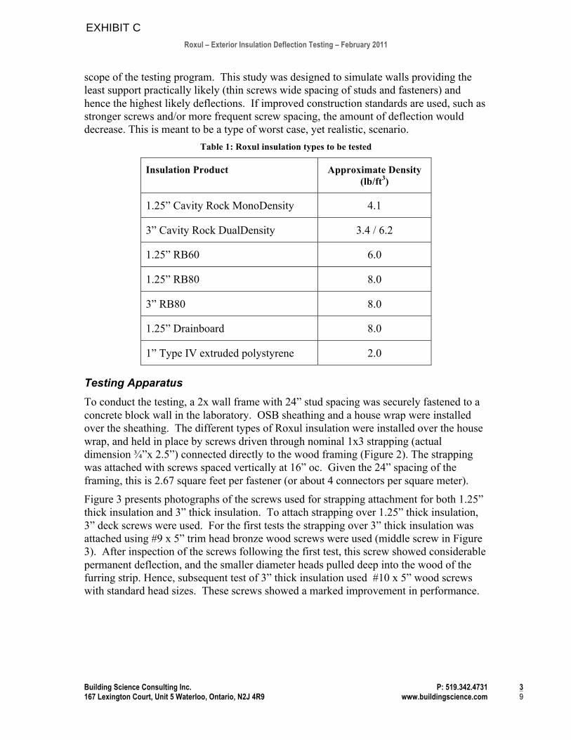
Figure 2 : Roxul insulation attached to wall frame ready for test
Figure 3 : Strapping attachment screws
A 2 tonne-capacity hydraulic ram was used to apply force to a metal angle in contact with the bottom edge of both strapping pieces (Figure 4). To measure the applied force a 1000 lbf (4500 N) strain gauge load cell (with ±0.4 lbf rated accuracy) was placed between the angle and the ram.
Deflection gauges (with a resolution of 1/1000” or 0.025 mm) were used to measure the movement of the wall sheathing and the strapping on both the left and right side. Metal
EXHIBIT C
Roxul – Exterior Insulation Deflection Testing – February 2011
Building Science Consulting Inc. P: 519.342.4731 5 167 Lexington Court, Unit 5 Waterloo, Ontario, N2J 4R9 www.buildingscience.com 9
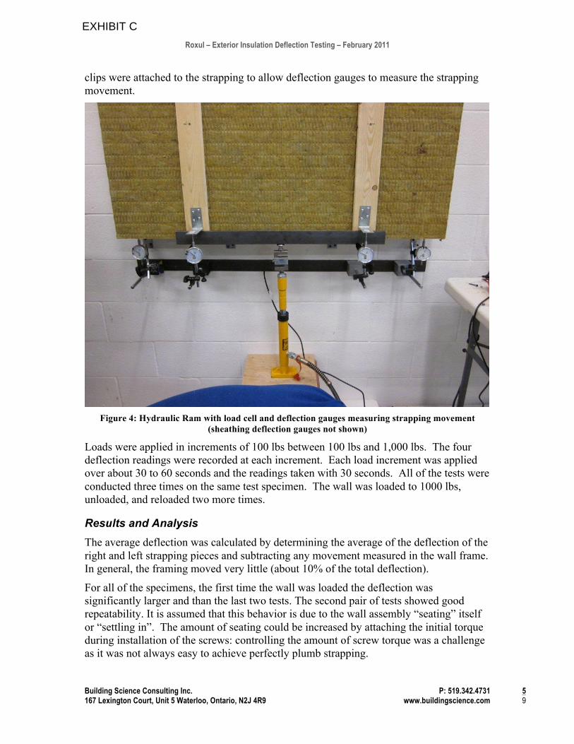
clips were attached to the strapping to allow deflection gauges to measure the strapping movement.
Figure 4: Hydraulic Ram with load cell and deflection gauges measuring strapping movement
(sheathing deflection gauges not shown)
Loads were applied in increments of 100 lbs between 100 lbs and 1,000 lbs. The four deflection readings were recorded at each increment. Each load increment was applied over about 30 to 60 seconds and the readings taken with 30 seconds. All of the tests were conducted three times on the same test specimen. The wall was loaded to 1000 lbs, unloaded, and reloaded two more times.
Results and Analysis The average deflection was calculated by determining the average of the deflection of the right and left strapping pieces and subtracting any movement measured in the wall frame. In general, the framing moved very little (about 10% of the total deflection).
For all of the specimens, the first time the wall was loaded the deflection was significantly larger and than the last two tests. The second pair of tests showed good repeatability. It is assumed that this behavior is due to the wall assembly “seating” itself or “settling in”. The amount of seating could be increased by attaching the initial torque during installation of the screws: controlling the amount of screw torque was a challenge as it was not always easy to achieve perfectly plumb strapping.
EXHIBIT C
Roxul – Exterior Insulation Deflection Testing – February 2011
Building Science Consulting Inc. P: 519.342.4731 6 167 Lexington Court, Unit 5 Waterloo, Ontario, N2J 4R9 www.buildingscience.com 9
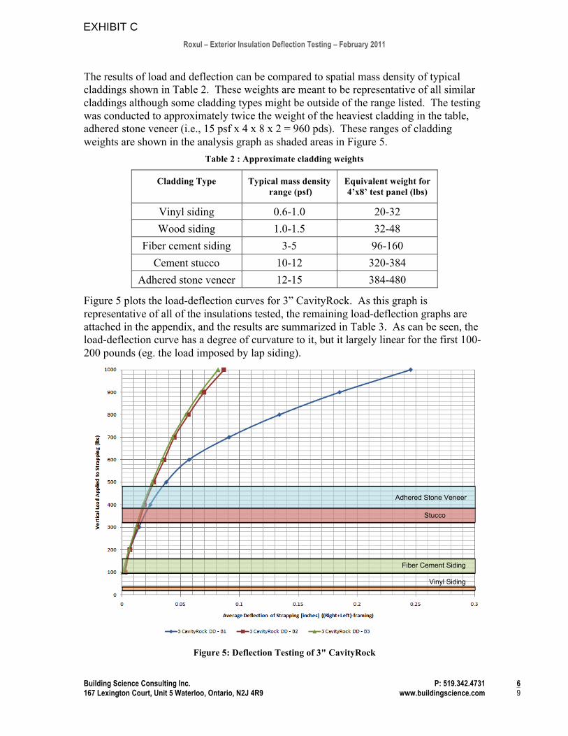
The results of load and deflection can be compared to spatial mass density of typical claddings shown in Table 2. These weights are meant to be representative of all similar claddings although some cladding types might be outside of the range listed. The testing was conducted to approximately twice the weight of the heaviest cladding in the table, adhered stone veneer (i.e., 15 psf x 4 x 8 x 2 = 960 pds). These ranges of cladding weights are shown in the analysis graph as shaded areas in Figure 5.
Table 2 : Approximate cladding weights
Cladding Type Typical mass density range (psf)
Equivalent weight for 4’x8’ test panel (lbs)
Vinyl siding 0.6-1.0 20-32 Wood siding 1.0-1.5 32-48
Fiber cement siding 3-5 96-160 Cement stucco 10-12 320-384
Adhered stone veneer 12-15 384-480
Figure 5 plots the load-deflection curves for 3” CavityRock. As this graph is representative of all of the insulations tested, the remaining load-deflection graphs are attached in the appendix, and the results are summarized in Table 3. As can be seen, the load-deflection curve has a degree of curvature to it, but it largely linear for the first 100-200 pounds (eg. the load imposed by lap siding).
Figure 5: Deflection Testing of 3" CavityRock
Adhered Stone Veneer
Stucco
Fiber Cement Siding
Vinyl Siding
EXHIBIT C
Roxul – Exterior Insulation Deflection Testing – February 2011
Building Science Consulting Inc. P: 519.342.4731 7 167 Lexington Court, Unit 5 Waterloo, Ontario, N2J 4R9 www.buildingscience.com 9
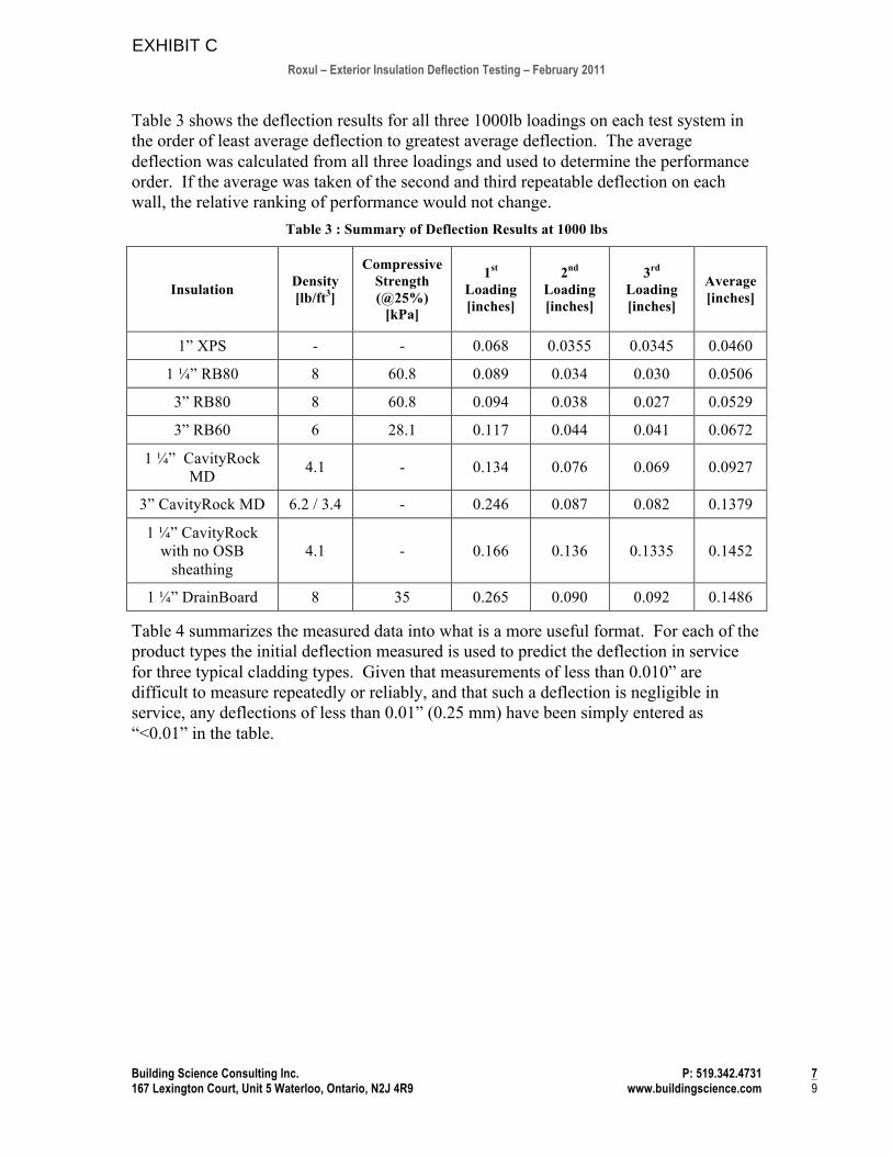
Table 3 shows the deflection results for all three 1000lb loadings on each test system in the order of least average deflection to greatest average deflection. The average deflection was calculated from all three loadings and used to determine the performance order. If the average was taken of the second and third repeatable deflection on each wall, the relative ranking of performance would not change.
Table 3 : Summary of Deflection Results at 1000 lbs
Insulation Density [lb/ft3]
Compressive Strength (@25%)
[kPa]
1st Loading [inches]
2nd Loading [inches]
3rd Loading [inches]
Average [inches]
1” XPS - - 0.068 0.0355 0.0345 0.0460
1 "” RB80 8 60.8 0.089 0.034 0.030 0.0506
3” RB80 8 60.8 0.094 0.038 0.027 0.0529
3” RB60 6 28.1 0.117 0.044 0.041 0.0672
1 "” CavityRock MD 4.1 - 0.134 0.076 0.069 0.0927
3” CavityRock MD 6.2 / 3.4 - 0.246 0.087 0.082 0.1379
1 "” CavityRock with no OSB
sheathing 4.1 - 0.166 0.136 0.1335 0.1452
1 "” DrainBoard 8 35 0.265 0.090 0.092 0.1486
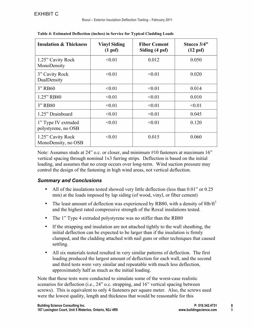
Table 4 summarizes the measured data into what is a more useful format. For each of the product types the initial deflection measured is used to predict the deflection in service for three typical cladding types. Given that measurements of less than 0.010” are difficult to measure repeatedly or reliably, and that such a deflection is negligible in service, any deflections of less than 0.01” (0.25 mm) have been simply entered as “<0.01” in the table.
EXHIBIT C
Roxul – Exterior Insulation Deflection Testing – February 2011
Building Science Consulting Inc. P: 519.342.4731 8 167 Lexington Court, Unit 5 Waterloo, Ontario, N2J 4R9 www.buildingscience.com 9
Table 4: Estimated Deflection (inches) in Service for Typical Cladding Loads
Insulation & Thickness Vinyl Siding (1 psf)
Fiber Cement Siding (4 psf)
Stucco 3/4” (12 psf)
1.25” Cavity Rock MonoDensity
<0.01 0.012 0.050
3” Cavity Rock DualDensity
<0.01 <0.01 0.020
3” RB60 <0.01 <0.01 0.014
1.25” RB80 <0.01 <0.01 0.010
3” RB80 <0.01 <0.01 <0.01
1.25” Drainboard <0.01 <0.01 0.045
1” Type IV extruded polystyrene, no OSB
<0.01 <0.01 0.120
1.25” Cavity Rock MonoDensity, no OSB
<0.01 0.015 0.060
Note: Assumes studs at 24” o.c. or closer, and minimum #10 fasteners at maximum 16” vertical spacing through nominal 1x3 furring strips. Deflection is based on the initial loading, and assumes that no creep occurs over long-term. Wind suction pressure may control the design of the fastening in high wind areas, not vertical deflection.
Summary and Conclusions
• All of the insulations tested showed very little deflection (less than 0.01” or 0.25 mm) at the loads imposed by lap siding (of wood, vinyl, or fiber cement)
• The least amount of deflection was experienced by RB80, with a density of 8lb/ft3 and the highest rated compressive strength of the Roxul insulations tested.
• The 1” Type 4 extruded polystyrene was no stiffer than the RB80
• If the strapping and insulation are not attached tightly to the wall sheathing, the initial deflection can be expected to be larger than if the insulation is firmly clamped, and the cladding attached with nail guns or other techniques that caused settling.
• All six materials tested resulted in very similar patterns of deflection. The first loading produced the largest amount of deflection for each wall, and the second and third tests were very similar and repeatable with much less deflection, approximately half as much as the initial loading.
Note that these tests were conducted to simulate some of the worst-case realistic scenarios for deflection (i.e., 24” o.c. strapping, and 16” vertical spacing between screws). This is equivalent to only 4 fasteners per square meter. Also, the screws used were the lowest quality, length and thickness that would be reasonable for this
EXHIBIT C
Roxul – Exterior Insulation Deflection Testing – February 2011
Building Science Consulting Inc. P: 519.342.4731 9 167 Lexington Court, Unit 5 Waterloo, Ontario, N2J 4R9 www.buildingscience.com 9
application. Using more screws, more often would likely decrease deflection, but more testing is required to determine the amount that the deflection could be decreased.
Recommendations It is recommended that field trials be conducted to gain feedback from installers in the field. It was noted that some care was required when installing the screws to attach the fastening so as to ensure a plumb strapping: excess or insufficient screw torque could cause the strap to be bent.
In practice, recommending screw attachments at 12” o.c for 24” o.c framing and 16” for 16” o.c framing would provide some additional safety factors.
Despite the very favourable results achieved, it is recommended that field testing, in a test facility or on a jobsite, should be conducted to assess the potential for stucco or adhered veneer cracking over a 1-2 year test period before proceeding with wider deployment.
If you have any questions or comments about any part of this report, please do not hesitate to call or email.
Sincerely
Jonathan Smegal, MASc. John Straube, Ph.D. P.Eng. Associate EIT Principal
EXHIBIT C
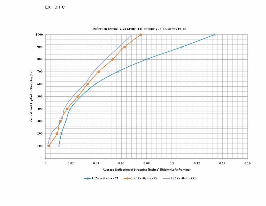
EXHIBIT C
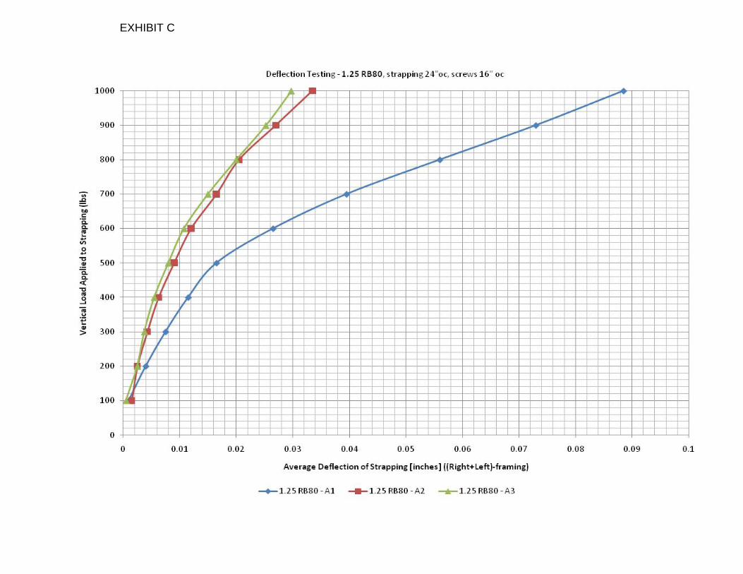
EXHIBIT C
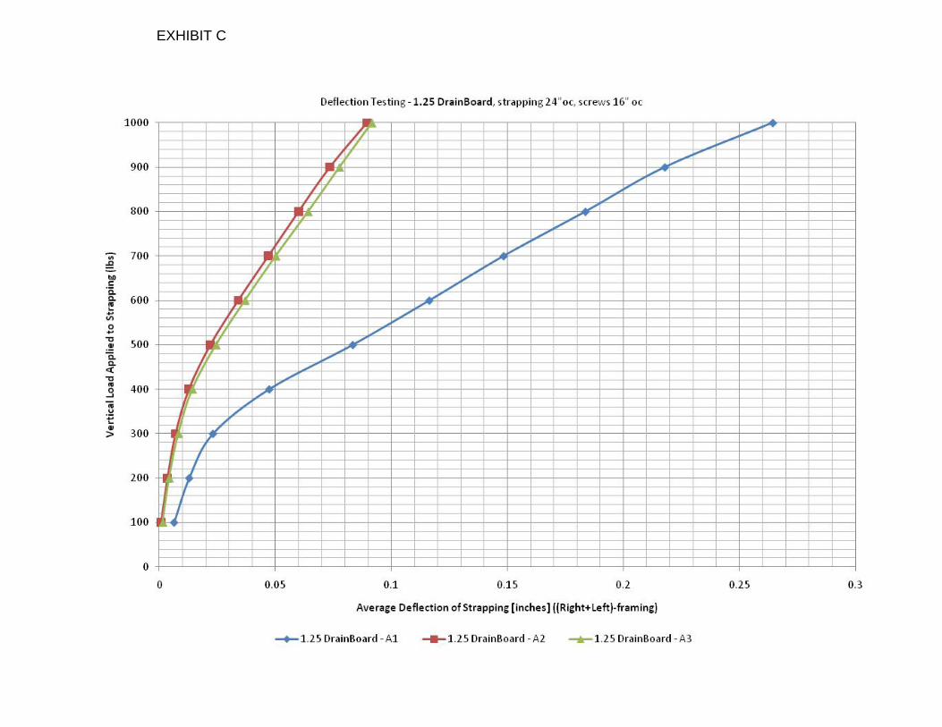
EXHIBIT C
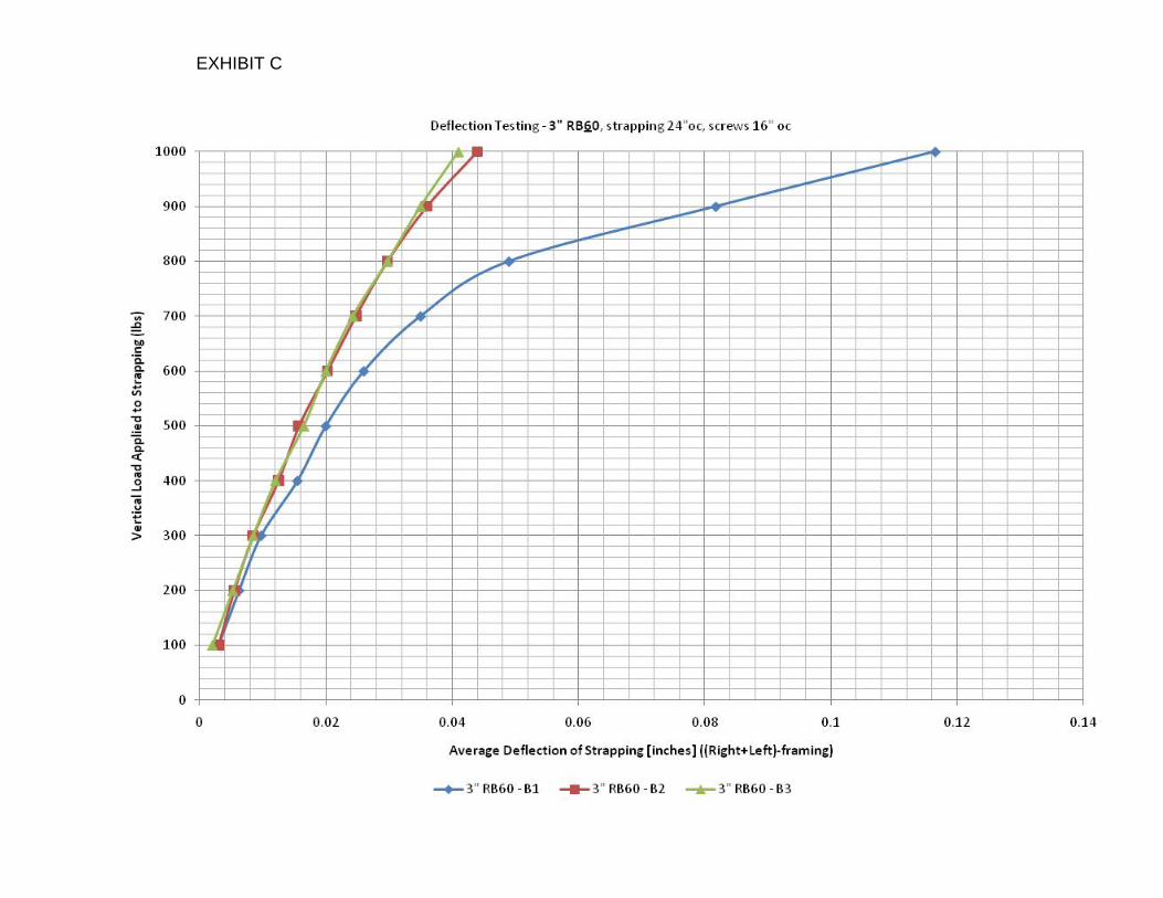
EXHIBIT C
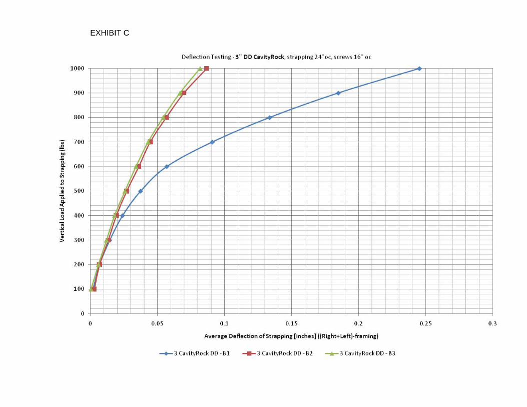
EXHIBIT C
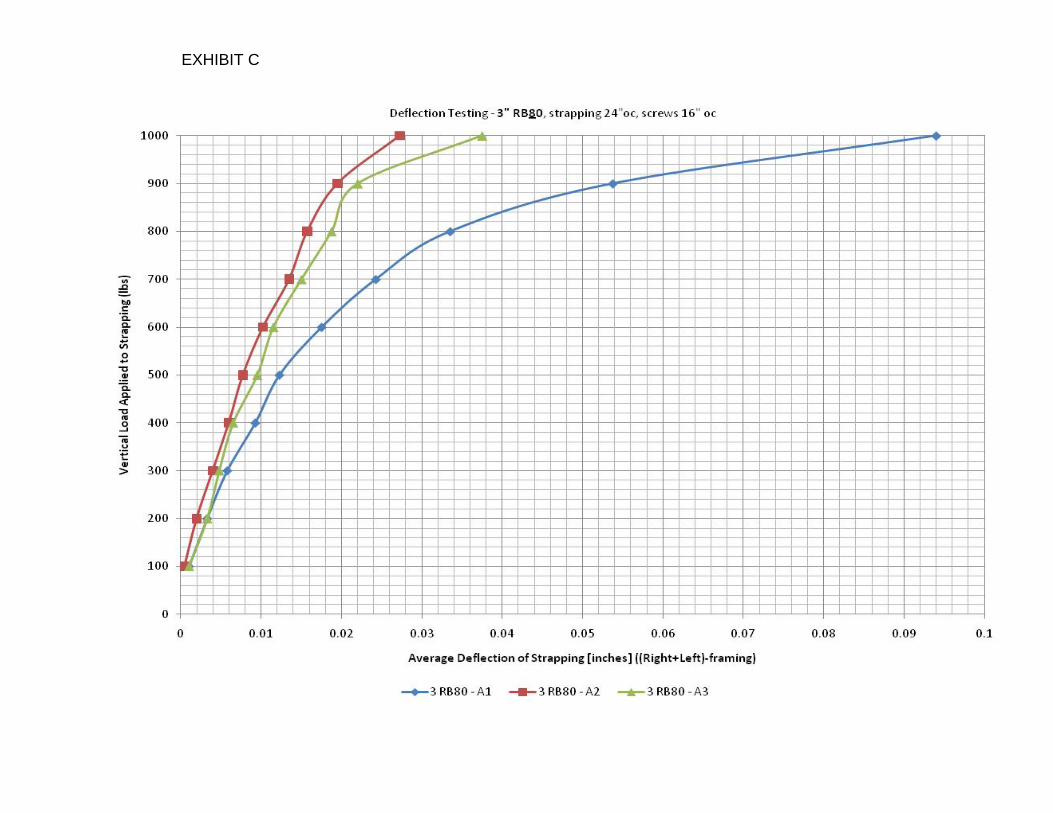
EXHIBIT C
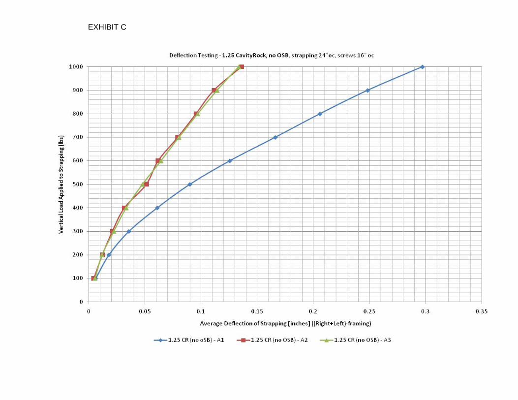
EXHIBIT C
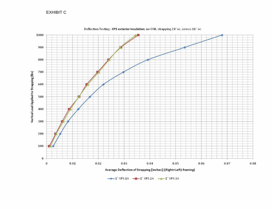
EXHIBIT C