Embed Size (px)
Citation preview

December 01, 2017 5th Street/ Independence Hall Station Enhancement Bid Set
DOOR HARDWARE 087100 - 23
Set: 4.0
Doors: 10, 10A, 12, 15, 17, 19, 2, 20, 3, 5, 7, 18A
3 Hinge TA2314 US32D MK
1 Mortise Lock (storeroom) TER3 8805RL CMK 626 YA
1 Door Closer R (or) PR7500 689 NO
1 Kick Plate K1050 10" 4BE CSK US32D RO
1 Door Stop 403 (or) 441CU US26D RO
1 Threshold 166A MSES10SS PE
1 Gasketing (head/jamb) S773BL PE
1 Sweep 315CN PE
Set: 5.0
Doors: 11, 6
3 Hinge TA2314 US32D MK
1 Mortise Lock (privacy lock) TER3 8862RL IND 626 YA
1 Door Closer R (or) PR7500 689 NO
2 Kick Plate K1050 10" 4BE CSK US32D RO
1 Door Stop 403 (or) 441CU US26D RO
1 Threshold 166A MSES10SS PE
1 Gasketing (head/jamb) S773BL PE
1 Sweep 315CN PE
Set: 6.0
Doors: 1A
3 Hinge TA2314 US32D MK
1 Mortise Lock (storeroom) TER3 8805RL CMK 626 YA
1 Door Closer CLP7500 689 NO
1 Kick Plate K1050 10" 4BE CSK US32D RO
3 Silencer 608 (or) 609 RO
Set: 7.0 Doors: 13A, 4A
6 Hinge TA2314 US32D MK
1 Dust Proof Strike 570 US26D RO
43-1-2018

March 2018 5th Street/Independence Hall Station Enhancement Addendum 4
Audio/Visual Public Announcement Systems 16830-1
SECTION 16830
AUDIO/VISUAL PUBLIC ANNOUNCEMENT SYSTEMS
PART 1 - GENERAL
1.01 STIPULATIONS
A. Project drawings and general provisions of the Contract, including but not limited to all; General and Supplementary Conditions, Division 01 Specification Sections and stipulated Specification Sections shall apply to this and all related Division 16 specification sections.
B. Related Specification Sections:
1. In addition to the above requirements the following Specification Sections shall also apply to this Section:
a. Division 07 – Through-penetration Firestop Systems b. Division 16, Section “Basic Electrical Requirements.” c. Division 16, Section “Conductors and Cables.” d. Division 16, Section “Grounding and Bonding.” e. Division 16, Section “Hangers and Supports.” f. Division 16, Section “Raceways and Boxes.” g. Division 16, Section “Electrical Identification.” h. Division 16, Section “Common Work Results For
Communications Systems” i. Division 16, Section “Common Work Results for Safety and
Security Systems.”
1.02 SUMMARY
A. Work Includes:
1. Provide a complete and fully operational audio/visual public address (AVPA) system consisting of computers, software, public address systems, variable message signs and communications equipment to comply with the Americans With Disabilities Act (ADA). The system will provide and intelligent, synchronized messaging system to the passengers. The messages will include schedule, emergency, service, boarding, safety, and other types of information.
2. The Contractor shall provide Variable Message Signs (VMS), Station Control Units/computers (SCU), Public Address (PA)

March 2018 5th Street/Independence Hall Station Enhancement Addendum 4
Audio/Visual Public Announcement Systems 16830-2
speakers and microphones, and related sub-systems at each station as shown on the SEPTA approved Drawings.
3. The Contractor shall provide the communications protocols for the VMS and PA Systems for integration into the AVPA System. The protocols provided shall include individual messages for control of the signs for programming, diagnosis, storage and access. This information shall be submitted to SEPTA for approval prior to purchasing any actual hardware.
4. The Contractor shall furnish and install:
a. Variable Message Signs (VMS) as shown on the Contract Drawings.
b. PA system speakers as shown on the Contract Drawings and a microphone (Platform Microphone) located in a NEMA approved box mounted on the exterior of the station building. (To be field located prior to installation)
c. Station Control Unit (SCU) located in a NEMA approved box with the microphone.
d. All wire and cable subsystems required for a full installation. e. All electrical subsystems required for a full installation. f. Modified Control Center AVPA Workstation applications as
specified herein. g. The latest supported software upgrade to configure and
operate the system. SCU computer software shall be GEisys, Daktronics MetroDVS or SEPTA approved 100 percent compatible software. The Contractor shall purchase any software licenses required.
h. The Contractor shall supply all cabinets and enclosures (Mechanical Room Cabinet and Platform Box) to be NEMA approved as well as all mounting and support hardware. Provide final breaker / panel information in AVPA cabinet.
5. The Contractor, in coordination with SEPTA shall integrate and test all systems and components.
6. The Contractor, in coordination with SEPTA shall record, digitize and add to the new audio database all words and phrases required for the new stations and systems. SEPTA will provide the list of words and phrases along with the person whose voice is to be used. The Contractor shall record this information and add to the new databases as necessary. All messages are generated from a single source to provide a consistent presentation to the passengers. All modified or new audio recordings shall be consistent with the existing system.

March 2018 5th Street/Independence Hall Station Enhancement Addendum 4
Audio/Visual Public Announcement Systems 16830-3
7. The Contractor shall provide training on maintenance, configuration, operation and administration of the systems. Training shall be concentrated on hardware, software and operational modifications.
1.03 DEFINITIONS
A. Channels: Separate parallel signal paths, from sources to loudspeakers or loudspeaker zones, with separate amplification and switching that permit selection between paths for speaker alternative program signals.
B. VU: Volume unit.
C. Zone: Separate group of loudspeakers and associated supply wiring that may be arranged for selective switching between different channels.
1.04 SUBMITTALS
A. Submittals shall be required for each product as specified herein and included in the following stages:
1. Supply complete bill of materials; supply a listing of all audio and electronic test equipment as specified herein; supply a listing of the personnel with their qualifications as in the section QUALITY ASSURANCE above.
2. The Contractor shall submit drawings and documentation as specified under section SHOP DRAWINGS above including the following drawings:
a. Technical data sheets, catalog cuts, and specifications for all
equipment proposed to be provided. b. Riser diagrams, showing all elevations; room numbers;
conduit sizes, types, and fill; box sizes; device type and location; device mounting details; and equipment and rack designations.
c. Cable run sheets indicating each and every connection in the system, including cable designation, cable type, manufacturer model number, conductor color, device connector, and designation, and device location, keyed to both system and equipment racks.
d. Comprehensive, single-line diagrams, including all equipment, devices, and cabling completely identified.
e. Complete equipment rack elevation drawings.
B. When submitting a request for substitution or deviation, include:

March 2018 5th Street/Independence Hall Station Enhancement Addendum 4
Audio/Visual Public Announcement Systems 16830-4
1. A written description of the total foreseeable effect of the substitution or deviation upon the design of the Project and agree to be directly responsible for any resultant extra costs.
2. All information as pursuant with Part 2 of this section.
C. All costs associated with independent testing or documentation as may be required by the Owner shall be the sole responsibility of the Contractor. Acceptance of substitutions by the Owner does not endorse the substitution. The Contractor is responsible for the performance or effect the substitution may have upon the system and or its component parts.
D. The Owner may elect to have the Contractor setup an A/B test of the specified and proposed substitution for both objective and subjective testing and comparison. All of these tests shall be done through the coordination of the Owner and any and all costs shall be totally borne by the Contractor without any charge to the Owner and shall not interfere with the Progress Schedule of the Work.
E. The Contractor shall not order any material until the materials list is accepted.
F. The Contractor shall not proceed with the installation until all submittals are accepted.
G. The Contractor shall be directly responsible for any costs incurred by the Consultant as a result of substitution testing for time, travel, and expenses
1.05 QUALITY ASSURANCE
A. Installer Qualifications: Contractor shall be a Manufacturer's authorized representative and have at least two (2) years direct experience with devices, equipment, and systems of the type and scope specified herein. The Contractor shall be a business entity that is substantially engaged in the work of this section and has successfully done so for the past three consecutive years at a minimum. The Contractor shall as part of the foregoing business have a fully staffed, parts stocked, and equipped maintenance and repair facility within two (2) hours traveling-time of the jobsite during normal business-traffic conditions. Personnel performing the work shall be certified by NICET as Audio System Technicians.
B. Testing Agency Qualifications: Qualified agency, with the experience and capability to conduct testing indicated.
1. Testing Agency's Field Supervisor: Currently certified by NICET at Level III to supervise on-site testing.
March 2018 5th Street/Independence Hall Station Enhancement Addendum 4
Audio/Visual Public Announcement Systems 16830-5
C. Source Limitations: Obtain public address and mass notification systems from single source from single manufacturer.
D. Electrical Components, Devices, and Accessories: Listed and labeled as defined in NFPA 70, by a qualified testing agency, and marked for intended location and application.
E. Comply with NFPA 70.
1.06 COORDINATION
A. Coordinate layout and installation of system components and suspension system with other construction that penetrates ceilings or is supported by them, including light fixtures, HVAC equipment, fire-suppression system, and partition assemblies.
B. All the Work included in this Section shall be coordinated with the current operation of the existing SEPTA AVPA system.
C. The Contractor shall coordinate the finish required for all fixtures, plates, panels, grilles, and enclosures supplied as part of this section with SEPTA Manager.
D. The Contractor shall be responsible for coordination with the Millworker for any AVPA items to be built or mounted into millwork.
E. Prior to installing the SCUs within the station Communications Rooms, the Contractor shall coordinate with SEPTA and deliver the SCUs to SEPTA for initial software configuration and setup. Upon completion of the setup by SEPTA, the SCUs will be returned to the Contractor for installation.
PART 2 - PRODUCTS
2.01 ACCEPTABLE PROVIDER, INSTALLER
A. The Contractor shall purchase all required AVP PA licenses to complete the project. AVPA License provider Contact: GE Intelligent Transportation Solutions Richard Bennett, Sales Leader 2712 S. Dillingham, Grain Valley MO 64029 Phone: (816) 650-4437 Cell Phone: (816) 729-2898 Fax (816) 817-1834
March 2018 5th Street/Independence Hall Station Enhancement Addendum 4
Audio/Visual Public Announcement Systems 16830-6
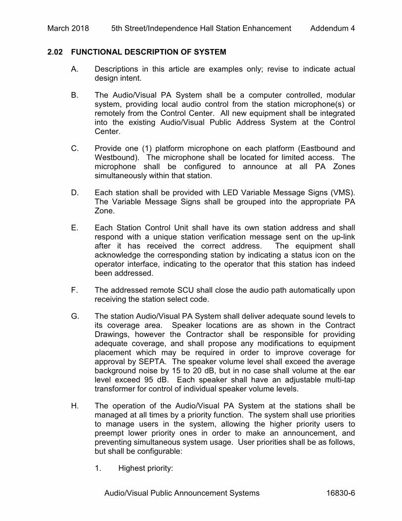
2.02 FUNCTIONAL DESCRIPTION OF SYSTEM
A. Descriptions in this article are examples only; revise to indicate actual design intent.
B. The Audio/Visual PA System shall be a computer controlled, modular system, providing local audio control from the station microphone(s) or remotely from the Control Center. All new equipment shall be integrated into the existing Audio/Visual Public Address System at the Control Center.
C. Provide one (1) platform microphone on each platform (Eastbound and Westbound). The microphone shall be located for limited access. The microphone shall be configured to announce at all PA Zones simultaneously within that station.
D. Each station shall be provided with LED Variable Message Signs (VMS). The Variable Message Signs shall be grouped into the appropriate PA Zone.
E. Each Station Control Unit shall have its own station address and shall respond with a unique station verification message sent on the up-link after it has received the correct address. The equipment shall acknowledge the corresponding station by indicating a status icon on the operator interface, indicating to the operator that this station has indeed been addressed.
F. The addressed remote SCU shall close the audio path automatically upon receiving the station select code.
G. The station Audio/Visual PA System shall deliver adequate sound levels to its coverage area. Speaker locations are as shown in the Contract Drawings, however the Contractor shall be responsible for providing adequate coverage, and shall propose any modifications to equipment placement which may be required in order to improve coverage for approval by SEPTA. The speaker volume level shall exceed the average background noise by 15 to 20 dB, but in no case shall volume at the ear level exceed 95 dB. Each speaker shall have an adjustable multi-tap transformer for control of individual speaker volume levels.
H. The operation of the Audio/Visual PA System at the stations shall be managed at all times by a priority function. The system shall use priorities to manage users in the system, allowing the higher priority users to preempt lower priority ones in order to make an announcement, and preventing simultaneous system usage. User priorities shall be as follows, but shall be configurable:
1. Highest priority:

March 2018 5th Street/Independence Hall Station Enhancement Addendum 4
Audio/Visual Public Announcement Systems 16830-7
a. Station attendant via a microphone b. Station attendant via a message selector c. Control Center workstation
2. Lowest priority: a. SCU automated database
I. The SEPTA Control Center shall be denied access to a particular station until such time when the attendant, at that station, has completed with their announcement.
J. Each local microphone enclosure shall be stainless steel, rugged, weatherproof and vandal resistant with keyed access and located in such a way that access can be limited using a keyed entry as opposed to pad locks.
K. Each station SCU shall have an interface to the Public Address System, Variable Message Signs and the Control Center.
L. Each station SCU shall have a database with capacity for 500 locally stored audio/visual messages. The database shall be configured, loaded, programmed and reprogrammed from the SEPTA Control Center.
M. The Audio/Visual PA Systems shall log all messages presented to the passengers (last 30 days of messages with message ID, time/date stamp, and play characteristics, minimum).
N. All station equipment shall automatically initialize and operate from power on. The equipment shall automatically recover from interruption of power and/or communication loss. Upon power up, all equipment shall perform power on self-tests and report the results to the Control Center. Upon the loss of communication to the main servers, located at 1234 Market Street, the SCU shall re-establish communications upon the power up of the main servers.
O. All station equipment shall have power filtering, fault detection and protection to prevent equipment damage from environmental conditions and/or circuit failures.
P. All station equipment shall have lightning/power surge protection on the incoming and outgoing communication wiring to prevent equipment damage from environmental conditions.
Q. The station control equipment shall provide feedback to the SEPTA Control Center for all Control Center requests.
R. The station control equipment shall provide system status to the SEPTA Control Center.
March 2018 5th Street/Independence Hall Station Enhancement Addendum 4
Audio/Visual Public Announcement Systems 16830-8
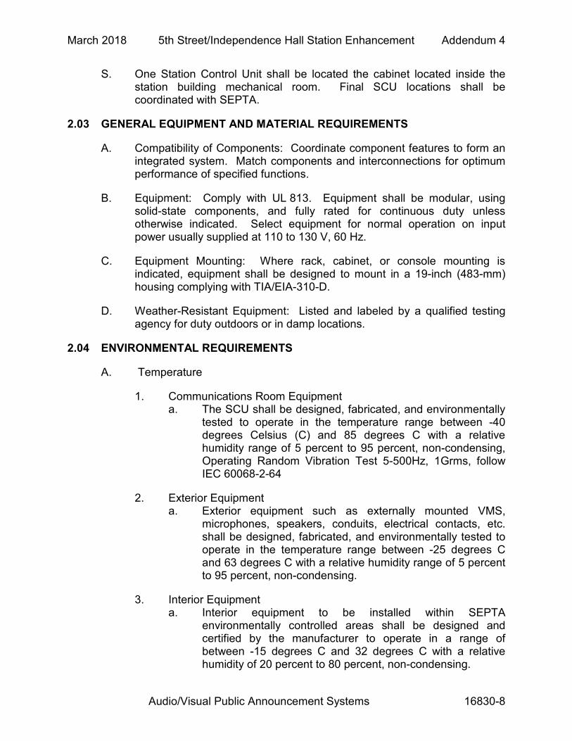
S. One Station Control Unit shall be located the cabinet located inside the station building mechanical room. Final SCU locations shall be coordinated with SEPTA.
2.03 GENERAL EQUIPMENT AND MATERIAL REQUIREMENTS
A. Compatibility of Components: Coordinate component features to form an integrated system. Match components and interconnections for optimum performance of specified functions.
B. Equipment: Comply with UL 813. Equipment shall be modular, using solid-state components, and fully rated for continuous duty unless otherwise indicated. Select equipment for normal operation on input power usually supplied at 110 to 130 V, 60 Hz.
C. Equipment Mounting: Where rack, cabinet, or console mounting is indicated, equipment shall be designed to mount in a 19-inch (483-mm) housing complying with TIA/EIA-310-D.
D. Weather-Resistant Equipment: Listed and labeled by a qualified testing agency for duty outdoors or in damp locations.
2.04 ENVIRONMENTAL REQUIREMENTS
A. Temperature
1. Communications Room Equipment a. The SCU shall be designed, fabricated, and environmentally
tested to operate in the temperature range between -40 degrees Celsius (C) and 85 degrees C with a relative humidity range of 5 percent to 95 percent, non-condensing, Operating Random Vibration Test 5-500Hz, 1Grms, follow IEC 60068-2-64
2. Exterior Equipment a. Exterior equipment such as externally mounted VMS,
microphones, speakers, conduits, electrical contacts, etc. shall be designed, fabricated, and environmentally tested to operate in the temperature range between -25 degrees C and 63 degrees C with a relative humidity range of 5 percent to 95 percent, non-condensing.
3. Interior Equipment a. Interior equipment to be installed within SEPTA
environmentally controlled areas shall be designed and certified by the manufacturer to operate in a range of between -15 degrees C and 32 degrees C with a relative humidity of 20 percent to 80 percent, non-condensing.
March 2018 5th Street/Independence Hall Station Enhancement Addendum 4
Audio/Visual Public Announcement Systems 16830-9
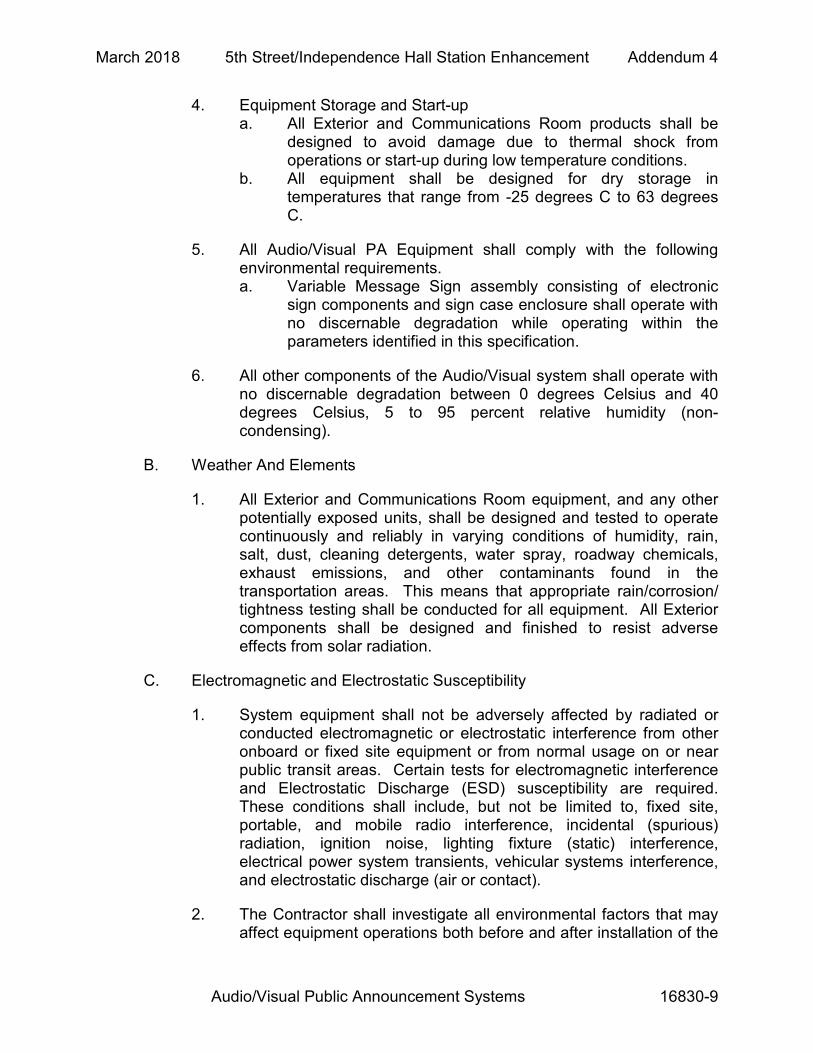
4. Equipment Storage and Start-up a. All Exterior and Communications Room products shall be
designed to avoid damage due to thermal shock from operations or start-up during low temperature conditions.
b. All equipment shall be designed for dry storage in temperatures that range from -25 degrees C to 63 degrees C.
5. All Audio/Visual PA Equipment shall comply with the following environmental requirements. a. Variable Message Sign assembly consisting of electronic
sign components and sign case enclosure shall operate with no discernable degradation while operating within the parameters identified in this specification.
6. All other components of the Audio/Visual system shall operate with no discernable degradation between 0 degrees Celsius and 40 degrees Celsius, 5 to 95 percent relative humidity (non-condensing).
B. Weather And Elements
1. All Exterior and Communications Room equipment, and any other potentially exposed units, shall be designed and tested to operate continuously and reliably in varying conditions of humidity, rain, salt, dust, cleaning detergents, water spray, roadway chemicals, exhaust emissions, and other contaminants found in the transportation areas. This means that appropriate rain/corrosion/ tightness testing shall be conducted for all equipment. All Exterior components shall be designed and finished to resist adverse effects from solar radiation.
C. Electromagnetic and Electrostatic Susceptibility
1. System equipment shall not be adversely affected by radiated or conducted electromagnetic or electrostatic interference from other onboard or fixed site equipment or from normal usage on or near public transit areas. Certain tests for electromagnetic interference and Electrostatic Discharge (ESD) susceptibility are required. These conditions shall include, but not be limited to, fixed site, portable, and mobile radio interference, incidental (spurious) radiation, ignition noise, lighting fixture (static) interference, electrical power system transients, vehicular systems interference, and electrostatic discharge (air or contact).
2. The Contractor shall investigate all environmental factors that may affect equipment operations both before and after installation of the

March 2018 5th Street/Independence Hall Station Enhancement Addendum 4
Audio/Visual Public Announcement Systems 16830-10
equipment, including shock and vibration. Environmental deficiencies uncovered during installation testing, on-line demonstration, or final tests may be cause for additional design adjustments and additional environmental testing by the Contractor. SEPTA shall retain the exclusive right to judge the environmental acceptability of the final acceptance.
D. Electrical Power
1. All components shall be certified via testing to operate with normal outputs when the input voltage varies as much as +/- 10 percent.
E. Shock and Vibration
1. Shock and vibration testing shall be performed. All Exterior and Communications Room equipment, when in their fully assembled configuration, shall not be damaged, nor shall the operational performance be degraded, after subjection to vibration of 1G at 10 Hz to 500 Hz or shocks of 20G for 11 +/- 1 milliseconds in each of three mutually perpendicular planes.
2.05 AVPA SYSTEM TYPICAL EQUIPMENT
A. Station Controller Unit (SCU)
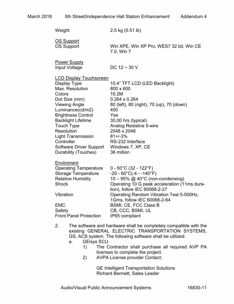
1. The Station Control Units for the Audio/Visual PA System at each station shall be an ADVANTECH, PPC-3100. SCU Specifications:
CPU Intel Atom D2550 1.86 GHz 10W Dual Core
CPU on board Memory SODIMM x 1, DDR3 1066, Max 4GB 2nd Cache Memory 1MB Chipset Intel NM10 Storage mSATA*1 HDD 1 x 2.5” SATA HDD Bay (internal) Processor System I/O Ports 4 x Serial ports: 3 x RS-232, 1 x RS
232/422/485 (Adjustable through BIOS) 4 x USB 2.0 ports, 1 x Line-out, 1 x MIC-in 1 x DB15 VGA, 1 x DB9 GPIO port (8 pin pro-
grammable) Bus Expansion 1 x MINI PCle Network (LAN) 2 x 10/100/1000 Mbps Ethernet Speaker 2 x 1W speakers Watchdog Timer 255 timer levels; setup by software Dimensions (W x H x D) 275 x 220 x 64.3 mm (10.83” x 8.74” x 2.53” )
March 2018 5th Street/Independence Hall Station Enhancement Addendum 4
Audio/Visual Public Announcement Systems 16830-11
Weight 2.5 kg (5.51 lb) OS Support OS Support Win XPE, Win XP Pro, WES7 32 bit, Win CE
7.0, Win 7 Power Supply Input Voltage DC 12 ~ 30 V LCD Display Touchscreen Display Type 10.4” TFT LCD (LED Backlight) Max. Resolution 800 x 600 Colors 16.2M Dot Size (mm) 0.264 x 0.264 Viewing Angle 80 (left), 80 (right), 70 (up), 70 (down) Luminance(cd/m2) 400 Brightness Control Yes Backlight Lifetime 30,00 hrs (typical) Touch Type Analog Resistive 5-wire Resolution 2048 x 2048 Light Transmission 81+/-3% Controller RS-232 Interface Software Driver Support Windows 7, XP, CE Durability (Touches) 36 million Enviroment Operating Temperature 0 - 50°C (32 - 122°F) Storage Temperature -20 - 60°C(-4 - -140°F) Relative Humidity 10 – 95% @ 40°C (non-condensing) Shock Operating 10 G peak acceleration (11ms dura-
tion), follow IEC 60068-2-27 Vibration Operating Random Vibration Test 5-500Hz,
1Gms, follow IEC 60068-2-64 EMC BSMI, CE, FCC Class B Safety CB, CCC, BSMI, UL Front Panel Protection IP65 compliant
2. The software and hardware shall be completely compatible with the existing GENERAL ELECTRIC TRANSPORTATION SYSTEMS, GS, ACS system. The following software shall be utilized: a. GEisys SCU
1) The Contractor shall purchase all required AVP PA licenses to complete the project.
2) AVPA License provider Contact: GE Intelligent Transportation Solutions Richard Bennett, Sales Leader
March 2018 5th Street/Independence Hall Station Enhancement Addendum 4
Audio/Visual Public Announcement Systems 16830-12
2712 S. Dillingham, Grain Valley MO 64029 Phone: (816) 650-4437 Cell Phone: (816) 729-2898 Fax (816) 817-1834
b. Daktronics MetroDVS c. Real VNC software d. VMS Diagnostics software
3. The following summarizes the general operating parameters and functions, within which the combined units shall perform in an operating unit: a. The Station Control Unit will provide a passenger station with
the facilities for selective remote control of platform speaker announcements from either the station Attendant, or SEPTA Control Center operators. The Control Center operators shall have access to any station in the system. The remote control software to perform this capability shall be provided at the SCU.
b. The Station Control Unit shall incorporate priorities on a lock-out basis, which ensures a higher priority user access over a lower priority user. The priorities at the stations are as follows: 1) Highest priority:
a) Station attendant via a microphone b) Station attendant via a message selector c) Control center workstation
2) Lowest priority: a) SCU automated database
c. The system shall be capable of storing up to 500 messages that are nominally 30 seconds in duration (approximately 1,000,000 bytes of data for digitized audio messages).
d. The SCU shall include time synchronization software.
4. Station Control Unit features: a. The Station Control Units shall be enclosed in a
Communications Room cabinet sized appropriately for the amount and size of equipment to be stored and as directed by the SEPTA .
b. All signs shall be connected to the Station Control Units in the cabinet as per the contract drawings. The Station Control Unit and associated electronic equipment shall be designed to operate from -15 degrees C to +60 degrees C.
c. Power filtering and surge protection shall be provided as per the contract drawings.
B. Station Audio Announcement Equipment (Platform Microphone)

March 2018 5th Street/Independence Hall Station Enhancement Addendum 4
Audio/Visual Public Announcement Systems 16830-13
1. Station Platform Microphone shall be installed as per approved drawings.
C. Speakers
1. NEAR Orbit Ceiling Speaker, Model OCS1-MTD as manufactured by Bogen Communications, Inc./ 50 Spring St./Ramsey, New Jersey 07446/ 201-934-8500
2. Product Details a. Construction:
1) One-piece metal alloy cone 2) Unit to be put through hard anodizing process to
create a ceramic surface. 3) Speaker shall consist of one 6 ½” (nominal) low
frequency transducer and one ¾” (nominal) high frequency transducer with a filter network for dividing frequencies between the transducers.
4) The front baffle is to be injection molded, ABS material containing fire inhibitors with a 94VO rating, and the back enclosure shall be plated steel.
5) The ball speaker grille shall be made from heavy-gauge steel.
6) Dimensions shall not exceed 12 3/8” diameter by 12” deep.
7) Weight shall not exceed 10 pounds. 8) Wiring/Power:
b. Each speaker shall have a frequency response from 50 to 15,000 Hz and a power rating of 15 Watts minimum.
c. 16-ohm input d. Provide Snap-On connectors for loop-through wiring to next
speaker. e. Provide input terminal cover with knockouts and safety
eyelets for connection protection. f. All speakers require 18 AWG shielded speaker wire and
should be set to 70.7 V. g. Provide one conduit for speakers. h. Each speaker shall include multi-tap matching transformer
integral to the speaker unit. Speaker power shall be adjusted as required. Wiring terminals for amplifier output shall be fully enclosed, and a vandal-resistant adapter cover shall be provided with a connector for flexible conduit.
3. Mounting: a. Recessed in Drywall Ceiling – Interior b. Recessed in Plasticized T&G Soffit – Exterior
March 2018 5th Street/Independence Hall Station Enhancement Addendum 4
Audio/Visual Public Announcement Systems 16830-14
4. Finish: a. Housing: Bright White b. Speaker Grill: Grey steel grill with fine perforations.
D. LED Variable Message Signs (VMS)
1. Variable message signs shall be used to display visual information from the AVPA System. Signs will be located on the station platforms, mezzanines and concourses. Signs shall be located as shown on the Contract Drawings. Variable Message Signs shall be Daktronics AF-6710-32x256-6-RGB-SF for single sided signs, Daktronics AF-6710-32x256-6-RGB-DF for double sided signs. Sign LED Pitch is 6mm and Sign LEDs are full color RGB > 16 Million Colors. All signs shall utilize RuggedCom RMC-90 pre-installed within the sign housing for connection to the AVPA system, as per approved drawings.
2. All Signs a. Each sign shall be a high-resolution commercially available
embedded Single Board Computer based LED unit consisting of the housing and the interior electronics.
b. All signs and/or sign enclosures shall have sunlight shielding as required. Sunlight shielding shall be used as needed in indoor locations to reduce glare on the Variable Message Signs from lighting fixtures.
c. All signs shall have ambient light sensing which automatically alters the intensity of the display. The ambient light sensing shall be automatically accomplished via electronic means. The use of manual adjustable controls shall not be permitted.
d. Each sign shall be capable of communicating with a host SCU for simultaneous operation with the audio message system. Programmable display effects shall include static, pause, flash, blink, scroll, center, up, down, and jump. The speed of the effects shall be electronically adjustable. Characters to be displayed shall include the entire 256 ASCII character set along with the selected internal characters, and shall support logos, animation and multimedia.
e. The signs shall have the minimum memory to contain 100 messages of 1,000 characters for each message including the display attributes. Multiple fonts shall be available including, but not limited to, ADA compliant aspect ratios, narrow, bold, and wide characteristics.
f. The signs shall conform to FCC Part 15 Class A limits for conducted and radiated emissions of electromagnetic interference.
March 2018 5th Street/Independence Hall Station Enhancement Addendum 4
Audio/Visual Public Announcement Systems 16830-15
g. All connectors shall meet minimum UL 94VO flammability requirements.
h. All signs shall be accessible for servicing and maintenance and have vandal-proof fasteners and/or locks. For service and maintenance, access to the sign electronics shall be provided by opening the front lid and allow for the electronics to be removed. It shall not be necessary to remove the entire sign and housing for maintenance.
i. All signs shall be designed for a minimum life of ten (10) years.
j. Communications with each sign shall be by means of fault tolerant protocol, Ethernet, RS232, RS485 each sign shall have the ability to be uniquely addressed, or addressed by groups. There shall be a minimum of 10,000 different addressable groups.
k. Each sign shall include a quick disconnect harting connector disconnect for removing AC power for maintenance purposes. Line filtering shall be part of the design to minimize faults due to power line transients. Surge protection shall be built in to each sign.
l. All signs shall provide diagnostic information to the station SCU upon power up when requested and if a failure condition is detected. Failure Detection should include LED failure, PSU Failure, Over Temperature and Communication Logging.
m. All sign assemblies (single and double sided) shall provide positive feedback on every command or request received from the SCU.
n. All signs shall have a real time clock that can be set via the sign network. The clock shall be accurate to within 1 second per month. The time and day shall be maintained by each sign, even during power loss.
o. The MTBF of each sign shall be at least 100,000 hours of operation.
p. The LED signs shall have a viewing angle of at least 60 degrees (minimum) off center. The determination of viewing angle shall be when the angled LED illumination intensity is 50 percent of the LED illumination intensity measured at center.
q. The LED panel assemblies shall be modular, interchangeable without re-alignment, and removable.
r. All signs shall operate in the temperature range from –20 degrees C to +55 degrees C, with humidity ranging from 0 to 95 percent, non-condensing. Heating and cooling shall be provided if required to operate in this range. The sign faces shall remain clear and readable in all operating temperature
March 2018 5th Street/Independence Hall Station Enhancement Addendum 4
Audio/Visual Public Announcement Systems 16830-16
ranges and humidity. Any and all temperature control subsystems shall be thermostatically controlled. All sign enclosures shall be as specified in Article 2.04-C.
s. Sign types at each installation are specified on the approved Drawings. The sign types shown on the approved Drawings include the following configurations: 1) Single line, single sided, Full Color RGB. Mount:
Standard Signfix Extrusion Mounting Bracket a) Single Sided Sign to be mounted local to ticket
vending machine lineup at Eastbound and Westbound Platforms.
b) Provide galvanized, and painted metal angles to hold sign in place and allow for installation and repair access.
c) This installation to be custom designed through building contractor and sign manufacturer and approved by SEPTA.
d) This installation may require lag bolts, an additional header, and blocking.
e) Overall Dimensions 67.6” (nominal) wide x 13.75” (nominal) high x 14.4” (nominal) deep.
2) Double line, single sided, Full Color RGB. Mount: Standard Signfix Extrusion Mounting Bracket a) Double Sided Signs to be mounted under
canopy to soffit. b) This installation will require blocking and or
bracing between the roof trusses. c) Door shall have hold-open capability through
gas struts. d) Provide four external lift hinges per door
(chrome plated finish) e) Provide four 7.5mm triangle key locks per door
(chrome plated finish) f) Provide Signfix Extrusion Profile g) Provide Harting Connector Power and Signal
Entry h) Case Color: Powder Coated Gloss Aluminum i) Overall Dimensions 67.6” (nominal) wide x
13.75” (nominal) high x 14.4” (nominal) deep.
t. All signs shall have 18 characters per line minimum represented by the ADA compliant font with using 96 millimeters for character height minimums. All sign text letters shall be upper case. The signs shall be sun light readable and have a minimum 5,000 candela per meter squared brightness, designed for outdoor operation. The

March 2018 5th Street/Independence Hall Station Enhancement Addendum 4
Audio/Visual Public Announcement Systems 16830-17
LED pixels shall be totally viewable while in the enclosures. The same style, size, model, and type of sign for all single and double sided signs shall be used at all locations.
u. All signs shall provide their own temperature control. All signs shall be convection cooled. The sign electronics shall sense any temperature faults (over-heating and under-heating) and report to the Station Control Unit. The sign electronics shall be fault protected so that temperature conditions do not damage any sign components.
v. All sign input power requirements shall be 120VAC, 60 Hz, single phase 3 amps for single sided signs and 6 amps for double sided signs. Signs shall be protected by internal circuit breaker and surge suppressor from the nearest panel board feeders.
w. The Sign shall utilize power supplies that are internal to the Sign enclosure.
3. Sign Housing/Enclosure a. Each exterior housing shall be modular, vandal resistant,
water tight and corrosion resistant. All sign components, including but not limited to, LED grids, electronics, power supplies, sensors, etc., shall be fastened and enclosed in NEMA 4X certified housings as an integrated unit.
b. All signs shall be designed and constructed so as to present a clean neat appearance. Poor workmanship shall be cause for rejection of the sign.
c. Any and all cable attachments to the sign and/or sign housing shall have the cables securely clamped without the use of adhesives.
d. The sign housing, mounting brackets, and cabling shall be designed to withstand winds of up to 193 kilometers per hour (120 miles per hour) without permanent deformation or other damages. Performance of the sign shall not be impaired by wind or weather. The sign mounting shall support a minimum of 227 kilograms (500 lbs.), including signs mounted on poles, canopies, ceilings and walls.
e. The sign electronics shall have over/under voltage and surge protection for both data and power supply lines. The electronics shall be isolated from the enclosure and hardware. All sign enclosures shall have internal circuit protection and breaker systems with a reset device. All electronics enclosed in the sign shall be connected to the enclosed sign power block for circuit protection.
f. All electronic components, except printed circuit boards, shall be commercially available, easily accessible, replaceable and individually removable using conventional electronics repair methods.
March 2018 5th Street/Independence Hall Station Enhancement Addendum 4
Audio/Visual Public Announcement Systems 16830-18
g. All external screws, nuts, and locking washers shall be corrosion resistant and vandal resistant. No self-tapping screws shall be used on the exterior of the signs. All external parts and mounting brackets shall be made of corrosion resistant materials and shall be moisture resistant. Dissimilar metals shall be separated by an inert dielectric material.
h. The sign housings shall have a minimum number of seams. All exterior seams and joints shall be sealed to form a rain-tight enclosure.
i. The sign housing exteriors shall be aluminum, powder-coated to match the canopy columns. The Contractor shall provide a sample housing with the sign display face for SEPTA approval before fabrication and installation.
j. The sign display faces shall be polycarbonate Lexan MR5, gray 713, with a 6 millimeter minimum thickness, or approved equivalent. The faces shall be easily cleanable, scratch proof, and vandal resistant.
k. All areas of the sign faces not used in the sign display shall be made opaque, matte black.
l. All sign enclosures shall have sun shielding covers and faces as required.
4. Sign Software a. Sign communications software shall be “Daktronics Metro
DVS” or SEPTA approved equivalent VMS control and diagnostics software. All sign software shall be approved by SEPTA before installation is allowed.
b. All sign software, configuration data and memory data shall be updated electronically. Component exchanging shall not be permitted.
c. The sign shall provide the software version number on demand.
d. All system and component software, including, but not limited to, LED signs, PA Systems, Station Control Units, AVPA workstations and Servers, shall be a tested, released version only. No software shall be permitted in any part of the system that is not a controlled, released version. All like equipment shall have the same versions of software. All software components shall be submitted and turned over to SEPTA at the completion of the Project.
e. Any updated versions of the system and component software shall be backwards compatible with the other system and component software.
f. Upon power up or reset, the sign shall display all version numbers, date, time, communications configuration data, and status data.
March 2018 5th Street/Independence Hall Station Enhancement Addendum 4
Audio/Visual Public Announcement Systems 16830-19
g. Diagnostics shall include test patterns, memory configuration, alarms, faults, relay logic and LED defect detection.
h. Sign message organization shall show train arrival frequency information, current time, and service messages.
i. Sign Must incorporate a Local Maintenance Port for Configuration and Diagnostics
j. Sign Must Support remote Diagnostics, Configuration through manufacturer’s maintenance application.
2.06 CONDUCTORS AND CABLES
A. Retain this article unless cabling is specified in Division 16 Section "Communications Horizontal Cabling."
B. Power and signal cables shall be installed in separate raceways.
C. The equipment shall be wired such that 20 Amp (maximum) branch circuits are required for power.
D. Provide system wiring materials as follows:
1. Signal control and data cables shall be Category 6 Shielded or Multimode fiber and conform to EIA/TIA 568A. cable.
2. Speaker Wire: 1 TWPR, 16 AWG, shielded; plenum insulation, aluminum polyester shield, chrome sunlight resistant jacket, temperature rating: 105 degrees Celsius, and voltage rating: 300 volts.
3. SCU Link: Category 6; Polypropylene insulation, 4 twisted pairs, under aluminum polyester shield, pairs cabled on common axis to reduce diameter, jacketed, NEC CM temperature rating: 60 degrees Celsius, and voltage rating: 300 volts.
4. Platform Microphone: Category 6 Shielded AC wiring to all devices shall be grounded via the identified grounding conductor and shall not utilize the conduits or other raceway. The Contractor shall produce wiring diagrams showing the circuit breaker numbers, wire gauges, wire paths and connections.
5. All control and data cables shall have tinned copper conductors.
6. Ethernet connections shall be multimode fiber between SCU and signs.
March 2018 5th Street/Independence Hall Station Enhancement Addendum 4
Audio/Visual Public Announcement Systems 16830-20
E. Variations of the above listed cable may be used upon approval by SEPTA.
F. Furnish all equipment, hardware, accessories, terminal blocks, cabinets, conduits, raceway, cable trays, cables, and wire required for mechanical and electrical installation of the Audio/Visual PA Systems as herein defined.
2.07 RACEWAYS
A. Conduit and Boxes: Comply with Division 16 Section "Raceways.” Flexible metal conduit shall not be used.
PART 3 - EXECUTION
3.01 WIRING METHODS
A. Wiring Method: Install cables in raceways and cable trays except within consoles, cabinets, desks, and counters, and except in accessible ceiling spaces and in gypsum board partitions where unenclosed wiring method may be used. Conceal raceway and cables except in unfinished spaces.
1. Install plenum cable in environmental air spaces, including plenum ceilings.
2. Comply with requirements for raceways and boxes specified in Division 16 Section "Raceways.”
B. Wiring Method: Conceal conductors and cables in accessible ceilings, walls, and floors where possible.
C. Wiring within Enclosures: Bundle, lace, and train cables to points with no excess and without exceeding manufacturer's limitations on bending radii. Provide and use lacing bars and distribution spools.
3.02 INSTALLATION OF RACEWAYS
A. Comply with requirements in Division 16 Section "Raceways” for installation of conduits and wireways.
B. Install manufactured conduit sweeps and long-radius elbows whenever possible.
3.03 INSTALLATION OF CABLES
A. Comply with NECA 1.
B. General Cable Installation Requirements:
March 2018 5th Street/Independence Hall Station Enhancement Addendum 4
Audio/Visual Public Announcement Systems 16830-21
1. Terminate conductors; no cable shall contain unterminated elements. Make terminations only at outlets and s.
2. Splices, Taps, and Terminations: Arrange on numbered strips in junction, pull, and outlet boxes; cabinets; and equipment enclosures. Cables may not be spliced.
3. Secure and support cables at intervals not exceeding 30 inches and not more than 6 inches from cabinets, boxes, fittings, outlets, racks, frames, and s.
4. Bundle, lace, and train conductors to points without exceeding manufacturer's limitations on bending radii. Install lacing bars and distribution spools.
5. Do not install bruised, kinked, scored, deformed, or abraded cable. Do not splice cable between termination, tap, or junction points. Remove and discard cable if damaged during installation and replace it with new cable.
6. Cold-Weather Installation: Bring cable to room temperature before dereeling. Heat lamps shall not be used.
C. Open-Cable Installation:
1. Install cabling with horizontal and vertical cable guides in telecommunications spaces with terminating hardware and interconnection equipment.
2. Suspend speaker cable not in a wireway or pathway a minimum of 8 inches above ceiling by cable supports not more than 60 inches apart.
3. Cable shall not be run through structural members or be in contact with pipes, ducts, or other potentially damaging items.
D. Separation of Wires: Separate speaker-microphone, line-level, speaker-level, and power wiring runs. Install in separate raceways or, where exposed or in same enclosure, separate conductors at least 12 inches apart for speaker microphones and adjacent parallel power and telephone wiring. Separate other intercommunication equipment conductors as recommended by equipment manufacturer.
3.04 INSTALLATION
A. Match input and output impedances and signal levels at signal interfaces. Provide matching networks where required.

March 2018 5th Street/Independence Hall Station Enhancement Addendum 4
Audio/Visual Public Announcement Systems 16830-22
B. Identification of Conductors and Cables: Color-code conductors and apply wire and cable marking tape to designate wires and cables so they identify media in coordination with system wiring diagrams.
C. Equipment Cabinets and Racks:
1. Group items of same function together, either vertically or side by side, and arrange controls symmetrically. Mount monitor panel above the amplifiers.
2. Arrange all inputs, outputs, interconnections, and test points so they are accessible at rear of rack for maintenance and testing, with each item removable from rack without disturbing other items or connections.
3. Blank Panels: Cover empty space in equipment racks so entire front of rack is occupied by panels.
D. Volume Limiter/Compressor: Equip each zone with a volume limiter/compressor. Install in central equipment cabinet. Arrange to provide a constant input to power amplifiers.
E. Wall-Mounted Outlets: Flush mounted.
F. Floor-Mounted Outlets: Conceal in floor and install cable nozzles through outlet covers. Secure outlet covers in place. Trim with carpet in carpeted areas.
G. Conductor Sizing: Unless otherwise indicated, size speaker circuit conductors from racks to loudspeaker outlets not smaller than No. 18 AWG and conductors from microphone receptacles to amplifiers not smaller than No. 22 AWG.
H. Weatherproof Equipment: For units that are mounted outdoors, in damp locations, or where exposed to weather, install consistent with requirements of weatherproof rating.
I. Speaker-Line Matching Transformer Connections: Make initial connections using tap settings indicated on Drawings.
J. Connect wiring according to Division 16 Section "Wires and Cables."
3.05 GROUNDING
A. Ground cable shields and equipment to eliminate shock hazard and to minimize ground loops, common-mode returns, noise pickup, cross talk, and other impairments.

March 2018 5th Street/Independence Hall Station Enhancement Addendum 4
Audio/Visual Public Announcement Systems 16830-23
B. Signal Ground : Locate at main equipment cabinet. Isolate from power system and equipment grounding.
C. Install grounding electrodes as specified in Division 16 Section "Grounding and Bonding."
3.06 FIELD QUALITY CONTROL
A. Testing Agency: Engage a qualified testing agency to perform tests and inspections.
B. Manufacturer's Field Service: Engage a factory-authorized service representative to inspect, test, and adjust components, assemblies, and equipment installations, including connections.
C. Perform tests and inspections.
1. Manufacturer's Field Service: Engage a factory-authorized service representative to inspect components, assemblies, and equipment installations, including connections, and to assist in testing.
D. Tests and Inspections:
1. Schedule tests with at least seven days' advance notice of test performance.
2. After installing public address and mass notification systems and after electrical circuitry has been energized, test for compliance with requirements.
3. Operational Test: Perform tests that include originating program and page messages at microphone outlets, preamplifier program inputs, and other inputs. Verify proper routing and volume levels and that system is free of noise and distortion.
4. Signal-to-Noise Ratio Test: Measure signal-to-noise ratio of complete system at normal gain settings as follows: a. Disconnect microphone at connector or jack closest to it and
replace it in the circuit with a signal generator using a 1000-Hz signal. Replace all other microphones at corresponding connectors with dummy loads, each equal in impedance to microphone it replaces. Measure signal-to-noise ratio.
b. Repeat test for each separately controlled zone of loudspeakers.
c. Minimum acceptance ratio is 50 dB.
5. Distortion Test: Measure distortion at normal gain settings and rated power. Feed signals at frequencies of 50, 200, 400, 1000,

March 2018 5th Street/Independence Hall Station Enhancement Addendum 4
Audio/Visual Public Announcement Systems 16830-24
3000, 8000, and 12,000 Hz into each preamplifier channel. For each frequency, measure distortion in the paging and all-call amplifier outputs. Maximum acceptable distortion at any frequency is 3 percent total harmonics.
6. Acoustic Coverage Test: Feed pink noise into system using octaves centered at 500 and 4000 Hz. Use sound-level meter with octave-band filters to measure level at five locations in each zone. For spaces with seated audiences, maximum permissible variation in level is plus or minus 2 dB. In addition, the levels between locations in same zone and between locations in adjacent zones must not vary more than plus or minus 3 dB.
7. Power Output Test: Measure electrical power output of each power amplifier at normal gain settings of 50, 1000, and 12,000 Hz. Maximum variation in power output at these frequencies must not exceed plus or minus 1 dB.
8. Signal Ground Test: Measure and report ground resistance at pubic address equipment signal ground. Comply with testing requirements specified in Division 16 Section "Grounding and Bonding."
E. Inspection: Verify that units and controls are properly labeled and interconnecting wires and s are identified. Prepare a list of final tap settings of paging speaker-line matching transformers.
F. Public address and mass notification systems will be considered defective if they do not pass tests and inspections.
G. Prepare test and inspection reports.
1. Include a record of final speaker-line matching transformer-tap settings, and signal ground-resistance measurement certified by Installer.
3.07 STARTUP SERVICE
A. Engage a factory-authorized service representative to perform startup service.
1. Verify that electrical wiring installation complies with manufacturer's submittal and installation requirements.
2. Complete installation and startup checks according to manufacturer's written instructions.

March 2018 5th Street/Independence Hall Station Enhancement Addendum 4
Audio/Visual Public Announcement Systems 16830-25
3.08 ADJUSTING
A. On-Site Assistance: Engage a factory-authorized service representative to provide on-site assistance in adjusting sound levels, resetting transformer taps, and adjusting controls to meet occupancy conditions.
B. Occupancy Adjustments: When requested within 12 months of date of Substantial Completion, provide on-site assistance in adjusting system to suit actual occupied conditions. Provide up to 2 visits to Project during other-than-normal occupancy hours for this purpose.
3.09 DEMONSTRATION
A. Engage a factory-authorized service representative to train Owner's maintenance personnel to adjust, operate, and maintain the public address and mass notification systems and equipment. Training shall occur over (4) separate sessions. Provide for (2) sessions during normal operating hours (day shift) and (2) sessions during off hours (night shift).
END OF SECTION 16830

March 2018 5th Street/Independence Hall Station Enhancement Addendum 4
Audio/Visual Public Announcement Systems 16830-26
NO TEXT THIS PAGE