Embed Size (px)
Citation preview
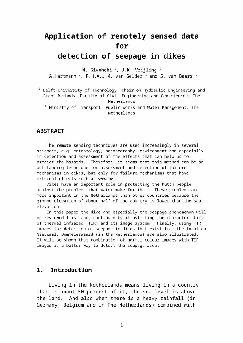
Application of remotely sensed data for detection of seepage in dikes
M. Givehchi 1, J.K. Vrijling 1
A.Hartmann 2, P.H.A.J.M. van Gelder 1 and S. van Baars 1
1 Delft University of Technology, Chair on Hydraulic Engineering and Prob. Methods, Faculty of Civil Engineering and Geosciencee, The Netherlands
2 Ministry of Transport, Public Works and Water Management, The Netherlands
ABSTRACT
The remote sensing techniques are used increasingly in several sciences, e.g. meteorology, oceanography, environment and especially in detection and assessment of the effects that can help us to predict the hazards. Therefore, it seems that this method can be an outstanding technique for assessment and detection of failure mechanisms in dikes, but only for failure mechanisms that have external effects such as seepage. Dikes have an important role in protecting the Dutch people against the problems that water make for them. These problems are more important in the Netherlands than other countries because the ground elevation of about half of the country is lower than the sea elevation. In this paper the dike and especially the seepage phenomenon will be reviewed first and, continued by illustrating the characteristics of thermal infrared (TIR) and its image system. Finally, using TIR images for detection of seepage in dikes that exist from the location Nieuwaal, Bommelerwaard (in the Netherlands) are also illustrated. It will be shown that combination of normal colour images with TIR images is a better way to detect the seepage area.
1. Introduction
Living in the Netherlands means living in a country that in about 50 percent of it, the sea level is above the land. And also when there is a heavy rainfall (in Germany, Belgium and in The Netherlands) combined with snow melting in the mountains of Austria (Alps) or Belgium (Ardennes) the rivers show a large discharge and very high water levels. So not only the sea is a threat to the Dutch people, also river discharges can cause problems. Thus, the threats for the Netherlands' water system can be: sea, river and rain [Pluym D. Keij W.D., 2000]. Obviously the Dutch people want to protect themselves from these hazards, so dikes and dunes have been built through the centuries. Without dunes and dikes about half of the country would be submerged. In this way, the dikes play an important role in the safety of the Dutch people. Therefore it is extremely important that changes in the condition of dikes are measured and a suitable reaction is chosen. Hence a more efficient method than visual inspection or photographs was sought and it was found that Remote Sensing could be effective. And it is anticipated that by using remote sensing all failure mechanism in dikes that have external effects can be evaluated. The changes in the conditions of dikes (such as moisture) that can cause failure in dikes are also measured. The outline of this paper is as follows. First, the dikes, the failure mechanisms of dikes and the proxies of the failure mechanisms that are important for monitoring will
1

be described (section 2). Then in section 3, remote sensing and essentially thermal infrared (TIR) will be explained. Finally, using TIR images for detection of seepage in dikes that exist from the location Nieuwaal, Bommelerwaard will be also illustrated (section 4).
2. Dike
A dike is a hydraulic structure for which ground (sand and clay) is the main material. It is used for protection against floods or in another word it protects the area against attacks the water and flood (Fig. 1). Several kinds of soils are used in making dikes and different materials are used for dike's protection. Choosing them depends on different parameters such as the type of ground below the dike, the materials available, the pressure the dike must withstand, the traditions, customs of the area and etc. In the Netherlands mostly use clay and sand for making a dike and it is protected with an impermeable layer. This impermeable layer is usually clay but some times supplemented by asphalt. This layer must resist against scouring. In addition a grass cover with a healthy layer of turf is also used. It is known the cheaper and best protection for dikes especially when the outer slope of dike is far away from waves and tides. But outer slopes of dikes, which are subject to heavier attack of waves, are usually protected with a revetment of stone or concrete blocks. In order to monitor the dikes with remote sensing, it is important to know the potentials failure mechanisms. For a typical dike cross-section various potentials failure mechanisms can be distinguished, which are:
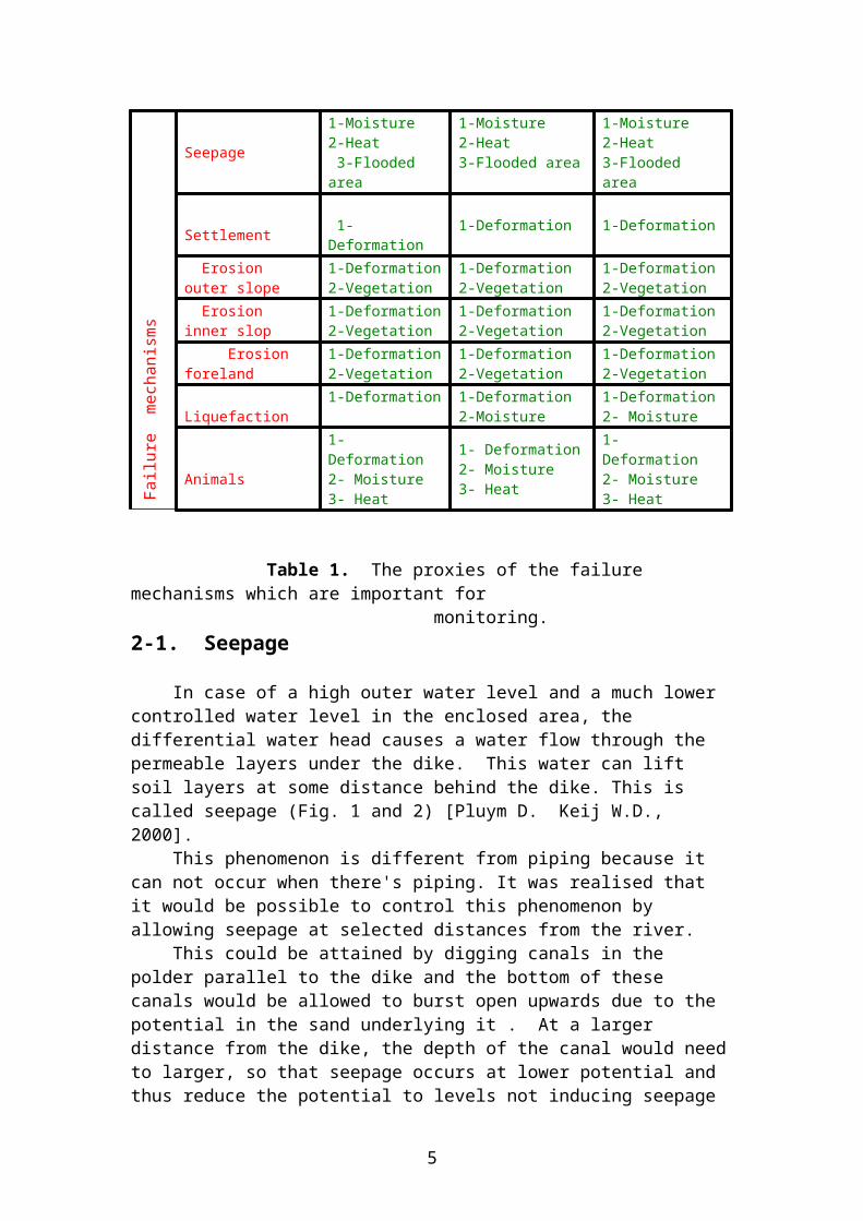
1 - Overflowing 2 - Wave overtopping 3 - Sliding inner slope 4 - Sliding outer slope 5 - Piping 6 - Seepage 7 - Settlement 8 - Erosion inner slope 9 - Erosion outer slope10 - Erosion foreland11 - Liquefaction12 - Animals The above mentioned failure mechanisms are those, which have external effects that can be evaluated by using the remote sensing. The changes in the conditions of dikes (such as moisture) that can cause failure are also noted. For the application of remote sensing for dike systems distinction is made between safety testing (normal loading), flood and after flood (maintenance and management monitoring). Therefore, based on characteristics of various failure mechanisms that can be distinguished for typical dike cross section, table 1 is made. This table shows the proxies that introduce the failure mechanisms and remote sensing is able to recognise them. In this paper only the seepage will be studied.
2

Loading conditions
Proxies
Normal
(Safety testing)
Flood After flood
( Maintenance & Management )
Fai
lure
mec
hani
sms
Overflowing
1- Crest height 1- Crest height2- Elevation of water
1- Deformations2- Flooded area3-Vegetation
Wave overtopping 1- Crest height 1- Crest height
2- Elevation of water 3- Deformations
1- Deformations2- Flooded area3-Vegetation
Sliding inner slope
1-Deformation2-Moisture3-Heat4-Vegetation
1-Deformation2-Moisture3-Heat4-Vegetation
1-Deformation2-Moisture3-Heat4-Vegetation
Sliding outer slope
1-Deformation2-Moisture3-Heat4-Vegetation
1-Deformation2-Moisture3-Heat4-Vegetation
1-Deformation2-Moisture3-Heat4-Vegetation
Piping1-Deformation2-Moisture3-Heat4-Flooded area
1-Deformation2-Moisture3-Heat4-Flooded area
1-Deformation2-Moisture3-Heat4-Flooded area
Seepage 1-Moisture2-Heat 3-Flooded area
1-Moisture2-Heat3-Flooded area
1-Moisture2-Heat3-Flooded area
Settlement 1-Deformation 1-Deformation 1-Deformation
Erosion outer slope 1-Deformation2-Vegetation
1-Deformation2-Vegetation
1-Deformation2-Vegetation
Erosion inner slop 1-Deformation2-Vegetation
1-Deformation2-Vegetation
1-Deformation2-Vegetation
Erosion foreland 1-Deformation 2-Vegetation
1-Deformation 2-Vegetation
1-Deformation 2-Vegetation
Liquefaction 1-Deformation 1-Deformation 2-Moisture
1-Deformation 2- Moisture
Animals1- Deformation2- Moisture3- Heat
1- Deformation2- Moisture3- Heat
1- Deformation2- Moisture3- Heat
Table 1. The proxies of the failure mechanisms which are important for monitoring.2-1. Seepage
In case of a high outer water level and a much lower controlled water level in the enclosed area, the differential water head causes a water flow through the permeable
3

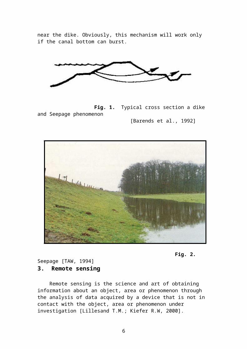
layers under the dike. This water can lift soil layers at some distance behind the dike. This is called seepage (Fig. 1 and 2) [Pluym D. Keij W.D., 2000]. This phenomenon is different from piping because it can not occur when there's piping. It was realised that it would be possible to control this phenomenon by allowing seepage at selected distances from the river. This could be attained by digging canals in the polder parallel to the dike and the bottom of these canals would be allowed to burst open upwards due to the potential in the sand underlying it . At a larger distance from the dike, the depth of the canal would need to larger, so that seepage occurs at lower potential and thus reduce the potential to levels not inducing seepage near the dike. Obviously, this mechanism will work only if the canal bottom can burst.
Fig. 1. Typical cross section a dike and Seepage phenomenon [Barends et al., 1992]
Fig. 2. Seepage [TAW, 1994]3. Remote sensing
Remote sensing is the science and art of obtaining information about an object, area or phenomenon through the analysis of data acquired by a device that is not in contact
4
with the object, area or phenomenon under investigation [Lillesand T.M.; Kiefer R.W, 2000]. Electromagnetic spectrum is employed in the remote sensing for detection and measuring target characteristics. Electromagnetic spectrum is the continuum of energy that ranges from the very short wavelengths of the Gama-ray region (measured in fractions of nanometers) to the long wavelengths of the radio region (measured in meters), travels at the speed of light and propagates through vacuum such as outer space. 3.1 Thermal Infrared (TIR)
The IR (Infrared) region is that portion of the electromagnetic spectrum ranging in wavelength from o.7 μm to 1 mm. The IR portion can be classified in two methods:
- Based on nearness to the visible Light, which are classified:
- Near Infrared 0.7- 1.3 μm- Middle Infrared 1.3 - 3 μm- Far Infrared 3 μm until 1 mm
- According to their nature :
- Reflected Infrared .7 - 3 μm- Thermal Infrared 3 - 14 μm
In this paper, the second definition is used. The main source of the reflected IR is sun and 40 % of the sun's energy that earth has been receiving is in this portion, but the main source that produce the Thermal IR energy is the heat of earth which is due to the sun shine to the earth. All objects in the world that have a temperature more than 0 K (0 K = -273 C) have radiant energy. For example, earth radiates energy both day and night, with the maximum energy radiating at 9.7 μm wavelength. This radiant energy peak occurs in the thermal portion of the IR region. The reflected IR region includes the photographic IR band (0.7 to 0.9 μm), which may be detected directly by IR sensitive film. On IR colour photographs the red signature records IR energy that is strongly reflected by vegetation and is not related to thermal radiation. Within the IR portion of the spectrum, it should be noted that only Thermal IR energy is directly related to the sensation of heat and Reflected IR energy is not. Therefore photographic film does not detect TIR radiation. Special detectors and optical-mechanical scanners detect and record images in thermal IR spectral region. In the TIR images, the brightest tones represent the warmest radiant temperature and the darkest tones represent the coldest tone. The atmosphere does not transmit all wavelengths of thermal IR radiation uniformly. Carbon dioxide, ozone and water vapour absorb energy in certain wave length regions (call absorption bands). The atmosphere transmits wavelengths of 3 to 5 μm and 8 to 14 μm (Fig. 3). The narrow absorption band of 9 to 10 μm (shown as a dashed curve in Fig. 3) is caused by the ozone layer at the top of the earth's atmosphere. To avoid the effects of this absorption band, satellite TIR systems record
5
wavelengths from 10.5 to 12.5 μm. Systems on aircraft, which fly beneath the ozone layer, are not affected and may record the full window from 8 to14 μm.
Fig. 3. Electromagnetic spectrum showing spectral bands used in the thermal IR region. Gases that cause atmospheric absorption are indicated [Sabins,1997].
4. Case Study
During the fast increase of water elevation in the river Waal at the location Nieuwaal, Bommelerwaard (Fig. 4), on January 1995, TIR images and normal colour images which were prepared by Directie Noordzee (Ministry of public work- department North Sea) has been taken to the Meetkundige Dienst (Survey department). This office does the image processing. Before the actual processing of the images can be started, the data is saved digitally in a workstation at the Meetkundige Dienst. And after that further changes with image program "ERDAS- Imagine" are possible. The next step is the geometrically correction of the data because the planes have irregular movements during the flight. This implies that the data is transformed to a co-ordinate system. The resulted data will be matched with an other geographic information system. Correcting aeroplane data geometrically is a time consuming business. After importing and geometrically correcting the data, the images are being analysed. Notice, the colour videotape that was taken from the crisis area, can be watched directly after the flight with the help of an S-VHS video recorder, because the video data is saved on S-VHS videotapes. This is fastest way to get at actual and
6
Fig. 4. The map of the Nieuwaal, Bommelerwaard (Netherlands)
recognisable overview of the critical areas but that doesn't have clear information about seepage (Fig. 7). The TIR videotape can also be watched directly with an S-VHS video recorder, though the interpretation is somewhat more difficult. The images that you can see contains temperature difference depicted in grey colour which make the landscape
less easy to recognises (Fig. 5). The TIR images are adapted in such a way to show potential places of seepage (Fig. 5 and 6). Because when the temperature of the water is higher that that of land, the water will be depicted white while the land is clearly identifiable in darker grey tints. It has to be said that this method is only then useful, when a temperature difference between land and water exists. In figure 6, the brightest areas in the down and middle of the picture shows the water in the inner slope of dike (seepage). This water is warmer than soil (body of dike) and the water in the outer slope of the dike (water in the river, right side of the picture), so the seepage areas have the highest brightness in the picture. The body of dike is colder than the water in the inner slope and outer slope of dike, therefore it is shown with dark tone in the picture in compression with the other parts. The water in the river (in the outer slope of dike) is warmer than soil and colder than seepage (right side of picture); thus it is shown with lower brightness.
7
Nieuwaal

With the help of digital image processing, these video and geometrically corrected TIR-strips of the same surroundings, were combined by Fraikin et al. (1995)(figure 8). This combination is based on the change of intensity of the video image to the intensity of the TIR record. In this way the colour and clarity of the original video image is stored but the contrast is determined by the TIR image. The result shows an image in which the qualities of video (overview and identification) are combined with the qualities of TIR images (reproduction of temperature differences, seepage).
5. Conclusion
This paper argues that thermal infrared method can be a useful method for detecting seepage. It is anticipated that using other remote sensing methods can assess other failure mechanisms in dikes as well.The output of the remote sensing is a continuous view of the measuring. This is one of its advantages, especially for linear projects (e.g. dikes) and large areas for which the amount of data is very much. Fortunately, by having high speed, capacity computers, detection of critical points during crisis situations is done faster and easier. The integration of airborne normal images and TIR images can be a useful technique for interpretation an assessment seepage although the TIR images can be used separately. The TIR images for detection seepage can be used not only for normal loading (safety testing) but also during flood and after flood (maintenance and management monitoring).
8
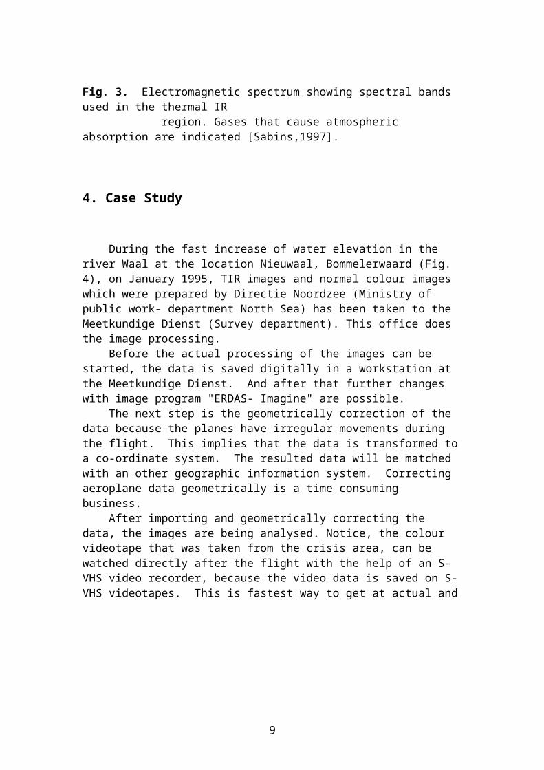
Fig. 5. Geometrical corrected TIR image of the dike at Nieuwaal, Bommelerwaard ,31 January 1995 [Fraikin et al., 1995]
9
7.45 m
70 m
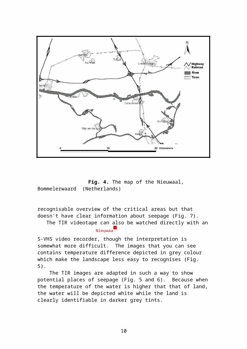
Fig. 6. Detail of the TIR image of Fig. 5 ,which shows the seepage clearly ( light
colour )[Fraikin et al., 1995]
Fig. 7. Digital geometric corrected video-mosaic of the dike at Nieuwaal, Bommelerwaard , 31 January 1995 [Fraikin et al., 1995]
10
7.45 m

Fig. 8. Combination of TIR image (Fig. 6) and video image (Fig. 7) [Fraikin et al., 1995]References
1 - Pluym D., Keij W.D. (2000). Organisation of SAR-based deformation measurements on river dikes, Delft University and Technology.
2 - Barends F.B.J., Haan E.J., Venmans A.A.M. (1992). Report state of the art Dutch dike technology.
3 - TAW (1991). Guide for design of river dikes .Volume 1 - upper river area. Technical advisory committee on water defences. ISBN 9037600115
4 - TAW (1990). Probabilistic design of flood defences. Technical advisory Committee on water defences. ISBN 9037600093
5 - Hirschfeld R.C., Poulos S.J. (1973). Embankment dam engineering ISBN 0-471-40050-5. Printed by John Wiley & Sons.
6 - Walker W. et al. (1993). Investigating basic principles of river dike improvement. ISBN 0-8330-1366-1 7 - TAW (1994). Water against thedike-1993. Technical advisory committee on Water defences.
8 - TAW (1988). Water against the dike. Technical advisory committee on water defences. ISBN 9037600026
9 - Fraikin S., Hartmann R., Reijneveld A. (1995). Remote Sensing Rijkswaterstaat Wateroverlast. Meetkundige Dienst- The Netherlands.
10- Lillesand T.M., Kiefer R.W (2000). Remote sensing and image interpretation. ISBN 0-471-25515-7
11- Sabins F.F. (1997). Remote Sensing, principal and interpretation. ISBN 0-7167-2442-1.
12- Singhroy V. (1995). SAR integrated techniques for geohazard assissment, Advances In Space Research , 15(11): 67-78.
13- Dhakal A. S., Amada T., Aniya M., Sharma R.R. (2002). Detection of areas associated with flood and erosion caused by a heavy rainfall using multitemporal Landsat TM data, Photogrammetric Engineering & Remote Sensing, 68 (3): 233- 239.
11
7.45 m