Embed Size (px)
Citation preview
ORNL/M—2377
DE93 003111
HEIR SPENT FUEL MANAGEMENT ALTERNATIVES
John M. Begovich Victoria M. Green Larry B. Shappert
Chemical Technology Division
A. L. (Pete) Lotts
Consultant
Prepared by the OAK RIDGE NATIONAL LABORATORY
Oak Ridge, Tennessee 37831 managed by
MARTIN MARIETTA ENERGY SYSTEMS, INC. for the
U.S. DEPARTMENT OF ENERGY under Contract No. DE-AC06-840R21400
dtSTFHBUTiON OF THIS DOCUMENT IS UNLIMITED
n October 15, 1992
CONTENTS
PAGE
ACRONYMS iii
LIST OF TABLES v
LIST OF FIGURES vi !i
ABSTRACT vii !
1. INTRODUCTION 1 1.1 TASK CONSTRAINTS 2
1.1.1 HFIR Space and Time Constraints 2 ; 1.1.2 Other Research Reactor Needs 2 ;
1.2 SHORT-TERM ALTERNATIVES IDENTIFIED FOR STUDY 3 j;
2. REGULATORY AND OTHER REQUIREMENTS 5 2.1 SAFEGUARDS AND SECURITY REQUIREMENTS 5 2.2 NEPA REQUIREMENTS 8 2.3 RCRA REQUIREMENTS 10 2.4 TRANSPORTATION REQUIREMENTS 12 2.5 SAFETY DOCUMENTATION REQUIREMENTS 13 2.6 NUCLEAR CRITICALITY SAFETY REQUIREMENTS 15
3. DRY CASK STORAGE ALTERNATIVE 16 3.1 DESCRIPTION OF DRY CASK STORAGE 16 3.2 SITING OPTIONS INVESTIGATION 20
3.2.1 Adjacent to Building 7900 20 3.2.2 Solid Waste Storage Area 20
3.3 REGULATORY AND OTHER REQUIREMENTS 21 3.3.1 Safeguards and Security Requirements 21 3.3.2 NEPA Requirements 22 3.3.3 RCRA Requirements 22 3.3.4 Transportation Requirements 22 3.3.5 Safety Documentation Requirements 23 3.3.6 Nuclear Criticality Safety Requirements 23
3.4 FEASIBILITY OF DRY CASK STORAGE AS SHORT-TERM ALTERNATIVE 24
3.5 COST AND SCHEDULE ESTIMATES 24
'4. ORNL POOL STORAGE ALTERNATIVE 29 4.1 DESCRIPTION OF ORNL REACTOR STORAGE POOLS . 29
4.1.1 ORR Pools 29 4.1.2 BSR Pool 31 4.1.3 TSR Pool 32 4.1.4 REDC Californium Pool 33
4.1.5 HFIR Pools 34 4.2 REGULATORY AND OTHER REQUIREMENTS 36
4.2.1 Safeguards and Security Requirements 36 4.2.2 NEPA Requirements 37 4.2.3 RCRA Requirements 37 4.2.4 Transportation Requirements 37 4.2.5 Safety Documentation Requirements 38 4.2.6 Nuclear Criticality Safety Requirements 38
4.3 FEASIBILITY OF ORNL POOL STORAGE AS SHORT-TERM ALTERNATIVE 39
4.4 COST AND SCHEDULE ESTIMATES 39
5. HOT CELL STORAGE ALTERNATIVE 43 5.1 DESCRIPTION OF HOT CELL INVESTIGATION 43 5.2 REGULATORY AND OTHER REQUIREMENTS v . . . / 1. 47
5.2.1 Safeguards and Security Requirements (!...,!/.;. 47 5.2.2 NEPA Requirements . . V . . 47 5.2.3 RCRA Requirements \ 48 5.2.4 Transportation Requirements / 4 8
5.2.5 Safety Documentation Requirements .48 5.2.6 Nuclear Criticality Safety Requirements . J ? . 49
5.3 FEASIBILITY OF HOT CELL STORAGE AS SHORT-TERM' ALTERNATIVE 49
5.4 COST AND SCHEDULE ESTIMATES 50 a
6. OFFSITE ALTERNATIVE 54 6.1 DESCRIPTION OF OFFSITE OPTIONS 54 6.2 REGULATORY AND OTHER REQUIREMENTS 60
6.2.1 Safeguards and Security Requirements , 60 6.2.2 NEPA Requirements 60 6.2.3 RCRA Requirements 60 6.2.4 Transportation Requirements ; v. 60 6.2.5 Safety Documentation Requirements 61 6.2.6 Nuclear Criticality Safety Requirements 61
6.3 COST ESTIMATES 61 6.4 FEASIBILITY OF OFFSITE OPTIONS AS SHORT-TERM
ALTERNATIVE 61
7. RECOMMENDATIONS 65
APPENDIXES
APPENDIX A CONTACTS DEVELOPED DURING THE COURSE OF THIS STUDY APPENDIX B SAFEGUARDS AND SECURITY REQUIREMENTS FOR EACH
FACILITY CATEGORY APPENDIX C INFORMATION FROM DRY CASK STORAGE VENDORS
ii
ACRONYMS
ADM Action Description Memorandum ALARA as low as reasonably achievable ARIM Accelerator Reactor Improvement and Modification B&W Babcock and Wilcox BNL Brookhaven National Laboratory BSR Bulk Shielding Reactor CEUSP Consolidated Edison Uranium Solidification Program P -CFR Code of Federal Regulations CH contact handled CWMD Central Waste Management Division CX categorical exclusion D&D decontamination and decommissioning DOE Department of Energy x DOT Department of Transportation ^ EA Environmental Assessment EAD Environmental Assessment Determination EH DOE Office of Environment, Safety, and Health EIS Environmental Impact Statement EM DOE Office of Environmental Restoration and Waste Management EPA Environmental Protection Agency ER DOE Office of Energy Research FFTF Fast Flux Test Facility FOAK first of a kind FONSI finding of no significant impact FSAR Final Safety Analysis Report FTE full time equivalent FY fiscal year
j'l GE General Electric (J GNSI General Nuclear Systems, Inc.
{ HFIR High Flux Isotope Reactor v HQ Headquarters
HVAC heating, ventilation, and air conditioning ICPP Idaho Chemical Processing Plant 1
IWMF Interim Waste Management Facility LLW low level waste u MMES Martin Marietta Energy Systems \ MRS monitored retrievable storage NAC Nuclear Assurance Corporation : , NE DOE Office of Nuclear Eneigy NEPA National Environmental Policy Act NFS Nuclear Fuel Services NIST National Institute for Standards and Technology NRC Nuclear Regulatory Commission NBSR National Bureau of Standards Reactor
iii
ACRONYMS (ConL)
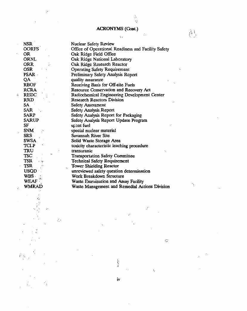
NSR Nuclear Safety Review OORFS Office of Operational Readiness and Facility Safety OR Oak Ridge Field Office ORNL Oak Ridge National Laboratory ORR ; Oak Ridge Research Reactor OSR Operating Safety Requirement PSAR Preliminary Safety Analysis Report QA quality assurance RBOF Receiving Basis for Off-site Fuels RCRA Resource Conservation and Recovery Act REDC Radiochemical Engineering Development Center RRD Research Reactors Division SA Safety Assessment SAR , Safety Analysis Report SARP Safety Analysis Report for Packaging SARUP Safety Analysis Report Update Program SF spent fuel SNM special nuclear material SRS Savannah River Site SWSA Solid Waste Storage Area TCLP toxicity characteristic leaching procedure TRU transuranic TSC " Transportation Safety Committee TSR - Technical Safety Requirement TSR , Tower Shielding Reactor USQD unreviewed safety question determination WBS ; Work Breakdown Structure WEAF Waste Examination and Assay Facility WMRAD Waste Management and Remedial Actions Division
iv
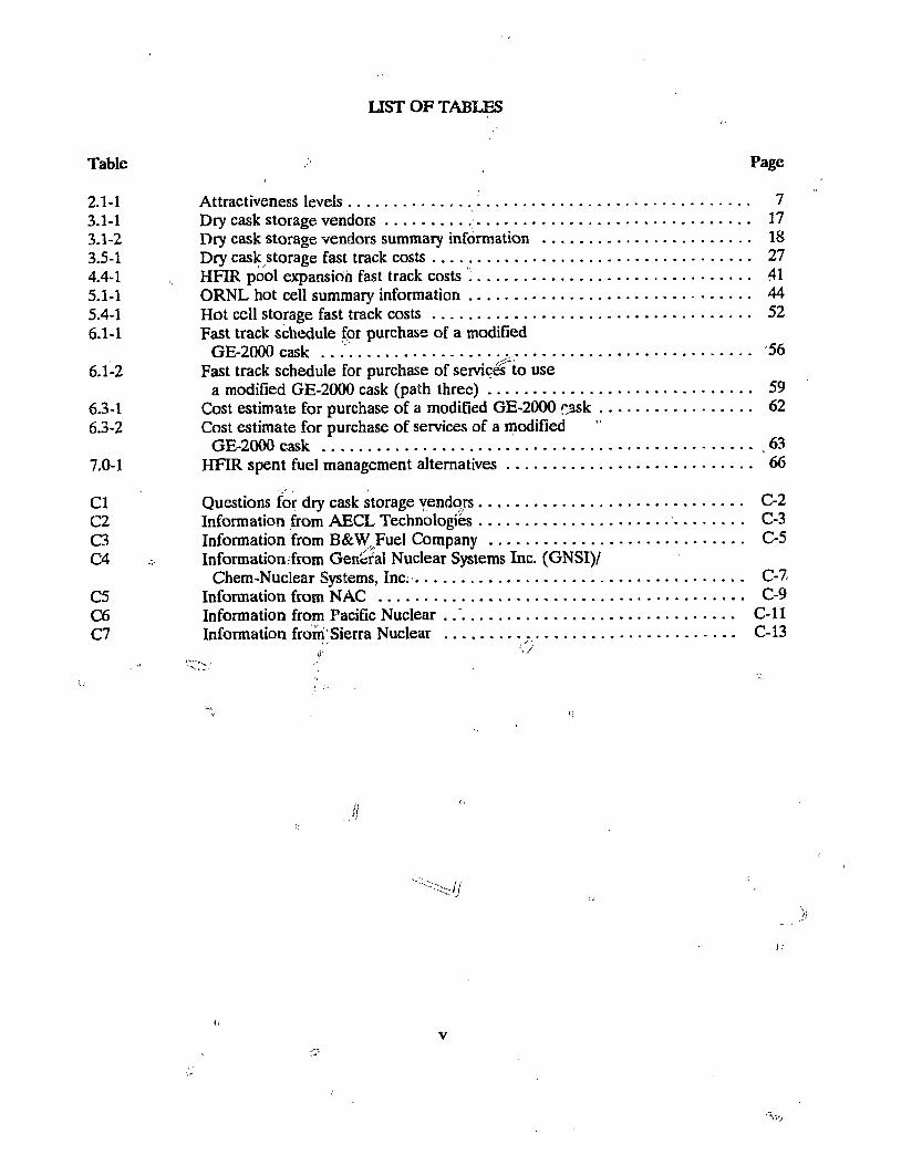
LIST OF TABLES
Table Page
2.1-1 Attractiveness levels 1 7 3.1-1 Dry cask storage vendors 17 3.1-2 Dry cask storage vendors summary information 18 3.5-1 Dry cask storage fast track costs 27 4.4-1 HFIR pool expansion fast track costs j 41 5.1-1 ORNL hot cell summary information 44 5.4-1 Hot cell storage fast track costs 52 6.1-1 Fast track schedule for purchase of a modified
GE-2000 cask . . X 56 i 1
6.1-2 Fast track schedule for purchase of services to use a modified GE-2000 cask (path three) 59
6.3-1 Cost estimate for purchase of a modified GE-2000 ^ask 62 6.3-2 Cost estimate for purchase of services of a modified
GE-2000 cask ,63 7.0-1 HFIR spent fuel management alternatives 66
CI Questions for dry cask storage vendors C-2 C2 Information from AECL Technologies C-3 C3 Information from B&WvFuel Company C-5 C4 x, Information from General Nuclear Systems Inc. (GNSI)/
Chem-Nuclear Systems, Inc. C-7 C5 Information from NAC - C-9 C6 Information from Pacific Nuclear C-ll C7 Information from'Sierra Nuclear C-13
J 'i
i. v
LIST OF FIGURES
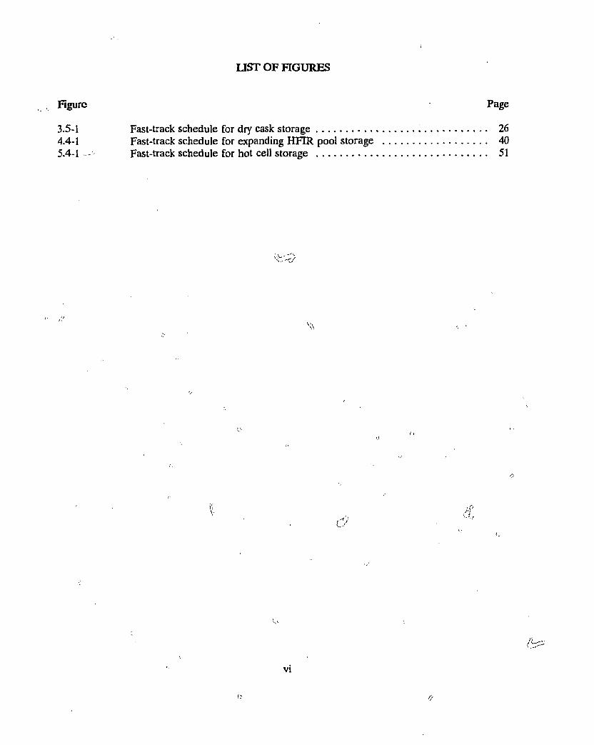
Fast-track schedule for dry cask storage Fast-track schedule for expanding HFTR pool storage Fast-track schedule for hot cell storage
O'
vi
ABSTRACT
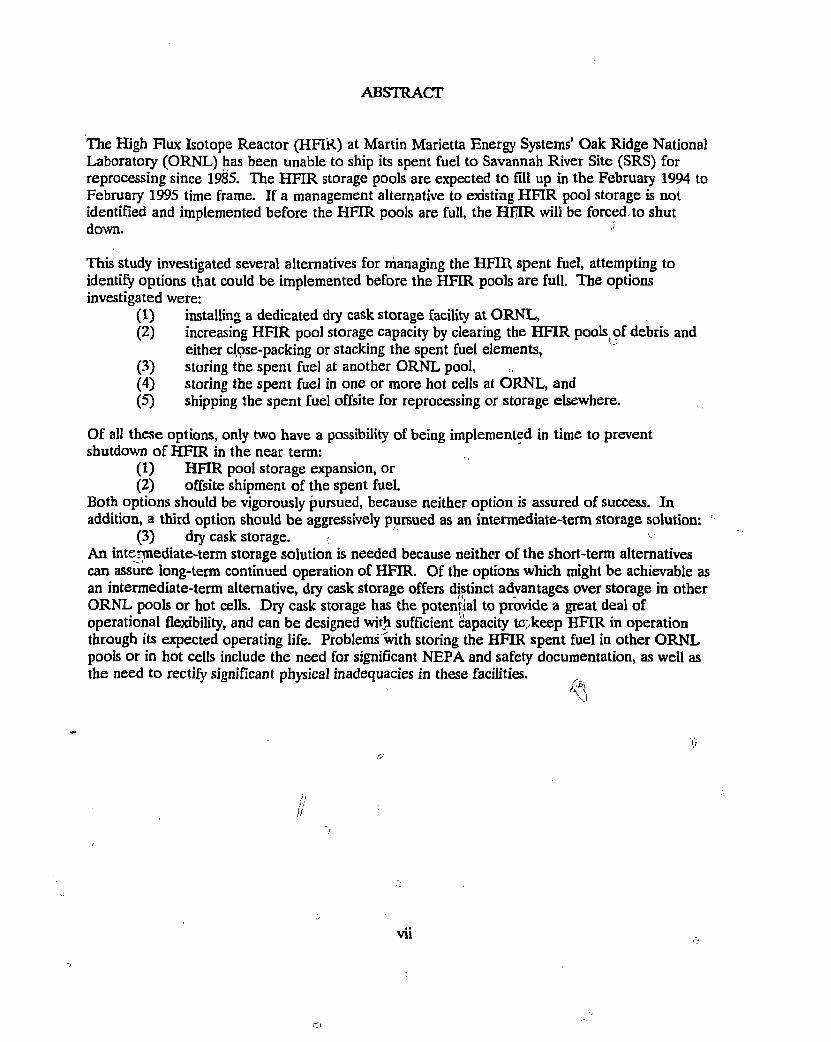
The High Flux Isotope Reactor (HFI'R) at Martin Marietta Energy Systems' Oak Ridge National Laboratory (ORNL) has been unable to ship its spent fuel to Savannah River Site (SRS) for reprocessing since 1985. The HFIR storage pools are expected to fill up in the February 1994 to February 1995 time frame. If a management alternative to existing HFIR pool storage is not identified and implemented before the HFIR pools are full, the HfjIR will be forced to shut down.
This study investigated several alternatives for managing the HFIR spent fuel, attempting to identify options that could be implemented before the HFIR pools are full. The options investigated were:
(1) installing a dedicated dry cask storage facility at ORNL, (2) increasing HFIR pool storage capacity by clearing the HFIR pools of debris and
either close-packing or stacking the spent fuel elements, (3) storing the spent fuel at another ORNL pool, (4) storing the spent fuel in one or more hot cells at ORNL, and (5) shipping the spent fuel offsite for reprocessing or storage elsewhere.
Of all these options, only two have a possibility of being implemented in time to prevent shutdown of HFIR in the near term:
(1) HFIR pool storage expansion, or (2) offsite shipment of the spent fuel.
Both options should be vigorously pursued, because neither option is assured of success. In addition, a third option should be aggressively pursued as an intermediate-term storage solution:
(3) dry cask storage. An intermediate-term storage solution is needed because neither of the short-term alternatives can assure long-term continued operation of HFIR. Of the options which might be achievable as an intermediate-term alternative, dry cask storage offers distinct advantages over storage in other ORNL pools or hot cells. Dry cask storage has the potential to provide a great deal of operational flexibility, and can be designed with sufficient capacity tc;keep HFIR in operation through its expected operating life. Problems with storing the HFIR spent fuel in other ORNL pools or in hot cells include the need for significant NEPA and safety documentation, as well as the need to rectify significant physical inadequacies in these facilities.
f/
)\
if
vii
Ci
HFIR SPENT FUEL MANAGEMENT ALTERNATIVES
1. Introduction
Martin Marietta Energy Systems' (MMES') Oak Ridge National Laboratory (ORNL) operates the
High Flux Isotope Reactor (HFIR) for the Department of Energy. This reactor discharges a full
core of spent fuel (one assembly) approximately every month. This irradiated fuel is presently
being stored in the HFIR pools until an alternative means of managing the fuel can be identified.
The HFIR pools are currently scheduled to reach their capacity to store spent fuel elements
without impairment of operations in February 1994 and to be completely full by February 1995.
- After this time, if an alternate management scheme has not been identified and implemented, the
reactor will have to be shut down.
Until a few years ago, the HFIR spent fuel was shipped to the Savannah River Site (SRS) for
reprocessing. Loss of certification on the shipping container that was used to make these
shipments has made it impossible to continue to dispose of the fuel in this manner. Efforts to
design and certify a new shipping container have so far been unsuccessful.
To assist the Research Reactors Division in determining what options are available to deal with
the HFIR spent fuel, the Chemical Technology Division was asked to conduct a study of spent
fuel management alternatives. After several discussions with RRD management, a Work
Breakdown Structure (WBS) for the effort was developed. This WBS was broken into three main
parts: (1) study of short-term alternatives, i.e., those that could be accomplished before shutdown
of HFIR, and preferably by Februaiy 1994; (2) study of intermediate-term alternatives, i.e., those
that would take more than 2 years but less than about 10 years to accomplish; and (3) study of
long-term alternatives. The last of these is the only one that would provide a permanent solution
1
to the spent fuel management problem /and vail most likely take more than ten years to
accomplish.
// A list of contacts developed during this study is given in Appendix A.
f 111/'" Task Constraints
1.1.1 HFIR Space and Time Constraints fy
As described earlier, the HFIR discharges one complete assembly per month. At this generation
rate, the reactor pools will become essentially full by February 1994. A few more spaces may be
available after this date, but their use will severely constrain operations in the pool. If these
spaces can be made available, it may be possible to extend the shutdown date to about February
1995.
These dates are predicated on two assumptions:
(1) The reactor continues to operate without interruption. Any shutdowns, such as the recent
temporary shutdown to repair the cooling water pipe leak, will extend the time it will take to fill
the pool.
(2) All of the racks currently planned for the HFIR east clean pool are successfully installed.
This will require removal of a fair amount of contaminated material now stored in the east pool.
If ORNL waste management is unable to accept this material, the shutdown date for the pool
may be significantly earlier. v
1.1.2 Other Research Reactor Needs
Several other research reactors are also thought to be running out of storage space for their spent
fuel, but the HFIR is the one with the most pressing need. These other reactor sites are also in
need of solutions to the problem of managing their spent fuel. These other reactors include the
High Flux Beam Reactor (HFBR) at Brookhaven National Laboratory (BNL), the National • •
Institute for Standards and Technology (NIST) (the old National Bureau of Standards) reactor IV
t
2
(NBSR), Omega West at Los Alamos National Laboratory, a number of university reactors, and
several foreign research reactors for which DOE is obligated to take the spent fuel.
According to Chris Wennes of BNL, BNL staff were expecting the efforts to design and build a < .
new HFIR shipping cask to provide them with a transpou-package for shipping spent fuel to the
Savannah River Site (SRS) some time soon. They will be out of space at BNL in September
1995 at their current spent fuel generation rate. If the reactor is approved for a higher power
level, this time will be shortened. An option available to them to extend their storage capacity is
to put an extra rack into their pool. This rack would allow them to operate for an additional 2
years and 4 months at the current power level, extending their operating time to January 1998.
In addition, 73 fuel elements from the Bulk Shielding Reactor (BSR) at ORNL, currently in
storage in the BSR pool, must be removed before the BSR can be permanently shut down as
directed by DOE. Transfer to the Surplus Facilities Management Program is currently scheduled
to occur in about three years' time. \
Also, the Tower Shielding Reactor (TSR) is novri in standby mode and is expected to be entering
an extended shutdown period in the future. If no long-term uses for the TSR are found then the
shutdown will, become permanent. The TSR is also unable to ship its fuel to SRS; for now its
fuel is being stored in the reactor core. 0 c.
1.2 Short-Term Alternatives Identified for Study v
A number of alternatives that might provide relief to the pool by February 1994 were identified
for study. These consist of the following:
(1) installing a dedicated dry cask)storage facility at ORNL, x
(2) increasing HFIR pool storage capacity by clearing the HFIR pools of debris and
either close-packing or stacking the spent fuel elements,
( ; (3) storing the spent fuel at another ORNL pool,
(4) storing the spent fuel in one or more hot cells at ORNL, and
(5) shipping the spent fuel offsite for reprocessing or storage elsewhere.

Each of these alternatives is discussed in subsequent sections of this report, and the feasibility of
each for management of HFIR spent fuel in the short term is assessed. First, though, a summary
of regulatory and other requirements pertinent to the spent fuel management alternatives is
provided.
U
2. Regulatory and Othdr Requirements
A significant number and variety of requirements may bs applicable to the spent fuel management
options discussed in this study. Many studies and many formal approvals to construct or to
operate may be required, depending on the option selected. This section of the report describes
the requirements which have been investigated for applicability to the HFIR spent fuel short-term
options. Later sections of the report discuss the applicability of these requirements to each spent
fuel option.
2.1 Safeguards and Security Requirements
DOE Order 5632.2A, dated February 9,1988, establishes safeguards and security requirements for
special nuclear materials (SNM). The safeguards and security requirements for a facility are
dependent on the type and quantity of special nuclear material (SNM) to be placed in the facility.
Four categories are established in this DOE Order, with Category I quantities of SNM requiring
the most stringent security measures and Category IV requiring minimal security measures. The
requirements for each category, as established in DOE Order 5632.2A, are provided in Appendix
B.
Facility classification is based on the attractiveness level and the quantity of SNM in the facility.
Attractiveness levels are defined as a "categorization of SNM material types and compositions
which reflect the difficulty of processing and handling required to convert material to a nuclear
explosive device." They range from attractiveness level A to E, with E being the least attractive.
Three of these attractiveness levels are relevant to the HFIR fuel. Attractiveness level E covers
highly radioactive SNM materials (those that, unshielded, emit a radiation dose measured at one
meter that exceeds 100 Rem/hr). HFIR spent fuel is an attractiveness level E material.
Attractiveness level D applies to moderately radioactive SNM materials (those that, unshielded,
emit'̂ a radiation dose measured at one meter that exceeds 15 Rem/hr but is not greater than 100
Rem/hr). HFIR spent fuel will eventually decay to an attractiveness level D material; however an
ORIGEN2 calculation shows that this will not occur for more than 50 years, so for the lifetime of
5
an interim storage facility the higher attractiveness level is not a concern. HFIR fresh fuel is an
attractiveness level C material. However loading the fuel into the reactor core downgrades it to
an attractiveness level E material.
For each attractiveness level of SNM, Table 2.1-1 shows what quantity of material corresponds to
each facility category. Attractiveness level E materials, as shown by this table, may be stored in
unlimited quantities in a Category IV facility. However when more than one attractiveness level
is present in a facility, the entire inventory of SNM must be treated as though it had the highest
attractiveness level for which at least 1000 grams of material is present. Text is provided at the
end of Appendix B explaining how to apply Table 2.1-1 when multiple material types or
attractiveness levels are involved.
At this time, Building 3019 is the only Category I facility at ORNL. One HFIR fresh fuel
assembly is a Category II quantity of material until loaded into the reactor core, at which time it
reverts to Category IV^ A security team is deployed at the HFIR facility until the HFIR fuel is
loaded into the reactor in response to the more stringent Category II security requirements. All
other ORNL facilities are Category III or less. The safeguards and security requirements increase
significantly when going from Category III to Category II. Should a Category II quantity of SNM
be stored in another ORNL facility, major physical security upgrades to the facility would be
required and additional protective force manpower (i.e., approximately 8 FIEs) would have to be
hired.
Because the HFIR spent fuel is an attractiveness level E material and will remain so for the
conceivable lifetime of an interim storage facility, safeguards and security requirements will
increase with the addition of HFIR spent fuel only if 1000 grams or more of a SNM with a higher
attractiveness level is already present in the facility under consideration. As will be discussed in
Section 4 of this report, the Bulk Shielding Reactor (BSR) pool contains approximately 4000
grains of attractiveness level D material, which severely restricts the amount of HFIR spent fuel
which could be placed in this pool without upgrading the BSR to a Category II facility.
6
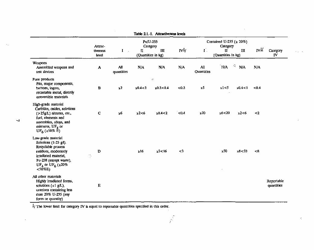
Tabic 2.1.-1. Attractiveness levels
Pu/U-233 Contained U-235 (2 20%) Altrac- Category _ Category tiveness I I I I I I IV-V I I I I I I I V ^ Category
level (Quantities in kg) (Quantities in kg) I V
Weapons Assembled weapons and test devices
Pure products Pits, major components, buttons, ingots, recastable metal, directly convertible materials
High-grade material Carbides, oxides, solutions (>25g/L) nitrates, etc., fuel, elements and assemblies, alloys, and mixtures, UF^ or U F f i ( *50% E)
Low-grade material Solutions (1-25 g/1). Recyclable process residues, moderately irradiated material, Pu-238 (except waste), U F 4 or U F 6 ( *20% <50%E)
All other materials Highly irradiated forms, solutions (s 1 g/L), uranium containing less than 20% U-235 (any form or quantity)
B
All quantities
i2
N/A
i0 .4<2
N/A
i0.2<0.4
N/A
<0.2
All Quantities
'N /A
i l < 5
N/A N/A
*0.4<1 <0.4
2 6 i2<6 *0.4<2 <0.4 iZO *6<20 i2<6 <2
2 I 6 i 3 < 1 6 <3 *50 28<50 < 8
Reportable quantities
1/ The lower limit for category I V is equal to reportable quantities specified in this order.
2.2 NEPA Requirements
DOE's National Environmental Policy Act (NEPA) Implementing Procedures were published in '
the Federal Register on April 24, 1992. This new 10 CFR 1021 provides guidelines for
determining whether an Environmental Assessment (EA) or an Environmental Impact
Statement(EIS) is required for an action. The regulation was reviewed for guidance pertaining to
spent fuel storage.
Appendix D to Subpart D describes classes of actions that normally require EISs. Item D10 in
this appendix is titled "Siting/construction/operation of major high-level waste treatment, storage,
disposal facilities," which is described as "Siting, construction, operation, and decommissioning of
major treatment, storage, and/or disposal facilities for high-level waste and/or spent nuclear fuel,
such as spent fuel storage facilities and geologic repositories." The regulation does not provide
guidance as to what is considered a "major" facility. It seems likely that this requirement would
pertain to a monitored retrievable storage (MRS) facility, designed to store large quantities of O
spent fuel destined for geologic disposal. Whether or not it would apply to a new HFIR spent
fuel storage, facility, such as a dry cask storage facility, is not clear.
Requirements pertaining to EAs were reviewed for guidance. Appendix C to Subpart D of this
regulation describes classes of actions that normally require EAs but not necessarily EISs. Item
C16 in this appendix is titled "Siting/construction/operation of onsite waste storage facilities (not
high-level, spent nuclear fuel)," which is described as "Siting, construction (including modification
to increase capacity), operation, and decommissioning of onsite storage facilities and/or packaging
and unpacking facilities (that may include characterization operations) for all waste other than
high-level waste or spent nuclear fuel" (except for storage of packaged hazardous waste in satellite
accumulation areas, which are categorically excluded from NEPA documentation requirements).
Since spent fuel was specifically excluded from this description, a greater level of documentation
is implied for a spent fuel storage facility; but whether a more in-dopth EA would suffice or
whether an EIS would be necessary is not known.
Westinghouse Hanford Company is pursuing construction of an interim dry cask storage facility
and is proceeding on the basis that an EA will suffice, per a conversation with Mike Jensky,
8
Westinghouse Hanford Co. NEPA Coordinator. As long as the quantity of fuel to be stored is
limited (to what maximum quantity is not known), the storage period is limited (to perhaps 20
years, though this is not known for certain), and the facility will be located on an already
developed site, a case may be made for an EA as opposed to an EIS.
To obtain a definite ruling from DOE, an Environmental Assessment Determination (EAD) must
be written describing the exact scope of the project and recommending an E A The EAD is
submitted to DOE/HQ and must be approved by the Assistant Secretary. This approval process
can take as little as 2 weeks but typically takes approximately 6 months. It has taken as long as
lVa years. The EAD may come back approved for an EA, or it may come back requiring an EIS.
DOE rules state that work may not officially begin on an EA before this approval is received
from DOE/EH.
For the HFIR pool, since HFIR spent fuel is already stored in the pool, it may be possible to
obtain a Categorical Exclusion (CX) for reracking the pool to obtain additional storage capacity.
A CX means that no further NEPA documentation (EA or EIS) is required.
For an existing facility not already storing this type of material, it is likely that an EA will be
required to cover transport to the facility anVi storage in the facility. However this case is not
explicitly covered in DOE's new NEPA regulations. To obtain a formal ruling from DOE on
what NEPA documentation will be required for such an action, an Action Description
Memorandum (ADM) should be prepared and submitted to DOE, fully describing the planned
activity and asking what NEPA documentation is needed. Whereas an EAD is written to ask for
confirmation that an EA is appropriate, the ADM is written asking for guidance. Both take
about an equivalent amount of time (usually about 6 months) for response from DOE.
DOE/EH and the State of Tennessee are both involved in the review and concurrence process for
an EA. Initial preparation of an EA generally costs S80K-100K, but the cycle of reviews and
revisions can easily double that cost. Although no real experience has yet been gained by ORNL
on the length of time required to get an EA approved (ORNL has submitted numerous EAs but
has not yet had an EA approved), it is believed that two years or more would typically be needed.
When asked whether this time could be shortened, an example was given of a very high priority
9
EA effort, for Nuclear Fuel Services (NFS) Pu scrap and waste shipments, which has been in the • i
review and revision process for close to two years now and is not yet approved. It does not
appear that a significant shortening of the review process could be achieved without a great deal
of political pressure at the DOE/HQ level. '1
H A possible response to an EA submittal is a requirement that an EIS be prepared. Thus an early
ruling from DOE that an EA will suffice does not guarantee that an EIS will not eventually be
required.
Recently ORNL has learned that EM is about to release a subcontract to prepare a programmatic
EIS for the interim storage of DOE high-enriched spent fuel. Projects cannot proceed if the
project can impact the record of decision of the programmatic EIS. How this will impact HF1R
spent fuel management alternatives is yet to be determined. v
Construction of a new facility may not begin until a finding of no significant impact (FONSI) is
received from DOE, or until an EIS is approved. In fact approval from DOE must be formally
requested and granted to proceed as far as Title 1 design before a FONSI has been received; ri
An EIS, if required, must be contracted out to an independent (non-ORNL) organization. Public
hearings are part of the EIS review and approval process. ORNL does not yet have experience ,
with the public hearings process, so the actual length of time an EIS might require is not known.
A guess is that an EIS would probably take 3 to 5 years (possibly more) and cost at least $1M.
2.3 RCRA Requirements
The Resource Conservation and Recovery Act (RCRA) regulations of the Environmental
Protection Agency (EPA) place extremely stringent requirements on storage and disposal facilities
for hazardous wastes. As long as the HFIR spent fuel storage facility does not contain any
RCRA wastes, these regulations will not apply. The HFIR spent fuel does not appear to contain
any of the RCRA listed wastes, nor does it appear to meet any of the characteristics of hazardous
waste (ignitability, corrosivity, reactivity, or toxicity); however this should be formally evaluated
and documented.
- I io V
Cadmium is a toxic material subject to the toxicity requirements. Therefore the HFIR cadmium
shrouds could become a RCRA issue if placed in the HFIR storage facility. The shrouds could
be included in the HFIR spent fuel storage facility either as part of the facility (for criticality
control) or as wastes. If included as part of the facility (i.e., not to be disposed of), RCRA
requirements would not apply to the cadmium shrouds. If considered part of the waste (i.e.,
stored for eventual disposal), the shrouds would have to, be shown to pass the toxicity
characteristic leaching procedure (TCLP) test required by RCRA (40 CFR 261 Appendix II) to
be excluded from RCRA requirements.
RCRA requirements would place a significant burden on a HFIR spent fuel storage facility. If
RCRA applied, facility construction could not begin until an EPA Part B permit was in hand. A
year or more is generally required to obtain a Part B permit from the State of Tennessee. The
permit application would have to include engineering drawings and information on how the
facility would be operated, as well as information on the waste and the containers to be used.
More significant than this requirement is the effect that RCRA requirements would have on
facility design. No precipitation may fall within a RCRA facility; therefore a tent or .roof would l j •:
be required over the storage facility. Requirements pertaining to security, communications and
alarm systems, fire control equipment, spill control equipment, decontamination equipment, and
aisle space are spelled out in 40 CFR 264.14 to 264.35. Subpart I, starting at 40 CFR 264.170,
spells out requirements for use and management of containers in a RCRA facility. A base must
underly the containers which is free of cracks or gaps and is essentially impervious to leaks or
spills. The base must be sloped or the containment system must be otherwise designed and
operated to drain and remove liquids resulting from leaks, spills, or precipitation (unless the
containers are elevated) so that the liquid may be analyzed. Run-on into the containment system
(i.e., rain or other water source running into the facility) must be prevented unless excess capacity
to contain the run-on is provided.
If the HFIR spent fuel is placed in storage casks which are considered nonportable, then Subpart
J covering tank systems (starting at 40 CFR 264.190) applies. These requirements are too lengthy
to be listed here. One of the requirements is for a secondary containment capable of containing
the entire contents of the largest tank (i.e., storage cask) within its boundary. Emergency alarms
11
for a breach of the primary containment are also required. Where possible in a facility design,
efforts are generally made to avoid being classified as a tank system by ensuring that the
containers within that facility are portable. i j
2.4 Transportation Requirements
To transport HFIR spent fuel, it is important to know whether the movement will occur entirely
onsite or whether some part of the movement will require the spent fuel to go offsite. As long as
the movement remains entirely onsite, Department of Transportation (DOT) regulations do not
apply to the movement. The moment that a shipment leaves the controlled access areas of the
ORNL reservation, DOT regulations apply.
To move the spent fuel offsite, DOT regulations require that the fuel be transported in a shipping
container certified by either the DOE or the Nuclear Regulatory Commission (NRC) to carry
HFIR spent fuel. At this time, no shipping container is certified by either of these organizations
to carry HFIR spent fuel. Therefore the HFIR spent fuel cannot be transported offsite.
Efforts are underway to obtain a DOE- or NRC-approved shipping container for the HFIR spent
fuel. When these efforts might be successful is not known. This subject is discussed further in
Section 6.0 of this report.
To transport the HFIR spent fuel onsite, ORNL procedures require that the movement be made
in accordance with ORNL's Onsite Transportation Operations Manual. Use of the decertified
HHR spent fuel shipping container is acceptable for onsite movements at this time, if appropriate ll
arrangements-are made and approvals are obtained. Approvals for making onsite movements with
decertified containers are fairly straightforward. A document would have to be prepared
describing the planned transport activities and demonstrating that the movement would be
performed in a safe manner. This evaluation would have to be reviewed and approved by
appropriate ORNL organizations, in particular the Transportation Safety Committee (TSC) and
the ORNL Transportation Manager. Roughly one to two man-months of effort would typically
be required to document the planned transport activities, review them before the TSC, and revise
the document.
12
DOE/HQ has discussed the possibility of placing more stringent requirements on onsite
movements, possibly even requiring that they be made in accordance with offsite regulations, but
whether or not this will ever come to pass is uncertain. Most DOE facilities would be ill
equipped to comply with such a requirement. Such a requirement is not expected any time soon,
because of the inability of DOE facilities to comply with it in the foreseeable future.
2.5 j ;.*ocumentation Requirements ' f"'
*--<-. - /
Until very recently, safety documentation requirements were established in DOE Order 5481.1B,
"Safety Analysis and Review Systems," dated September 23, 1986. However, for all nuclear
facilities, a new DOE Order 5480.23, "Nuclear Safety Analysis Reports," dated April 30, 1992, has
replaced the requirements of 5481. IB; this new order was incorporated into the contract between
MMES and DOE as of the "end of September 1992. This new DOE order leaves safety
documentation requirements in a state of flux. Although an attempt has been made to document
the latest requirements, interpretations of these new requirements are subject to change.
The safety documentation process begins .with preparatioK of a Safety Assessment (SA). This-.is
true for construction of a new facility as well as for expanded use of an existing facility. The SA • - v
includes a hazard screening for the facility, which establishes the amount of additional safety '
documentation required. For an existing facility, the SA would also have to include an <
unreviewed safety question determination (USQD), evaluating the impacts of the proposed
modification on the facility. An SA can typically be produced in a few months and generally costs
$10I'-30K. (j ^
The hazard screening is based on the type and quantity of hazardous material (toxic and
radioactive) to be present at the facility. It does not take into account any features of the facility
that might mitigate the hazard. The hazard screening is expected to classify a facility containing
HFIR spent fuel as a moderate hazard, though an analysis is required to make an absolute
determination. According to the MMES Safety Analysis Report Update Program Hazard
Screening Application Guide. Report Number ES/CSET-2/R1, dated June 1992, low hazard
facilities are those which present minor onsite and negligible offisite impacts to people or to the
environment. This translates to a reversible health effect to a few people onsite, and a negligible
u
health effect offsite. Moderate hazard facilities are those which present considerable potential
onsite impacts to people or to the environment, but at most only minor offsite impacts. This v
translates to an irreversible health effect to a few people onsite and/or a reversible health effect \,
to a few people offsite. A negligible radiological health effect is defined as less than 10 rem; a
reversible health effect, 10 - 100 rem; and an irreversible health effect, greater than 100 rem.
Before a moderate hazard material may be placed into an existing facility, it is fairly certain that a
Safety Analysis Report (SAR) for the entire facility will have to be written and approved,
including the moderate hazard material in its scope. Writing the SAR would typically require 1 to
5 years, depending on the complexity of the facility and the availability of detailed information
about the facility (such as as-built drawings and descriptions of hazardous contents). The cost of
an SAR might range from $1M to $5M or more. The new DOE Order 5480.23 implies that
DOE/HQ must now approve SARs for moderate or high hazard facilities; however DOE/HQ
does not yet have a mechanism in place for reviewing and approving SARs. Therefore the time
required to obtain DOE/HQ approval is not known. A guess has been suggested of 6 months to
2 years for SAR approval, though it could potentially take much longer. No SARs written to
current requirements (since the SARUP program was implemented in about 1990) have yet been
approved by DOE/HQ.
Two real concerns with existing facilities are that (1) not enough information may exist on the
facility to produce a credible SAR, or (2) the- facility may not meet today's safety standards.
Considerable physical modification effort may be needed to upgrade an older facility to ensure
that it meets current safety standards. It may not realistically be achievable to upgrade some
facilities sufficiently that they could meet current requirements for a moderate hazard facility.
For a new moderate hazard facility, a SAR must also be prepared and approved by DOE before
spent fuel can be placed in the facility. However SAR preparation is a great deal easier and less
expensive for a new facility, because a new facility can be designed to today's safety standards and
appropriate supporting documentation and analyses can be provided as part of the design process
to ensure that the resulting design will be adequate. For a dry cask storage facility, if an NRC
license and supporting safety documentation were required of the cask vendor, supporting safety
documentation should be very straightforward to prepare. It may even be possible to use the
NRC-approved safety documentation to satisfy a large part of the SAR requirements. ORNL has
no experience in getting DOE to accept NRC safety documentation, but ORNL staff have begun
exploring this possibility with DOE/OR. At this time, DOE/OR, ER, NE, and EM appear
receptive to the idea of accepting an NRC license. / ,
• )
On a line item project for a moderate or high hazard facility, a Preliminary Safety Analysis Report
(PSAR) must be prepared and approved by DOE before construction can begin. Realistically,
most of the PSAR work is done during the conceptual design phase of the project. The cost of
preparing the PSAR (typically a few hundred thousand to a million dollars) would somewhat
reduce the cost of producing the Final Safety Analysis Report (FSAR) for the facility. As
mentioned earlier, the SAR must be approved before operation can begin.
For any near-term activity involving significant facility modification or new construction, the time
required to get the safety documentation approved is the most significant concern.
2.6 Nuclear Criticalitv Safety Requirements
According to the ORNL Health Physics Manual Sections RP-2.4 and A-14, any handling of
fissionable materials must be analyzed and reviewed for criticality concerns. This process is //
termed a Nuclear Safety Review (NSR). The NSR consists of an analysis performed by the
operating organization and peer reviewed by ORNL's nuclear criticality safety organization. At
this time, ORNL's Office of Operational Readiness and Facility Safety (OORFS) is the ultimate
approval authority for the NSR. DOE does not approve the criticality review unless it involves a
change to an SAR or to a Technical Safety Requirement (TSR) document (formerly called an
Operating Safety Requirement [OSR] document).
The approval authority is changing. DOE Order 5480.24, signed August 12, 1992, is a new A
criticality safety order which has just been) incorporated into the MMES contract. This order may
require approvals at DOE/HQ; the approvals may be a part of the SAR approval process. The
draft order was subject to a great deal of interpretation and OORFS has not yet seen the final
order, so details of the impact of this order are not well understood. Once implementation of the
order is formally required of MMES, ORNL should have 6 months to come into compliance.
15
3. Dry Cask Storage Alternative
3.1 Description of Dry Cask Storage
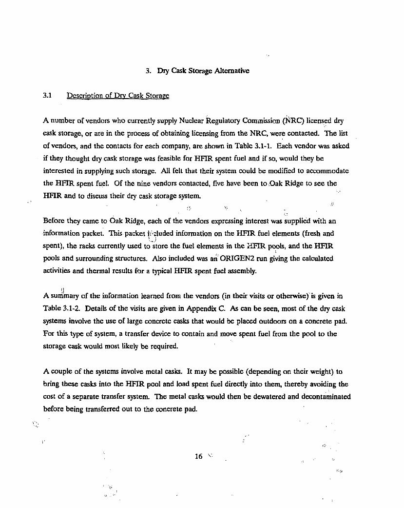
i. A number of vendors who currently supply Nuclear Regulatory Commission (NRC) licensed dry
cask storage, or are in the process of obtaining licensing from the NRC, were contacted. The list
of vendors, and the contacts for each company, are shown in Table 3.1-1. Each vendor was asked
if they thought dry cask storage was feasible for HFIR spent fuel and if so, would they be
interested in supplying such storage. All felt that their system could be modified to accommodate
the HFIR spent fuel. Of the nine vendors contacted, five have been to Oak Ridge to see the
HFIR and to discuss their dry cask storage system.
O v
Before they came to Oak Ridge, each of the vendors expressing interest was supplied with an
information packet. This packet included information on the HFIR fuel elements (fresh and
spent), the racks currently used to store the fuel elements in the HFIR pools, and the HFIR
pools and surrounding structures. Also included was an ORIGEN2 run giving the calculated
activities and thermal results for a typical HFIR spent fuel assembly.
A summary of the information learned from the vendors (in their visits or otherwise) is given in
Table 3.1-2. Details of the visits are given in Appendix C. As can be seen, most of the dry cask
systems involve the use of large concrete casks that would be placed outdoors on a concrete pad.
For this type of system, a transfer device to contain and move spent fuel from the pool to the
storage cask would most likely be required.
A couple of the systems involve metal casks. It may be possible (depending on their weight) to
bring these casks into the HFIR pool and load spent fuel directly into them, thereby avoiding the
cost of a separate transfer system. The metal casks would then be dewatered and decontaminated
before being transferred out to the concrete pad.
16 v.
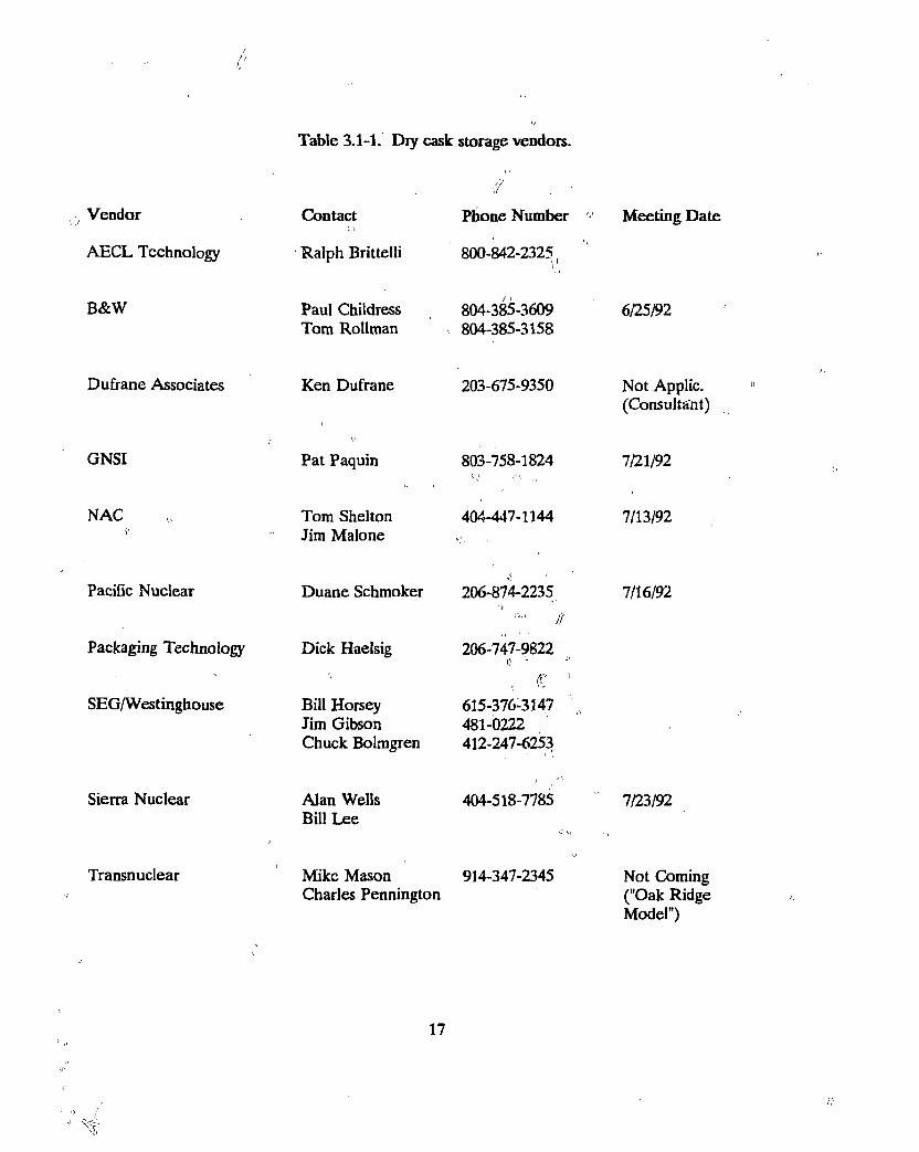
Table 3.1-1. Dry cask storage vendors.
Vendor
AECL Technology
B&W
Dufrane Associates
GNSI
NAC V
Pacific Nuclear
Packaging Technology
SEG/Westinghouse
Sierra Nuclear
Transnuclear
Contact 1.1
Ralph Brittelli
Paul Childress Tom Rollman
Ken Dufrane
Pat Paquin
Tom Shelton Jim Malone
Duane Schmoker
Dick Haelsig
Bill Horsey Jim Gibson Chuck Bolmgren
Alan Wells Bill Lee
if , " Phone Number
800-842-2325.
804-385-3609 804-385-3158
203-675-9350
803-758-1824
404-447-1144
Meeting Date
206-874-2235 ft
206-747-9822 i> -f *
u 615-376-3147 481-0222 412-247-6253
404-518-7785
6/25/92
Not Applic. (Consultant)
7/21/92
7/13/92
7/16/92
Mike Mason 914-347-2345 Charles Pennington
7/23/92
Not Coming ("Oak Ridge Model")
17
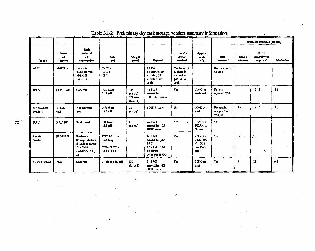
Table 3.1-2. Preliminary diy cask storage vendors summary information
< Estimated acfccdale (Boatfe)
Veador
N u t of
S^fltCB
Banc aalerial
at lUMllllIlM
Size (ft)
Wrigjtt ( H Piytoad
Traaffer •• device
requited
Appro*, c n k <*)
NRC Uceaoed*
Deng* cfcaaga
NRC A a e ^ T n t
appnws! Fabricstioa
AECL MACStor Concrete monolith vault with CS. canisters
27 W x 80 L x 21 T
12PWR assemblies per canister, 24 canisters per vault
Yes-to move canister in and out of pool & to vault
No-licensed in Canada
B&W CONSTAR Concrete 10.2 diam 21.3 tall
145 (empty) 171 max (loaded)
32 PWR assemblies -35 HFIR cores
Yes 500K for each cask
Not yet, expected 2/93
12-18 4-6
GNSI/Chem Nuclear
VHLW cask
Nodular cast iron
3.75 diani 11.3 tall
21 (empty)
3 HFIR cores No 300K per cask
. No, similar ' design (Castor
V/21) is
5-6 14-16 4-6
NAC NAC-S/T SS A Lead 7.8 diam 15.1 Ull
81 (empty)
26 PWR assemblies -25 HFIR cores
Yes 1.5M lor FOAK at Surrey
Yes 12
Pacific Nuclear
NUHOMS Horizontal Storage Module (HSM)-concrete Diy Shield Canister (DSC)-s s
DSC:5.6 diam 15.5 long
HSM: 9.7W x 18.1 L x 15 T
24 PWR assemblies per DSC 1 DSC/1 HSM 10 HFIR cores per HSM?
Yes 400K for each DSC & HSM for PWR use
Yes 12 y i
Sierra Nuclear VSC Concrete 11 diam x 18 Ull 130 (loaded)
24 PWR assemblies -12 HFIR cores
Yes 300K per cask
Yes 6 12 6-8
Any type of cask or transfer device which might be used directly in the HFIR is limited to 50 tons
maximum gross weight. This is the capacity of the HFIR crane and surrounding structure
(including the floor loading).
A study of the costs involved with each type of system (large concrete cask with transfer device
versus small metal cask that can be loaded directly) will have to be performed to determine which
is the most economical.
Dry cask storage systems are currently being offered commercially and are being installed at a
number of utilities needing additional spent fuel storage space. Advantages are that these systems
are designed to safely handle spent fuel from the beginning of the design and are not retrofits to
existing facilities (avoiding the constraints such retrofits inevitably require). The casks contain
passive heat removal systems which negate the need for active cooling systems. Coupled with
these passive heat removal systems, the casks have enough shielding to keep surface dose rates to
very low levels. This allows utilities to place the loaded casks on the concrete pads with just a
fence around them. Continuous surveillance of the casks is not required. Dry cask storage can
be set up in a modular fashion, with additional casks added as more spent fuel is removed from
the HFIR. This offers considerable flexibility in the future continuous operation of the HFIR.
The belief that purchasing an NRC-licensed package from the vendor would greatly reduce the
safety analysis and documentation costs, as well as approval uncertainty, is a further advantage.
Disadvantages of the systems include the fact that all current systems would require modification
to accommodate HFIR spent fuel with NRC approval of such modifications. The costs may be
higher than desired, and such a system probably cannot be ready by February 1994. In addition,
dry cask storage is also only a temporary solution, in that the spent fuel will still need to be
moved at a later date — either for reprocessing or to a permanent repository.
19
3.2 Siting Options Investigation
Sites investigated for placement of the concrete pads and storage casks included one adjacent to
Building 7900 (HFIR building) and sites in the current and planned Solid Waste Storage Areas
(SWSAs).
3.2.1 Adjacent to Building 7900
The hillside east of 7900 that leads downward from the building towards the cooling towers is the
preferred site. By placing the concrete pad adjacent to the HFIR, transportation of the storage
cask or transfer device will be minimized. In addition, it may be possible to use the natural
terrain to allow for easy emplacement of the spent fuel into the storage casks (i.e., load into the
top of the casks from the roadside above the site that runs out from the truck ramp access to
Building 7900).
Discussions to date have not revealed any buried pipes or other lines to exist in this hillside. Part
of the hill just east of Building 7900 has recently been excavated to find and repair a leak in the
cooling water lines. By moving approximately 60 feet east of the truck ramp access, all buried
lines can be avoided.
No other uses for this area have currently been identified. A maintenance building was proposed
at one time, but this is no longer being considered per Walt Brown of RRD. The ORNL Space
Coordinator (S. R. McNeany) was aware only of the possible maintenance facility.
3.2.2 Solid Waste Storage Area
Four SWSAs were considered in discussions with the Waste Management and Remedial Actions
Division (WMRAD).
SWSA 5 South is not a candidate because it has been turned over to DOE-Environmental
Restoration and Waste Management (EM).
20
SWSA 5 North is not a candidate because it is limited to storage of contact-handled transuranic
(CH-TRU) waste with some low-level waste (LLW). This is where the plutonium contaminated
waste from Nuclear Fuel Services in Erwin, TN will be placed.
SWSA 6 is not a candidate because it is reserved for LLW disposal and is due to begin closure in
FY 1993. Closure should be complete by FY 1997 for all except the IWMF (Interim Waste
Management Facility).
This leaves only SWSA 7, which is still to be constructed, as a possibility. CH-TRU waste is to be
included in SWSA 7, as well as Class III/IV (above/below grade). The Central Waste
Management Division (CWMD) Class II Tumulus concept, which involves placing LLW in
concrete casks on a concrete pad and then placing earth on top to form a mound, is also planned
for construction in this area. The HFIR spent fuel would probably be stored as Class III above
grade storage material.
Given that much of SWSA 7 is already committed, WMRAD would prefer to see HFIR spent
fuel stored within the fenced area around the 7900 area. By avoiding the SWSAs, transportation
on the ORNL reservation can be minimized.
3.3 Regulatory and Other Requirements
3.3.1 Safeguards and Security Requirements
As described in Section 2.1, the HFIR spent fuel is an attractiveness level E material. Therefore
an unlimited amount could be stored in a dry cask storage facility with minimal safeguard and
security requirements. Further, the attractiveness level of the material would not increase over
the expected lifetime of the dry cask storage facility. As pointed out in Section 2.1, the HFIR
spent fuel would still be classified as an attractiveness level E material after 50 years of decay.
21
3.3.2 NEPA Requirements
NEPA requirements are summarized in Section 2.2 of this report. These requirements are
expected to have significant impacts on HFIR spent fuel management alternatives.
Construction of an interim dry cask storage facility for the HFIR spent fuel is expected to require
significant NEPA documentation, probably an EA and possibly an EIS, as explained in Section 2.2
of this report. Westinghouse Hanford Company is pursuing an EA route for their planned dry
cask storage facility but has not yet had a response from DOE on the acceptability of this route.
ORNL staff familiar with NEPA requirements recommended pursuing an EA based on the
interim nature of the facility. Preparation, submittal, and response for an EAD, as explained in
Section 2.2, could take 6 months or more. Preparation, review, and approval of the EA could
then take two years or more. In all this time, design work could not proceed on the project. A
great many ORNL projects are reportedly on hold due to the long times required to obtain
approved NEPA documentation. Due to the critically short time in which a storage alternative
must be put in place, the NEPA documentation requirements make dry cask storage look
unfavorable as a short-term management alternative. However as an interim storage alternative,
dry cask storage has significant advantages over other management alternatives investigated.
3.3.3 RCRA Requirements
Assuming the conditions stated in Section 2.3 of this report can be met, RCRA regulations would
not apply to any of the hot cell storage options.
3.3.4 Transportation Requirements
The sites under consideration for the dry cask storage facility are on the ORNL reservation and
may be reached without any offsite transport. Therefore a certified shipping container would not
be required for the movements, as discussed in Section 2.4. As mentioned in Section 3.1, some
means for transferring the HFIR spent fuel elements to the dry storage casks, or transporting the
22
dry storage casks to the HFIR fuel elements for loading and transport to the storage pad, will
have to be developed as part of the design effort.
3.3.5 Safety Documentation Requirements
As explained in Section 2.5 of this report, safety documentation requirements for a new facility
typically start with a SA. During the design phase, and before construction can begin, a PSAR
has to be written and approved. Then before the facility can begin operation, an FSAR has to be
written and approved. For a moderate hazard facility, which this is likely to be, approval by
DOE/HQ is now required for the safety documentation.
The dry cask storage facilities being investigated have the option of being licensed by the NRC.
To obtain an NRC license, a SAR covering the dry cask storage design has to be submitted to the
NRC for review and approval. The SAR supporting the license application would be written
from the perspective that the dry cask storage system could safely be built and operated at any
NRC-licensed site.
By requiring that the vendor secure an NRC license for the dry cask storage facility, it may be
possible to circumvent some of the DOE safety documentation requirements. ORNL staff
involved in the safety documentation area have begun pursuing with DOE/OR the possibility of
substituting the SAR required to support NRC licensing activities for part or all of the DOE SAR
requirements. Reactions so far from DOE organizations approached on this subject have been
favorable. DOE may desire some site-specific documentation in addition to the generic NRC-
approved SAR, or they may require an entirely new SAR. Even if the latter is true, the NRC-
approved SAR should significantly reduce the time and funding required to prepare a SAR for
DOE.
3.3.6 Nuclear Criticality Safety Requirements
As explained in Section 2.6, the nuclear criticality safety requirements are in a state of flux. It is
believed that these requirements will be incorporated into SAR documentation requirements in
23
the near future. A nuclear criticality evaluation will be required as a part of the NRC licensing activities for dry cask storage.
3.4 Feasibility of ORNL Dry Cask Storage as Short-Term Alternative
Dry cask storage does not appear feasible as a short-term (less than two years) alternative. The
long times required to complete NEPA documentation!, design, licensing, fabrication, and safety
documentation make it impossible to implement a dry'cask storage alternative before the current
planned spent fuel storage array at HFIR is full. However as an intermediate-term (two to ten
years) alternative, dry cask storage looks very promising. It has significant advantages over the
hot cell storage alternative in that, as a new design and construction activity, safety documentation
does not have to be backfitted to a.potentially inadequate design. Thus the possibility of
significant unplanned costs associated with upgrading an existing facility can be avoided. In
addition, the opportunity to rely on NRC-approved safety documentation may significantly reduce
the time required to prepare, review, and receive approval for a DOE SAR, if one is required.
For both these reasons, the potential for success is much greater with the dry cask storage
alternative than with any other alternative.
3.5 Cost and Schedule Estimates
Approximate costs from the dry cask storage vendors are shown in Table 3.1-2. These costs, as
well as all the other information, should be regarded as very preliminary. This is because, in most
cases, the information was provided by marketing people with only a limited amount of
preparation. Considerably more study will be{ required by each vendor before realistic costs can
be determined.
Having said that, it is evident from Table 3.1-2 that unit costs for dry cask storage depend
considerably on the capacity of a cask and on the costs of any transfer devices which might be
required.
The unit costs, in thousands of dollars per HFIR spent fuel assembly, range from $14K for the
B&W system to $100K for the GNSI system. This neglects the costs of the concrete pad and
24
outside handling system, as well as any required transfer device. In fact, the GNSI system would
not require a transfer system, while the B&W system would. The costs of such a transfer system
were variously estimated as between 1 to 3 million dollars. Thus neither unit costs or only initial
capital costs will be sufficient to determine the most economical system. Instead, total life cycle
costs will need to be estimated.
It would appear that about $1M per year will be required in operating expenses once the initial
capital outlays are made.
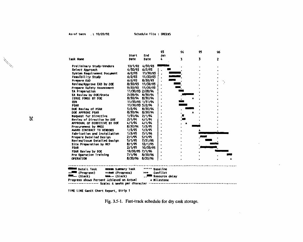
Figure 3.5-1 presents a fast-track schedule for providing interim dry cask storage. Table 3.5-1
presents associated costs. As stated previously, this option is not achievable in the short
term,even on a fast-track schedule. In the intermediate term, however, this option looks very
favorable compared to other alternatives investigated.
The fast-track schedule makes several assumptions. If any of these assumptions cannot be
implemented, the schedule will be delayed accordingly. First, the schedule assumes that an EA
will be required rather than an EIS, and that it can be written in 3 months and approved by DOE
and the state in 6 months. This short a review schedule has never been achieved. Typically two
or more years are reportedly required to obtain DOE and state approval.
If an EIS is required, a very optimistic schedule (i.e., one that has never been achieved) would < <
call for 1 year and $1M for initial preparation of the EIS, and 1 year for review and approval plus
$0.5M for revisions. More realistically 3 to 5 years or more would be expected to write and
obtain approval of an EIS.
Similarly optimistic estimates have been made for safety documentation activities, based on the
assumption that the NRC-approved SAR for the dry cask storage facility would significantly
reduce the DOE SAR writing, review, and approval process.
Another assumption is that Accelerator Reactor Improvement and Modification (ARIM) funding
will be available to fund this activity. If this were a line item project, 1997 would be the earliest
that funding could be made available to support this work.
25
fcs-of Det- : 10/20/92 Schedule FiVe : GREENS
Task Nam
Preliminary Study-Vendors Select Approach System Requirement Document Feasibility Study Prepare EAD Review/Approve EAD by DOE Prepare Safety Assessment EA Preparation EA Review by DOE/State ISSUE FONSI BY DOE COR PSAR DOE Review of PSAR DOE APPROVE PSAR Request for Directive Review of Directive by DOE APPROVAL OF DIRECTIVE BY DOE Procurement by HMES AWARD CONTRACT TO VENDORS Fabrication and Installation Prepare Detailed Design Review/Issue Detailed Design Site Preparation by MICF FSAR FSAR Review by DOE Pre Operation Training OPERATION
93 Start End Jan Date Date 4
10/1/92 4/30/93 4/30/93 6/2/93 6/2/93 11/30/93 6/2/93 11/30/93 6/2/93 8/30/93 8/30/93 11/30/93 9/30/93 11/30/93 11/30/93 2/28/94 2/28/94 8/30/94 8/30/94 8/30/94 11/30/93 1/31/94 11/30/93 5/2/94 5/2/94 8/30/94 8/30/94 8/30/94 1/31/94 2/1/94 2/1/94 4/1/94 4/1/94 4/1/94 8/30/94 1/3/95 1/3/95 1/3/95 1/3/95 7/1/96 2/1/95 5/1/95 5/1/95 7/31/95 8/1/95 12/1/95 2/1/95 10/30/95 10/30/95 7/1/96 7/1/96 8/30/96 8/30/96 8/30/96
94
3
95
3
96
2
Detail Task m a > summary Task (Progress) ==w» (Progress) (Slack) w — (Slack)
Progress shows Percent Achieved on Actual Scale: 4 Weks per character
Baseline Conflict
• Resource delay a Milestone
TINE LINE Gantt Chart Report, Strip 1
Fig. 3.5-1. Fast-track schedule for dry cask storage.
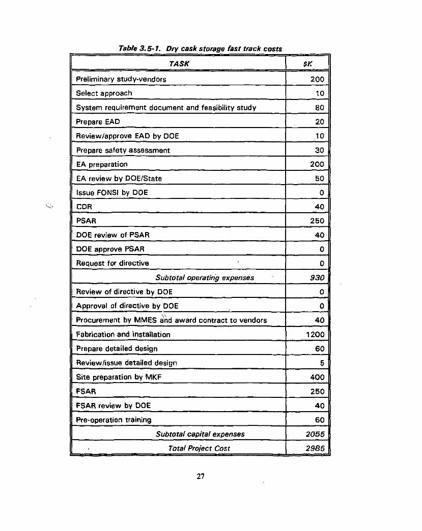
Table 3.5-1. Dry cask storage fast track costs
TASK $K
Preliminary study-vendors 200
Select approach 10
System requirement document and feasibility study 80
Prepare EAD 20
Review/approve EAD by DOE 10
Prepare safety assessment 30
EA preparation 200
EA review by DOE/State 50
Issue FONSI by DOE 0
CDR 40
PSAR 250
DOE review of PSAR 4 0
DOE approve PSAR 0
Request for directive 0
Subtotal operating expenses 930
Review of directive by DOE 0
Approval of directive by DOE 0 v>.
Procurement by MMES and award contract to vendors 4 0
Fabrication and installation 1200
Prepare detailed design 60
Review/issue detailed design 5
Site preparation by MKF 400
FSAR 250
FSAR review by DOE 4 0
Pre-operation training 60
Subtotal capita1 expenses 2055
Total Project Cost 2985
27
An additional assumption is that the casks can be procured as a turn-key job direct from a
qualified vendor.
A final assumption is that existing RRD QA is adequate for this activity. If not, additional cost
and schedule impacts can be expected.
28
4. ORNL Pool Storage Alternative
Information regarding on-site pool storage options for HFIR spent fuel has been gathered from
staff knowledgeable about reactor pools at the ORNL site. None of the specifics such as pool
dimensions and contents have been verified. The reactor pools identified for consideration are
the Oak Ridge Research Reactor (ORR) pools, the Bulk Shielding Reactor (BSR) pool, the
Tower Shielding Reactor (TSR) pool, the Radiochemical Engineering Development Center
(REDC) californium pool, and the High Flux Isotope Reactor (HFIR) pools. The HFIR pools
were not investigated as a part of this study; however information provided under Task 2 of the
Program Plain for Managing Spent Fuel at ORNL covering HFIR pool storage has been
incorporated into this document to provide a complete picture of the short-term spent fuel
storage options.
One concern is common to all pool storage options: The HFIR spent fuel elements are corroding
while being stored in the HFIR pool. As long as the spent fuel elements continue to be stored in
water, this corrosion will continue. Eventually, the spent fuel elements are likely to begin to leak
radioactive material into the storage pool, though no one knows for certain how long this will
take. Possible mechanisms for inhibiting corrosion have been discussed, but no solutions have
been arrived at. One suggestion has been to seal the spent fuel elements in cans backfilled with
an inert atmosphere, then return the canned fuel elements to a pool. In order to avoid having to
recan the fuel elements at some future time, some knowledge of the planned disposition of the
fuel is needed prior to designing a can and canning process.
4.1 Description of ORNL Reactor Storage Pools
4.1.1 ORR Pools
The ORR facility is scheduled to be turned over to DOE/EM for decontamination and
decommissioning (D & D) on October 31,1992 which means that a great deal of resistance to
using the ORR facility for spent fuel storage can be expected. DOE/OR has already stated that
29
the ORR shut down of operations is permanent, and office space is being put into the facility.
To reopen the facility for spent fuel storage would be extremely difficult, if not impossible. It
might require that RRD pay significant facility closing costs.
The ORR has two reactor pools, referred to as the west pool and the center pool. According to
the former facility manager, Gary Coleman, who has recently retired, the west pool is full of
radioactive hardware being transferred with the facility and would have no room for spent fuel.
The center pool, which is 10 feet wide, 15-20 feet long, and 27 feet deep, contains some hardware
but would have room for some fuel. Mr. Coleman thought that it would be necessary to
piggyback the fuel to fit a significant number of fuel elements into the pool. He was concerned
about the floor load limits for the facility, and said that an architectural study would be needed to
determine how much fuel could actually be placed into the pool.
A 20-ton crane is present in the facility. This would be large enough to carry the old HFIR spent
fuel transport cask (23,000 lb gross weight) or either of the new transport casks being pursued for
offsite transport. However the floor load limit is reportedly too low to permit any of these casks
to be set on the facility floor, so a means for transferring fuel into the facility without exceeding
the floor load limit would have to be developed. The GE-600 cask (23,300 lb gross weight) has
reportedly been used at the ORR, so using a cask of this weight should be possible.
To place the HFIR fuel in the pool, an accident analysis would have to be performed. If an
accident could be postulated in which water was lost from the pool, so that shielding of the HFIR
spent fuel elements would be lost, a significant amount of design modification to the facility might
be required before the HFIR spent fuel could be placed in the pool. Based on available
information, loss of pool water is a likely accident scenario. Modification of the facility to ensure
water containment in the event of an accident is expected to be a prohibitively expensive
proposition.
The pool does have water chemistry control. The adequacy of this for HFIR spent fuel storage
would need to be determined.
30
4.1.2 BSR Pool
The BSR pool is approximately 40 feet long, 60 feet wide, and 27 feet deep. Quite a bit of material is now scattered about the pool/ An architectural study would be needed to determine how much HFIR spent fuel could physically be placed in the pool.
According to Gary Coleman, the former facility manager who has recently retired, the BSR pool
is currently scheduled to be turned over to DOE/EM in about three years. Being able to do this
is contingent on being able to move the BSR fuel now stored there to SRS. Two things may
interfere with movement of BSR fuel to SRS; both are problems shared by the HFIR spent fuel
management effort: (1) SRS may no longer be able to accept this fuel because of the possibility
that SRS fuel reprocessing may be discontinued, or (2) a shipping cask may not be available to 1.1
transport the BSR fuel to SRS. (No shipping cask is available at this time which is certified to
transport the BSR fuel.) As long as the BSR fuel cannot be removed from the pool, the BSR
pool cannot be decommissioned. As long as it cannot be decommissioned, the HFIR spent fuel
could also be stored there, assuming other problems related to use of the BSR pool were
overcome. Once the BSR fuel was removed from the pool, RRD would have to be willing to pay
maintenance costs for the facility, and possibly facility shut-down costs as well, in order to
continue to store HFIR fuel there. These costs were estimated at $700K per year for
maintenance and surveillance, and $700K for shut-down.
One limitation of the BSR pool is that it has only a 7V2-ton crane. This would hot support the old
HFIR spent fuel transport cask (23,000 lb gross weight) or either of the new transport casks being
pursued for offsite transport. Either a larger-capacity crane would have to be added to the
facility, or another means for transferring HFIR spent fuel into and out of the facility would have
to be developed. Transferring the fuel via the ORR pool was suggested but the feasibility of this
has not been determined.
As with the ORR pool, the floor load limit for the BSR pool is reportedly too low to permit a
shipping cask to be set on the facility floor. Therefore a means for transferring fuel into the
facility without exceeding the floor load limit would have to be developed if this pool were to be
used.
31
Also in common with the ORR pool, an accident analysis would have to be performed before
HFIR spent fuel could be placed in the pool. If an accident could be postulated in which water
was lost from the pool, so that shielding of the HFIR spent fuel elements would be lost, a
significant amount of design modification to the facility might be required before the HFIR spent
fuel could be placed in the pool. Based on available information, loss of pool water has already
been postulated for this facility in an accident scenario. Modification of the facility to ensure
water containment in the event of an accident is expected to be a prohibitively expensive
proposition.
The pool does have water chemistry control. The adequacy of this for HFIR spent fuel storage
needs to be determined.
4.1.3 TSR Pool
According to Leo Holland, the facility manager, the TSR has only an outdoor maintenance pool, now empty except for water and algae. The main part of the pool is 20 feet long, 20 feet wide,
/ t
and 25 feet deep. The pool also has a neck 11 feet long, 4 feet wide, and 22 feet deep. A half
wall separates the bottom part of the main pool from the neck. Three two-foot-thick reinforced
concrete slabs cover the pool when it is not in use. These slabs would have to be removed to
gain access to the pool. Most cranes are not large enough to lift the slabs, but the slabs could
probably be lifted using the tower hoist. <
The TSF was placed in standby on September 30 of this year and DOE direction to prepare the
facility for shutdown is expected in the near future. At this time, the only existing TSR fuel
assembly is being stored in the reactor core rather than in the pool. DOE has indicated that they
may want the TSF spent fuel out of the reactor core, so it may soon be necessary to place the
fuel in the TSF pool. The TSF spent fuel assembly consists of 21 fuel elements and 4 fuel plates;
the facility manager did not know how much of the pool space would be required to store these
materials. No shipping cask is available to move the TSF fuel offsite, so few storage alternatives
are available for the TSF spent fuel assembly.
32
Water chemistry has not been controlled at the pool — the pool was filled with potable water some time ago and has been left undisturbed since. The pool has had a pumping system, but reportedly does not have good pH control, nor is it set up for water demineralization. Thus higher corrosion rates would be postulated for spent fuel stored in this pool than for spent fuel stored in a pool where the water chemistry can be carefully controlled.
As with the other pools, an accident analysis would have to be performed. If an accident involving loss of pool water could be postulated, the TSR pool would be a poor choice for HFIR spent fuel storage without significant, possibly prohibitively expensive, modification.
4.1.4 REDC Californium Pool
According to E/;iory Coliins, head of the Chemical Technology Division's Isotope Technology Section, the REDC caSifornium pool is 21) feet long, 9Vt feet wide, and 22 feet deep minimum. A canal in the middle of the pool is ? fee? Jong, runs the entire 91/2-foot width of the pool, and extends to an additional 12 feet of depih for a total depth of 34 feet. This canal is located under the californium --loading station, so is inaccessible in any case. The californium loading station itself is 12 feet lonjg and runs, two-thirds the width of the pool. Californium sources are stored in the loading station.
A major drawback of this pool is its limited space availability. The large size of the loading station leaves little room for HFIR spent fuel storage. Only one to two HFIR spent fuel storage racks could be placed in the space adjacent to the loading station. Piggybacking the fuel might increase storage capacity somewhat.
Another concern is that, unlike the other pools considered so far which are essentially inactive,
this pool is a regular part of californium operations. Great care would be required to ensure that
any spent fuel stored in this pool would not contaminate the pool (for example, via the corrosion
process) or in any other way jeopardize the californium operations.
Because of the presence of californium, a strong neutron emitter, operational controls would have
to be established to ensure that the HFIR spent fuel remained neutronically isolated at all times
33
from the californium. As long as the water remained in the pool this would not be a severe ,
operational constraint, because only 1 foot of water is needed to provide the necessary
isolation. However if an accident involving loss of water from the pool could be posti.. J. ; :ore
severe operational restrictions or significant pool modifications might be required. Thr: . 's::v J analysis and documentation requirements for this option are probably substantial.
r P
The REDC does have a 50-ton crane which should be able to access the pool area, so that
loading and unloading with existing transport casks should be possible. This needs to be verified. i1
The pool does have good water chemistry control.
4.1.5 HFIR Pools
Expansion of existing HFIR pool storage capabilities is being evaluated as a separate activity, not as a part of this task. However the information generated by that activity is necessary to any HFIR spent fuel management decision, so a discussion of the HFIR expanded pool storage option is included here.
HFIR has four pools: the reactor pool, the west (or center) pool, the east pool, and the critical
pool. The reactor pool cannot be used for storage of HFIR spent fuel elements because of the
reactor operations which take place in this pool. The pool must sometimes be partially drained,
which would create operating concerns as well as ALARA concerns for reactor operators working
in the area.
The west pool currently contains a 4 x 3 x 1 storage array as well as two storage positions needed
for loading and unloading operations. The rest of the pool is taken up with a cask loading pad,
experiment storage racks, and plate racks. Expansion of storage in this pool is not considered
viable because it would interfere with pool operations. The pool does have adequate water
chemistry control.
The east pool is now approved for a 6 x 8 x 1 array. However to attain this full array size it will
be necessary to remove several large items of contaminated materials and equipment from the
3 4
pool. Discussions are underway with ORNL Waste Management staff to determine what can be
done to remove these materials from the pool. If a means for removing these materials from the
east pool is not developed, expansion of east pool storage to a 6 x 8 x 1 array will not be possible.
This would have the effect of decreasing the time available to identify and implement a storage
alternative for the HFIR spent fuel.
The east pool is the focus of existing efforts to expand HFIR spent fuel storage capabilities. Two
options are being investigated. One involves close-packing the HFIR spent fuel elements to
increase storage capacity without stacking. The other involves stacking the spent fuel elements
two or three layere deep. If all the contaminated materials and equipment could be removed
from the pool, an array as large as 6 x 8 x 3 may be possible using the piggybacking alternative.
This would provide an additional 96 storage spaces, potentially providing an additional 8 years of
HFIR operation if corrosion issues could be overcome. The east pool also has good water
chemistry control.
The critical pool is a 10-foot-diameter pool Filled with contaminated materials and equipment and
slimy water. Although water chemistry control is supposed to be available for the pool, it has not
been used. Emptying the pool of the materials stored there and decontaminating the pool is
believed to be very expensive. However it may be important to attempt these activities to
increase spent fuel storage capacity. It has been estimated that a "six-shooter" array could be
placed in the pool, possibly stacked three deep. This would provide an additional 18 storage
spaces, potentially keeping HFIR in operation for an additional IVi years. Regardless of whether
or not the pool is to be used for spent fuel storage, ORNL Waste Management staff have urged
HFIR management to act quickly to remove the material from this pool and find appropriate
means to dispose of or retrievably store these materials, because disposal and storage options for
these materials are rapidly diminishing as Solid Waste Storage Areas at ORNL continue to close.
35

4.2 Regulatory and Other Requirements
4.2.1 Safeguards and Security Requirements
At this time, the ORR and BSR are grouped into the same material accountability area for
safeguards and security. The material accountability area is listed as a Category III facility. No
special nuclear material (SNM) is now present within the ORR. However the BSR does have an
amount of SNM (approximately 4 kg of attractiveness level D and 10 kg of attractiveness level E)
that would severely restrict the amount of HFIR spent fuel which could be placed in the facility.
To get around this limitation for the ORR, it would be necessary to separate the facility into a
different accountability area. This is fairly straightforward to do, requiring primarily appointment
of a custodian and an alternate. However for the BSR pool, the presence of 14 kg of
attractiveness level D and E material in the pool restricts the amount of additional SNM allowed
in the facility to 36 kg. This equates to roughly 5 HFIR spent fuel elements. To exceed the 50
kg total SNM limit would require upgrading the BSR to a higher security category, which would
be an expensive undertaking as discussed in Section 2.1 of this report. Because the attractiveness
level of the BSR fuel will increase over time as the radiation level emitted from the fuel
decreases, the amount of additional SNM permitted in the pool may be further restricted to
ensure that the 50 kg SNM limit will not be exceeded over the expected storage time of the SNM
in the BSR pool.
The TSF is not limited by safeguards and security requirements at this time. Most of the material
present there is attractiveness level E, which can be stored in unlimited quantity in a Category IV
facility.
Building 7930 does not now contain any SNM. Therefore an unlimited amount of HFIR spent
fuel could also be placed in the REDC Californium pool without impacting existing safeguards
and security requirements. However the placement of this material into the facility would have
the effect in the future of restricting placement of higher attractiveness levels of SNM to less than
1000 grams without upgrading the safeguards and security classification for the facility. It is not
known whether this would pose a significant impediment to future operations at the facility.
36
The HFIR stores primarily attractiveness level E materials. Unlimited amounts of HFIR spent
fuel could be stored at this facility without having to upgrade the facility beyond Category IV.
4.2.2 NEPA Requirements
NEPA requirements are summarized in Section 2.2 of this report. These requirements are
expected to have significant impacts on HFIR spent fuel management alternatives.
As mentioned in Section 2.2, it is hoped that increasing storage capacity in the HFIR pools could
be covered by a Categorical Exclusion (CX), since similar activities are already taking place at
HFIR. However an application needs to be made to DOE to obtain concurrence with this
approach.
To place the HFIR spent fuel into any non-HFIR pool is expected to require significant NEPA
documentation, probably an E A Preparation, submittal, and response for an ADM, as explained
in Section 2.2, could take 6 months or more. Preparation, review, and approval of the EA could
then take two years or more. In all this time, design work could not proceed on the project. A
great many ORNL projects are reportedly on hold due to the long times required to obtain
approved NEPA documentation. Due to the critically short time in which a storage alternative
must be put in place, the NEPA documentation requirements make HFIR pool storage look very
favorable compared to other pool storage alternatives, assuming a CX could be obtained for the
HFIR pool storage expansion.
4.2.3 RCRA Requirements
Assuming the conditions stated in Section 2.3 of this report can be met, RCRA regulations would
not apply to any of the pool storage options.
4.2.4 Transportation Requirements
All of the pools under consideration are on the ORNL reservation and may be reached without
any offsite transport. Therefore a certified shipping container would not be required for the
37
movements, as discussed in Section 2.4. However, as noted earlier in this section in individual
discussions on each of the pools, issues such as facility crane limitations or floor loading
constraints would need to be addressed for the non-HFIR pools. A means by which the HFIR
spent fuel could be unloaded and placed into the various facilities would require further
investigation.
4.2.5 Safety Documentation Requirements
In terms of safety documentation requirements, as explained in Section 2.5 of this report, HFIR
pool storage is at a tremendous advantage over storage in any of the other pools. HFTR has a
newly revised SAR written to current requirements which is to be submitted to DOE by the end
of October 1992. Therefore the primary safety documentation requirement for HFIR pool
storage would be an SA, including a USQD, followed by modification of the existing SAR to
incorporate any necessary changes. RRD has experience in processing this type of documentation
in a matter of months.
To place the HFIR spent fuel into any of the other ORNL pools, an SA would have to be
followed by a SAR written for the entire facility and approved by DOE/HQ. Because SARs
written to current requirements do not now exist for these facilities, the SAR development effort
could take several years and several million dollars. Upgrading these facilities to contain a
moderate hazard material could also require significant, possibly prohibitively expensive, physical
improvements to the facilities. Due to the lack of reliable design information, it may not be
possible to prepare an acceptable SAR for these facilities to store the HFIR spent fuel.
4.2.6 Nuclear Criticality Safety Requirements
As explained in Section 2.6, DOE's nuclear criticality safety requirements are in a state of flux. It
is believed that these requirements will be incorporated into new SAR documentation
requirements in the near future. A nuclear criticality review will be required for any of the pool
storage options.
38
4.3 Feasibility of ORNL Pool Storage as Short-Term Alternative
HFIR pool storage is the only pool storage option that may be feasible as a short-term
alternative. NEPA and safety documentation requirements, as well as the need to rectify physical
inadequacies in the other facilities, all contribute to make other ORNL pool storage options
unachievable in the short term.
For HFIR pool storage to be achievable in the short term, a very fast-track program would have
to be implemented. This fast-track program is feasible only if the project is subject to Categorical
Exclusion (CX) so that an EA or EIS is not required, capital funds are immediately available,
existing radioactive waste in the pool can successfully be turned over to the Waste Management
and Remedial Action (WMRA) Division, existing RRD Quality Assurance (QA) requirements
can be used, and both ORNL and DOE can process necessary documents in extremely short
times. Failure in any one of these areas would jeopardize continued HFIR operation. Section
4.4 lays out cost and schedule estimates for achieving HFIR pool storage expansion in the short
term.
4.4 Cost and Schedule Estimates
Figure 4.4-1 presents a fast-track schedule for expanding HFIR pool storage. Table 4.4-1 presents
associated costs. As mentioned in the previous section, several impediments to this schedule
might arise. First, this schedule assumes that expanding spent fuel storage in the HFIR pool will
be subject only to a CX, so that further NEPA documentation will not be required. A
requirement to provide either an EA or an EIS would make HFIR pool expansion impossible to
achieve in the short term. The schedule also assumes that DOE/NE will process the application
for a CX in only 2 months, an extremely short — though not unheard of — time. A slippage of
more than two months in the CX response would unacceptably delay this schedule and jeopardize
continued HFIR operation.
Another assumption is that existing capital funds, specifically Accelerator Reactor Improvement
and Modification (ARIM) funds, would be diverted to fund this activity. If the activity became a
39
As-of Date : 10/20/92 Schedule File : GREEN4
Task Name
Preliminary Study-RRD System Requirement Docunent Feasibility Study Criticality Analysis Prepare CX Review/Approve CX by DOE Prepare Safety Assessment Conceptual Design Request for Directive Review of Directive by DOE APPROVAL OF DIRECTIVE BY DOE Detailed Design Draft SAR Modification SAR Nod Approval by DOE Prequalification of Vendors Procurement by MMES AUARD VENDOR CONTRACTS Fabrication Installation OPERATION
93 Start End Jan Date Date 4
10/1/92 11/2/92 • . 11/2/92 5/3/93 12/1/92 6/1/93 11/2/92 1/4/93 • l 12/1/92 2/1/93 2/1/93 3/31/93 4/1/93 6/1/93 6/1/93 7/30/93 7/30/93 8/2/93 8/2/93 9/30/93 9/30/93 9/30/93 9/30/93 3/31/94 2/1/94 5/31/94 5/31/94 9/30/94 9/30/93 3/31/94 3/31/94 8/1/94 8/1/94 8/1/94 8/1/94 5/1/95 11/30/94 6/30/95 1/31/95 1/31/95
94
3
95
3
• • • Detail Task wmmm Surinary Task Baseline • (Progress) ==«• (Progress) ••• Conflict
(Slack) • • — (Slack) Resource delay Progress shows Percent Achieved on Actual a Milestone
Scale: 4 weeks per character
TIME LINE Gantt Chart Report, Strip 1
Fig. 4.4-1. Fast-track schedule for expanding HFIR pool storage.
Table. 4.4-1. HFIR poo/ expansion fast track costs.
TASK $K
Preliminary study-RRD 10
System requirement document and feasibility study 120
Criticality analysis 60
Prepare CX 6
Review/approve CX by DOE 0
Prepare safety assessment 20
Conceptual design V\ 40
Request for directive/ 0
Total operating expenses 256
Review of directive by DOE 0
Approval of directive by DOE 0
Detailed design 300
Draft SAR modification 150
SAR modification approval by DOE 20
Prequalification of vendors 30
Procurement by MMES and award vendor contracts 30
Fabrication 1200
Installation 60
Subtotal capital expenses 1790
Total Project Cost 2046
41
line item project, it could not be completed in less than seven years, and would more likely take
eight to ten years to achieve.
An additional assumption is that the existing RRD QA program would be adequate to cover this
activity. Significant additional costs and delays in schedule could accrue if a significant QA effort
•were required.
The schedule does not address removal of radioactive debris from the HFIR pool. It simply
assumes that the debris will have been removed from the pool before it could impact this activity.
An inability to remove the debris from the pool in a timely manner would jeopardize the HFIR
pool storage expansion effort.
Any delay in this schedule, by even a month, jeopardizes continued operation of HFIR.
Continued operation of HFIR is also dependent on being able to rerack and perform other
necessary operations (such as canning of the fuel elements) in a pool that is essentially full. As
all of this points out, HFIR pool expansion may be feasible in the short term, but this is by no
means certain.
42
5. Hot Cell Storage Alternative
It may be possible to provide for dry storage of spent fuel in existing ORNL facilities. A number
of build :ngs containing hot cells on the ORNL site were studied. These hot cells are typically
rather old (most having been built prior to the mid 1960s), and were not built for storage of
multiple HFIR spent fuel assemblies. However, several hot cells are not currently being used and
might provide space for temporary storage.
5.1 Description of Hot Cell Investigation
Nearly every building containing hot cells was examined to determine its suitability for temporarily
storing HFIR spent fuel assemblies. The sources of information included knowledgeable facility
personnel as well as the applicable Hot Cell Reference Guides compiled recently by H&R
Technical Associates, Inc. of Oak Ridge for each building.
A summary of the hot cells examined and the information obtained for each building is given in
Table 5.1-1. A number of parameters were studied for each hot cell, including whether the hot
cell was available, what general condition it was in, how much shielding it had, what size it was,
and what was the size of the access port to the cell. In addition, the crane capacity was
determined. It is expected that the old HFIR shipping cask would be used to move the spent fuel
from HFIR to a hot cell. This cask, loaded with a complete HFIR core has a gross weight of
23,000 lbs. Therefore a crane capacity of at least 12 tons will be required in the hot cell facility.
The final column in Table 5.1-1 shows whether the hot cell building should be considered further.
If the answer is no, the reason or reasons are then given. As can be seen in the table, only two
buildings are identified as being reasonable to consider further. The two buildings are 3019A and
7930.
43
Table S. 1-1. ORNL hot call summary Information.
Hot call building
Hazard rating
Calls available? General condition
Crane capacity
m Sin access
(ft! Cell size
fftl SMefding Consider further?
2 0 2 6 Low Yes. 1-6 High contamination levels 5 - 1 x 1 6 x 7 x 1 1 4 ' high density concrete
No -Contamination
3019A Moderate Yes - #1 & #2 Empty - Others being used for standby processing equipment and for U-233 and Pu storage
10 9 x 9 #1: 10 x 20 x 27 #2: 20 x 20 x 27
4 ' reinforced concrete Ire)
Yes -Crane capacity & NEPA will be
issues
3025E Generally accepted
No No - Cells unavailable
3 0 2 6 D Generally accepted
Yes Dirty Old equipment
50 0.5 roof Tunnel access or horizontal
A: 25 x 10 x 1*5 C: 21 x 9 x 10
Probably need to replace ZnBr windows 5 ' reinforced concrete
No -contamination
3 0 2 8 Generally accepted
Yes #5 & #7 Heavy contamination 5: 4 x 3 . 7 5 7: 0.6 diam
5: 6 x 9 x 12.5 7: 1 5 x 5 x 8 '
5: 9" steel, 1' concrete 7: 1-3'high density concrete
No -Contamination,
shielding, access
3 0 2 9 Generally accepted
Cells 1-3 are questionable
FP contamination 1 1 x 1 1: 5 x 8 x 1 3 2: 6 x 6 x 8 ' 3: 6 x 8 x 12
3' SS lined be No - cells too small, access
304-2 Generally accepted
2 just cleaned out
Still "hot" - About to go into Surplus Facility Program. Could load wet thru pool into 1 cell
20 1.2 N: 8 x 5 x 9.7 S: 8 x 6 x 9.7
3 .5 ' barytes concrete (be)
No - entering SFP
3047 Generally accepted
Yes - C&D Going into Surplus Facility Program
1 T i n cell
Roof plug C: 8 x 8 x 13 D: 8 x 6 x 13
C: 2 .25 ' be, 0 .75 ' steel D: 3 ' SS lined be
No - entering SFP
Table 5.1-1. ORNL hot cell summaiy information (cont). :
Hot ca/f building
Hazard rating
Calls available? General contamination
Crana capacity
m Ska access
(ft) Cell sUa
(ft) Shielding Consider further?
3505 Generally accepted
Yes Hasn't been operated since 1960. No secondary containment. Heavy contamination
Outside crane
Roof hatch 8 x 9 x 17 Ityp. of 7)
8" concrete No - shielding contamination
3517 Low 23 total cells Yessr
No: 2 Questionable: 21
Some cells heavily contaminated
20 Roof access Large hatches
9 x 12.5 x 12 (typ. of 5) 7.5 x 12.5 x 12 (typ. of 4)
1-3' concrete No -Contamination,
shielding
3525 Low No - Access for HFIR ass'y to only 1 cell and it is needed for rest of operations
Limited to 420g irradiated U-235; 2 0 0 , 0 0 0 Ci
10 No - cells unavailable
4501 Low Cell C is questionable
Unused since 1970s 3 x 3 8 x 6 x 15 3' SS lined be No - cell too small
4507 Generally accepted
Yes - 4 cells Heavy contamination -fission products & TRU. Shutdown since 1980
10 4' x 6' roof plugs
each: 6 x 1 0 x 11
4' be No • contamination
7920 No No - Cells unavailable
7930 Low Maybe -expect material from SRS
Never used - Need shielding for windows
5 0 bldg. 5 T i n
cell
Probably OK D: 41 x 20 x 24 E: 16 x 20 x 30
5.5 ' rc for 11'; 4 .5 ' rc for rest of height
Y e s -NEPA will be an;
issue
The ventilation systems in any hot cell facility will be an issue. Since the surface temperature of
the fuel assemblies must be kept below 400 °F, an active cooling system will be required. This
will likely mean that the HVAC system will become a safety system, and these hot cell HVAC
systems most likely do not meet safety system requirements.
For 3019A, the crane capacity is an issue, since the existing crane is limited to 10 tons. It may be
possible to put in a larger crane above cells 1 and 2 within the penthouse. Or it may be possible
to cut through the penthouse roof and use an outside crane. This was done to move equipment
into cell 3 for the Consolidated Edison Uranium Solidification Program (CEUSP) project.
Besides the crane capacity issue, the building has the disadvantage of being extremely old. It was
built in 1943 to process the irradiated uranium from the original graphite reactor. Because of its
older design, handling of the spent fuel within the cells would be difficult and would restrict the
number of assemblies which could be stored.
A disadvantage of Building 7930 is that the 7930 cells are probably the best that currently exist at
ORNL (and quite possibly in the country). They are continuously proposed as being suitable for
doing new work. The latest proposal envisions using the hot cells for a special waste handling
demonstration project. If they are used for storing HFIR spent fuel, they would be unavailable
for new uses. Advantages of the use of 7930 include: the proximity of the hot cells to the HFIR,
making transfer of the spent fuel simpler since all operations can be kept within the 7900 area;
the cleanliness of the cells, since cells D and E have essentially been unused; and the large size of
the cells, making storage of a significant number of spent fuel assemblies feasible. A further
advantage of cell E is that it was originally designed to accommodate high heat removal
requirements. A final advantage of Building 7930 is that the access between cells D and E means
that a transfer cask could be loaded into cell D, the spent fuel assembly could be unloaded and
transferred to cell E, and the transfer cask could then be removed. This arrangement allows for
very low personnel exposures.
* % L•
46
5.2 Regulatory and Other Requirements
5.2.1 Safeguards and Security Requirements
As described in Section 2.1, Building 3019A is already a Category I facility. Therefore an
unlimited amount of HFIR spent fuel could be stored at the facility without any impact to
safeguards and security requirements for the building.
Building 7930 does not contain any SNM at this time. Therefore an unlimited amount of HFIR
spent fuel could be placed in this facility without impacting existing safeguards and security
requirements. However placement of this material into the facility would have the effect in the
future of restricting placement of higher attractiveness levels of SNM to less than 1000 grams
without upgrading the safeguards and security classification for the facility. It is not known
whether this would pose a significant impediment to future operations at the facility.
5.2.2 NEPA Requirements
NEPA requirements are summarized in Section 2.2 of this report. These requirements are
expected to have significant impacts on HFIR spent fuel management alternatives.
To place the HFIR spent fuel into an ORNL hot cell is expected to require significant NEPA
documentation, probably an EA. Preparation, submittal, and response for an ADM, as explained
in Section 2.2, could take 6 months or more. Preparation, review, and approval of the EA could
then take two years or more. In all this time, design work could not proceed on the project. A
great many ORNL projects are reportedly on hold due to the long times required to obtain
approved NEPA documentation. Due to the critically short time in which a storage alternative
must be put in place, the NEPA documentation requirements make hot cell storage look
unfavorable as a short-term management alternative.
47
5.2.3 RCRA Requirements
Assuming the conditions stated in Section 2.3 of this report can be met, RCRA regulations would
not apply to any of the hot cell storage options.
5.2.4 Transportation Requirements
Both of the hot cells under consideration are on the ORNL reservation and may be reached
without any offsite transport. Therefore a certified shipping container would not be required for
the movements, as discussed in Section 2.4. However, as noted in Section 5.1, issues such as
facility crane or access limitations would need to be addressed for the hot cells as part of the
design activities, so that a means for unloading the HFTR spent fuel and placing it into the hot
cells could be developed.
5.2.5 Safety Documentation Requirements
In terms of safety documentation requirements, as explained in Section 2.5 of this report,
placement of the HFIR spent fuel into one or more of the available hot cells would require
significant safety documentation. First an SA would have to be written, including a hazard
screening and a USQD, This would have to be followed by a SAR written for the entire facility,
including the HFIR spent fuel storage in its scope. For a moderate hazard classification, which
this is likely to be, approval by DOE/HQ is now required.
Because SARs written to current requirements do not now exist for these facilities, the SAR
development effort could take several years and several million dollars. Upgrading these facilities
to current requirements for handling of moderate hazard materials could also require significant,
possibly prohibitively expensive, physical improvements to the facilities. The Energy Systems
Safety Analysis Report Update Program (SARUP) provided an estimate of 5 years and $3M to
write a SAR for Building 3019A. This cost estimate did not include any physical improvements
which might be required for the facility. Building 7930 has better documentation available so the
SAR should be somewhat less time-consuming and expensive to produce, but would still likely be
48
on the order of 2 to 3 years and $2M, not including physical improvements that might be
required.
5.2.6 Nuclear Criticality Safety Requirements
As explained in Section 2.6, the nuclear criticality safety requirements are in a state of flux. It is
believed that these requirements will be incorporated into SAR documentation requirements in
the near future. A nuclear criticality review will be required for any of the hot cell storage
options.
5.3 Feasibility of Hot Cell Storage as Short-Term Alternative
ORNL hot cell storage does not appear feasible as a short-term alternative. The long times
required first for NEPA documentation, then for safety documentation, make it impossible to
implement a hot cell storage alternative before the HFIR pool is full. Significant facility
modification is also expected to be required for any of the hot cell options investigated. In
addition, the option is very expensive, making it likely that it would have to be implemented as a
line item project. That in itself would require a minimum of 7 years, but more likely 8 to 10
years, to implement.
As an intermediate-term alternative, this option may be achievable. A great deal would depend
upon the safety evaluations performed as part of the SAR upgrade activities, and the facility
upgrades which would be required to allow these facilities to store moderate hazard materials
safely.
Of the hot cells available, only cells D and E in Building 7930 appear to warrant further study.
They are preferred over those in Building 3019A primarily because obtaining an approved SAR
for 3019A, which is over 45 years old, is likely to take several years and a great deal of funding,
without any certainty of success. Principal problems in producing an acceptable SAR include lack
of as-built dr awings, lack of complete information about facility contents, and lack of engineering
design data and analysis for the facility. Preparation and approval of a SAR for 7930 should be
less expensive and time-consuming, with a greater probability of success.
49
From a longer term standpoint, the use of a hot cell would not appear to be as desirable as the
use of dedicated spent fuel dry cask storage. The number of spent fuel assemblies which could be
stored in the hot cells is limited by a physical size limitation, irradiation damage to the walls, and
by limited shielding, and possibly by ventilation constraints. Some of these limitations could be
designed around, but the expense involved is expected to be significant. Further, the 7930 hot
cells are excellent candidates for new programs. Their use for long-term storage would make
them unavailable for use by new programs.
5.4 Cost and Schedule Estimates
/ y Figure 5.4-1 presents a fast-track schedule for providing ORNL hot cell storage. This schedule
shows the first transfer of spent fuel to occur in July 1997. Table 5.4-1 presents associated costs.
Even on a fast-track schedule, this option is not achievable in the short term. In the intermediate
term, this option does not look favorable compared to design of a new dry cask storage facility.
This is primarily because a dry cask storage facility should be achievable in a shorter time and
with a greater probability of success.
The fast-track schedule makes several assumptions. If any of these assumptions cannot be
implemented, the schedule will be delayed accordingly. First, the schedule assumes that an EA
can be written in 3 months and approved by DOE and the state in 6 months. This short a review
schedule has never been achieved. Typically two or more years are reportedly required to obtain
DOE and state approval.
Similarly optimistic estimates have been made for safety documentation activities. A 20-month
time span is allotted for preparation, review and approval of a SAR. Such a short total cycle time
for a major SAR is extremely aggressive and optimistic. For Building 7930, which is the more
achievable of the hot cell alternatives, two or more years to prepare the SAR is thought to be
more realistic.
This schedule also assumes that minimal building modification will be required. It assumes, for
instance, that adequate ventilation already exists in the hot cell(s) to be used, and that shadow
shielding will be adequate.
50
As-of Date : 10/20/92 Schedule File : GREEN3
Start End Tusk Home Date Date
Preliminary Study-RRD 10/1/92 11/2/92 System Requirement Docunent 11/2/92 1/4/93 Feasibility Study 1/4/93 6/30/93 EAD Preparation 1/4/93 3/31/93 EAD Approval by DOE 4/1/93 6/30/93 Safety Assessment Preparation 4/30/93 6/30/93 EA Preparation 7/1/93 9/30/93 EA Review/Approval-DOE/STATE 9/30/93 3/30/94 FONSI 3/30/94 3/30/94 CDR Preparation 3/30/94 9/30/94 PSAR Preparation 9/30/93 9/30/94 PSAR Approval by DOE 9/30/94 3/30/95 Request for Directive 3/30/95 3/31/95 Review of Directive by DOE 3/31/95 6/1/95 APPROVAL OF DIRECTIVE BY DOE 6/1/95 6/1/95 Detailed Design 6/1/95 1/31/96 Prepare FSAR 6/1/95 6/3/96 Review FSAR by 00E 6/3/96 2/3/97 APPROVAL OF FSAR BY DOE 2/3/97 2/3/97 Prequalify Vendors 8/1/95 1/31/96 Procurement by MMES 1/2/96 4/30/96 AWARD CONTRACT TO VENDORS 4/30/96 4/30/96 Purchase of Equipment 4/30/96 1/30/97 InstalIat ion 12/2/96 5/30/97 Operator Training/Testing 5/30/97 7/31/97 OPERATION 7/31/97 7/31/97
93 94 95 96 97 Jan 4 3 3 2 2
Detail Task «a«sa Sunmary Task Baseline • (Progress) ==«w (Progress) ••• Conflict • • — (Slack) «=»— (Slack) . Resource delay Progress shows Percent Achieved on Actual a Milestone
Scale: 4 weeks per character -
TIME LIME Gantt Chart Report, Strip 1 ~
Fig. 5.4-1. Fast-track schedule for hot cell storage.
Table 5.4-1. Hot cell storage fast track costs.
TASK $K
Preliminary study-RRD 10
System requirement document and feasibility study 250
EAD preparation 20
EAD approval by DOE 10
Safety assessment preparation 30
EA preparation 200
EA review/approval-DOE/STATE 50
FONSI 0
CDR preparation 100
PSAR preparation 400
PSAR approval by DOE 100
Request for directive 0
Review of directive by DOE 0
Approval of directive by DOE 0
Subtotal operating expenses 1,170
Detailed design 400
Prepare FSAR 800
Review FSAR by DOE 200
Approval of FSAR by DOE 0
Prequalify vendors 30
Procurement by MMES and award contract to vendors 30
Purchase of equipment 2000
Installation 200
Operator training/testing 60
Subtotal capital expenses 3,720
Total Project Cost 4 ,890
52
ft
Another assumption is that Accelerator Reactor Improvement and Modification (ARIM) funding
will be available to fund this activity. If this had to be funded as a line item project, a minimum
of 7 years, but more likely 8 to 10 years, would be required for this activity.
A final assumption is that existing RRD QA is adequate for this activity. If not, additional cost
and schedule impacts can be expected.
53
6. Oflsite Alternative
6.1 Description of Offsite Options
Up until 1985, ORNL shipped HFIR spent fuel assemblies to SRS for reprocessing. This was
halted when the old HFIR shipping cask was decertified. However, SRS continues to reserve
space for 20 HFIR assemblies in its RBOF (Receiving Basin for Off-site Fuels) facility. If ORNL
can find an approved shipping cask, it could presumably ship at least 20 assemblies to SRS.
Discussions are continuing within DOE as to the fate of the reprocessing facilities at SRS and
also the Idaho Chemical Processing Plant (ICPP). An initial decision has been made to
permanently shutdown the ICPP. At present, it is expected that the SRS reprocessing facility will
continue to operate through FY 1996, per a conversation with Bill Dennis, DOE/SR. SRS feels
this is required since to shutdown their canyons, they must reprocess liquid which is stored there.
They would like to coprocess materials from the RBOF during this period. If they are permitted
to do so, it may be possible to ship more than 20 HFIR spent fuel assemblies to the RBOF.
In order to ship assemblies to SRS, an approved shipping cask must be obtained. Efforts to
accomplish this are pursuing three paths: (1) design and approval of a new cask (called the GNSI
cask); (2) purchase of an existing commercial shipping cask from General Electric Corporation
(GE); and (3) purchase of special services to use the GE cask on an emergency basis. With any
option to obtain a cask from a vendor, it will also be necessary to obtain all ancillary equipment
to operate the cask. This includes items such as the lifting yoke (capable of mating with the hook
on the HFIR bridge crane), tiedowns, and special equipment for removing or inserting the
shielding insert. In addition, training will have to be supplied by the vendor to both ORNL and
SRS personnel on the operation of the cask.
At this time, the first path does not appear to be achievable in the short term. The process of
trying to obtain a DOE Certificate of Compliance (CoC) for the GNSI cask has been slow and
54
expensive. According to recent review comments from DOE, significant additional design
modification work is needed before this cask could be considered for approval.
The second path involves establishing a contract with GE to revise the NRC CoC for the GE-
2000 cask so that the cask is approved to transport HFIR fuel and to produce a GE-2000 cask
system that meets the revised CoC. A key subtask is to agree with GE on price and schedule of
the various tasks, including designing a new basket to hold one entire HFIR assembly in the
cavity, revising the criticality analysis to account for the increased fissile material loading of the
HFIR fuel, revising the original Safety Analysis Report for Packaging (SARP) and submitting it to
NRC, answering all NRC questions, obtaining the revised CoC, letting a subcontract with a
fabricator to build a new model of the GE-2000, assuring that the fabricator has the proper QA
program in place, providing inspectors during fabrication to assure fabrication is in accordance
with design, and maintaining a complete QA file to turn over to MMES with the completion of
the contract.
A fast track schedule for this path is shown in Table 6.1-1.
This path contains some risk. It has been assumed that approximately one year will be required
to build the cask once farication is initiated. Therefore fabrication is assumed to be started
before NRC approves the proposed modification to the CoC. The risk is considered small, since
the cask has already been approved by NRC and the modifications to the CoC that GE would
request are not considered controversial. Taking this risk would increase the likelihood that GE
would be able to deliver the new cask in early 1994.
The third path involves establishing an emergency provision contract with GE for services to
permit the existing GE-2000 cask to be used if a new cask is not available by the time of need
(February 1994). The provisions of this contract would be invoked for a limited time period, only
if the GE-2000 cask had an NRC-approved revised CoC authorizing HFIR spent fuel shipment,
and the new GE-2000 cask had not been fabricated in time to initiate shipping by February 1994.
However, under this scenario, GE might require the assembly to be canned in order to prevent
unwanted contamination of their cask by the HFIR spent fuel.
55
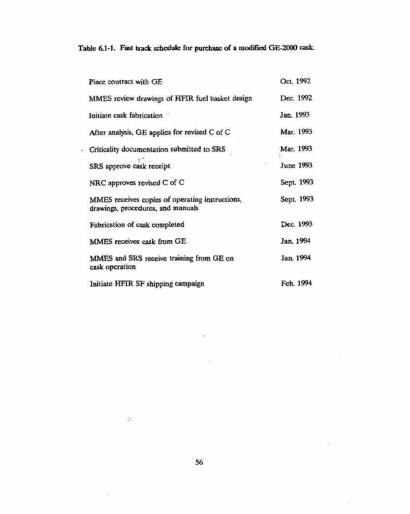
Table 6.1-1. Fast track schedule for purchase of a modified GE-2000 cask.
Place contract with GE Oct. 1992
MMES review drawings of HFIR fuel basket design Dec. 1992
Initiate cask fabrication Jan. 1993
After analysis, GE applies for revised C of C Mar. 1993
Criticality documentation submitted to SRS Mar. 1993
SRS approve cask receipt June 1993
NRC approves revised C of C Sept. 1993
MMES receives copies of operating instructions, Sept. 1993 drawings, procedures, and manuals
Fabrication of cask completed Dec. 1993
MMES receives cask from GE Jan. 1994
MMES and SRS receive training from GE on Jan. 1994 cask operation
Initiate HFIR SF shipping campaign Feb. 1994
56
In the emergency use (third) path, GE would have to carry out all activities required in the
second path, and in addition they would be asked to analyze their cask for transport of a sealed
canister containing the HFIR spent fuel. Normally, the canister would be used only if a HFIR
core were determined to be leaking Fission products, and to date, this has never happened to a
HFIR fuel element. However corrosion of the fuel elements resulting from long-term pool
storage makes leakage a possibility in the future. At GE's option, though, the canister might have
to be used whether or not any part of the core was found to be leaking. In the emergency use
scenario, MMES would be responsible for the canister design; they would also develop operating
procedures for encapsulating a HFIR core in the canister, purging the water from the canister,
and storing the canned element underwater until shipment. Since the canister would be designed
to fit inside the GE-2000 cask as assembled for shipping HFIR cores, this canister design would
have to be analyzed and the analysis included in the application to the NRC by GE to amend the
existing GE-2000 CoC. Because of the additional work required of MMES in designing a sealed
canister followed by the analysis required of GE assuming the canister was part of the shipping
package, as well as the need for review of this additional information by the NRC, the potential
for extending the time required to obtain the NRC CoC amendment is great, fj
If GE does not insist on canistering of the HFIR fuel in their cask, MMES may be better served
to eliminate the request that GE evaluate the use of the canister in the cask and follow path two;
this would decouple the option of shipping canistered fuel from the initial GE application to NRC
for a CoC amendment, and possibly reduce the time needed to obtain NRC approval. A request
for a later amendment to the NRC CoC to cover transport of canistered fuel could then be
pursued at a later date, if and when MMES chose to ship canistered fuel. However, there are
two reasons for designing and fabricating the canister early. The first, as noted above, is that GE
may insist on it if path three is followed. The second is that, at this time, HFIR has the capacity
to store only one leaking HFIR fuel assembly. (One leaking assembly could be stored on a
temporary basis in a failed fuel element storage container located in the reactor pool.)^rleaking
assembly would need to be canned in order to prevent extensive contamination of the HFIR
pools during storage and prior to shipping. Therefore, availability of an empty canister that is
designed to fit inside the GE-2000 cask may be a highly desirable "insurance policy," both to RRD
and to DOE, since it could provide a means to remove the leaking fuel element from the HFIR
pool and potentially avoid serious contamination and fuel disposition problems.
If any assemblies must be canned prior to shipment, close coordination with the RBOF facility at
SRS will be required. The RBOF in the past has stored HFIR assemblies on posts (on 25.5 inch
centers) to maintain criticality control. If a can is used, the assembly would either have to be
removed from the can at the RBOF, or the can would have to be designed to accept a nuclear
poison post in its center without being opened.
A fast track schedule for this path is shown in Table 6.1-2.
If any of the above three paths are followed, SRS and HFIR will need to cany out new criticality
analyses which address the opening and unloading of a new shipping cask (i.e., a cask which has
not been used previously at the facility) at their respective facilities. If a copy of the
documentation sent to the NRC requesting an amendment to the CoC can be furnished to SRS,
this approval should not take longer than about three months. Approval time should be
comparable at HFIR.
In addition, RRD will need to submit updated revised Appendix A Agreement information on the
HFIR spent fuel to SRS, providing a detailed description of the spent fuel and any canisters to be
shipped to the RBOF and also enumerating the specifications and requirements which the shipper
must meet.
For either path 2 or path 3, a number of potential problems could arise. GE has stated that if
DOE requires an internal review of the safety analysis and documentation for the cask (in
addition to the NRC approval which will be required to obtain the amended CoC), they will not
enter into the cask contract with MMES. Also, the time required to obtain NRC approval for the
modified cask may be optimistic. Any delay by the NRC will obviously impact the HFIR fuel
shipping schedule. Finally, for path 2, contractual problems may arise if GE refuses to allow
DOE to audit its records. This issue is likely to require resolution at the highest levels of DOE
and the Office of Management and Budget.
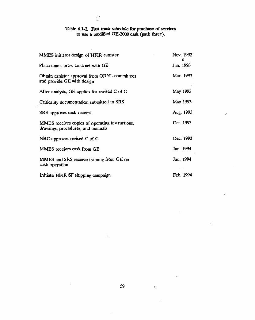
Table 6.1 -Z Fast track schedule for purchase of services to use a modified GE-2000 cask (path three).
MMES initiates design of HFIR canister Nov. 1992 f!
Place emer. prov. contract with GE Jan. 1993
Obtain canister approval from ORNL committees Mar. 1993 and provide GE with design
After analysis, GE applies for revised C of C May 1993
Criticality documentation submitted to SRS May 1993
SRS approves cask receipt Aug. 1993
MMES receives copies of operating instructions, Oct. 1993 drawings, procedures, and manuals
NRC approves revised C of C Dec. 1993
MMES receives cask from GE Jan. 1994
MMES and SRS receive training from GE on Jan. 1994 cask operation
Initiate HFIR SF shipping campaign Feb. 1994
59
6.2 Regulatory and Other Requirements
6.2.1 Safeguards and Security Requirements
As described in Section 2.1, the HFIR spent fuel is an attractiveness level E material. Therefore
an unlimited amount of HFIR spent fuel could be transported in a shipping cask with minimal
safeguard and security requirements.
6.2.2 NEPA Requirements
NEPA requirements are summarized in Section 2.2 of this report. Transportation is generally
covered under NEPA only as it is related to a process covered by NEPA documentation. In the «
case of shipment of HFIR spent fuel to SRS, NEPA documentation at SRS should cover these
shipments. The shipments in and of themselves do not invoke NEPA documentation
requirements.
6.2.3 RCRA Requirements
RCRA requirements do not apply to transport of fuel to SRS.
6.2.4 Transportation Requirements
As discussed in Section 2.4 of this report, offsite transport of HFIR spent fuel requires use of a
DOE- or NRC-certified shipping container. At this time, no shipping containers are certified by
either DOE or the NRC to ship the HFIR spent fuel. Section 6.1 of this report describes in
some depth the efforts being made to obtain a certified shipping container, and points out that all
of the options have potential pitfalls that may make it impossible to ship the HFIR fuel as a
short-term alternative. However the potential benefits should one of the efforts be successful, as
well as the uncertainty that any other option can be successful in the short term, make it
important to continue to pursue the offsite shipment alternative.
6 0
6.2.5 Safety Documentation Requirements
To obtain a DOE or NRC Certificate of Compliance (CofC) requires preparation, review and
approval of a Safety Analysis Report for Packaging (SARP). The options being pursued call for ,
either preparation of a new SARP for a new shipping container, or revision of an existing SARP
for a container which is certified to carry other radioactive material. If the SARP has to go
before DOE for approval, the chances of success in the short term are very slim. DOE has a
record of approving very few shipping containers, and taking many years to complete the review i[
cycle. The GNSI design has already been in the DOE review cycle for several years. For the GE
cask options, if DOE insists upon reviewing the SARP internally before GE sends proposed
revisions to NRC for approval, GE has reported that they will drop any attempt to get a
modification to their CofC. That is, they will not permit DOE to independently review their
shipping container. Therefore DOE's insistence upon reviewing the container will ensure failure
of this option.
6.2.6 Nuclear Criticality Safety Requirements
A nuclear criticality review will be required as a part of the SARP for any shipping container.
SRS has also reported that they may require additional criticality analysis before ORNL resumes
shipments of HFIR spent fuel to SRS, and HFIR. will have to provide a similar analysis at ORNL.
This was discussed in Section 6.1.
6.3 Cost Estimates
Cost estimates developed for the purchase of a modified GE-2000 cask and the purchase of
services to use such a cask are given in Tables 6.3-1 and 6.3-2.
6.4 Feasibility of Offsite Options as Short-Term Alternative
Shipment of HFIR spent fuel assemblies offsite appears to be feasible if an approved shipping
cask can be obtained. Discussions with GE on the option to purchase a modified cask outright or
to purchase the services of such a cask are progressing well at this time.
61
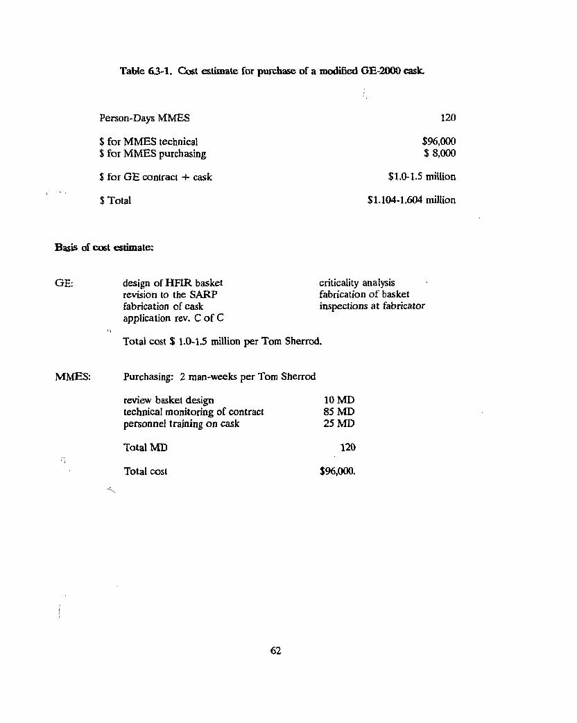
Table 63-1. Cost estimate for purchase of a modified GE-2000 cask.
Person-Days MMES 1 2 0
$ for MMES technical $ for MMES purchasing
$ for GE contract + cask
$ Total
$96,000 $ 8,000
$1.0-1.5 million
$1,104-1.604 million
Basis of cost estimate:
GE: design of HFIR basket revision to the SARP fabrication of cask application rev. C of C
criticality analysis fabrication of basket inspections at fabricator
Total cost $ 1.0-1.5 million per Tom Sherrod.
MMES: Purchasing: 2 man-weeks per Tom Sherrod
review basket design 10 MD technical monitoring of contract 85 MD personnel training on cask 25 MD
Total MD 120 • /
Total cost $96,000.
62
Table 63-2. Cost estimate for purchase of services of a modified GE-2000 cask.
Person days MMES 40 MD @ $100/hr $ MMES technical $32,000 $ MMES canister fabrication $10,000
$ for lease of GE cask if needed $45,000 $ total without cask lease $42,000 $ total with GE cask lease , $87,000
Basis of estimates:
MMES: Purchasing charges for emergency contract with GE 10 MD Revised canister design 25 MD monitoring design and interaction with X-10 committees 5 MD fabrication of canister $10,000 Total MD 40 @ $100/hr;
Total MMES cost 42,000.
GE: Est. cost of emergency contract
Lease cost of $l,500/cask day, minimum 30 day use
63
An early decision by DOE to completely shut down reprocessing at the SRS, or to discontinue
reprocessing of the fuels stored at the RBOF, would reduce the incentive to pursue offisite
shipping of the HFIR fuel. Despite these potential problems, this option should not be
abandoned. It is the only alternative other than expansion of HFIR pool storage that has any
chance of success in the short term. Because neither of these options is certain of success, both
should be aggressively pursued.
64
7. Recommendations
Table 7.0-1 lists the various options studied, the issues involved with each option, and the date by
which each might be achievable. Three spent fuel management options should be vigorously
pursued:
( 1 ) H F I R pool storage expansion,
(2) shipment offsite to SRS, and
(3) dry cask storage.
The first ,*wo options are the only management alternatives that may be achievable in the short
term. The third option has the highest probability of success as an intermediate-term solution.
For HFIR pool storage to be achievable in the short term, a very fast-track program would have
to be implemented. This fast-track program is feasible only if:
— the project is subject to Categorical Exclusion (CX) so that an EA or EIS is not
required,
— capital funds are immediately available,
— existing radioactive waste in the pool can successfully be turned over to the Waste
Management and Remedial Action (WMRA) Division,
— existing RRD Quality Assurance (QA) requirements can be used, and
— both ORNL and DOE can process necessary documents in extremely short times.
Failure in any one of these areas would jeopardize continued HFIR operation.
Shipment to SRS depends on:
— the ability to obtain a DOE- or NRC-certified shipping container approved to ship
the HFIR spent fuel, and
— continuation of the reprocessing program at SRS.
Neither of these is a certainty at this time. Obtaining a DOE certificate of compliance is
extremely expensive and time-consuming. Recent efforts to obtain a DOE-certified shipping
container have been unsuccessful so far, and do not appear likely to be successful in time to
65
Table 7.0-1. HFIR spent fuel management alternatives
Alternative Issues Achievable timeframe
Re-rack HFIR pool •Operating concerns •Criticality •Corrosion
May be achievable by 1/95.
Ship to SRS •Package certification and availability •SRS willingness to accept •May be limited to 20 assemblies
May be achievable by 2/94.
Other ORNL pools •Criticality •Corrosion •NEPA •Safety documentation •Transfer system •ORR: ; Transfer to EM
Floor loading •BSR: Crane capacity
Floor loading Safeguards & security
•TSR: Water chemistry control Containment
Not achievable in short term. Poor option compared to others for intermediate term. 1
Hot cell storage •Criticality •Heat removal •Transfer system •Shielding •Structural integrity •NEPA •Safety documentation
Not achievable in short term. 7930 may be achievable by 7/97.
Dry cask storage •Transfer system •Procurement (capital) •NEPA •Safety documentation
May be achievable by 8/96.
support offsite shipment of the HFIR spent fuel as a short-term management alternative.
Obtaining an NRC-certified shipping container from GE may be made impossible if DOE/HQ
insists upon reviewing and approving an application for modification to an NRC Certificate of
Compliance before the application goes to NRC. GE has already indicated their unwillingness to
subject their NRC-certified container to DOE review. As for continuation of reprocessing at
SRS, discussions at DOE/EM are underway at this time regarding the possibility of shutting down
the SRS reprocessing program in the near future.
Even if they can be implemented, both of the above options are temporary solutions. Even if the
HFIR pool expansion is successful and triple stacking can be achieved in both the east pool and
the critical pool, HFIR will still run out of space by July 2004. Filling the pools to their capacity
has the further disadvantage of severely restricting operations in the HFIR pools. Shipment off-
site to SRS is likely to be stopped by DOE/EM actions by the end of FY 1996, and may end
significantly sooner.
Because of the temporary nature of the short-term solutions, as well as the problems potentially
encountered with each, dry cask storage should be pursued as an intermediate-term solution. Dry
cask storage has the potential to provide a great deal of operational flexibility, and can be
designed with sufficient capacity to keep HFIR in operation through its expected operating life.
As a new facility design, it has a greater probability of success in obtaining approval from DOE
for required NEPA and safety documentation in reasonably short time frames. If an NRC license
is required of the vendor for the cask design, the DOE safety documentation process should be
shortened appreciably. 1
As for the other management alternatives investigated, all have significant potential problems in
both the short term and the intermediate term. Problems with storing the HFIR spent fuel in any
of the other ORNL pools include the need for significant NEPA and safety documentation, as
well as the need to rectify significant physical inadequacies in these facilities. ORNL hot cell
storage has the same problems. Resolving these problems for any of these facilities is expected to
result in costs and schedules which compare unfavorably with the dry cask storage alternative.
67
Appendix A
Contacts Developed During the Course of This Stud}'
The list of dry cask storage vendors is given in Table 3.1-1.
.trb Tfr' Intermim Storape Cask Lee Besel, Westinghouse Hanford technical contact: 509-376-4219 Darla Vance, buyer: 509-376-5215
Hot Cells Emory Collins, CTD, REDC: 574-6928 AlanJCrichinsky, CTD, 3019: 574-6940 Bob Eversole, CTD, Isotope Facility Shutdown Plan: 576-7483 Robin Taylor, ORNL, 3525: 574-7111
Criticality. Shielding and Source Terms Dowe Dabbs, RRD: 576-5582 Scott Ludwig, CTD: 574-7916
Solid Waste Storage Areas Harold Adair, WMRAD: 574-5900 Bob Forgy, WMRAD: 576-5223 Bob Mason, WMRAD: 574-1365
Shipment Offsite Bill Dennis, DOE/SR: 803-725-5546 Sachiko McAlhany, DOE/SR RBOF: 803-725-5535 Matt Beckum, Westinghouse SR RBOF: 803-557-8773 Henry Walter, DOE/HQ-EM: 301-903-7414 Chris Wennes, BNL HFBR: 516-282-4701 Joe Ratledge, CTD: 574-8368 Larry Shappert, CTD: 576-2066 Todd Tillinghast, GE: 510-862-4396
Pool Storage Leo Holland, RRD: 574-7210 Gary Coleman, RRD: 574-6997 Roger Stover, RRD: 574-8544 Dowe Dabbs, RRD: 576-5582 Emory Collins, CTD: 574-6928
RCRA Nancy Dailey, ORNL: 574-8774
A-1
NEPA Marie Saint-Louis, CTD: 574-9183 Frank Kornegay, ORNL: 574-5776 James Hall, ORNL: 576-1293 Mike Jansky, Westinghouse Hanford NEPA Coordinator: 509-376-0202 Rich Saylor, ORNL: 574-0578
Safety Documentation Mike Green, MMES Engineering: 574-8260 Mickie Crowley, MMES Engineering: 574-6495 Mark Kohring, ORNL: 574-5505 Milt Kreger, ORNL: 574-7572
Safeguards and Security Bill Rich, ORNL: 574-7024 Randy Roberts, ORNL: 574-7023 Jim Hargrove, ORNL: 574-7017
Siting for Drv Storage Steve McNeany, ORNL Space Coordinator: 574-9288 , Steve Burnette, RRD: 576-0214 Walt Brown, RRD: 574-3333
Purchasing Tom Sherrod: 576-1468 Mary Hawn: 576-1429 Bonnie Moses: 576-1458 Ralph Waddell: 574-3807
Project Management John Murray, MMES Engineering: 576-6430
A-2
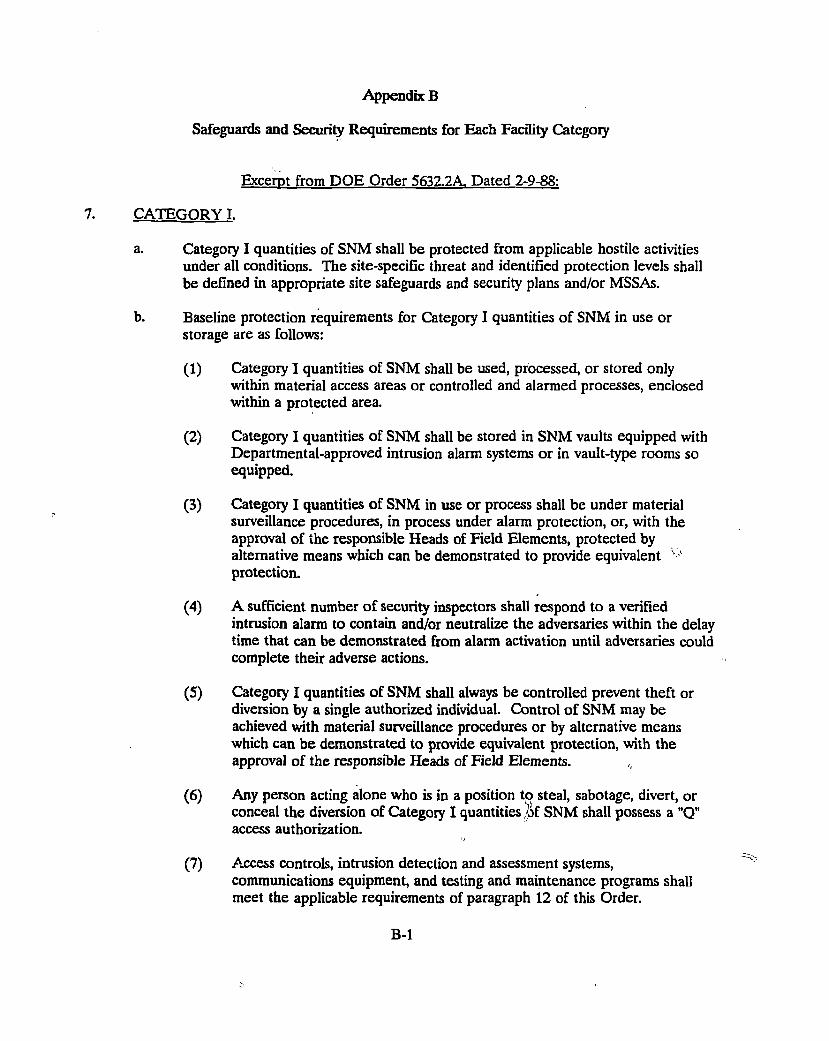
Appendix B
Safeguards and Security Requirements for Each Facility Category
Excerpt from DOE Order 5632.2A. Dated 2-9-88:
CATEGORY I.
a. Category I quantities of SNM shall be protected from applicable hostile activities under all conditions. The site-specific threat and identified protection levels shall be defined in appropriate site safeguards and security plans and/or MSSAs.
b. Baseline protection requirements for Category I quantities of SNM in use or storage are as follows:
(1) Category I quantities of SNM shall be used, processed, or stored only within material access areas or controlled and alarmed processes, enclosed within a protected area.
(2) Category I quantities of SNM shall be stored in SNM vaults equipped with Departmental-approved intrusion alarm systems or in vault-type rooms so equipped.
(3) Category I quantities of SNM in use or process shall be under material surveillance procedures, in process under alarm protection, or, with the approval of the responsible Heads of Field Elements, protected by alternative means which can be demonstrated to provide equivalent v
protection.
(4) A sufficient number of security inspectors shall respond to a verified intrusion alarm to contain and/or neutralize the adversaries within the delay time that can be demonstrated from alarm activation until adversaries could complete their adverse actions.
(5) Category I quantities of SNM shall always be controlled prevent theft or diversion by a single authorized individual. Control of SNM may be achieved with material surveillance procedures or by alternative means which can be demonstrated to provide equivalent protection, with the approval of the responsible Heads of Field Elements.
(6) Any person acting alone who is in a position to steal, sabotage, divert, or conceal the diversion of Category I quantities of SNM shall possess a "Q" access authorization.
(7) Access controls, intrusion detection and assessment systems, communications equipment, and testing and maintenance programs shall meet the applicable requirements of paragraph 12 of this Order.
B-1
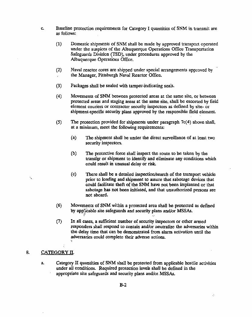
c. Baseline protection requirements for Category I quantities of SNM in transmit are as follows:
(1) Domestic shipments of SNM shall be made by approved transport operated under the auspices of the Albuquerque Operations Office Transportation Safeguards Division (TSD), under procedures approved by the Albuquerque Operations Office.
(2) Naval reactor cores are shipped under special arrangements approved by the Manager, Pittsburgh Naval Reactor Office.
(3) Packages shall be sealed with tamper-indicating seals.
(4) Movements of SNM between protected areas at the same site, or between protected areas and staging areas at the same site, shall be escorted by field element couriers or contractor security inspectors as defined by site- or shipment-specific security plans approved by the responsible field element.
(5) The protection provided for shipments under paragraph 7c(4) above shall, at a minimum, meet the following requirements:
(a) The shipment shall be under the direct surveillance of at least two security inspectors.
(b) The protective force shall inspect the route to be taken by the transfer or shipment to identify and eliminate any conditions which could result in unusual delay or risk.
(c) There shall be a detailed inspection/search of the transport vehicle prior to loading and shipment to assure that sabotage devices that could facilitate theft of the SNM have not been implanted or that sabotage has not been initiated, and that unauthorized persons are not aboard.
(6) Movements of SNM within a protected area shall be protected as defined by applicable site safeguards and security plans and/or MSSAs.
(7) In all cases, a sufficient number of security inspectors or other armed responders shall respond to contain and/or neutralize the adversaries within the delay time that can be demonstrated from alarm activation until the adversaries could complete their adverse actions. V
8. CATEGORY H
a. Category II quantities of SNM shall be protected from applicable hostile activities under all conditions. Required protection levels shall be defined in the appropriate site safeguards and security plans and/or, MSSAs.
B-2
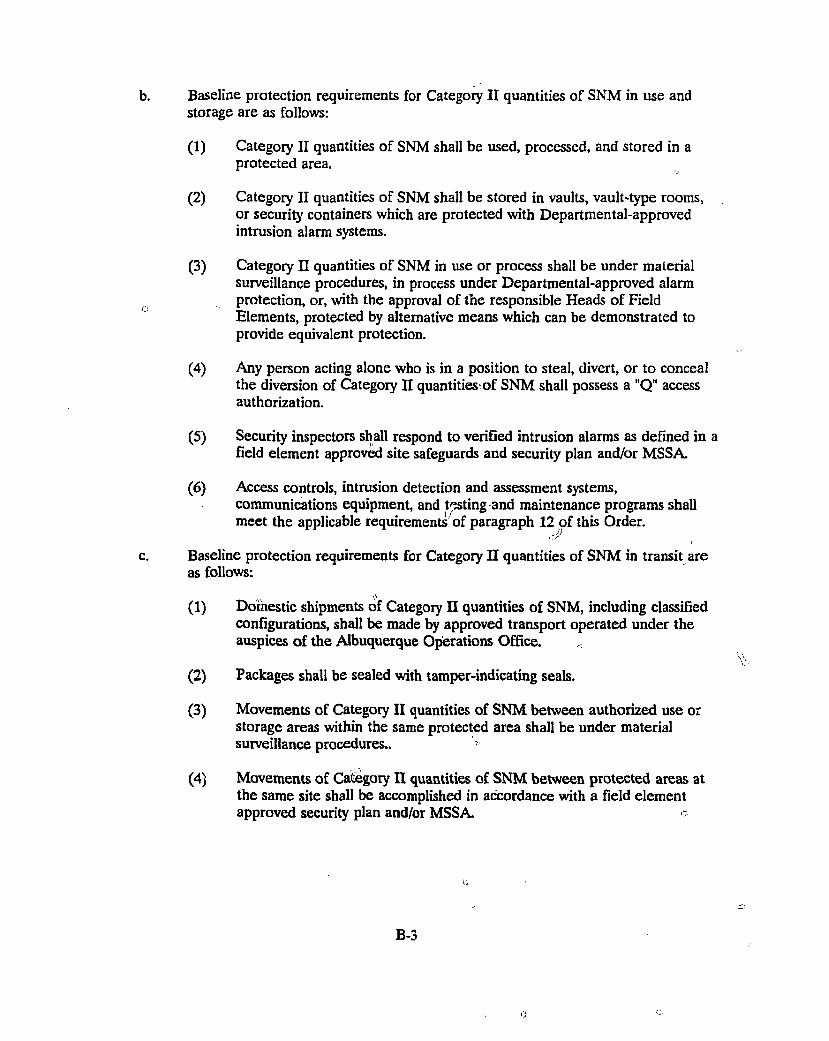
Baseline protection requirements for Category II quantities of SNM in use and storage are as follows:
(1) Category II quantities of SNM shall be used, processed, and stored in a protected area.
(2) Category II quantities of SNM shall be stored in vaults, vault-type rooms, or security containers which are protected with Departmental-approved intrusion alarm systems.
(3) Category II quantities of SNM in use or process shall be under material surveillance procedures, in process under Departmental-approved alarm protection, or, with the approval of the responsible Heads of Field Elements, protected by alternative means which can be demonstrated to provide equivalent protection.
(4) Any person acting alone who is in a position to steal, divert, or to conceal the diversion of Category II quantities-of SNM shall possess a "Q" access authorization.
(5) Security inspectors shall respond to verified intrusion alarms as defined in a field element approved site safeguards and security plan and/or MSSA.
(6) Access controls, intrusion detection and assessment systems, communications equipment, and testing and maintenance programs shall meet the applicable requirements of paragraph this Order.
Baseline protection requirements for Category II quantities of SNM in transit are as follows:
(1) Domestic shipments of Category II quantities of SNM, including classified configurations, shall be made by approved transport operated under the auspices of the Albuquerque Operations Office.
(2) Packages shall be sealed with tamper-indicating seals.
(3) Movements of Category II quantities of SNM between authorized use or storage areas within the same protected area shall be under material surveillance procedures..
(4) Movements of Category II quantities of SNM between protected areas at the same site shall be accomplished in accordance with a field element approved security plan and/or MSSA c
B-3
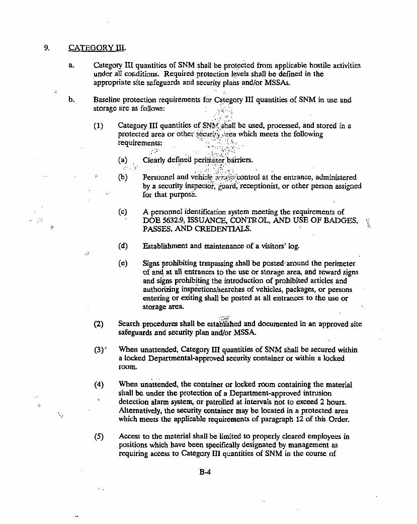
CATEGORY III.
a. Category III quantities of SNM shall be protected from applicable hostile activities under all conditions. Required protection levels shall be defined in the appropriate site safeguards and security plans and/or MSSAs.
b. Baseline protection requirements for Category III quantities of SNM in use and storage are as follows: j
.'I' >''
(1) Category III quantities of SN '̂fi shall be used, processed, and stored in a protected area or other: security'«rjea which meets the following requirements: ' ' ' ' I K > . . .
(a) Clearly defined perimtiter barriers.
(b) Personnel and vehicle ;V;ceffi(control at the entrance, administered by a security inspector, guard, receptionist, or other person assigned for that purpose.
(c) A personnel identification system meeting the requirements of DOE 5632.9, ISSUANCE, CONTR OL, AND USE OF BADGES, PASSES, AND CREDENTIALS.
(d) Establishment and maintenance of a visitors' log.
(e) Signs prohibiting trespassing shall be posted around the perimeter of and at all entrances to the use or storage area, and reward signs and signs prohibiting the introduction of prohibited articles and authorizing inspections/searches of vehicles, packages, or persons entering or exiting shall be posted at all entrances to the use or storage area.
(2) Search procedures shall be established and documented in an approved site safeguards and security plan and/or MSSA
(3)' When unattended, Category III quantities of SNM shall be secured within a locked Departmental-approved security container or within a locked room.
(4) When unattended, the container or locked room containing the material shall be under the protection of a Department-approved intrusion detection alarm system, or patrolled at intervals not to exceed 2 hours. Alternatively, the security container may be located in a protected area which meets the applicable requirements of paragraph 12 of this Order.
(5) Access to the material shall be limited to properly cleared employees in positions which have been specifically designated by management as requiring access to Category III quantities of SNM in the course of
B-4
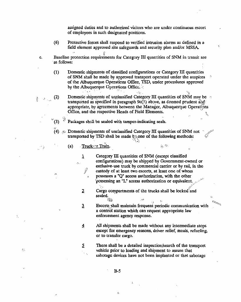
assigned duties and to authorized visitors who are under continuous escort of employees in such designated positions.
(6) Protective forces shall respond to verified intrusion alarms as defined in a field element approved site safeguards and security plan and/or MSSA.
Baseline protection requirements for Category III quantities of SNM in transit are as follows:
(1) Domestic shipments of classified configurations or Category III quantities of SNM shall be made by approved transport operated under the auspices of the Albuquerque Operations Office, TSD, under procedures approved by the Albuquerque Operations Office:! ..
(2) Domestic shipments of unclassified Category III quantities of SNM may be transported as specified in paragraph 9c(7 ) above, as deemed prudent and/ appropriate, by agreements between the Manager, Albuquerque Operations Office, and the respective Heads of Field Elements. ' ^
U'. V/ " (3) Packages shall be sealed with tamper-indicating seals. '.V (4) ^ Domestic shipments of unclassified Category III quantities of SNM not
transported by TSD shall be made by.one of the following methods: i 0
(a) Trucker Train. %
1 Category III quantities of SNM (except classified _ configurations) may be shipped by Government-owned or
exclusive-use truck by commercial carrier or by rail, in the J/ custody of at least two escorts, at least one of whom
>, possesses a "Q" access authorization, with the other possessing an "L" access authorization or equivalent. •
/ 2 Cargo compartments of the trucks shall be locked and
sealed. ^ - - u
3 Escorts shall maintain frequent periodic communication with ; a control station which can request appropriate law
enforcement agency response.
4 All shipments shall be made without any intermediate stops except for emergency reasons, driver relief, meals, refueling, or to transfer cargo.
5 There shall be a detailed inspection/search of the transport vehicle prior to loading and shipment to assure that sabotage devices have not been implanted or that sabotage
B-5
o
has not been initiated and that unauthorized persons are not aboard.
(b) Air shipments of Category III quantities of SNM may take place if not otherwise prohibited by statute or implementing instructions. The material must be attended by at least two escorts, at least one of whom possesses a "Q" access authorization, with the other possessing at least "L" access authorization or equivalent. The shipments must be under the direct observation of the escorts during all land movements and loading and unloading operations.
(5) Movements of Category III quantities of SNM between security areas at the same site shall be accomplished in accordance with a field element approved security plan.
ir
10. CATEGORY IV.
a. Category IV quantities of SNM shall be protected from applicable hostile activities. The defined level of protection shall be described in appropriate site safeguards and security plans and/or MSSAs.
b. Category IV quantities of SNM shall be received, used, processed, and stored in accordance with field element approved security plans.
c. Baseline requirements for protection of Category IV quantities of SNM in transit are as follows:
( 1 ) D o m e s t i c shipments of Category IV quantities of SNM, including classified configurations, may be made by approved transport operated under the auspices of the Albuquerque Operations Office, TSD, under procedures approved by the Albuquerque Operations Office, as deemed appropriate and by agreements between the Manager, Albuquerque Operations Office, and the respective Heads of Field Elements.
(2) Shipments of all Category IV quantities of SNM not transported by TSD may be made by one of the following methods: truck; rail, air, or water in commercial, for-hire vehicles. (If not otherwise prohibited by statue or implementing instructions, air shipments of Category IV quantities of SNM may take place.)
(3) Packages shall be sealed with tamper-indicating seals.
(4) Shipments, excepting shipments of laboratory analysis samples or reference materials, shall be made under arrangements which provide the capability to trace and identify, within 24 hours of request, the precise leg of a journey where a shipment went astray in the event of its nonarrival at destination within the prescribed time frame.
B - 6
G
(5) Advance notification of the estimated time of arrival to be received prior to dispatch, with written confirmation following not latter than 48 hours after dispatch, shall be provided by the shipper to the consignee.
(6) The consignee shall promptly notify the shipper by telephone upon determination that a shipment has not arrived within a reasonable time, based on shipping method and expected deliver date, and shall provide written confirmation of such notification.
(7) Shipments shall be made in accordance with all applicable Federal regulations.
11. VITAL EQUIPMENT.
a. Vital equipment shall be protected from the applicable hostile activities under all conditions. The site-specific threat and identified protection levels shall be define in appropriate site safeguards and security plans and/or MSSAs.
b. All vital equipment shall be contained within defined vital areas, which are located within protected areas.
c. A sufficient number of security inspectors shall respond to alarms to contain and/or neutralize the adversaries within the delay time that can be demonstr; from alarm activation until adversaries could complete their adverse actions.
r j;
Access controls, intrusion detection and assessment systems, communications equipment, and testing and maintenance programs shall meet the applicable requirements of paragraph 12 of this Order.
12. FACILITIES WITH CATEGORY I OR II QUANTITIES OF SNM OR VITAL EQUIPMENT.
a. Access Controls at Security Areas.
(1) Security areas shall be established to protect SNM and vital equipment as follows:
(a) A protected areas shall be established to control Category I and II quantities of SNM and to provide protection for vital equipment.
* (
(b) Material access areas or controlled and alarmed processes shall be established to control access to areas containing Category I quantities of SNM.
(c) Vital areas shall be established to provide protection for vital equipment.
B-7
(d) Central alarm station access control areas shall be established to protect alarm monitoring and communications capabilities.
Protected Area Access Controls.
(a) Barriers.
B - 8
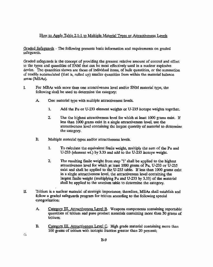
How to Apply Table 2.1-1 to Multiple Material Types or Attractiveness Levels
Graded Safeguards - The following presents basic information and requirements on graded safeguards.
Graded safeguards is the concept of providing the greatest relative amount of control and effort to the types and quantities of SNM that can be most effectively used in a nuclear explosive device. The quantities shown are those of individual items, of bulk quantities, or the summation of readily accumulated (that is, rolled up) smaller quantities from within the material balance areas (MBAs).
I. For MBAs with more than one attractiveness level and/or SNM material type, the following shall be used to determine the category:
A One material type with multiple attractiveness levels.
1. Add the Pu or U-233 element weights or U-235 isotope weights together.
2. Use the highest attractiveness level for which at least 1000 grams exist. If less than 1000 grams exist in a single attractiveness level, use the attractiveness level containing the largest quantity of material to determine the category.
B. Multiple materia] types and/or attractiveness levels.
1. To calculate the equivalent fissile weight, multiply the sum of the Pu and U-233 (element wt.) by 3.33 and add to the U-235 isotope weight.
2. The resulting fissile weight from step "1" shall be applied to the highest attractiveness level for which at least 1000 grams of Pu, U-233 or U-235 exist and shall be applied to the U-235 table. If less than 1000 grams exist in a single attractiveness level, the attractiveness level containing the largest fissile weight (multiplying Pu and U-233 by 3.33) of the material shall be applied to the uranium table to determine the category.
II. Tritium is a nuclear material of strategic importance; therefore, MBAs shall establish and follow a graded safeguards program for tritium according to the following special categorization:
A. Category III, Attractiveness Level B. Weapons components containing reportable quantities of tritium and pure product materials containing more than 50 grams of tritium;
B. Category III. Attractiveness Level C. High grade material containing more than 100 grams of tritium with isotopic fraction greater than 20 percent;
B-9
Category III, Attractiveness level r> Recoverable low grade materials containing greater than 150 grams of tritium with isotopic fraction of 20 percent or less; and
Category IV. All other reportable quantities, isotopic fractions, types and forms of tritium.
B-10
Appendix C Information from Dry Cask Storage Vendors
The list of dry cask storage vendors (or in a couple of cases, consultants knowlegeable about dry cask
storage) contacted was given in Table 3.1-1. Five vendors actually have visited the HFIR to date.
A summary of the information obtained from the five (plus information obtained concerning the
AECL Technologies system) was given in Table 3.1-2.
Prior to the vendor visits, a question sheet was prepared to use for discussion purposes with each
vendor. These questions are shown in Table Cl. The remainder of this appendix will be devoted
to the information obtained from each vendor.
Tables C2 through C7 give the questions (Qx) and answers (Ax) based on Table Cl. If the answer
is left blank, no information was obtained for that question. The typical format for each vendor visit
included the following:
Time for introductions
Discussion of the HFIR spent fuel storage needs
Discussion of the vendor dry cask storage system
Tour of the HFIR
Wrapup 1
(i
C-l
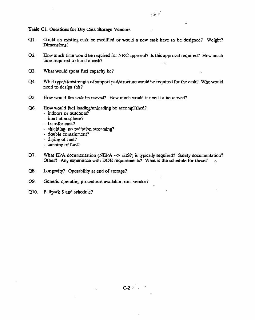
Table CI. Questions for Dry Cask Storage Vendors >
Ql. Could an existing cask be modified or would a new cask have to be designed? Weight? Dimensions?
Q2. How much time would be required for NRC approval? Is this approval required? How much time required to build a cask?
Q3. What would spent fuel capacity be?
Q4. What type/size/strength of support pad/structure would be required for the cask? Who would need to design this?
Q5. How would the cask be moved? How much would it need to be moved?
Q6. How would fuel loading/unloading be accomplished? - indoors or outdoors? - inert atmosphere? - transfer cask? - shewing! no radiation streaming? - double containment? - drying of fuel? - canning of fuel?
Q7. What EPA documentation (NEPA ~ > EIS?) is typically required? Safety documentation? Other? Any experience with DOE requirements? What is the schedule for these?
Q8. Longevity? Operability at end of storage?
Q9. Generic operating procedures available from vendor?
Q10. Ballpark $ and schedule?
C-2 -
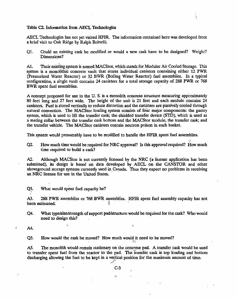
Table C2. Information from AECL Technologies
AECL Technologies has not yet visited HFIR. The information contained here was developed from a brief visit to Oak Ridge by Ralph Brittelli.
Ql. Could an existing cask be modified or would a new cask have to be designed? Weight? Dimensions?
Al. Their existing system is named MACStor, which stands for Modular Air Cooled Storage. This system is a monolithic concrete vault that stores individual canisters containing either 12 PWR (Pressurized Water Reactor) or 32 BWR (Boiling Water Reactor) fuel assemblies. In a typical configuration, a single vault contains 24 canisters for a total storage capacity of 288 PWR or 768 BWR spent fuel assemblies.
A concept proposed for use in the U. S. is a monolith concrete structure measuring approximately 80 feet long and 27 feet wide. The height of the unit is 21 feet and each module contains 24 canisters. Fuel is stored vertically to reduce distortion and the canisters are passively cooled through natural convection. The MACStor loading system consists of four major components: the gantry system, which is used to lift the transfer cask; the shielded transfer device (STD), which is used as a mating collar between the transfer cask bottom and the MACStor module; the transfer cask; and the transfer vehicle. The MACStor canisters contain neutron poison in each basket.
This system would presumably have to be modified to handle the HFIR spent fuel assemblies. 17 ,
Q2. How much time would be required for NRC approval? Is this approval required? How much time required to build a cask?
A2. Although MACStor is not currently licensed by the NRC (a license application has been submitted), its design is based on data developed by AECL on the CANSTOR and other aboveground storage systems currently used in Canada. Thus they expect no problems in receiving an NRC license for use in the United States.
Q3. What would spent fuel capacity be?
A3. 288 PWR assemblies or 768 BWR assemblies. HFIR spent fuel assembly capacity has not been estimated. (I
Q4. What type/size/strength of support pad/structure would be required for the cask? Who would need to design this?
Q5. How would the cask be moved? How much would it need to be moved? cs A5. The monolith would remain stationary on the concrete pad. A transfer cask would be used to transfer spent fuel from the reactor to the pad. The transfer cask is top loading and bottom discharging allowing the fuel to be kept in a vertical position for the maximum amount of time.
C-3
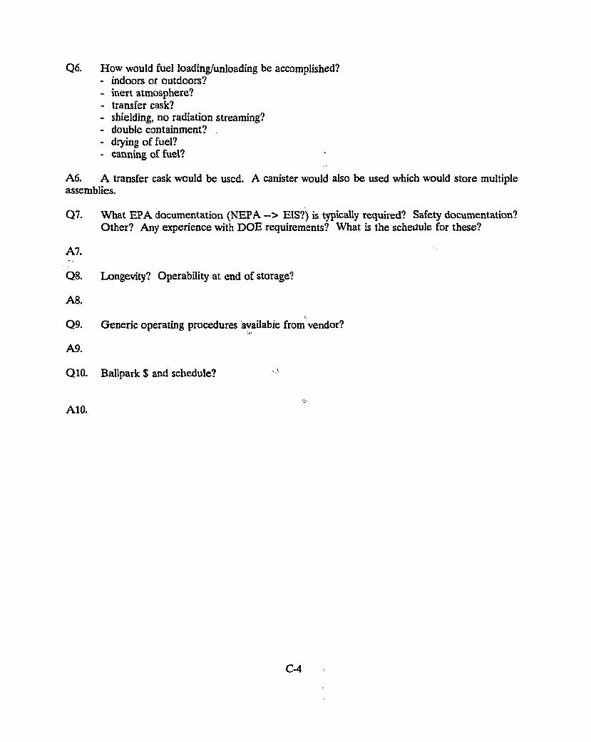
Q6. How would fuel loading/unloading be accomplished? - indoors or outdoors? - inert atmosphere? - transfer cask? - shielding, no radiation streaming? - double containment? - drying of fuel? - canning of fuel?
A6. A transfer cask would be used. A canister would also be used which would store multiple assemblies.
Q7. What EPA documentation (NEPA --> EIS?) is typically required? Safety documentation? Other? Any experience with DOE requirements? What is the schedule for these?
A7.
Q8. Longevity? Operability at end of storage?
A8.
Q9. Generic operating procedures available from vendor?
A9.
Q10. Ballpark $ and schedule? 1
A10.
C-4
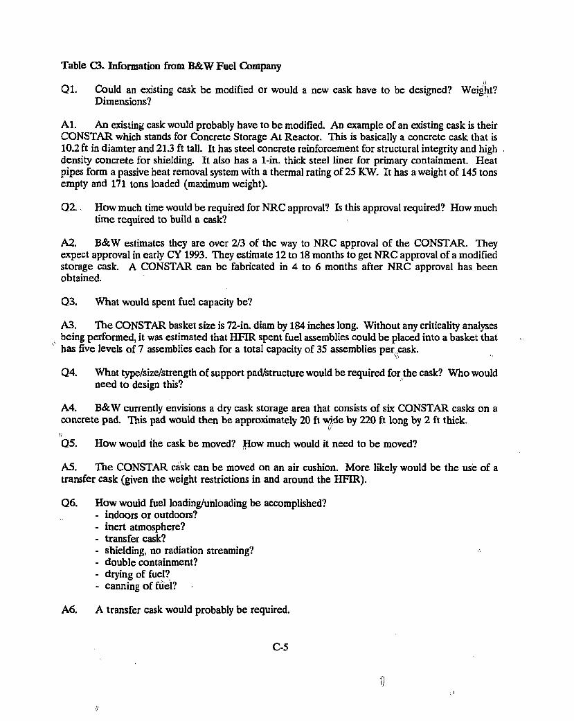
Table C3. Information from B&W Fuel Company _ // Ql. Could an existing cask be modified or would a new cask have to be designed? Weight?
Dimensions?
Al. An existing cask would probably have to be modified. An example of an existing cask is their CONSTAR which stands for Concrete Storage At Reactor. This is basically a concrete cask that is 10.2 ft in diamter and 21.3 ft tall. It has steel concrete reinforcement for structural integrity and high density concrete for shielding. It also has a 1-in. thick steel liner for primary containment. Heat pipes form a passive heat removal system with a thermal rating of 25 KW. It has a weight of 145 tons empty and 171 tons loaded (maximum weight).
Q2. How much time would be required for NRC approval? Is this approval required? How much time required to build a cask?
A2. B&W estimates they are over 2/3 of the way to NRC approval of the CONSTAR. They expect approval in early CY 1993. They estimate 12 to 18 months to get NRC approval of a modified storage cask. A CONSTAR can be fabricated in 4 to 6 months after NRC approval has been obtained.
Q3. What would spent fuel capacity be?
A3. The CONSTAR basket size is 72-in. diam by 184 inches long. Without any criticality analyses being performed, it was estimated that HFIR spent fuel assemblies could be placed into a basket that has five levels of 7 assemblies each for a total capacity of 35 assemblies per,cask.
Q4. What type/size/strength of support pad/structure would be required for the cask? Who would need to design this?
A4. B&W currently envisions a dry cask storage area that consists of six CONSTAR casks on a concrete pad. This pad would then be approximately 20 ft wide by 220 ft long by 2 ft thick. I! ' Q5. How would the cask be moved? How much would it need to be moved?
A5. The CONSTAR cask can be moved on an air cushion. More likely would be the use of a transfer cask (given the weight restrictions in and around the HFIR).
Q6. How would fuel loading/unloading be accomplished? - indoors or outdoors? - inert atmosphere? - transfer cask? - shielding, no radiation streaming? - double containment? - drying of fuel? - canning of fuel?
A6. A transfer cask would probably be required.
C-5
!/
//
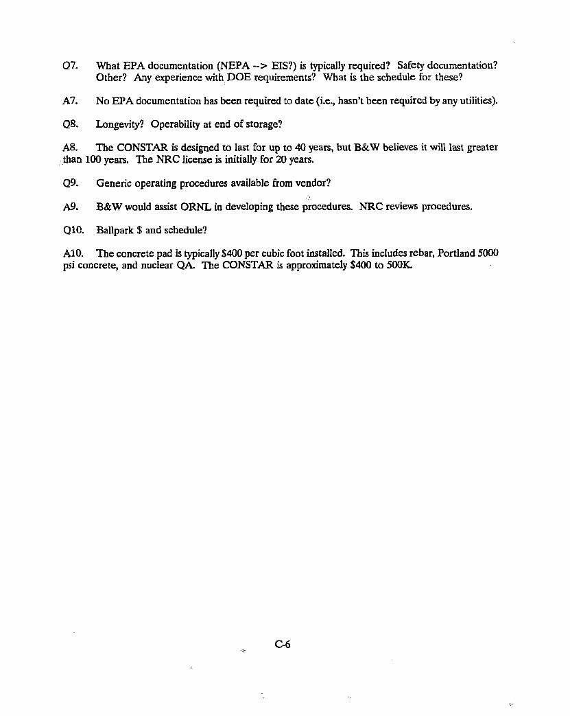
Q7. What EPA documentation (NEPA --> EIS?) is typically required? Safety documentation? Other? Any experience with DOE requirements? What is the schedule for these?
A7. No EPA documentation has been required to date (i.e., hasn't been required by any utilities).
Q8. Longevity? Operability at end of storage?
A8. The CONSTAR is designed to last for up to 40 years, but B&W believes it will last greater than 100 years. The NRC license is initially for 20 years.
Q9. Generic operating procedures available from vendor?
A9. B&W would assist ORNL in developing these procedures. NRC reviews procedures.
Q10. Ballpark $ and schedule?
A10. The concrete pad is typically $400 per cubic foot installed. This includes rebar, Portland 5000 psi concrete, and nuclear QA. The CONSTAR is approximately $400 to 500K
C-6
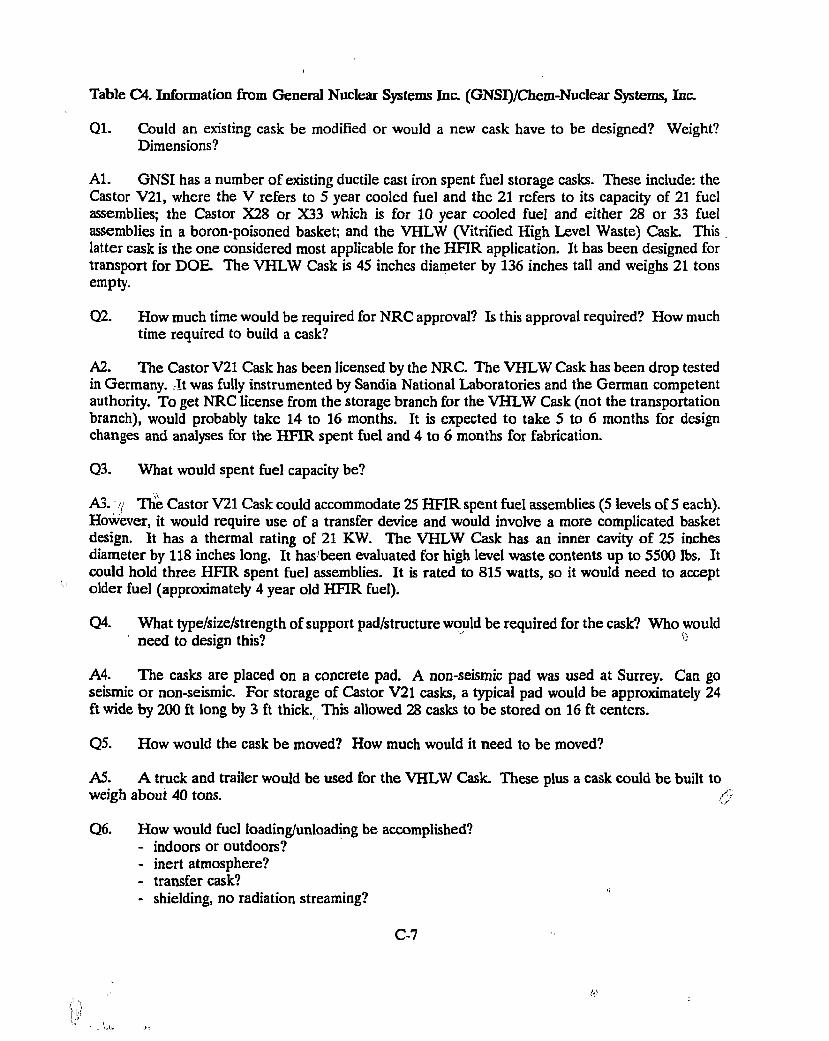
Table C4. Information &om General Nuclear Systems Inc. (GNSI)/Chem-Nuclear Systems, Inc.
Ql. Could an existing cask be modified or would a new cask have to be designed? Weight? Dimensions?
Al. GNSI has a number of existing ductile cast iron spent fuel storage casks. These include: the Castor V21, where the V refers to 5 year cooled fuel and the 21 refers to its capacity of 21 fuel assemblies; the Castor X28 or X33 which is for 10 year cooled fuel and either 28 or 33 fuel assemblies in a boron-poisoned basket; and the VHLW (Vitrified High Level Waste) Cask. This latter cask is the one considered most applicable for the HFIR application. It has been designed for transport for DOE. The VHLW Cask is 45 inches diameter by 136 inches tall and weighs 21 tons empty.
Q2. How much time would be required for NRC approval? Is this approval required? How much time required to build a cask?
A2. The Castor V21 Cask has been licensed by the NRC. The VHLW Cask has been drop tested in Germany. It was fully instrumented by Sandia National Laboratories and the German competent authority. To get NRC license from the storage branch for the VHLW Cask (not the transportation branch), would probably take 14 to 16 months. It is expected to take 5 to 6 months for design changes and analyses for the HFIR spent fuel and 4 to 6 months for fabrication.
Q3. What would spent fuel capacity be?
A3. .'/ The Castor V21 Cask could accommodate 25 HFIR spent fuel assemblies (5 levels of 5 each). However, it would require use of a transfer device and would involve a more complicated basket design. It has a thermal rating of 21 KW. The VHLW Cask has an inner cavity of 25 inches diameter by 118 inches long. It has been evaluated for high level waste contents up to 5500 lbs. It could hold three HFIR spent fuel assemblies. It is rated to 815 watts, so it would need to accept older fuel (approximately 4 year old HFIR fuel).
Q4. What type/size/strength of support pad/structure would be required for the cask? Who would need to design this?
A4. The casks are placed on a concrete pad. A non-seismic pad was used at Surrey. Can go seismic or non-seismic. For storage of Castor V21 casks, a typical pad would be approximately 24 ft wide by 200 ft long by 3 ft thick. This allowed 28 casks to be stored on 16 ft centers.
Q5. How would the cask be moved? How much would it need to be moved?
A5. A truck and trailer would be used for the VHLW Cask. These plus a cask could be built to weigh about 40 tons. ,-j
Q6. How would fuel loading/unloading be accomplished? - indoors or outdoors? - inert atmosphere? - transfer cask? - shielding, no radiation streaming?
C-7
ti)
- double containment? - drying of fuel? - canning of fuel?
A6. The VHLW Cask would be directly loaded in the HFIR pool. The internal cavity of the cask would be back-filled with helium afer draining and vacuum drying.
Q7. What EPA documentation (NEPA ~ > EIS?) is typically required? Safety documentation? Other? Any experience with DOE requirements? What is the schedule for these?
A7. GNSI did a structural SAR for the Independent Spent Fuel Storage Installation (ISFSI) at Virginia Electric Power Company.
Q8. Longevity? Operability at end of storage?
A8. GNSI expects to be able to ship their casks at the end of interim storage. They are considering a stainless steel overpack for the VHLW cask that could be used for transport later.
Q9. Generic operating procedures available from vendor?
A9. GNSI would work with RRD in putting together operating procedures, training, technical support, etc.
Q10. Ballpark $ and schedule?
" A10. The VHLW Cask would be about $300K The Castor V21 Cask runs more than $1M. For the latter cask, a transfer device would be about $1M and the transporter would also be about $1M.
C-8
Table C5. Information from NAC
Ql. Could an existing cask be modified or would a new cask have to be designed? Weight? Dimensions?
Al. NAC-S/T cask currently exists and is licensed for PWR fuel at this time. It is made of stainless steel and lead and has an empty weight of 81 tons. It is 7.8 ft in diameter and 15.1 ft tall.
Q2. How much time would be required for NRC approval? Is this approval required? How much time required to build a cask?
A2. Expect to amend the NRC license for the NAC-S/T cask for BWR fuel in just a few months. It would take longer for HFIR spent fuel since its configuration is different, but expect design and approval could be obtained in approximately 12 months.
Q3. What would spent fuel capacity be?
A3. The NAC-S/T cask contains 26 intact PWR assemblies or 56 consolidated rods. The internal cavity size is 64.7 inches diameter by 164 inches tall. Could put in approximately 25 HFIR spent fuel assemblies.
Q4. What type/size/strength of support pad/structure would be required for the cask? Who would need to design this?
A4. A concrete runway is typcially used.
Q5. How would the cask be moved? How much would it need to be moved?
A5. The NAC-S/T would either have to redesigned (to less than its current 81 ton empty weight) or a transfer device would be required. NAC prefers to handle the large storage casks only one time.
Q6. How would fuel loading/unloading be accomplished? - indoors or outdoors? - inert atmosphere? - transfer cask? - shielding, no radiation streaming? - double containment? - drying of fuel? - canning of fuel? =
A6. Typically like to load directly in the pool of utilities into a top loading cask. Water is pumped out, a vacuum is applied, and the cask is then backfilled with helium. Canning of fuel might facilitate later transfer and shipment to final disposal.
Q7. What EPA documentation (NEPA --> EIS?) is typically required? Safety documentation? Other? Any experience with DOE requirements? What is the schedule for these?
A7. No EIS was required at Surrey. The C of C was issued by NRC. a
C-9
Q8. Longevity? Operability at end of storage? i.
A8. ' V.'
Q9. Generic operating procedures available from vendor?
A9. NAC provides generic operating procedures. They offer full service.
Q10. Ballpark $ and schedule?
A10. The use of the NAC-S/T cask at Surrey were the first of a kind and very expensive - about S1.5M. This would presumably become cheaper with multiple casks purchased.
C-10
Table C6. Information from Pacific Nuclear
Ql. Could an existing cask be modified or would a new cask have to be designed? Weight? Dimensions?
Al. The NUHOMS system is currently in use at several utilities. It consists of Horizontal Storage Modules (HSM) made of concrete, and Dry Shield Canisters (DSC) made of stainless steel. A typical DSC is 68 inches in diameter by 15.5 ft long and can contain 24 PWR or 52 BWR assemblies that have been cooled for 5 years. The HSM is made of concrete and is poured in-place or trucked in. Typical dimensions are 9.7 ft wide by 18.1 ft long by 15 ft tall. The DSC sits on rails inside the HSM, while the latter is passively air cooled. The thermal rating is 17 KW per canister, and the average temperature difference through an HSM is 15 to 30 deg F.
Q2. How much time would be required for NRC approval? Is this approval required? How much time required to build a cask?
A2. Design of a system and amendment of the license would take approximately 18 months. It is expected that the NRC approval could be obtained in 6 months.
Q3. What would spent fuel capacity be?
A3. For HFIR application, Pacific Nuclear is thinking of a DSC of 20 inches diameter by 4.5 ft long that would accommodate one HFIR assembly. The HSM would be about 20 ft deep with two boreholes for DSCs and accommodate 5 DSCs per borehole (one borehole arranged vertically above the other). This would mean 10 HFIR assemblies could be stored per HSM.
!r
Q4. What type/size/strength of support pad/structure would be required for the cask? Who would need to design this?
A4. A typical pad would be 30 ft wide by 50 ft long by 3 ft thick. This would accommodate 6 HSMs. <'
Q5. How would the cask be moved? How much would it need to be moved?
A5. The transfer device has a lot of lead shielding. It is typically 125 tons loaded (about 100 tons empty). A horizontal ram is used to push the DSC off the transporter into the HSM.
Q6. How would fuel loading/unloading be accomplished? - indoors or outdoors? - inert atmosphere? - transfer cask? - shielding, no radiation streaming? - double containment? - drying of fuel? - canning of fuel?
A6. The DSC is backfilled with helium after being drained and dried. It is a top loading device that is loaded directly in the pool.
C-l l
Q7. What EPA documentation (NEPA --> EIS?) is typically required? Safety documentation? Other? Any experience with DOE requirements? What is the schedule for these?
A7. No utility customer has yet needed an EIS, because everything has been contained within the Part 50 boundaiy.
Q8. Longevity? Operability at end of storage?
A8. The NUHOMS system is designed for 50 years, but licensed by the NRC for 20 years.
Q9. Generic operating procedures available from vendor?
A9. Pacific Nuclear would work with RRD to set up procedures.
Q10. Ballpark $ and schedule?
AlO. Expect about $2M for transfer cask for our small system and about another $2M for 10 HSMs. In PWR use, one DSC and HSM run about $400K.
C-12
Table C7. Infonnation from Sierra Nuclear
Ql . Could an existing cask be modified or would a new cask have to be designed? Weight? Dimensions?
Al. The VSC (Ventilated Storage Cask) is a concrete cask built around steel that is 11 ft diameter by 209 to 204 inches tall.
Q2. How much time would be required for NRC approval? Is this approval required? How much time required to build a cask?
A2. A new cask design would take about 6 months for development of the SAR information and another 12 months for NRC review and approval. It takes about 6 to 8 months to finish the first cask.
Q3. What would spent fuel capacity be?
A3. The VSC contains an MSB (Multi-Assembly Sealed Basket) that has a diameter of 62.5 inches and variable lengths (depending o;i the length of the VSC). One MSB can contain 24 PWR or 52 BWR assemblies. For HFIR spent fuel, it is estimated that a VSC could contain 12 assemblies (3 layers of 4 each).
Q4. What type/size/strength of support pad/structure would be required for the cask? Who would need to design this?
A4. A concrete pad would be used for storage. A seismic pad is typically required for metal casks, but not for concrete casks.
Q5. How would the cask be moved? How much would it need to be moved?
A5. A truck and trailer is used to tranport the cask to the storage pad.
Q6. How would fuel loading/unloading be accomplished? - indoors or outdoors? - inert atmosphere? ' - transfer cask? - shielding, no radiation streaming? - double containment? - drying of fuel? - canning of fuel?
A6. A transfer cask is typically used because it is lighter than the concrete storage cask and it is easier to decontaminate after removal from the pool. After removal from the pool, the transfer cask and MSB are decontaminated, dried, and the MCB is backfilled with helium. !l
Q7. What EPA documentation (NEPA --> EIS?) is typically required? Safety documentation? Other? Any experience with DOE requirements? What is the schedule for these?
C-13
A7. II
Q8. Longevity? Operability at end of storage? (t
A8. The service life is expected to exceed 50 years.
Q9. Generic operating procedures available from vendor?
A9.
Q10. Ballpark $ and schedule?
A10. The cask and basket is estimated to cost $300K A transfer cask is also estimated to cost $300K-
C-14
ORNL/M-2377
INTERNAL DISTRIBUTION
1. H. L. Adair 36. R. C. Mason 2. E. E. Bartlett 37. D. M. McGinty 3-7. J. M. Begovich 38. L. E. McNeese 8. W. K. Brown 39. G. E. Michaels 9. S. E. Burnette 40. K. A. Morgan 10. E. D. Collins 41. J. A. Murray 11. D. H. Cook 42. L. D. Proctor 12. A. G. Croff 43. J. E. Ratledge 13. W. K. Crowley 44. R. R. Rawl 14. R. D. Dabbs 45. W. R. Rich 15. G. F. Flanagan 46. J. B. Richard 16. J. R. Forgy 47. S. M. Robinson 17. U. Gat 48. M. W. Rosenthal 18. H. A Glovier 49-53. L. B. Shappertl 19. M. A. Green 54. G. T. Sherrod 20-24. V. M. Green 55. R. L. Stover )) 25. „ M. J. Hawn 56. R. D. Waddell 26. S. S. Hurt 57. RRD-CARTS 27. M. W. Kohring 58. RRD-DCC • 28. F. C. Kornegay 59-60. Laboratory Records 29. A. M. Krichinsky 61. ORNL Patent Office 30-34. A. L. Lotts 62. Central Research Library 35. S. B. Ludwig Document Reference Section
ORNL/M-2377
EXTERNAL DISTRIBUTION
63. M. H. Brooks, Reactor Division, Brookhaven National Laboratory, Upton, Long Island, New York 11973
64. J. L. Burnett, Office of Energy Research, ER-142, GTN, Department of Energy, Washington, DC 20585
65. R. E. Daniels, Reactor Operations Division, DOE Oak Ridge Field Office, Post Office Box 2001, Oak Ridge, TN 37831-8600
66. M. H. Hutmaker, Office of Nuclear Energy, NE-47, GTN, Department of Energy, Washington, DC 20585
67. W. F. Manning, Deputy Assistant Manager, Energy Research and Development, Advanced Neutron Source, DOE Oak Ridge Field Office, Post Office Box 2001, Oak Ridge, TN 37831-8218
v 68. R. S. Marianelli, Office of Energy Research, ER-14, GTN, Department of Energy,
Washington, DC 20585
69. H. Walter, Office of Environmental Restoration and Waste Management, EM-351, GTN, Department of Energy, Washington, DC 20585
70. C. Wennes, Reactor Division, Brookhaven National Laboratory, Upton, Long Island, New York 11973
71. B. W. Willis, Director, Reactor Operations Division, DOE Oak Ridge Field Office, Post Office Box 2001, Oak Ridge, TN 37831-8600
72. Office of Assistant Manager of Energy Research and Development, U.S. Department of Energy, P.O. Box 2001, Oak Ridge, TN 37831-8600
\
73-74. Office of Scientific and Technical Information, P.O. Box 62, Oak Ridge, TN 37831