Embed Size (px)
Citation preview
Distribution Category:
Energy Conservation--
Industry (UC-95t)
ANL--87-28
ANL-87-28DE88 001955
ARGONNE NATIONAL LABORATORY9700 South Cass Avenue
Argonne, Illinois 60439
A REVIEW OF TWO-PHASE FLOW-INDUCED VIBRATION
by
S. S. Chen
Materials and Components Technology Division
August 1987

A major purpose of the Techni-cal Information Center is to providethe broadest dissemination possi-ble of information contained inDOE's Research and DevelopmentReports to business, industry, theacademic community, and federal,state and bcal governments.
Although a small portion of thisreport is not reproducible, it isbeing made available to expeditethe availability of information on theresearch discussed herein.
CONTENTS
Page
ABSTRACT ............................................................... 1
I. INTRODUCTION..................................................... 1
II. ADDED MASS AND DAMPING........................................... 4
III. CROSSFLOW-INDUCED VIBRATION...................................... 11
IV. AXIAL-FLOW-INDUCED VIBRATION..................................... 30
V. CLOSING REMARKS.......... ........................................ 38
ACKNOWLEDGMENSTS ........................................................ 39
REFERENCES ............................................................. 40
iii
FIGURES
1 Effective density for two-phase flow as a function of voidfraction......................................................... 5
2 Two-phase flow damping coefficient............................... 8
3 A group of circular cylinders in fluid........................... 9
4 Wake behind a cylinder: (a) water flow (U = 0.4 m/s),(b) oscillatory wake in two-phase flow (U = 0.4 m/s, a = 0.06),(c) steady wake in two-phase flow (U = 0.4 m/s, a = 0.2)......... 16
5 Time histories of lift and drag forces for a = 70%............... 17
6 RMS values of lift and drag forces as a function of gap velocityand void fraction ................................................ 18
7 The rms accelerations of a cylinder as a function of reducedflow velocity U/fD: (a) in-line direction; (b) crossflowdirection........................................................ 21
8 Vibration characteristics........................................ 23
9 Stability map.... ................................................ 25
10 Flow patterns in axial flow as a function of void fraction ...... 33
11 Typical longitudinal spatial correlation of fluid pressure....... 34
12 Typical peripheral spatial correlation of fluid pressure ........ 35
13 Variance of vibration strain and two-phase flow Reynoldsnumber Re ........................................................ 37
iv
TABLES
Page
1 Tests on two-phase crossflow-induced vibration................... 12
V
NOMENCLATURE
Description
A
CDj (CLj)
C' (C'.)
Dj Lj
Cm
CN,CT
Cs,Csj
Ct
Cv
D
E 1j,EI
f
ff
fv
g.
g
g.!
h
h'
ma
mg
Md
N
P
Q
Re
t
T
u
ug
vi
Symbol
Channel area
Steady drag (lift) coefficient for jth cylinder
Periodic fluctuating drag (lift) coefficient for the jth
cylinder
Added-mass coefficient
Drag coefficient
Viscous damping coefficient of a structure
Two-phase flow damping coefficient
Viscous damping coefficient
Diameter of cylinder
Flexural rigidity of cylinder
Oscillation frequency
Natural frequency in fluid
Natural frequency in vacuum
Fluid force component
Fluid force component in the x direction of the jth cylinder
Fluctuating fluid force component in the x direction of the
jth cylinder
Fluid force component in the y direction of the jth cylinder
Fluctuating fluid force component in the y direction of the
jth cylinder
Cylinder length
Cylinder mass per unit length
Added mass
Mass per unit length of cylinder j
Displaced mass of fluid or mass of fluid inside a pipe
Number of cylinders in an array
Pitch
Flow rate
Reynolds number
Time
Axial tension, transverse pitch
Cylinder displacement
Displacement of the jth cylinder in the x direction
Description
U
Ur
v.
x,y,z
W
a
ajk' jk' ajk' jk
ajk' 8jk'ajk'Tjk
ajk' o k' jk' Sk
dm
Cf
Ct
Cv
px
X
DJ ("Lj )
*Dj (OLj)
Subscripts
D (L)
f
g
j,k
s
s
v
Flow speed, either free stream velocity or gap flow velocity
in a tube array
Reduced flow velocity (= U/fD)
Displacement of the jth cylinder in the y direction
Cartesian coordinates
Mass flow rate
Void fraction
Added mass matrices
Fluid damping matrices
Fluid stiffness matrices
Scruton's number (- 2irmC/pD2)
Damping ratio
Damping ratio in fluid
Damping ratio in two-phase flow
Damping ratio in vacuum
Absolute viscosity
Kinematic viscosity
Fluid density
Mass quality
Circular frequency (- 2irf)
Circular frequency associated with parameter in the drag
(lift) direction
Phase angle associated with parameter in the drag (lift)
direction
Drag (lift) direction
Parameters related to fluid
Gas phase
Cylinder number j,k (j,k - 1 to N)
Liquid phase
Parameters related to structure
Parameters measured in vacuum
vii
Symbol
CREDITS
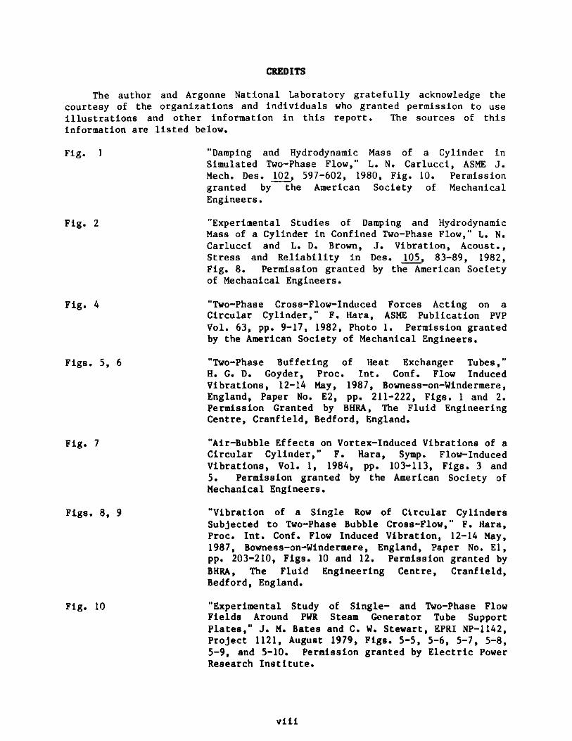
The author and Argonne National Laboratory gratefully acknowledge thecourtesy of the organizations and individuals who granted permission to useillustrations and other information in this report. The sources of thisinformation are listed below.
Fig. I "Damping and Hydrodynamic Mass of a Cylinder inSimulated Two-Phase Flow," L. N. Carlucci, ASME J.Mech. Des. 102, 597-602, 1980, Fig. 10. Permissiongranted by the American Society of MechanicalEngineers.
Fig. 2 "Experimental Studies of Damping and HydrodynamicMass of a Cylinder in Confined Two-Phase Flow," L. N.Carlucci and L. D. Brown, J. Vibration, Acoust.,Stress and Reliability in Des. 105, 83-89, 1982,Fig. 8. Permission granted by the American Societyof Mechanical Engineers.
Fig. 4 "Two-Phase Cross-Flow-Induced Forces Acting on aCircular Cylinder," F. Hara, ASME Publication PVPVol. 63, pp. 9-17, 1982, Photo 1. Permission grantedby the American Society of Mechanical Engineers.
Figs. 5, 6
Fig. 7
Figs. 8, 9
"Two-Phase Buffeting of Heat Exchanger Tubes,"H. G. D. Goyder, Proc. Int. Conf. Flow InducedVibrations, 12-14 May, 1987, Bowness-on-Windermere,England, Paper No. E2, pp. 211-222, Figs. 1 and 2.Permission Granted by BHRA, The Fluid EngineeringCentre, Cranfield, Bedford, England.
"Air-Bubble Effects on Vortex-Induced Vibrations of aCircular Cylinder," F. Hara, Symp. Flow-InducedVibrations, Vol. 1, 1984, pp. 103-113, Figs. 3 and5. Permission granted by the American Society ofMechanical Engineers.
"Vibration of a Single Row of Circular CylindersSubjected to Two-Phase Bubble Cross-Flow," F. Hara,Proc. Int. Conf. Flow Induced Vibration, 12-14 May,1987, Bowness-on-Windermere, England, Paper No. El,pp. 203-210, Figs. 10 and 12. Permission granted byBHRA, The Fluid Engineering Centre, Cranfield,Bedford, England.
"Experimental Study of Single- and Two-Phase FlowFields Around PWR Steam Generator Tube SupportPlates," J. M. Bates and C. W. Stewart, EPRI NP-1142,Project 1121, August 1979, Figs. 5-5, 5-6, 5-7, 5-8,5-9, and 5-10. Permission granted by Electric PowerResearch Institute.
Fig. 10
viii
Figs. 11, 12
Fig. 13
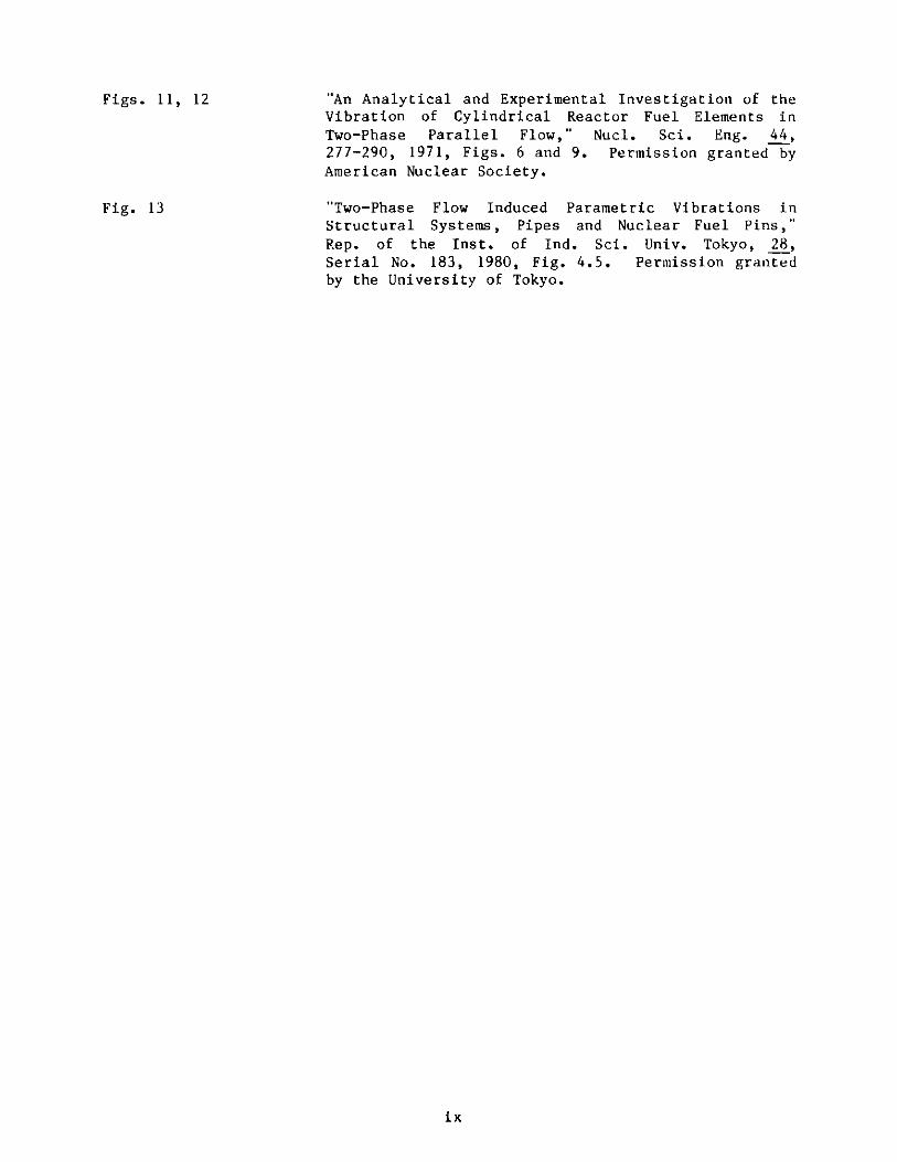
"An Analytical and Experimental Investigation of theVibration of Cylindrical Reactor Fuel Elements inTwo-Phase Parallel Flow," Nucl. Sci. Eng. 44,277-290, 1971, Figs. 6 and 9. Permission granted byAmerican Nuclear Society.
"Two-Phase Flow Induced Parametric Vibrations inStructural Systems, Pipes and Nuclear Fuel Pins,"Rep. of the Inst. of Ind. Sci. Univ. Tokyo, 28,Serial No. 183, 1980, Fig. 4.5. Permission grantedby the University of Tokyo.
ix
1
A REVIEW OF TWO-PHASE FLOW-INDUCED VIBRATION
S. S. Chen
ABSTRACT
Two-phase flow exists in many shell-and-tube heat exchangers
and power generation components. The flowing fluid is a source of
energy that can induce small-amplitude subcritical oscillations
and large-amplitude dynamic instabilities. In fact, many
practical system components have experienced excessive flow-
induced vibrations. To prevent unacceptable flow-induced
vibration, we must understand excitation mechanisms, develop
analytical and experimental techniques, and provide reliable
design guidelines. Thus, we are conducting a comprehensive
program to study structural vibration in components subjected to
two-phase flow. This report reviews the current understanding of
vibration of circular cylinders in quiescent fluid, crossflow, and
axial flow, with emphasis on excitation mechanisms, mathematical
models, and available experimental data. A unified theory is
presented for cylinders oscillating under different flow
conditions. Based on the theory, future research needs are
outlined.
I. INTRODUCTION
Two-phase flow exists in a wide variety of engineering systems, including
power, heat transfer, process, and transport systems. For example, in a
typical U-tube steam generator, the exit flow in the U-bend region is composed
of a water and steam mixture. A flowing two-phase fluid is a source of energy
that can induce and sustain structural vibration and instability. In fact,
two-phase flow can induce oscillations that are very similar to those of
single-phase flow and produce detrimental effects comparable to those of
single-phase flow.
Based on the direction of flow with respect to the major axis of
structural components, two-phase flow-induced vibration problems can be
divided into two groups: axial flow, in which the flow direction is parallel
to the structural axis; and crossflow, in which the flow direction is
perpendicular to the structural axis. Both axial-flow- and crossflow-induced
vibrations have been studied in past decades. A state-of-the-art review of
axial flow, with emphasis on circular rods, was reported by Shin (1978), and a
review of vibrations of circular cylinders in two-phase crossflow was reported
by Hara (1987b). This report reviews two-phase flow-induced vibrations for
crossflow as well as axial flow. The objective is to summarize the excitation
mechanisms, mathematical models, response characteristics, design
considerations, and future research needs.
2
Two models are frequently used for two-phase flow: the homogeneous flow
model and the separated flow model. The homogeneous flow model is used in
most cases for flow-induced vibration. If the cross sectional area of a
channel is A and the cross sectional area occupied by the gas and liquid
phases are Ag and At respectively, where the subscripts g and R indicate gas
and liquid respectively, then the void fraction a is given by
A
(1)
A1 - a = .
The mass flow rate is represented by W and will be the sum of the individual
phase flow rates Wg and W&. Thus, the mass quality (also referred to as mass
dryness fraction) X is defined as
Wg
g(2)
WR
1 -X -W + W *g
The mean velocity of an individual phase is denoted by U and the density by p;
thus
wU -g p A '
g g
U li , (3)
g x ( ..)IP )(I -C'jUt 1 X pg a
The mean flow velocity of the mixture U is given by
W + WU g t(4)
pA
3
where the mixture density is defined by
p = (1- ca)p, + apg . (5)
The Reynolds number is defined by
Re = pU/u (6)
where D is cylinder diameter and the dynamic viscosity u is determined by
McAdams correlation (Collier 1981):
I - + x .(7)
g "R
Based on the homogeneous two-phase flow model and theory of elasticity,
the dynamic fluid/structure interaction can be described by the same equation
as that for single-phase flow (Chen 1987):
[M]{Q} + [C]{Q} + [K]{Q} = {G} (8)
or
[M + Mf]{Q} + [Cs + Cf]{Q} + [Ks + Kf]{Q} = {G} (9)
where {Q} is the generalized structural displacement; [M] is the mass matrix,
including structural mass [Ms] and added mass [Mf]; [C] is the damping matrix,
including structural damping [Cs] and fluid damping [Cf]; [K] is the stiffness
matrix, including structural stiffness [Ks] and fluid stiffness [Kf]; and {G}represents the other excitation forces, including vortex shedding, turbulence,
and acoustic noises.
In general, M, C, K, and G are functions of Q, Q, and Q; therefore, a
complete solution is rather difficult to obtain. Fortunately, in most
practical situations, one can ignore all nonlinear terms that make M, C, K,
and G dependent on structural response. However, even in a linear case, it is
still not possible to obtain Mf, Cf, Kf, and G for most situations.
Once the two-phase fluid mass, damping, stiffness, and excitation are
known, Eq. (9) can be solved in a straightforward manner. The major task is
to obtain these fluid matrices and excitation forces for various flow
conditions. For small-amplitude oscillations, Mf and C are important for
4
structures oscillating in a quiescent fluid; in cross and axial flows, Mf, Cf,
Kf, and G are important. In this report, examination of the various
excitation mechanisms is based on the consideration of these fluid-force
matrices.
It should be noted that Eqs. (8) and (9) are approximate for structural
response in two-phase flow. All fluid effects are incorporated in Mf, Cf, Kf,
and G. In most cases, the equations are acceptable. However, in some
situations, they may not be adequate. Their applicability and limitations are
not well known at present. Modeling these fluid effects in two-phase flow and
establishing the range of applicability of the models are topics for future
research studies.
II. ADDED LASS AND DARNING
The added mass and damping for a circular cylinder oscillating in two-
phase flow has been studied based on the homogeneous model [Carlucci (1980),
Carlucci and Brown (1983), Hara and Kohgo (1982) and (1986), Pettigrew and
Tromp (1985)]. When such a circular cylinder has a displacement value u, the
fluid force g acting on it is given by the equation
8a 2u Ca
at at(10)at
where ma is the added mass and Cv is the fluid damping.
The added mass ma of a single cylinder in two-phase flow is given by
ma - CmMd , (11)
where Cm is the added-mass coefficient and Md is the displaced mass of
fluid. Experimental data for a single cylinder in an annular region indicate
that the added-mass coefficient for two-phase flow is the same as that for
single-phase flow. A summary of the results for single-phase flow has beenreported [Chen and Chung (1976)].
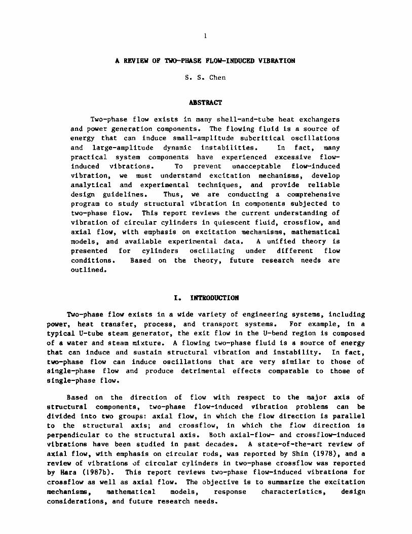
The added mass for two-phase flow is calculated from the homogeneous
model; i.e., it is equal to the displaced volume of fluid multiplied by the
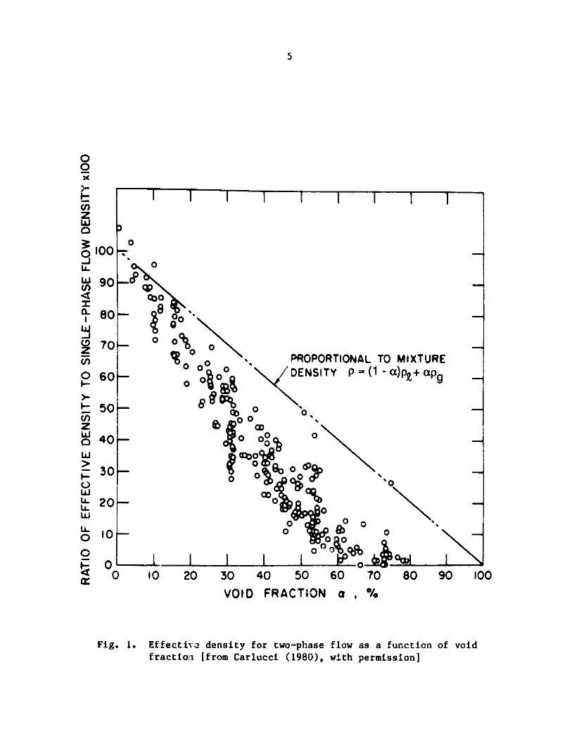
effective fluid density p. Theoretical and experimental studies have been
performed to quantify p. Typical experimental data are shown in Fig. 1
[Carlucci (1980)], where the ratio of the effective density to the single-
phase flow density pt is plotted as a function of void fraction a.
Several theories for the effective density have been summarized by
Schumann (1981):
5
I I I I I I I I
100
00
I-U)
0-JL
WCl)
9-
C,)
0
-
z
I-0
LLU.W
00
TO MIXTURE(1 - a)p + apg
0
%"
0cu
mmaw._ l1 L _ v -Ji~ -1 i
0 10 20 30 40 50 60 70 80 90 100
VOID FRACTION a ,
Fig. 1. Effective density for two-phase flow as a function of voidfraction [from Carlucci (1980), with permission]
0
CoO
-8
0 PROPORTIONAL0o0%00 DENSITY P=
00
0 0 0(COO0
0
00>
o O0
I-oI
90
80
70
60
50
40-
30
20
10
0
-
4-0-0
x
4mmmus
il
6
(a) p = (1 - a)pk + apg ,
(b) p = P&(1 - ac)/(2a + 1) , (12)
(c) p = pq(1 - a)(1 + 2a)/(1 + 4a - 2a2 )
The first of these equations represents the volumetrically averaged mixture
density; the other two are approximate virtual density formulas. The
theoretical results obtained from Eq. (12a) are presented in Fig. I to
facilitate comparison with the experimental data. According to Eq. (12a), for
a homogeneous two-phase mixture without slip, the effective density decreases
linearly with the void fraction a; at low values of a, it agrees well with the
experimental data. For larger a, the mixture density does not agree well with
the data; the effective density is less than the averaged density. The other
two theories represented in Eq. (12) correlate well with experimental data for
the middle range of a, but do not agree well with the data obtained when a is
close to 0 or 1.
There are several reasons for the discrepancies between the theory and
experimental data:
" Nonhomogeneity: The gas phase is not uniformly distributed in two-
phase flow. For example, in the bubbly flow regime, the gas bubbles may stay
close to the vibrating cylinder and reduce the effective density. In
addition, at void fractions of 60 to 80 percent, the flow regime is
essentially annular and the central portion of the flow passage is occupied
largely by the gas phase.
* Compressibility: Gas phase compressibility affects the inertia
effect.
* Slip Between the Phases: The two phases of fluid are not moving at
the same speed. Schumann's theory (1981) predicts that if there is slip
between phases, the effective density is lower than the mixture density. The
detailed mechanism(s) of how added mass causes deviation from the mixture
theory has not been established.
Although fluid damping in a two-phase flow was studied experimentally by
Carlucci and Brown (1983), Hara and Kohgo (1982, 1986), and Pettigrew et al.
(1985), the damping mechanisms operating in two-phase flow are not well
understood. Experimental studies have been performed for a single cylinder in
an annular region and for tube arrays. Mathematically, the viscous damping
coefficient Cv for two-phase flow is represented by
Cv = Cj+ Ct, (13)
7
where Cv is the damping coefficient attributed to the viscous effect and Ct is
the two-phase flow damping coefficient.
C, can be calculated on the basis of methods derived for single-phase
flow [Chen et al. (1976)]. However, when doing so, the effective fluid
density and viscosity should be used. The effective fluid density based on
the mixture theory is given in Eq. (5) and the mixture viscosity according to
McAdams is given in Eq. (7) [Collier (1981)]. There is no analytical
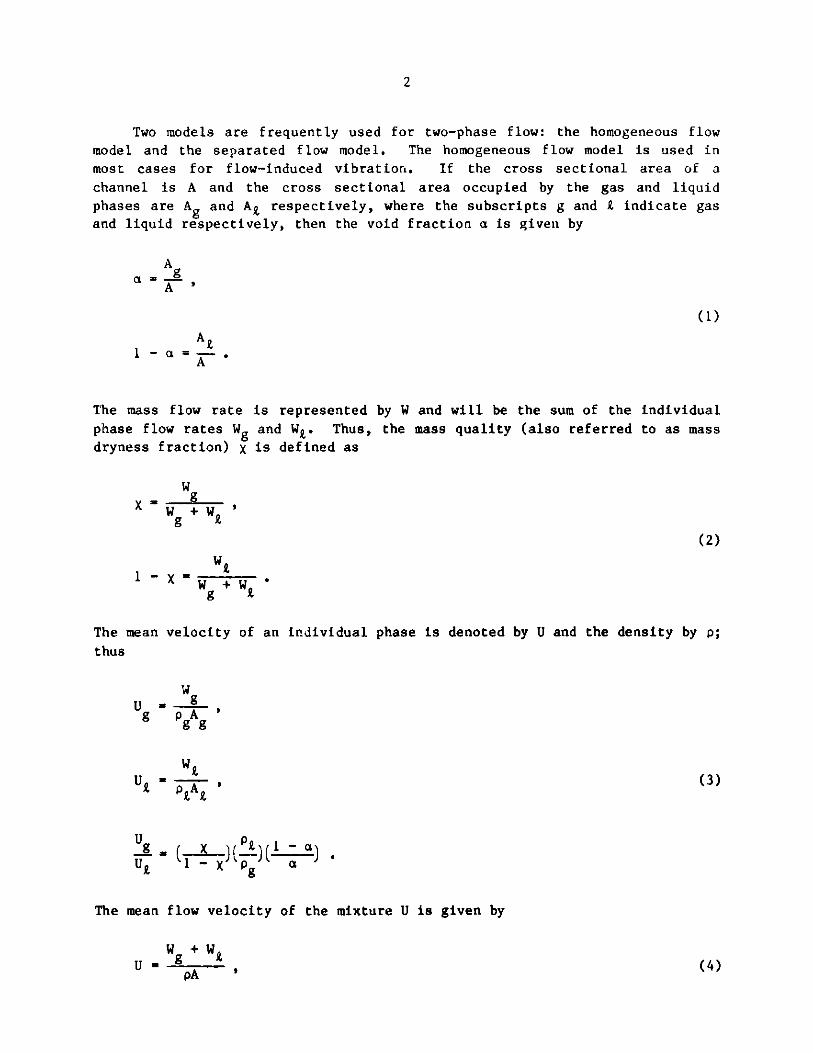
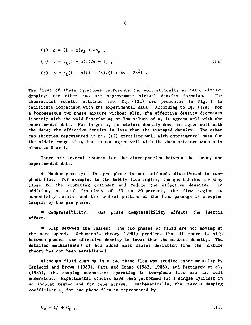
expression for Ct. The most complete experimental data, those of Carlucci and
Brown (1980), are given in Fig. 2. With Fig. 2, the two-phase damping
coefficient Ct can be calculated based on C,.
In addition to the mixture theory, a mathematical model was developed by
Hara and Kohgo (1986) to calculate the added mass and damping for a single
cylinder oscillating in two-phase flow. The bubble flow is modeled as gas
columns parallel to the vibrating cylinder. The gas columns are assumed to
have neither mass nor rigidity. Small-amplitude oscillations of the cylinder
and gas columns in fluid are then solved analytically. The added mass is
based on the ideal flow theory and the damping on linearized viscous flow
theory. Analytical and experimental results agree reasonably well.
The experimental technique for measuring the added mass and fluid-damping
in two-phase flow is the same as that for single-phase flow. The natural
frequencies and modal damping ratio in vacuum and in two-phase flow can be
measured separately; these values are represented by fv and ff, and v and
f. If the mass of the cylinder per unit length is m and the viscous damping
coefficient in vacuum is Cs, the added mass and fluid damping are given by
f2
ma = m( - 1 ,
f
and (14)
Sm +ma0.5C =C - 1v s Cv m
This technique has been used for a single cylinder [Chen and Chung (1976)].
Although a single added mass ma and damping coefficient Cv are sufficient
to characterize the effect of two-phase flow on a single cylinder, the
characterization of an array of N cylinders requires 4N2 added masses and 4N2
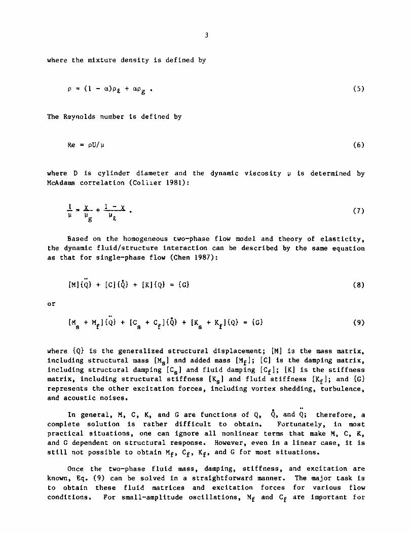
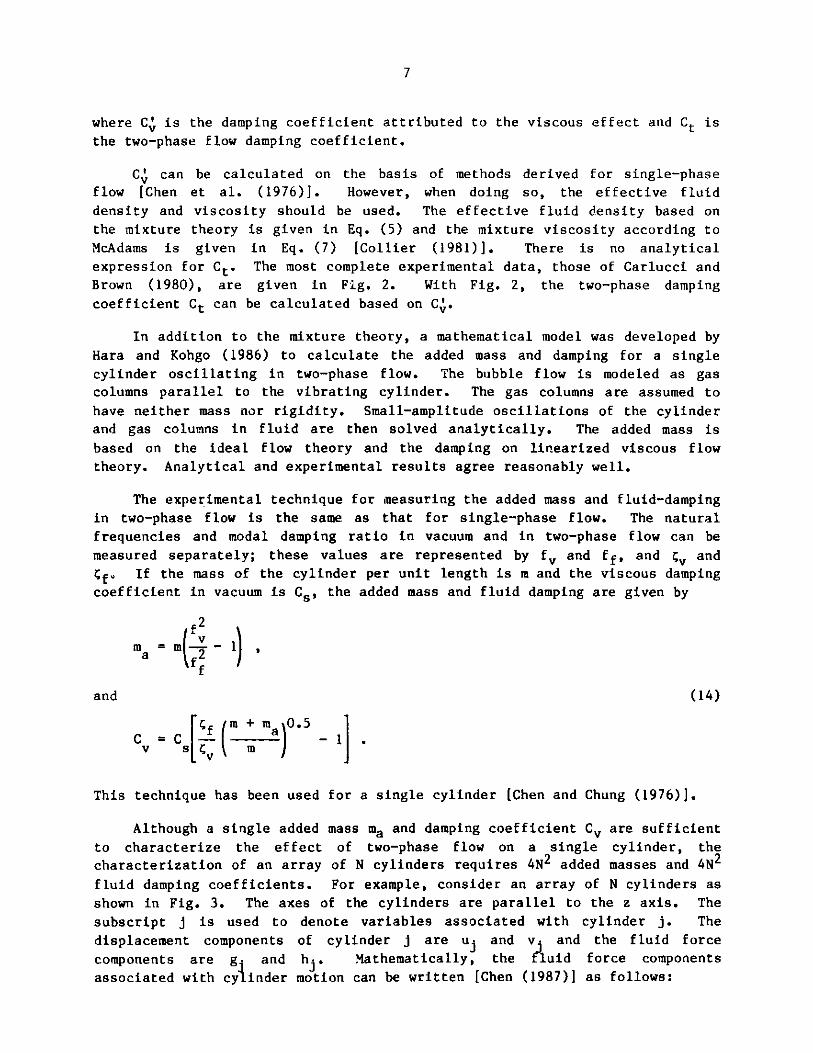
fluid damping coefficients. For example, consider an array of N cylinders as
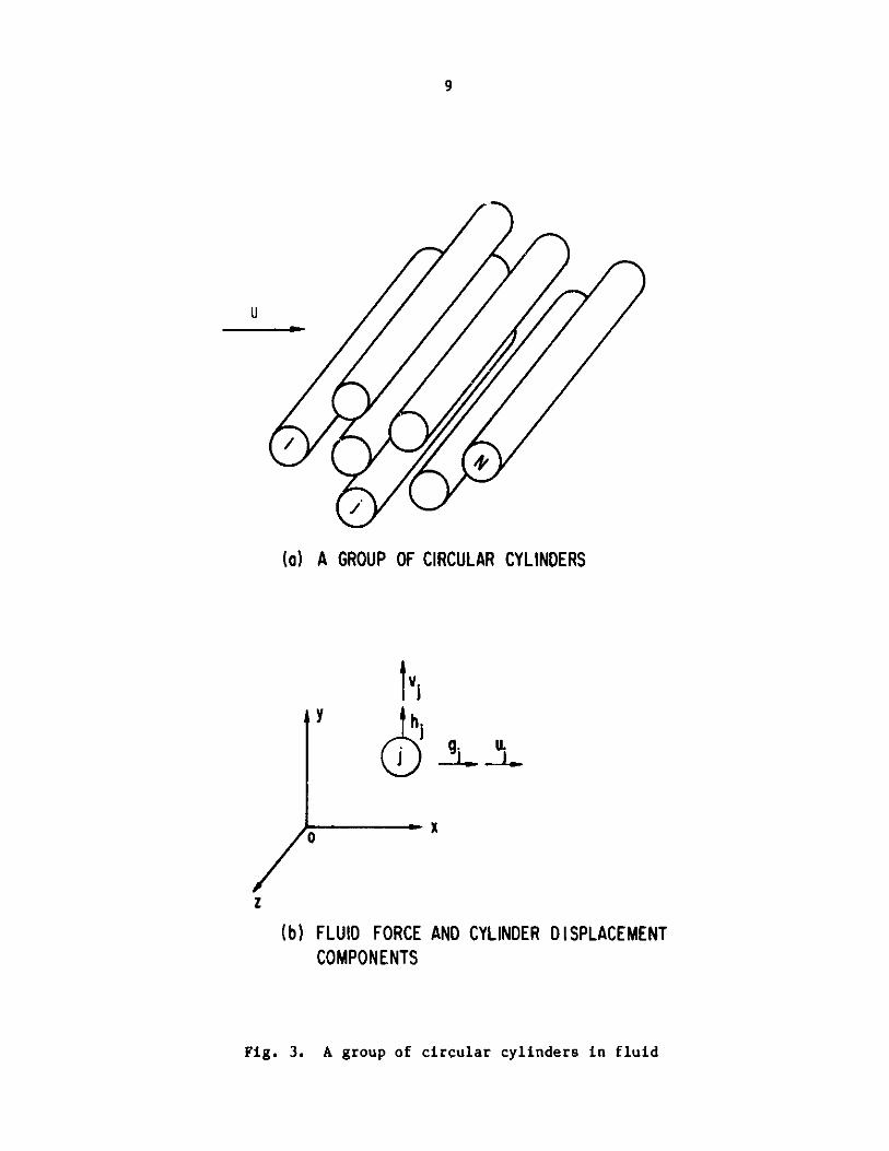
shown in Fig. 3. The axes of the cylinders are parallel to the z axis. The
subscript j is used to denote variables associated with cylinder j. The
displacement components of cylinder j are uj and v and the fluid force
components are g. and h.. Mathematically, the fluid force components
associated with cylinder motion can be written [Chen (1987)] as follows:
8
20 40
VOID FRACTION
60
a , %
80 100
Fig. 2. Two-phase flow damping coefficient [from Carlucci and Brown(1982), with permission]
7
6
0
I I I
0-
-- 0
O 0
0 O0
00
000o
0
5
4
3
2
01
0
9
U
(a) A GROUP OF CIRCULAR CYLINDERS
0x
(b) FLUID FORCE AND CYLINDER DISPLACEMENTCOMPONENTS
Fig. 3. A group of circular cylinders in fluid
10
N _ 32 vk - auk - a2 vk - avk
j k1 jk2at +jk at Jjk t2 jk at
and (15)
rN32 2auk+avkav
- kk=1 jk at2 jk at ) + kk at2 k at
where ajk ak'Tjk, and I.k are added mass matrices and ajk' "k tk, and
ajk are fluid-damping matrices. These results are the same as those for
single-phase flow. However, at this time, no analytical or experimental data
are available for two-phase flow. It is expected that the added-mass matrices
can be calculated on the basis of the potential flow theory, which has been
successfully used for single-phase flow, provided the effective fluid density
is used. Two-phase fluid damping remains a difficult parameter to predict ormeasure for the case of a cylinder array.
It is apparent that even for a single cylinder oscillating in two-phase
flow, the added mass and damping for different flow regimes are uiot well
understood. For a general case of cylinder arrays, there are no data
available for the added-mass and fluid-damping matrices. Although tube arrays
have been tested [e.g., Pettigrew et al. (1985)], no attempts have been made
to obtain the coupling effect. Thus, the coupling effect is a subject that
requires further study if one wishes to predict the response of a cylinder
array in two-phase flow.
Studies of added mass and damping have considered small oscillation
amplitudes. In single-phase flow, as long as the oscillation amplitude is
less than approximately 0.4 times the cylinder diameter, the linear theory
given in Eqs. (10) and (15) is applicable [Skop et al. (1976)]. Data for both
small- and large-amplitude oscillations in two-phase flow are lacking.
Once the added-mass and fluid-damping matrices are known, the response of
cylinders oscillating in a two-phase fluid can easily be calculated by using
Eq. (9). In a stationary fluid, the equation of motion is
[M + Mf]{Q} + [C + Cf ]{Q} + [K ]tQ} = {G} . (16)
In a single-phase fluid, Mf and Cf are symmetric matrices. In a two-phase
fluid, the characteristics of Mf and Cf are not known.
The interaction of two-phase flow with a vibrating cylinder is dependent
on the different flow regimes. In addition, cylinder oscillations may affect
phase distribution. The detailed physics of the interaction of cylinders and
two-phase flow is extremely complicated. Much more detailed studies,
11
including flow visualization, are needed to understand the interaction
process.
III. CROSSFLOW-INDUCED VIBRATION
Two-phase crossf low-induced vibration of circular cylinders has recently
been studied in several countries. As shown in Table 1, with the exception of
the tests by Axisa et al. (1984, 1985, 1986), all tests were performed for
air-water flow. The main objective of these studies has been to determine the
response of cylinder arrays in two-phase flow with the emphasis on identifying
the critical flow velocity. Several investigations have been conducted to
measure the fluid excitation forces: Hara (1982), for a single cylinder; and
Nakamura et al. (1982) and Taylor et al.. (1986), for cylinder arrays.
Void Fraction
Typically, the volume ratio S of the two phase flow is established by
metering the two types of fluid individually prior to mixing at the test
section. The assumption of a homogeneous mixture implies that the two phase
velocities are the same, in which case, the volume flow ratio (0) and the void
fraction (a) are the same. Several studies include measurements of void
fraction upstream or downstream of the bundle as well as inside the bundle.
Axisa et al. (1984) measured the void fraction at five locations along
the cylinder axis, but only at the upstream and downstream of the cylinder
array. The void fraction is determined as a function of mass quality X. Iageneral, the flow is not homogeneous across the test section. For a fixed
mass quality at low flow velocities, the local void fraction is smaller at the
center of the test section than at a location close to the wall. As flow
velocity increases, the void fraction is fairly uniform across the test
channel. At low flow velocity, the averaged spatial void fraction a is
smaller than the homogeneous void fraction a, but the difference between a and
a decreases with increasing flow velocity. Measurements of these values at
upstream and downstream of the tube bundle are similar and tests in air-water
and steam-water flows display similar trends.
Remy (1982) measured the void fraction between the fourth and fifth rows
of a square array with P/D = 1.44. Results show the very well-organized
characteristics of the flow. The void fraction exhibits a periodic variation
with the same period as the cylinder pitch. Furthermore, the variations
change with flow velocity. At low velocities, a maximum void fraction occurs
at the gap of the array. But at large flow velocities, there are two maxima,
one in the gap and the other in the wake of the cylinders. Although void
fraction within an array of cylinders varies, the averaged void fraction value
in a section is the same as the corresponding values upstream or downstream of
the bundles.
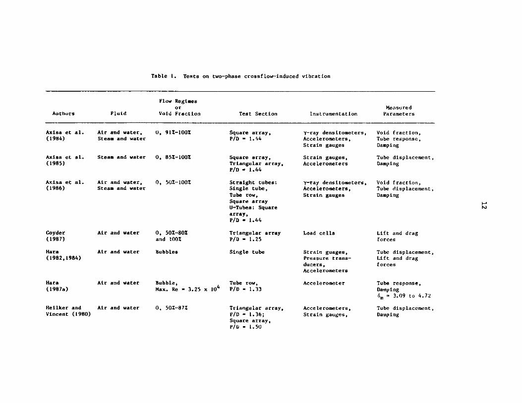
Table 1. Tests on two-phase crossf low-induced vibration
Flow Regimes
or MeasuredAuthors Fluid Void Fraction Test Section Instrumentation Parameters
Axisa et al.(1984)
Axisa et al.(1985)
Axisa et al.(1986)
Goyder(1987)
Hara(1982,1984)
Hara(1987a)
Heilker andVincent (1980)
Air and water,Steam and water
Steam and water
Air and water,Steam and water
Air and water
Air and water
Air and water
Air and water
0, 91%-100%
0, 85%-100%
0, 50%-100%
0, 50%-80Zand 100%
Bubbles
Bubble,Max. Re - 3.25 x 10⁴
0, 50%-87Z
Square array,P/D - 1.44
Square array,Triangular array,P/D - 1.44
Straight tubes:Single tube,Tube row,Square arrayU-Tubes: Squarearray,P/D - 1.44
Triangular arrayP/D - 1.25
Single tube
Tube row,P/D = 1.33
Triangular array,P/D - 1.36;Square array,P/li - 1.50
y-ray densitometers,Accelerometers,Strain gauges
Strain gauges,Accelerometers
y-ray densitometers,Accelerometers,Strain gauges
Load cells
Strain guages,Pressure trans-ducers,Accelerometers
Accelerometer
Accelerometers,Strain gauges,
Void fraction,Tube response,Damping
Tube displacement,Damping
Void fraction,Tube displacement,Damping
Lift and dragforces
Tube displacement,Lift and dragforces
Tube response,Damping6m = 3.09 to 4.72
Tube displacement,Damping
N-N
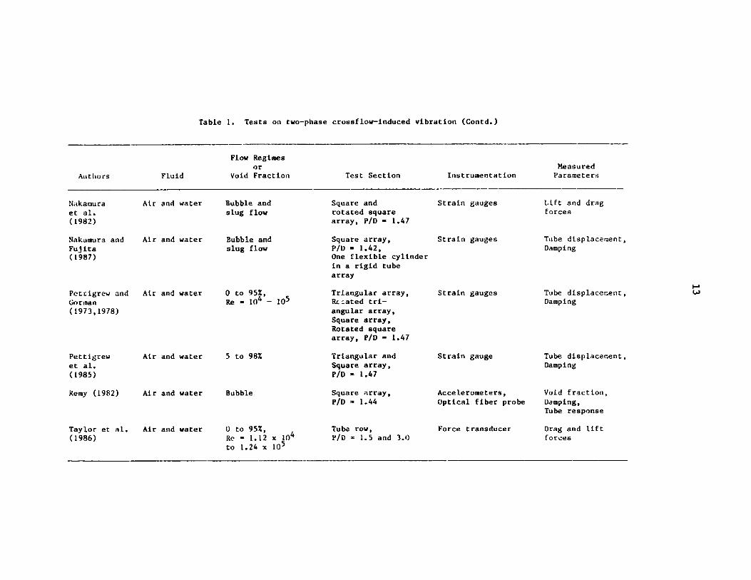
Table 1. Tests on two-phase crossflow-induced vibration (Contd.)
Flow Regimesor Measured
Authors Fluid Void Fraction Test Section Instrumentation Parameters
Nakamuraet al.(1982)
Nakamura andFujita(1987)
Petcigrew andGorman(1973,1978)
Pettigrewet al.(1985)
Remy (1982)
Taylor et al.(1986)
Air and water
Air and water
Air and water
Air and water
Air and water
Air and water
Bubble andslug flow
Bubble andslug flow
0 to 95%,Re - 1 - 1O5
5 to 98%
Bubble
o to 95%,Re a 1.12 x 10to 1.24 x 145
Square androtated squarearray, P/D - 1.47
Square array,P/D - 1.42,One flexible cylinderin a rigid tubearray
Triangular array,Rc--ated tri-angular array,Square array,Rotated squarearray, P/D - 1.47
Triangular andSquare array,P/D - 1.47
Square array,P/D = 1.44
Tube row,P/D = 1.5 and 3.0)
Strain gauges
Strain gauges
Strain gauges
Strain gauge
Accelerometers,Optical fiber probe
Force transducer
Lift and dragforces
Tube displacement,Damping
I-'Tube displacement, wDamping
Tube displacement,Damping
Void fraction,Damping,Tube response
Drag and liftforces
14
Added Mass and Damping
The added mass of an array of cylinders in crossflow has not been studied
in detail. Although this is true for both single- and two-phase flows, two-
phase flow data are especially limited. For practical purposes, there are no
complete sets of data for added-mass matrices of an array of cylinders. Theresults obtained when Remy (1982) tested a flexible cylinder in a rigid square
array can be used to calculate only the self-added mass a and Bj [see
Eq. (15)]. Other investigators performed tests on a flexible cylinder array
[Axisa et al. (1984) and Pettigrew et al. (1985)] but only the dominant
coupled modes were considered. Therefore, the individual elements of the
added-mass matrices are not considered by Axisa and Pettigrew. In order to
obtain the added-mass matrices, motion-dependent fluid forces associated with
the cylinder motion must be measured. No test results have been reported in
the literature.
If a cylinder is oscillating in two-ohase flow, damping can be associated
with different sources. Mathematically, it is convenient to separate the
damping into several components:
C =Cs + cf + Ct (17)
where C is the total damping ratio, is is the structural damping ratio, f is
the fluid viscous damping ratio for single-phase flow, and Ct is the two-
phase-flow damping ratio.
Fluid damping of single-phase flow consists of two parts: viscous
damping and flow-velocity-dependent damping. Calculation of the viscous
damping of two-phase flow, as discussed in Section II, can be based on the
same method as single-phase flow. The flow-velocity-dependent damping can be
calculated by the same method developed for a single cylinder in single-phase
flow [Chen (1987)]:
= C ( Md for drag direction,2 m a
=D -CD M+ for lift direction, (18)
2w2 km +mafD
where Md is the displaced mass of fluid, f is oscillation frequency, and CD is
the drag coefficient. Equation (18) is applicable for an isolated cylinder at
high reduced flow velocity.
15
Axisa et al. (1984) used Eq. (18) to obtain the two-phase flow damping
for a square array in air-water and steam-water two-phase flows. The results
agree reasonably well with those measured for a single cylinder in quiescent
fluid [Carlucci and Brown (1982)].
For an array of cylinders, the two-phase flow damping effect can also be
described by Eq. (15), where a'k, a'k, Tk, and k ere attributed to viscous
effects, flow-velocity-dependent components, and two-phase flow effects. The
details for a cylinder array in crossflow are not well understood at this
t ime.
Fluid Excitation Forces
Fluid excitation forces acting on circular cylinders were measured by
Hara (1982) for a single cylinder, and by Nakamura et al. (1982), Taylor et
al. (1986), and Goyder (1987) for an array of cylinders. In addition, fluid
forces have also been computed from cylinder responses subjected to crossflow
[Pettigrew and Gorman (1973)].
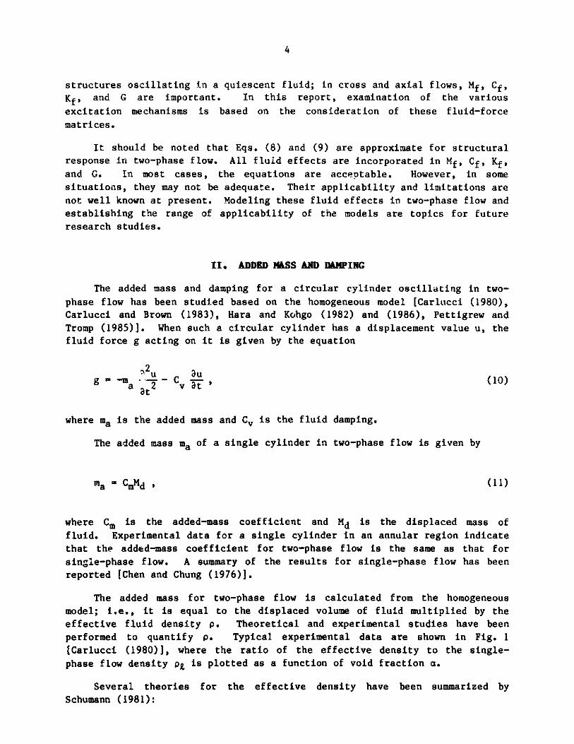
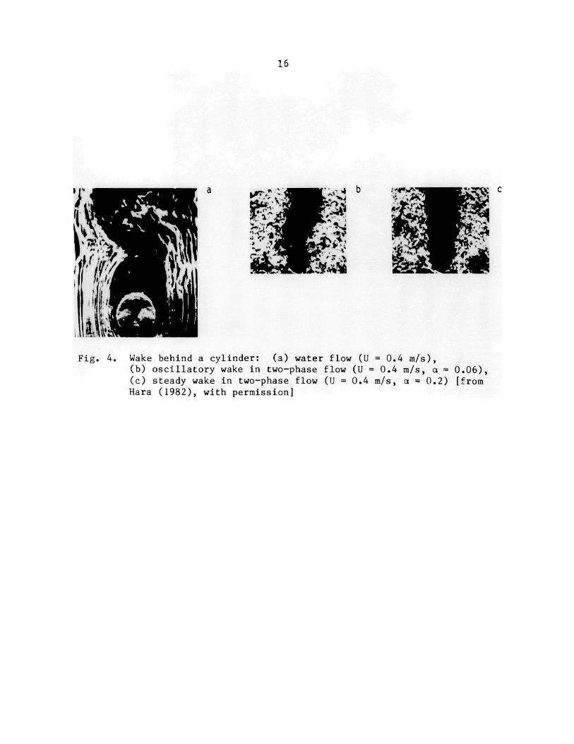
Hara measured the unsteady lift and drag forces and the pressure
fluctuation on a stationary cylinder immersed in a crossflow. The test,
performed in an air-water two-phase flow, shows that the existence of vortex
shedding for a single cylinder in crossflow depends on the void fraction. For
a less than about 10%, visualization of flow and measurement of fluid pressure
show the existence of vortex shedding in two-phase flow [see Fig. (4b)].
However, as a increases, the wavy motion of the wakes disappears [Fig. (4c)].
The characteristics of the pressure fluctuations and fluctuating drag and
lift forces also depend on the void fraction. For small a, where vortex
shedding exists, the pressure fluctuation and fluid forces vary insignifi-
cantly with a and are similar to those of single-phase flow. Furthermore the
lift force is narrow-banded and the drag force is less periodic. Although for
small a, the bubbles impinging on the cylinder may produce a larger force
compared with those for single-phase flow, the dominant frequency is that
attributed to vortex shedding because Karman vortex shedding remains the
dominant mechanism. On the contrary, when a is large, the motion of air
bubbles in the flow may be random and the impinging frequency may be
proportional to a and flow velocity. The lift and drag forces are of the same
magnitude and contain high-frequency components. For large a, vortex shedding
disappears and the drag and lift forces depend strongly on the void fraction.
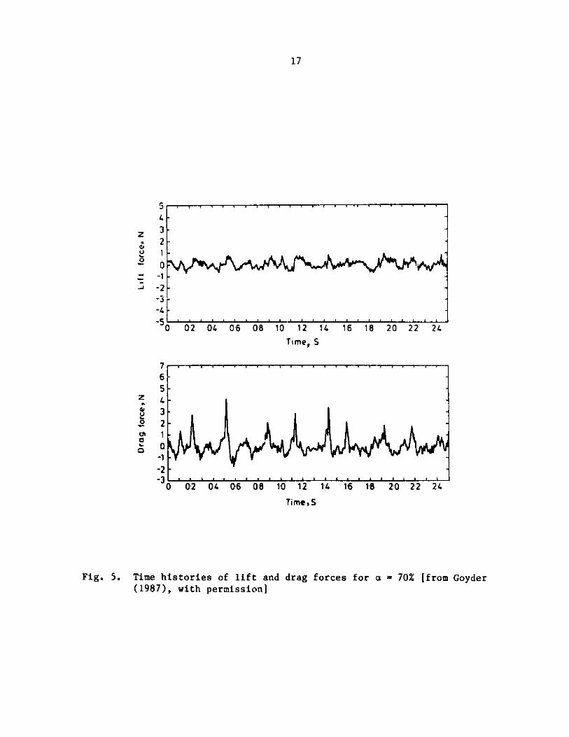
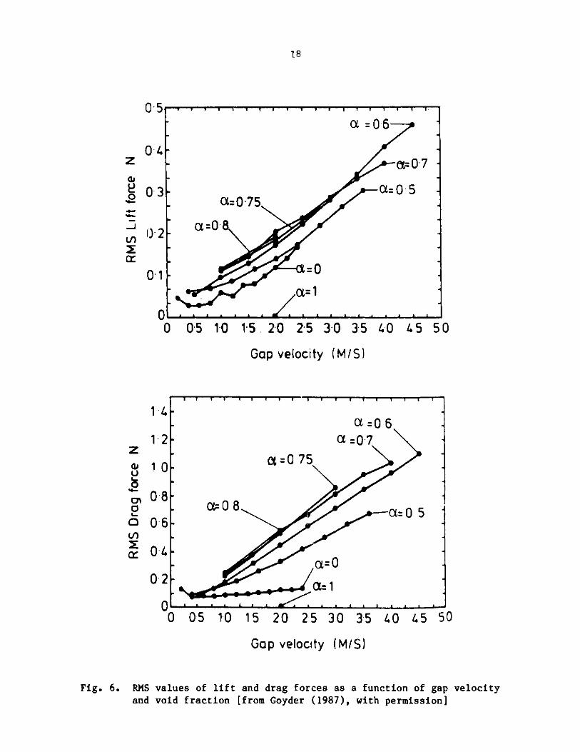
Goyder (1987) measured the fluctuating drag and lift forces of a
triangular array with a P/D of 1.25. Figures 5 and 6 show the time histories
for a = 70%, and rms values as a function of flow velocity, respectively.
Note that the peak amplitude of the drag force is much larger than that of the
lift force. Furthermore, whereas the drag force exhibits peaks and is
strongly asymmetric, the lift force is symmetric. The rms values of lift and
drag forces are approximately proportional to the velocity and are clearly
dependent on the void fraction a.
16
a y..'~b c
Fig. 4. Wake behind a cylinder: (a) water flow (U = 0.4 m/s),(b) oscillatory wake in two-phase flow (U = 0.4 m/s, a = 0.06),(c) steady wake in two-phase flow (U = 0.4 m/s, a = 0.2) [fromHara (1982), with permission]
17
z
U0
-J
S
432-
0-1
-2-3-4-5
C
7.6
z4,
0
01
0
4321
0-1-2
0-2 0.4 06 08 10 12 1. 16 18 20 22 24Time, S
0 02 04 0-6 08 10 12 1. 16 18 20 22 2.
Time, S
Fig. 5. Time histories of lift and drag forces for a = 70% [from Goyder(1987), with permission)
.2
a I I- I-- I 1-
18
95J'
z
L)0
~r.
I
0'4
0-3F'
) 2
01
00 05 10 15. 20 25 30 35 40 45 50
Gap velocity (M/S)
z
0
0
QoI
14l
12
10
08
06
04
0-2
0 05 10 15 20 25 30 35 40 45 50
Gap velocity (M/S)
Fig. 6. RMS values of lift and drag forces as a function of gap velocityand void fraction [from Goyder (1987), with permission]
0
I~ -I I I I I I I ---T- -- I T I-- I I I I T I
a=06ac=07
a=0 75
a=0 5
a=1
I l l A 1 1 1 1 L 1 1 1 1 1 1 1 1 l l 1
1 11 a i 1 I _L 1 I 1
a = 0.6
cc=0=7
a=0.-5
a=0.75
a=0.
-=0
a-_1
I I I I I 1 1
19
Nakamura et al. (1982) tried to characterize the excitation force and
found that the characteristics of the forces depend on the flow regime. Thecross spectral density of the excitation force 4gg(z,z',w) is considered to be
the product of R1(z,w), determined by the position, and R2(z - z',w), the
component that gives the correlation of two points:
0gg(z,z',w) = R1(z,w)R2 (z - z',w) . (19)
R1(z,w) is determined by the strength of the two-phase fluid force at each
point. R2(z - z',w) is a function of distance. If the shapes of the power
spectrum of excitation force are spatially homogeneous, R1 (z,w) can be written
R1(z,w) = RI(z)Ri(w) , (20)
where R'(w) is normalized such that
2n J R"(w)dw = 1 . (21)0
Nakamura et al. (1982) assumed that R(z - z',w) is 1 and Rj(z) is a
constant. BaseJ on these assumptions, the following characteristics are
noted.
* Excitation forces in two-phase flow can be classified according to
flow pattern. In slug flow, liquid slugs flow intermittently at arate of several times a second. The exciting force is mainly due to
the bumping of liquid slugs against the cylinder, resulting in a large
drag force and a lift force about 40% of the drag force. In bubble
flow, the excitation force is reduced and its magnitude is equal to
about 30 to 50% of the slug flow.
* The power spectra of excitation forces for bubble and slug flows are
similar. In both cases, the frequency components at low frequency are
high (1-10 Hz) and decrease with frequency. Cylinder location and
arrangement do not have a significant effect on the power spectra.
" The rms drag and lift forces in a slug flow are independent of the
superficial gas velocity and are proportional to the superficial
liquid velocity. (Superficial-phase velocity is defined as the
velocity the phase would have if it flowed alone through the flow
channel). Taylor et al. (1986) obtained similar results for a tuberow with a P/D of 1.5 and 3.0. For a from 20 to 80%, the spectra show
a dominance of the drag force over the lift force. For low values ofa, the spectra are almost identical to those of single-phase flow.
20
In single-phase flow, the power spectral density of the fluid excitation
force can be normalized by the dynamic pressure head multiplied by the
cylinder length 9 and cylinder diameter D, i.e., as shown by Taylor et al.
(1986) and Chen and Jendrzejczyk (1986):
(w)e (s) = 1 2 ] (22)
pU2DZJ
However, for two-phase flow, a nondimensional group of parameters has not been
found to collapse the two-phase data.
In spite of the difficulty of normalizing the spectra, Pettigrew and
Gorman (1978) use Eq. (22) to estimate the spectra of the fluid force
coefficients in practical applications. The coefficients are inferred from
tube response to two-phase flow.
Structural Response
The vibration of cylinders in two-phase flow is similar to that in
single-phase flow. Oscillations can be divided into three groups: vortex-
excited oscillations, subcritical oscillations, and dynamic instability.
The response of a single cylinder in two-phase flow depends on the void
fraction. Typical responses of a cylinder in the drag and lift direction
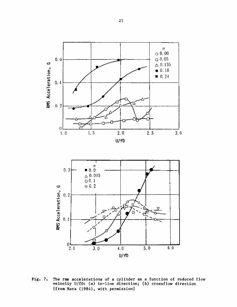
obtained during a detailed study by Hara (1984) are given in Fig. 7. Single-phase flow can induce large in-line oscillations when U/fD ~ 2.1. When the
void fraction is 5%, the response amplitude is significantly reduced for Ur
from 0.5 to 2.5; in particular, at Ur = 2.1, the amplitude is reduced to about
25% of that in water flow. As the void fraction increases, the response
amplitude increases. When a is large, the oscillation amplitude is very large
compared with that in water flow (a = 0).
The response in the crossflow direction of a single cylinder is different
from the in-line response. For a S 20%, vibration amplitude increases almost
linearly with Ur up to Ur = 4.5. For Ur > 4.5, vibration amplitude decreases
for a < 10% and is almost a constant value for larger a, e.g., a = 20%.
Figure 7 shows that for Ur > 4.5 the oscillation amplitude is drastically
reduced by injecting a certain amount of air bubbles into the flow. For
Ur 4. 45, however, the two-phase flow-induced vibration is much stronger than
that excited by vortex shedding in water flow.
Based on data of Hara (1984), it may be concluded that the excitation
mechanisms for a single cylinder are the buffeting forces due to the random
motion of air bubbles in the flow and vortex shedding that generates a narrow-
banded force on the cylinder at low a. Furthermore, a small amount of air
bubbles reduces the in-line and crossflow lock-in resonances and a large
amount of air bubbles excites large cylinder oscillations.
21
C0
S.,rV
0. 6
0. 4
0. 2
1.0 1.5 2. 0 2. 5 3. 0
U/f D
0. 3
CD
c 0. 2
0 .a)U
"~ 0.1
cc
02. 0 3. 0 4.0 5. 0 6. 0
U/fD
Fig. 7. The rms accelerations of a cylinder as a function of reduced flowvelocity U/fD: (a) in-line direction; (b) crossflow direction[from Hara (1984), with permission]
no 0.00
- 0 0.01A 0.135* 0.18
0. 24
- 0. 0
o 0. 015
S0. 2
Q-
I- -
()
22
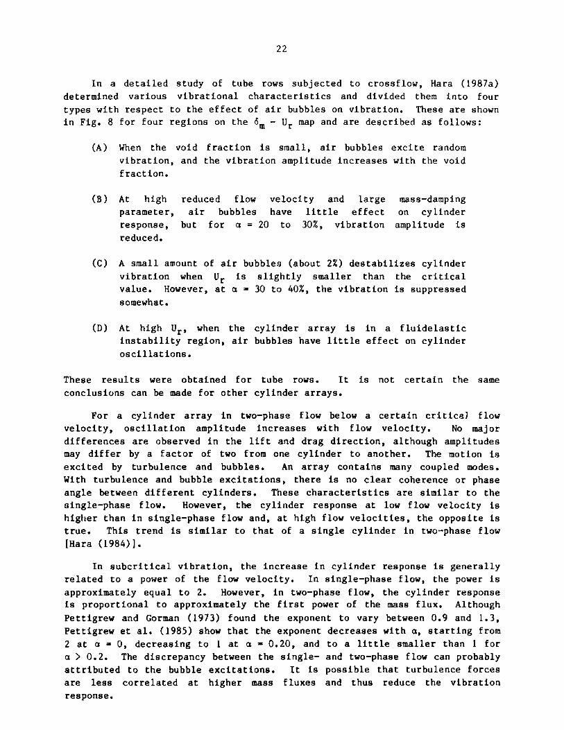
In a detailed study of tube rows subjected to crossflow, Hara (1987a)
determined various vibrational characteristics and divided them into four
types with respect to the effect of air bubbles on vibration. These are shownin Fig. 8 for four regions on the 6m - Ur map and are described as follows:
(A) When the void fraction is small, air bubbles excite random
vibration, and the vibration amplitude increases with the void
fraction.
(B) At high reduced flow velocity and large mass-damping
parameter, air bubbles have little effect on cylinder
response, but for a = 20 to 30%, vibration amplitude is
reduced.
(C) A small amount of air bubbles (about 2%) destabilizes cylinder
vibration when Ur is slightly smaller than the critical
value. However, at a - 30 to 40%, the vibration is suppressed
somewhat.
(D) At high Ur, when the cylinder array is in a fluidelastic
instability region, air bubbles have little effect on cylinder
oscillations.
These results were obtained for tube rows. It is not certain the same
conclusions can be made for other cylinder arrays.
For a cylinder array in two-phase flow below a certain critical flow
velocity, oscillation amplitude increases with flow velocity. No major
differences are observed in the lift and drag direction, although amplitudes
may differ by a factor of two from one cylinder to another. The motion is
excited by turbulence and bubbles. An array contains many coupled modes.
With turbulence and bubble excitations, there is no clear coherence or phase
angle between different cylinders. These characteristics are similar to the
single-phase flow. However, the cylinder response at low flow velocity is
higher than in single-phase flow and, at high flow velocities, the opposite is
true. This trend is similar to that of a single cylinder in two-phase flow
[Hara (1984)].
In subcritical vibration, the increase in cylinder response is generally
related to a power of the flow velocity. In single-phase flow, the power is
approximately equal to 2. However, in two-phase flow, the cylinder response
is proportional to approximately the first power of the mass flux. Although
Pettigrew and Gorman (1973) found the exponent to vary between 0.9 and 1.3,
Pettigrew et al. (1985) show that the exponent decreases with a, starting from
2 at a - 0, decreasing to 1 at a - 0.20, and to a little smaller than 1 for
a > 0.2. The discrepancy between the single- and two-phase flow can probably
attributed to the bubble excitations. It is possible that turbulence forces
are less correlated at higher mass fluxes and thus reduce the vibration
response.
23
B
12 -B-
1 0-D
0
- D
CU
6 --
4 -r.,.-'A-
2
0 1 2 3 4 5Mass Damping Parameter am
Fig. 8. Vibration characteristics (a - vibration amplitude, a = voidfraction) [from Hara (1987a), with permission]
24
In two-phase flow, the vibration within an array and the vibration of
different arrays are also not the same as in single-phase flow. For example,
Pettigrew and Gorman (1973) found that in two-phase flow the upstream tubes
vibrate most and for a fixed P/D and various classical tube layouts, the
rotated square arrays vibrate most, the rotated triangle and square arrays
vibrate least, and the triangular arrays vibrate moderately. In addition, the
preferred direction of motion is in the flow direction.
A cylinder array in two-phase flow will become unstable when the flow
velocity is increased to a threshold value. Axisa et al. (1984) found that
there is a fairly clearly defined critical flow velocity below which cylinder
displacement is increasing with flow velocity raised to a certain power.
Above the critical flow velocity the coherence and phase angle between various
pairs of cylinders are well defined. In contrast, Pettigrew et al. (1985)
found that the instability thresholds are well defined at lower and higher abut less well defined at the intermediate values of void fractions. In any
case, both groups use the following stability criteria to correlate their
data:
0.5
f-= K( 2ncm) , (23)
pD
where U and p are given in Eqs. (4) and (5). Pettigrew et al. (1985) and
Axisa et al. (1985), respectively, determined that K is equal to 4.0 and 7.2
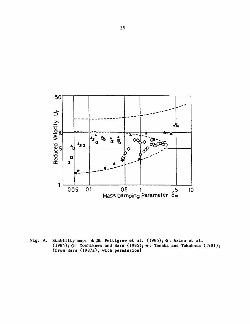
Hara (1987a) summarizes the published data for tube arrays as well as his
own data in Fig. 9, where the broken lines are the theoretical results
obtained by Chen and Jendrzejczyk (1983) in water flow. When the void
fraction is small, the critical flow velocity increases with the void
fraction. The mass-damping parameter also increases with the void fraction
owing to the reduction in two-phase flow density defined by the component
(1 - a)pR. For a relatively large mass-damping parameter (6m = 3 to 5), the
critical flow velocity in two-phase flow is different from that for water
flow.
In liquid flow, there exist two critical flow velocities: intrinsic
critical flow velocity and excited critical flow velocity. The former is
larger than the latter by as much as 30% [Chen and Jendrzejczyk (1987) and
Hara (1987a)]. In two-phase flow, no such hysteresis is observed.
Mathematical Models for Two-Phase Crossf low-Induced Vibration
The analysis of an array of cylinders oscillating in two-phase flow has
been performed based on the incorporation in the beam equation of some fluid
effects [Pettigrew and Gorman (1973) and Axisa et al. (1984)]. No analysis
has been made for coupled modes of multiple cylinders. A model based on
coupled modes for single-phase flow is applied here to two-phase flow.
25
L.
D
1
F F
0.05 0.1 1
Mass Damping Parameter s; 10
Fig. 9. Stability map: A,M: Pettigrew et al. (1985); 0: Axisa et al.(1984); p: Yoshikawa and Hara (1985); *: Tanaka and Takahara (1981);[from Hara (1987a), with permission]
f o-
~~--ai -
ci_ -- -__- _ _-
I
I A%
r
r
.60 .00 ago dob
dop dow SLID r
I
0 5 97
26
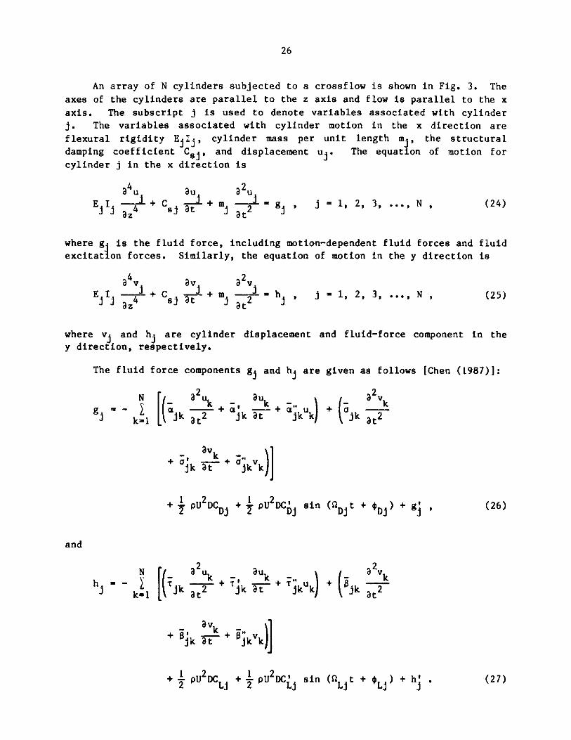
An array of N cylinders subjected to a crossf low is shown in Fig. 3. Theaxes of the cylinders are parallel to the z axis and flow is parallel to the x
axis. The subscript j is used to denote variables associated with cylinderj. The variables associated with cylinder motion in the x direction are
flexural rigidity Ej j, cylinder mass per unit length mj, the structuraldamping coefficient Csj, and displacement uj . The equation of motion forcylinder j in the x direction is
8 4u
E I$ az4 + C 5au
at3 2 u
+ m 2 g j = 1, 2, 3, ... , Nj at2
where g is the fluid force, including motion-dependent fluid forces and fluidexcitation forces. Similarly, the equation of motion in the y direction is
a4v
ELI z$+
av a2 vC i+m -1 - , i-l,2,3,..., N,8 j F i'at 2 h1 > (25)
where vi and hj are cylinder displacement and fluid-force component in they direction, respectively.
The fluid force components gj and h are given as follows [Chen (1987)]:
at j
2+ k
auk
+ jku
a2 v
+ jik
+ vk + kk
+ PU2 Dj + 1 PU2DC sin( (1 t + D)+g2WP D~ 2 Di Di Di g
Nh - -
k=ijk
a 2u auk
at 2 jk+at jkk + (jk
a v
ate
a v
+ jk at + kvk
+1 pU2 DLj + PU2D sin tLj t+ +)+ h'.L
(24)
N k[i
g -- k=1 jk
and
(26)
(27)
27
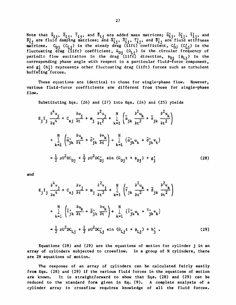
Note that a a, ijij, and i jare added mass matrices; ai j, i j, Ti , andBi are fluid damping matrices; and , , T ,,and i are fluid stiffness
matrices. CDj (CL ) is the steady drag (lift) coefficient, CJ (C) is the
fluctuating drag (lift) coefficient, %D (L) is the circular frequency ofperiodic flow excitation in the drag (lift) direction, *Dj (0Lj) is the
corresponding phase angle with respect to a particular fluid-force component,
and g3 (h3) represents other fluctuating drag (lift) forces such as turbulent
buffeting forces.
These equations are identical to those for single-phase flow. However,
various fluid-force coefficients are different from those for single-phase
flow.
Substituting Eqs. (26) and (27) into Eqs. (24) and (25) yields
a 4 u au a2u N ( a2u -a2v
E az4 + Csj at + m at2 k=l ajkjk at2 k
Nauk avk Nk= 1 jka + ka + kl jkuk + jkvk
=12pU 2 DC + pU2 DC' sin ( Djt + $Dj) + g! (28)
and
a4v av a 2 v N a2u 2vE Id +2 4 +C + m+ kt2 k 1 jk at2 + tjk
N auk - avk N
+ Tjk at + %k at- + k (Tkuk + Jkvk)k 1 21k1
=2pU2DCLj + pU2DCLI sin (QLjt + $Lj) + h . (29)
Equations (28) and (29) are the equations of motion for cylinder j in an
array of cylinders subjected to crossflow. In a group of N cylinders, there
are 2N equations of motion.
The response of an array of cylinders can be calculated fairly easily
from Eqs. (28) and (29) if the various fluid forces in the equations of motion
are known. It is straightforward to show that Eqs. (28) and (29) can be
reduced to the standard form given in Eq. (9). A complete analysis of a
cylinder array in crossflow requires knowledge of all the fluid forces.
28
Unfortunately, at this time, complete information is not available for
specific cylinder arrays. This suggests that, for practical applications,
simplifications or assumptions must be made to solve the problem.
Cylinders Immersed in Fluidized Beds
So far discussions have been limited to two-phase flow consisting of twofluid components. Another important problem of two-phase crossflow-induced
vibration is the fluidized bed. Heat is extracted from fluidized bed reactors
by tube arrays immersed in the bed.
Whereas heat transfer in fluidized beds has received considerable
attention, very little work has been reported on fluid forces and associated
tube vibration and wear. The limited number of -udies reported in the openliterature have all been published subsequent :o 1980 [Kennedy et al. (1981),Turner and Irving (1982), Hosny and Grace (1983, 1984), and Grace and Hosny(1985)]. These investigations are useful because they provide insights into
the characteristics of fluid forces acting on tube arrays in fluidized beds.Some of the essential characteristics determined from these studies can be
summarized as follows:
Flow Regimes
In a fixed bed, up to the condition of incipient fluidization, the tubes
are subjected to an effective buoyancy force only. As the flow velocity
increases to the bubbling regime, the tubes are subjected to a drag force in
the downstream direction as the bubble approaches and to a force in the
upstream direction as the bubble leaves the tube. Once the flow velocity isincreased to the point where the flow is in the turbulent regime, the
magnitude of the fluid force is reduced. The bubbling regime is of particular
interest because the fluid force encountered has a maximum magnitude which is
difficult to quantify.
Tube Array vs. Single Tube
Fluid forces depend on tube arrangement and spacing. Fluid forces acting
on a tube array are smaller than those acting on the same tube in isolation.
In general, the fluid force is largest on the upstream tube and smallest on
the downstream tube. In addition, the peak frequency of the fluid forces for
tubes in the middle of a tube array is higher because bubble splitting by thetube array results in a greater frequency of bubble-induced pulses. In a tube
array, vertical components are also substantially larger than the
corresponding horizontal components.
Ef fectsof Systen Parameters
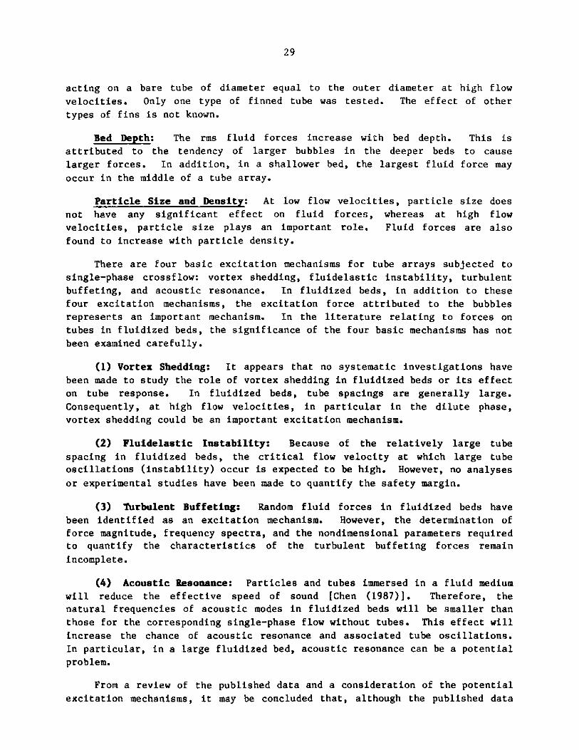
Tube Shape: Finned and unfinned tubes were tested by Grace and Hosny
(1985). The rms fluid force acting on a finned tube approaches the force
acting on a bare tube of the same volume at low flow velocities and the force
29
acting on a bare tube of diameter equal to the outer diameter at high flow
velocities. Only one type of finned tube was tested. The effect of other
types of fins is not known.
Bed Depth: The rms fluid forces increase with bed depth. This is
attributed to the tendency of larger bubbles in the deeper beds to cause
larger forces. In addition, in a shallower bed, the largest fluid force may
occur in the middle of a tube array.
Particle Size and Density: At low flow velocities, particle size does
not have any significant effect on fluid forces, whereas at high flow
velocities, particle size plays an important role. Fluid forces are also
found to increase with particle density.
There are four basic excitation mechanisms for tube arrays subjected to
single-phase crossflow: vortex shedding, fluidelastic instability, turbulent
buffeting, and acoustic resonance. In fluidized beds, in addition to these
four excitation mechanisms, the excitation force attributed to the bubbles
represents an important mechanism. In the literature relating to forces on
tubes in fluidized beds, the significance of the four basic mechanisms has not
been examined carefully.
(1) Vortex Shedding: It appears that no systematic investigations have
been made to study the role of vortex shedding in fluidized beds or its effect
on tube response. In fluidized beds, tube spacings are generally large.
Consequently, at high flow velocities, in particular in the dilute phase,
vortex shedding could be an important excitation mechanism.
(2) Fluidelastic Instability: Because of the relatively large tube
spacing in fluidized beds, the critical flow velocity at which large tube
oscillations (instability) occur is expected to be high. However, no analyses
or experimental studies have been made to quantify the safety margin.
(3) Turbulent Buffeting: Random fluid forces in fluidized beds have
been identified as an excitation mechanism. However, the determination of
force magnitude, frequency spectra, and the nondimensional parameters requiredto quantify the characteristics of the turbulent buffeting forces remain
incomplete.
(4) Acoustic Resonance: Particles and tubes immersed in a fluid medium
will reduce the effective speed of sound [Chen (1987)]. Therefore, thenatural frequencies of acoustic modes in fluidized beds will be smaller than
those for the corresponding single-phase flow without tubes. This effect will
increase the chance of acoustic resonance and associated tube oscillations.
In particular, in a large fluidized bed, acoustic resonance can be a potential
problem.
From a review of the published data and a consideration of the potential
excitation mechanisms, it may be concluded that, although the published data
30
provide insights into the dynamic characteristics of the fluid forces acting
on tube arrays in fluidized beds, a systematic study is lacking and urgently
needed.
IV. AXIAL-FLOW-INDUCED VIBRATION
Axial-flow-induced vibration problems can be divided into those
attributable to internal flow and those attributable to external flow. Two-
phase flow in pipes is a typical internal flow problem; nuclear fuel pins
subjected to axial two-phase flow is a typical external flow problem. Both
internal and external flow problems have been studied in the last 15 years.
Internal Flow
Pipes conveying a two-phase fluid have been studied by Hara (1973), Hara
et al. (1974), Hara (1977), Hara (1980), Yih and Griffith (1970), and
Pettigrew and Paidoussis (1975). The dynamic responses considered include
subcritical vibration, parametric resonance, and flutter.
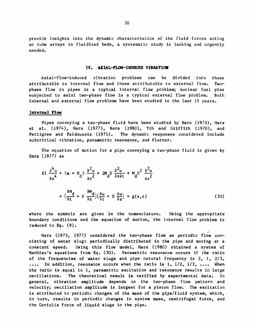
The equation of motion for a pipe conveying a two-phase fluid is given by
Hara (1977) as
EIa + (m + M ) + 2dU + M U2 uz at z
+ (y+- U )( L-+ U-) = g(z,t) (30)
where the symbols are given in the nomenclature. Using the appropriate
boundary conditions and the equation of motion, the internal flow problem is
reduced to Eq. (9).
Hara (1973, 1977) considered the two-phase flow as periodic flow con-
sisting of water slugs periodically distributed in the pipe and moving at a
constant speed. Using this flow model, Hara (1980) obtained a system of
Mathieu's equations from Eq. (30). Parametric resonance occurs if the ratio
of the frequencies of water slugs and pipe natural frequency is 2, 1, 2/3,
.... In addition, resonance occurs when the ratio is 1, 1/2, 1/3, .... When
the ratio is equal to 1, parametric excitation and resonance results in large
oscillations. The theoretical result is verified by experimental data. In
general, vibration amplitude depends on the two-phase flow pattern and
velocity; oscillation amplitude is largest for a piston flow. The excitation
is attributed to periodic changes of the mass of the pipe/fluid system, which,
in turn, results in periodic changes in system mass, centrifugal force, and
the Coriolis force of liquid slugs in the pipe.
31
Pettigrew and Paidoussis (1975) performed tests on a cylinder immersed in
an annulus two-phase flow. In the subcritical flow velocity range, the
vibration response is fairly severe and broadbanded. The motion is excited by
random turbulence associated with two-phase flow.
External Flow
Studies of cylinders submerged in two-phase flow are focused on nuclear
fuel pins. Investigations have been reported for a single cylinder by Gorman
(1971), Harris and Holland (1971), Harris and Ledwidge (1971), Harris and
Holland (1973), Hara (1975a) and (1975b), Hara and Yamashita (1978), and Hara
(1980); for multiple cylinders by Winsbury and Ledwidge (1973), Dallavalle et
al. (1973), and Gorman (1975); and for simulated fuel bundles by Cedolin et
al. (1971), and Hayes (1982). A survey of this problem was reported by Shin
(1978).
The equation of motion of a single cylinder in axial two-phase flow is
still not well. established. In the past, the Bernoulli-Euler beam equation of
motion was used [Hara (1975a) and Gorman (1975)] and the fluid-force
components associated with two-phase flow, including added mass, fluid
damping, and fluid stiffness, were not accounted for consistently. Using the
model for single-phase flow, Shin (1978) modified the Chen and Wambsganss
(1972) equation of motion for single-phase flow for application to two-phase
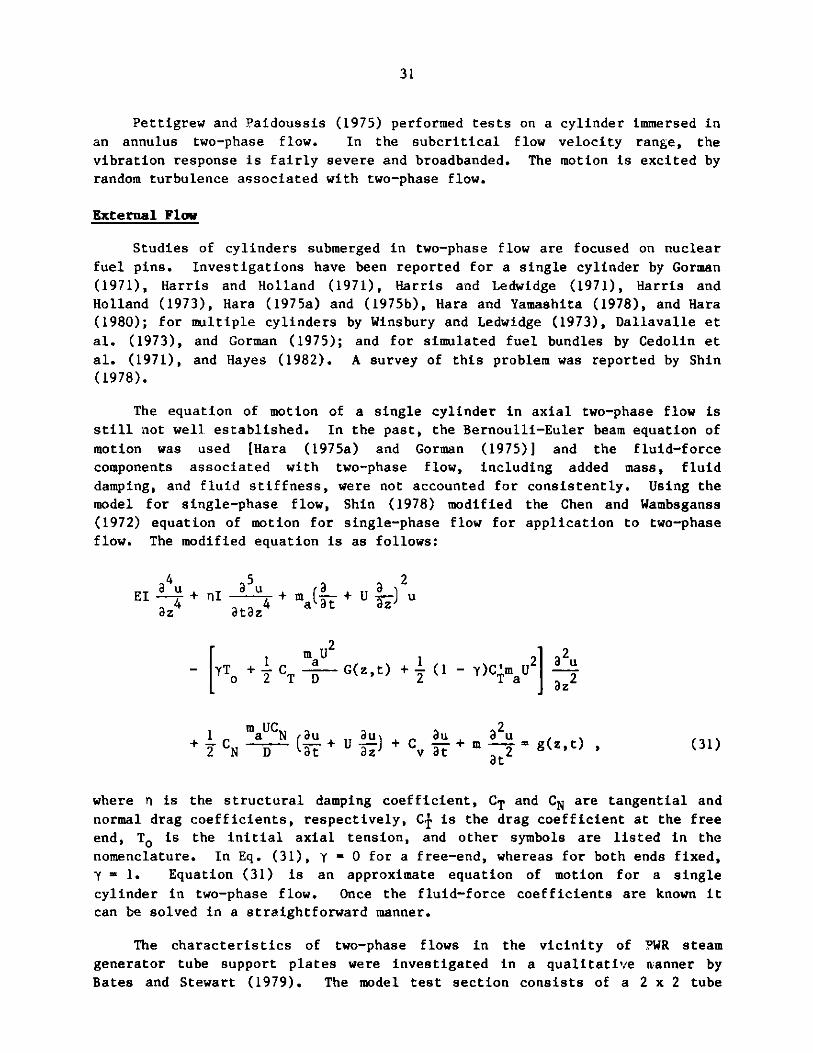
flow. The modified equation is as follows:
4 5 2
_ _ _ aaEI L+ nI u+m( + U)
2
- YTo+ CT D U G(z,t) + (1 - Y)C maU2Ia
1 maUCN au au au 2u+2CN D (a+UaJ+Cvt- + m -- = g(z,t) , (31)
at
where n is the structural damping coefficient, CT and CN are tangential and
normal drag coefficients, respectively, CT is the drag coefficient at the free
end, To is the initial axial tension, and other symbols are listed in the
nomenclature. In Eq. (31), y = 0 for a free-end, whereas for both ends fixed,
y = 1. Equation (31) is an approximate equation of motion for a single
cylinder in two-phase flow. Once the fluid-force coefficients are known it
can be solved in a straightforward manner.
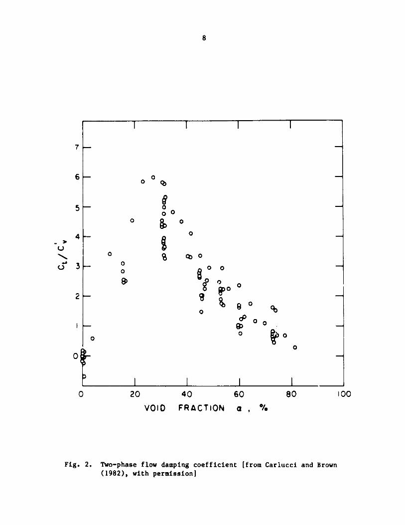
The characteristics of two-phase flows in the vicinity of PWR steam
generator tube support plates were investigated in a qualitative rLanner by
Bates and Stewart (1979). The model test section consists of a 2 x 2 tube
32
bundle fitted with prototypic support plates enclosed in a clear lucite flow
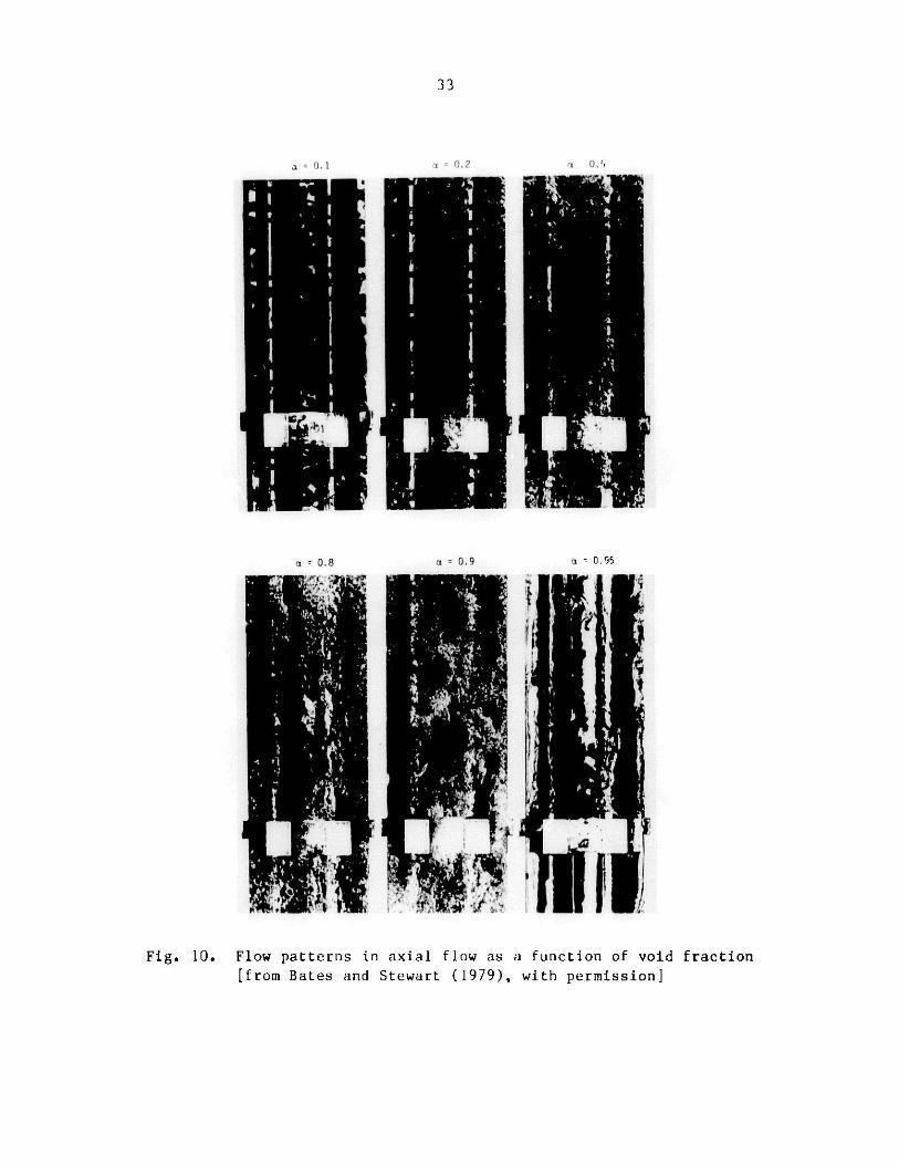
housing. Figure 10 shows the flow patterns for various values of void
fraction. Observations of both the in-operation test assembly and the high-
speed motion picture evidence reveal that very definite two-phase flow regimes
could be distinguished for different values of void fraction:
a = 0.1 - 0.3 -- Low turbulence, bubbly flow, with uniform-size bubbles
a = 0.4 - 0.7 -- More turbulent churning flow
a = 0.8 - 0.9 -- More separated, oscillatory chugging or plug flow
a = 0.95 -- Annular flow with the liquid phase concentrated on Lhe
wetted surfaces.
The driving force in two-phase flow originates from turbulence and bubble
impacts. In addition, the time-varying virtual mass along the cylinder gives
rise to the potential for parametric excitation. The phenomenon is the same
as that for internal flow. Experiments and analysis of parametric excitation
were performed by Hara (1980). Parametric resonance occurs when the ratio of
the natural frequency of the cylinder to the void slug frequency is equal to
0.5, 1, and 1.5, and resonance occurs when the ratio is equal to 1, 2, 3. The
analysis can be based on Eq. (31). Hara simplified the analysis by neglecting
the effect of drag forces. His experimental and analytical results agree
reasonably well [Hara (1980)].
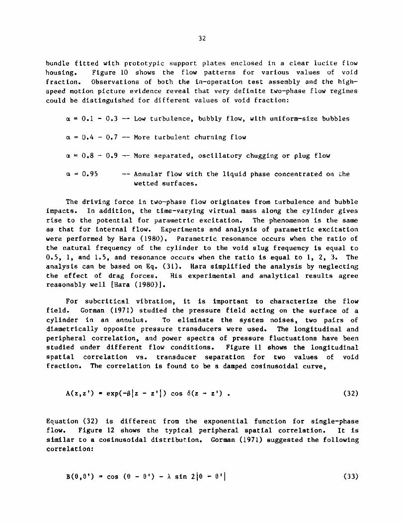
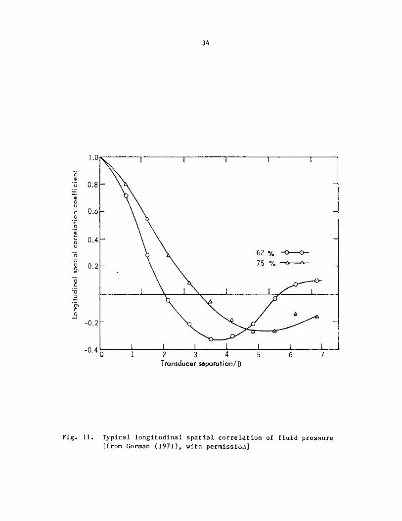
For subcritical vibration, it is important to characterize the flow
field. Gorman (1971) studied the pressure field acting on the surface of a
cylinder in an annulus. To eliminate the system noises, two pairs of
diametrically opposite pressure transducers were used. The longitudinal and
peripheral correlation, and power spectra of pressure fluctuations have been
studied under different flow conditions. Figure 11 shows the longitudinal
spatial correlation vs. transducer separation for two values of void
fraction. The correlation is found to be a damped cosinusoidal curve,
A(z,z') = exp(-01z - z'I) cos 6(z - z') . (32)
Equation (32) is different from the exponential function for single-phase
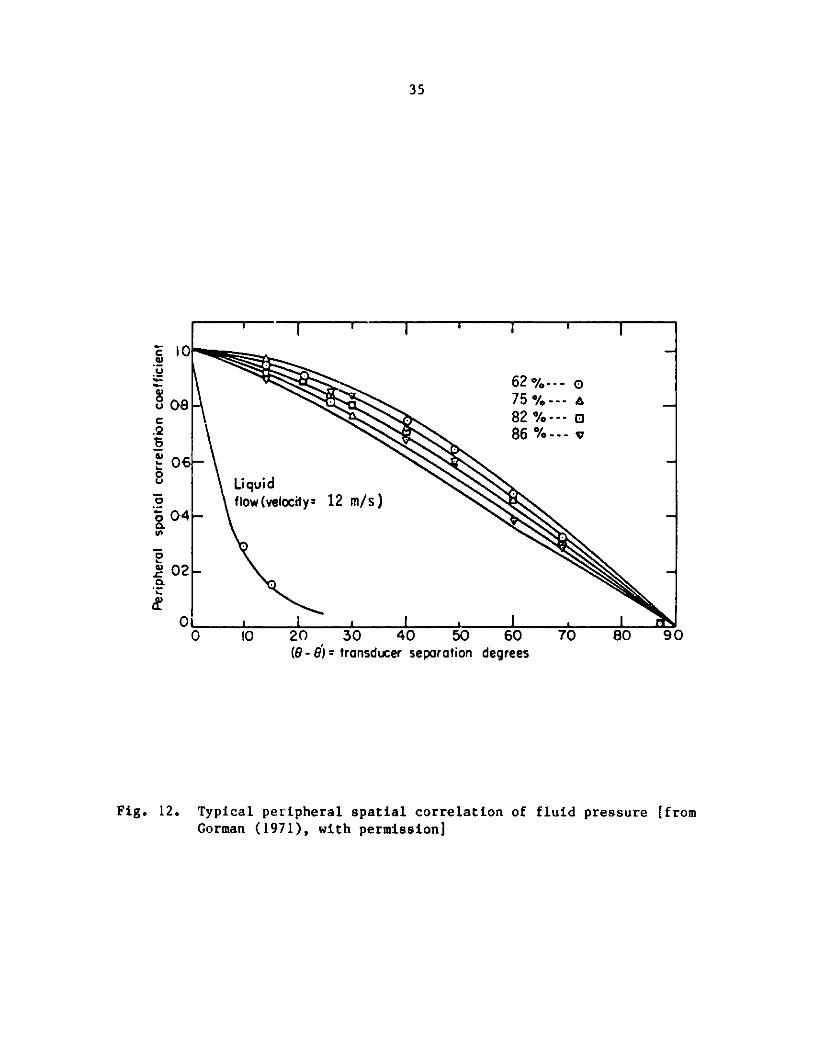
flow. Figure 12 shows the typical peripheral spatial correlation. It is
similar to a cosinusoidal distribution. Gorman (1971) suggested the following
correlation:
B(O,O') = cos (0 - 0') - A sin 216 - '| ((33)
33
0.8 ,i 0.9 0 95
Fig. 10. Flow patterns in axial flow as a function of void fraction
[from Bates and Stewart (1979), with permission]
34
T T
I I
6275
0 -
0
I I
1 2 3 4Transducer separation/D
5 6 7
Fig. 11. Typical longitudinal spatial correlation of fluid pressure[from Gorman (1971), with permission]
1.0
0.8-
0.6-
0.4-
0.2
C
U
0UC0
0
Q)
0
0)
c
2-3
-0.2K-
-0.4'C
lk v A AV AV Iff - -
I 1 L L
T T T
1 I
)
35
I0V
08
-2
06
04
S02
Oa0 10 20
(9-6)=30 40 50transducer separation degrees
60 70 80 90
Fig. 12. Typical peripheral spatial correlation of fluid pressure [fromGorman (1971), with permission]
' I I ' I
0-62%--- o
75%---" o
82 %--- o. 86 %--- v
Li qu id
f iow(veIoity= 12 m/s)
I I I I .a a a _ i
-- -- --
1,"
k
36
where A may be selected to best fit the curve associated with each void
fraction.
Based on Gorman's study (1971), several conclusions can be made:
" The mathematical model for single-phase flow is applicable for two-
phase flow provided proper fluid parameters are used.
" There is good agreement between the shape of the measured
displacement, the shape of the displacement predicted by the random
vibration theory, and the measured boundary-layer pressure fluctua-
tions. The vibration amplitude in two-phase flow is higher than that
in single-phase flow because of higher peripheral spatial correlation
of pressure fluctuations.
* Damping coefficients associated with the first mode were found to be
about four times as high as for liquid flow.
The effect of void fraction on cylinder response is of particular
interest. Detailed studies have been performed by Harris and Holland (1973)
and Winsbury and Ledwidge (1973). The cylinder response is found to be
proportional to an(1 - a), mass flux, and other parameters. The values of n
are given by Winsbury and Ledwidge (1973):
0.16 < a < 30 , n - 1.3
0.30 < a < 0.70 , n - 2.6 (34)
0.70 S a 0.94 , n - 5.2
Equation (34) is based on their own data and the results of others. For a
given mass flux, the maximum response occurs for 0.80 < a < 0.88.
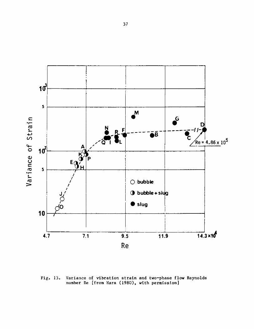
Hara (1980) studied the relation between vibration response and the
Reynold's number, which is defined as (1 + Qa/Q )DUZ/vR, where QA and Q, are
the flow rate of air and water, respectively. A typical result is shown in
Fig. 13. When Re is smaller than 6 x 10⁴, vibration is small; when
Re > 8.5 x 10 4, vibration is large.
The cylinder response for a simulated fuel rod in both a two-phase and
boiling flow were measured by Hayes (1982). The results show that the boiling
tests and two-phase inlet tests resulted in higher vibration than that
obtained in single-phase flow. For a constant mass flux, the fuel rod
vibration peaks at a particular void fraction in both, boiling and adiabatic,
two-phase flows.
37
4 ____ ______
I '+ --
M
- 5B
P
G
Re=
/ 1
C) bubble
Jbubble+sl
do 1 *slug
9.5
Re11.9
4.86x10
A14.3 x14
Fig. 13. Variance of vibration strain and two-phase flow Reynoldsnumber Re [from Hara (1980), with permission]
5
c)
(0O
N F
-01A
K'
E
102
5
10
4.7 7.1
38
V. CLOSING REMARKS
The effect of two-phase flow is much more complicated than that of
single-phase flow. This is attributed to the fluctuations of flow rate,
density and pressure gradients, as well as oscillations due to compressibility
of the fluid. The passage of bubbles is accompanied by microhydraulic
impacts, which produce fluctuation forces in two-phase flow. Therefore, in
addition to the pressure fluctuations encountered in single-phase flow, the
microhydraulic impacts associated with two-phase flow are very important.
The mechanisms of two-phase flow-induced vibration include subcritical
vibration excited by turbulence and bubble impacts, parametric resonance
associated with the periodic variation of mass flux, vortex-induced vibration
for small void fractions, and large amplitude oscillation of fluidelastic
instability. Reported studies of these phenomena for axial- and crossflow
indicate that progress has been made. However, investigations that are much
more systematic are needed. Several topical areas are important:
" Flow Field: Flow velocity distribution in heat transfer equipment,
distribution of bubbles, mathematical characterization of flow
patterns and effect of system parameters on flow field.
* Fluid Excitation Forces: Power spectral density of fluid excitation
forces, axial and peripheral correlation of fluid pressure
fluctuations, and effect of void fraction on fluid excitation forces.
" Motion-Dependent Fluid Forces: Added mass, fluid damping, and fluid
stiffness as a function of void fraction and flow rate for different
cylinder arrays as well as different oscillation frequencies.
* Cylinder Response: Mathematical models that incorporate all fluid
effects, simplified equations for different excitation mechanisms, and
response as a function of system parameters.
* Design Guides: Relationship between two-component (e.g., air-water)
two-phase flow and single-component (e.g., steam-water) two-phase
flow, design guides for predicting cylinder response, acceptance
criteria, and design modification techniques.
All of the above topics are very important and must be studied to resolve
the issues of two-phase flow-induced vibration and to provide the basis for
the development of prediction methods and design guides. Argonne National
Laboratory is planning a comprehensive research program to look into this
subject. A two-phase air-water loop is being designed. Experiments areexpected to begin in FY 1988. A series of tests will be performed to study
fluid excitation force, cylinder response, and motion-dependent fluid forces.
39
ACKNOWLEDQIKNTS
This work was sponsored by the U. S. Department of Energy (DOE), Office
of Energy Utilization Research, under the Energy Conversion and Utilization
Technologies (ECUT) Program. The continuing encouragement and support of
M. E. Gunn, J. J. Eberhardt, and W. H. Thielbahr of US/DOE are appreciated.
40
REFERENCES
Axisa, F., et al. 1984. Vibration of Tube Bundles Subjected to Air-Water andSteam-Water Cross Flow: Preliminary Results on Fluidelastic Instability. ASMESymposium on Flow-Induced Vibration, Vol. 2, pp. 269-284.
Axisa, F., et al. 1985. Vibration of Tube Bundles Subjected to Steam-WaterCross Flow: A Comparative Study of Square and Triangular Pitch Arrays. Trans.8th Int. Conf. on Structural Mechanics in Reactor Technology. Paper No. B1/2.
Axisa, F., et al. 1986. Flow-Induced Vibration of Steam Generator Tubes.EPRI NP-4559, Electric Power Research Institute, Palo Alto, CA.
Bates, J. M., and Stewart, C. W. 1979. Experimental Study of Single- andTwo-Phase Flow Fields Around PWR Steam Generator Tube Support Plates. EPRINP-1142, Research Project 1121, Electric Power Research Institute, Palo Alto,
CA.
Carlucci, L. N. 1980. Damping and Hydrodynamic Mass of a Cylinder inSimulated Two-Phase Flow. J. Mech. Des. 102, 597-602.
Carlucci, L. N., and Brown, J. D. 1983. Experimental Studies of Damping andHydrodynamic Mass of a Cylinder in Confined Two-Phase Flow. ASME Trans.; J.Vib., Acoust., Stress and Reliability in Des. 105, 83-89.
Cedolin, L., Hassid, A., Rossini, T., and Sobieri, R. 1971. VibrationsInduced by the Two-Phase Coolant Flow in the Power Channels of a Pressure TubeType Reactor. Trans. 1st Int. Conf. on Structural Mechanics in ReactorTechnology. Paper No. E4/5.
Chen, S. S. 1987. Flow-Induced Vibration of Circular CylindricalStructures. Hemisphere Publishing Co., New York.
Chen, S. S., and Chung, H. 1976. Design Guide for Calculating HydrodynamicMass, Part I: Circular Cylindrical Structures. ANL-CT-76-45, Argonne National
Laboratory, Argonne, IL.
Chen, S. S., and Jendrzejczyk, J. A. 1983. Stability of Tube Arrays inCrossflow. Nucl. Eng. Des. 75(3), 351-374.
Chen, S. S., and Jendrzejczyk, J. A. 1986. Fluid Excitation Forces Acting ona Tube Array. In Measuring and Metering of Unsteady Flows, ASME Publication,FED-Vol. 40, pp. 45-55.
Chen, S. S., and Jendrzejczyk, J. A. 1987. Characteristics of FluidelasticInstability of Tube Rows in Crossflow. Presented at the Int. Conf. on FlowInduced Vibration, Bowness-on-Windermere, England, May 12-14. Paper No. B3.
Chen, S. S., and Wambsganss, M. W. 1972. Parallel-Flow-Induced Vibration ofFuel Rods. Nucl. Eng. Des. 18, 253-278.
Chen, S. S., Wambsganss, M. W., and Jendrzejczyk, J. A. 1976. Added Mass andDamping of a Vibrating Rod in Confined Viscous Fluids. ASME Trans.; J. Apple.Mech. 43, 325-329.
41
Collier, J. G. 1981. Convective Boiling and Condensation, 2nd Ed. McGraw-Hill Book Company (U.K.) Ltd., New York.
Dallavalle, F., Rossini, T., and Vanoli, G. 1973. Vibrations Induced by aTwo-Phase Parallel Flow to a Rod Bundle: Preliminary Experiments on theSurface Tension and Gas Density Effect. Proc. Int. Symp. Vibration Problemsin Industry 5, No. 525, Keswick, England.
Gorman, D. J. 1971. An Analytical and Experimental Investigation of theVibration of Cylindrical Reactor Fuel Elements in Two-Phase Parallel Flow.Nucl. Sci. and Eng. 44, 277-290.
Gorman, D. J. 1975. Experimental and Analytical Study of Liquid and Two-Phase Flow Induced Vibration in Reactor Fuel Bundles. ASME Publications,Paper No. 75-PVP-2.
Goyder, H. G. D. 1987. Two-Phase Buffeting of Heat Exchanger Tubes.Presented at the Int. Conf. on Flow Induced Vibration, Bowness-on-Windermere,England, May 12-14. Paper No. E2
Grace, J. R., and Hosny, N. 1985. Forces on Horizontal Tubes in GasFluidized Beds. Chem. Eng. Res. Des. 63, 191-198.
Hara, F. 1973. A Theory on the Two-Phase Flow Induced Vibrations in PipingSystems. Trans. 2nd Int. Conf. on Structural Mechanics in Reactor Technology.Paper No. F5/15.
Hara, F. 1975a. A Theory on the Vibrations of a Fuel Pin Model in ParallelTwo-Phase Flow. Trans. 3rd Int. Conf. on Structural Mechanics in ReactorTechnology. Paper No. D2/4.
Hara, F. 1975b. Experimental Study of the Vibrations of a Fuel Pin Model inParallel Two-Phase Flow. Trans. 3rd Int. Conf. on Structural Mechanics inReactor Technology. Paper No. D2/3.
Hara, F. 1977. Two-Phase-Flow-Induced Vibrations in a Horizontal PipingSystem. Bull. JSME 20, 419-427.
Hara, F. 1980. Two-Phase Flow Induced Parametric Vibrations in Structural
Systems - Pipes and Nuclear Fuel Pins. Rep. Inst. Ind. Sci., Univ. Tokyo 28,Series 183, 1-43.
Hara, F. 1982. Two-Phase Cross-Flow-Induced Forces Acting on a CircularCylinder. ASME Publication, PVP-Vol. 63, pp. 9-17.
Hara, F. 1984. Air-Bubble Effects on Vortex-Induced Vibrations of a Circular
Cylinder. ASME Symposium on Flow-Induced Vibrations, Vol. 1, pp. 103-113.
Hara, F. 1987a. Vibration of a Single Row of circular Cylinders Subjected toTwo-Phase Bubble Cross-Flow. Presented at the Int. Conf. on Flow InducedVibration, Bowness-on-Windermere, England, May 12-14. Paper No. El.
Hara, F., 1987b. Vibrations of Circular Cylindrical Structures Subjected toTwo-Phase Cross Flows. JSME Int. J. 30(263), 711-722.
42
Hara, F., and Kohgo, 0. 1982. Added Mass and Damping of a Vibrating Rod in aTwo-Phase Air-Water Mixed Fluid. ASME Publication, PVP-Vol. 63, pp. 1-8.
Hara, F., and Kohgo, 0. 1986. Numerical Approach to Added Mass and Dampingof a Vibrating Circular Cylinder in a Two-Phase Bubble Fluid. In Proc. Int.Conf. on Computational Mechanics, 2, pp. Vi[-255.
Hara, F., Shigeta, T., and Shibata, H. 1974. Two-Phase Flow by InducedRandom Vibrations. In Flow-Induced Structural Vibrations, E. Naudascher, Ed.,pp. 691-700, Springer-Verlag, Berlin.
Hara, F., and Yamashita, T. 1978. Parallel Two-Phase-Flow-Induced Vibrationsin Fuel Pin Model. J. Nucl. Sci. Technol. 15, 346-354.
Harris, R. W., and Holland, P. G. 1971. Response of a Cylindrical Cantileverto Axial Air Water Flow. Trans. 1st Int. Conf. on Structural Mechanics inReactor Technology. Paper No. E3/6.
Harris, R. W., and Holland, P. G. 1973. An Experimental Study on Flow-Induced Vibration of a Cantilever in Axial Air-Water Flow. Trans. 2nd Int.Conf. on Structural Mechanics in Reactor Technology. Paper No. D3/4.
Harris, R. W., and Ledwidge, T. J. 1971. The Relationship Between theCoherence Length of a Two Phase Mixture and the Response of a CylindricalCantilever. Fourth Australasian Conf. on Hydraulics and Fluid mechanics,Monash Univ., Melbourne, Australia, Nov. 29-Dec. 3.
Hayes, C. G. 1982. Fuel Rod Vibration in Two-Phase Flow. GEAP-22077,General Electric, San Jose, CA.
Heilker, W. J., and Vincent, R. Q. 1980. Vibration in Nuclear HeatExchangers Due to Liquid and Two-Phase Flow. Presented at the Century 2Nuclear Engineering Conference, San Francisco, CA, Aug. 19-21. ASME Paper No.80-C2/NE-4.
Hosny, N., and Grace, J. R. 1983. Forces on a Tube Immersed within aFluidized Bed. In Fluidization, D. Kunii and R. Toei, Eds., pp. 111-120,Engineering Foundation, New York.
Hosny, N., and Grace, J. R. i984. Transient Forces on Tubes within an Arrayin a Fluidized Bed. AIChE J. 30, 974-976.
Kennedy, T. C., Konovan, J. E., and Taigas, A. 1981. Forces on ImmersedTubes in Fluidized Beds. AIChE J. 27, 351-357.
Nakamura, T., et al. 1982. An Experimental Study on Exciting Forces by Two-Phase Cross-Flow. ASME Publication, PVP-Vol. 63, pp. 19-29.
Nakamura, T., and Fujita, K. 1987. A Study on Impact Vibration of LooselyHeld Tube by Cross Flow. Presented at the Int. Conf. on Flow InducedVibration, Bowness-on-Windermere, England, May 12-14. Paper No. KI.
43
Pettigrew, M. J., and Gorman, D. J. 1973. Experimental Studies on Flow-Induced Vibration to Support Steam Generator Design; Part III: Vibration ofSmall Tube Bundles in Liquid and Two-Phase Cross-Flow. Presented at the Int.Symp. on Vibration Problems in Industry, Keswick, England, April 10-14.
Pettigrew, M. J., and Gorman, D. J. 1978. Vibration of Heat ExchangeComponents in Liquid and Two-Phase Cross-Flow. Int. Conf. on Vibration inNuclear Plant, Keswick, England, May 9-12.
Pettigrew, M. J., and Paidoussis, M. P. 1975. Dynamics and Stability ofFlexible Cylinders Subjected to Liquid and Two-Phase Axial Flow in ConfinedAnnuli. Presented at the 3rd Int. Conf. on Structural Mechanics in Reactor
Technology, London, U.K., Sept. 1-5.
Pettigrew, M. J., Tromp, J. H., and Mastorakos, J. 1985. Vibration of TubeBundles Subjected to Two-Phase Cross-Flow. J. Pressure Vessel Technol. 107,335-343.
Remy, F. N. 1982. Flow Induced Vibration of Tube Bundles in Two Phase CrossFlow. Third Keswick International Conference, English Lakes, U.K., May 11-14.
Schumann, V. 1981. Virtual Density and Speed of Sound in a Fluid-SolidMixture with Periodic Structures. Int. J. Multiphase Flow 7, 619-633.
Shin, Y. W. 1978. Two-Phase Flow-Induced Vibrations of Rods in ParallelFlow: A State-of-the-Art Review. GEAP-24148; ANL-CT-78-18, Argonne NationalLaboratory, Argonne, IL.
Skop, R. A., Ramberg, S. E., and Fever, K. M. 1976. Added Mass and DampingForces on Circular Cylinders. ASME Publication, Paper No. 76-PET-3.
Tanaka, H., and Takahara, S. 1981. Fluid Elastic Vibration of Tube Array inCross-Flow. J. Sound Vib. 77, 19-37.
Taylor, C. E., Pettigrew, M. J., Axisa, F., and Villard, B. 1986.Experimental Determination of Single and Two-Phase Cross Flow-Induced Forceson Tube Rows. In Flow-Induced Vibration - 1986, ASME Publication,PVP-Vol. 104, pp. 31-39.
Turner, M. J., and Irving, D. 1982. Forces on Tubes Immersed in a FluidizedBed. In Proc. of the 7th Int. Conf. on Fluidized Bed Combustion, Vol. 2,pp. 831-839.
Winsbury, G. J., and Ledwidge, T. J. 1973. An Experimental Study ofVibration of a Cluster of Flexible Hollow Cylinders in Axial Air-Water Flow.Trans. 2nd Int. Conf. on Structural Mechanics in Reactor Technology. PaperNo. D3/5.
Yih, T. S., and Griffith, P. 1970. Unsteady Momentum Fluxes in Two-PhaseFlow and the Vibration of Nuclear System Components. Proc. of the Conf. onFlow-Induced Vibrations in Reactor System Components, Argonne NationalLaboratory, Argonne, IL, May 14-15.
Yoshikawa, N., and Hara, F. 1985. Vibrations of a Single Row of CircularCylinders Subjected to Two-Phase Cross-Flow. (in Japanese). Trans. JSME 51,pp. 2487.
44
Distribution for ANL-87-28
Internal:
H. Drucker T. M. MulcahyR. W. Weeks W. T. Sha
C. A. Kot Y. W. ShinM. W. Wambsganss K. E. Kasza
R. E. Holtz A. ThomasW. W. Schertz E. M. StefanskiS. S. Chen (15) ANL Patent Dept.H. H. Chung ANL Contract FileH. Halle ANL LibrariesJ. A. Jendrzejczyk TIS Files (5)
External:
DOE-TIC for distribution per UC-95f (168)Manager, Chicago Operations Office, DOEDirector, Technology Management Div., DOE-CHD. L. Bray, DOE-CHA. L. Taboas, DOE-CHC. B. Alcock, University of Toronto, Toronto, Ontario, CanadaP. G. Shewmon, Ohio State University, Columbus, OHH. L. Anderson, Ontario HydroM. K. Au-Yang, B&WK. J. Bell, Oklahoma State Univ.A E. Bergles, Iowa State Univ.M. D. Bernstein, FWECR. D. Blevins, Rohr IndustriesJ. C. Blomgren, Commonwealth EdisonG. N. Bogel, Dow ChemicalG. J. Bohm, Westinghouse PWR SystemsG. Borushko, Westfield, NJJ. J. Brogan, DOE/ConservationG. M. Cameron, ChemeticsC. A. Chandley, TVAS. Chandra, Northeast UtilitiesP. Y. Chen, NRCJ. M. Chenoweth, HTRIM. A. Chionchio, Southwestern Eng.D. Chisholm, HTRIH. J. Connors, Westinghouse R&DR. J. Croke, Lummus Co.J. L. Dixon, Southern Heat Exch. Corp.J. J. Eberhardt, DOE/ConservationF. L. Eisinger, FWECR. L. Eshleman, Vibration InstituteD. F. Fijas, American StandardR. J. Fritz, GE/KAPLN. R. Gainsboro, Southwestern Eng.C. C. Gentry, Phillips Petroleum CompanyR. Ghattas, QuadrexJ. S. Gosnell, Braidwood Nucl. Power Station
45
S.K.M.R.M.K.
G.T.T.W.L.
T.D.N.R.B.D.A.
S.
A.R.
E.J.F.W.P.
M.S.B.
P.
A.P.A.T.
K.E.
S.R.A.S.T.
J.J.S.R.
D.E.
Green, EPRIG. Grinnell, Graham Mfg. Co.E. Gunn, DOE/ConservationT. Hartlen, Ontario Hydro
Hartzmann, NRC/NRRH. Haslinger, CEHausenbauer, Struther-WellsG. Haynes, Duke PowerD. Hazell, Foster Wheeler, EnglandJ. Heilker, CEW. Heilman, Nooter Corp.G. Heilmann, ChemeticsM. Himmelblau, U. Texas at AustinHirota, EPRI
Hutchensen, Battelle, PNLJohnson, Pacific Northwest
L. Johnson, M. W. Kellogg CompanyE. Jones, du Pont
P. Kalra, EPRI
V. Karvelis, Borg-WarnerA. Kenny, CEKiss, General Electric Co.H. Kissel, American StandardKreith, SERILampert, Vapor CorporationA. Larsen, Amoco Oil Co.LeFevre, Research CottrellF. Lindsey, Duke PowerT. Lubin, CEJ. Marto, U.S. Naval PostgraduateSchoolJ. Meehan, Word IndustriesM. Moretti, Oklahoma State Univ.Morris, TVAJ. Muldoon, Heat Transfer
SpecialistsNelson, Manning & Lewis Eng.H. Novendstern, WestinghouseElectric Corp.Oppegaard, Commonwealth EdisonPenney, A. E. Staley CompanyPoureshmenantalemy, Dravo Engrs.Proctor, Monsanto CompanyJ. Rabas, Westinghouse Electric
Corp.Rajan, NRCF. Reiss, Commonwealth Edison
Richlen, DOE/OIPB. Ritter, Fluor Engrs
& Constructors
Rockwell, Lehigh UniversityRodriguez, General Dynamics
T. M. Rudy, Exxon R&D LabsJ. B. Sandifer, B&W/ARCS. D. Savkar, GE/CRDM. Sax, Westinghouse BettisW. Schneider, B&W/CanadaJ. E. Schroeder, Nooter CorporationR. K. Shah, Harrison RadiatorW. Simmons, General DynamicsJ. C. Simonis, Southwest Res. Inst.L. L. Simpson, Union CarbideK. P. Singh, Holtec InternationalN. R. Singleton, Westinghouse
Electric Corp.D. Steininger, EPRIA. L. Sudduth, Duke Power Co.J. Taborek, Austin, TXK. K. Tam, Amoco Oil Co.W. H. Thielbahr, DOE/IDM. R. Torres, General ElectricS. N. Tower, Westinghouse MonroevilleJ. Tsou, EPRIM. E. Underwood, Badger Co.G. H. Weidenhamer, NRC/RESJ. Yampolsky, GA Technologies, Inc.E. Young, University of MichiganE. A. Zanoni, Westinghouse Bettis


![[X] EXPEDITE](https://img.pdfslide.us/doc/110x75/6290ebe975ad8d306424d00c/x-expedite.jpg)