Embed Size (px)
Citation preview
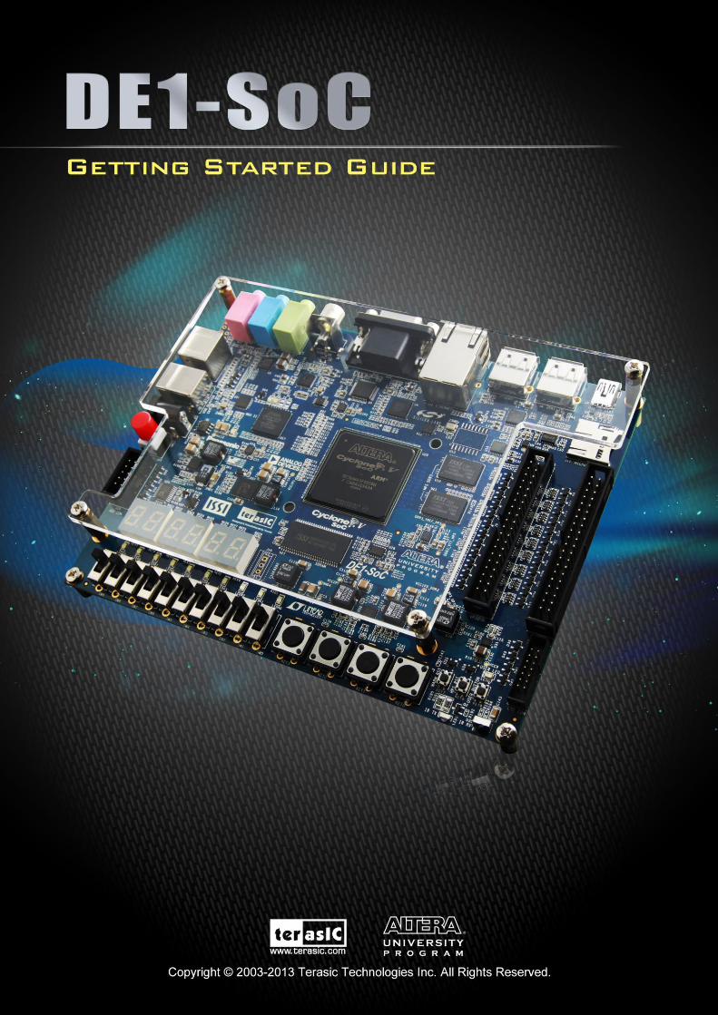
DE1-SoC Getting Started Guide
February 18, 2014
www.terasic.com.tw
1
DE1-SoC Getting Started Guide
February 18, 2014
www.terasic.com.tw
2
CONTENTS
CHAPTER 1 ABOUT THIS GUIDE .............................................................................................................................. 3
CHAPTER 2 SOFTWARE INSTALLATION ................................................................................................................ 4
2.1 INTRODUCTION ........................................................................................................................................................... 4
2.2 INSTALLING QUARTUS II SOFTWARE............................................................................................................................ 4
2.3 INSTALLING ALTERA SOC EMBEDDED DESIGN SUITE ................................................................................................. 7
CHAPTER 3 DEVELOPMENT BOARD SETUP ...................................................................................................... 11
3.1 INTRODUCTION ......................................................................................................................................................... 11
3.2 DEFAULT MSEL SETTINGS ........................................................................................................................................ 11
3.3 USB AND POWER CABLES......................................................................................................................................... 12
3.4 POWERING UP THE DE1-SOC BOARD ........................................................................................................................ 12
CHAPTER 4 PERFORMING A FPGA SYSTEM TEST........................................................................................... 13
4.1 INTRODUCTION ......................................................................................................................................................... 13
4.2 INSTALLING THE USB-BLASTER II DRIVER ............................................................................................................... 13
4.3 DOWNLOADING A FPGA SRAM OBJECT FILE .......................................................................................................... 14
CHAPTER 5 RUNNING LINUX ON THE DE1-SOC BOARD ................................................................................ 21
5.1 INTRODUCTION ......................................................................................................................................................... 21
5.2 CREATING A MICROSD CARD IMAGE ......................................................................................................................... 21
5.3 SETTING UP UART TERMINAL .................................................................................................................................. 22
5.4 RUNNING LINUX ON DE1-SOC BOARD ..................................................................................................................... 25
CHAPTER 6 RUNNING LXDE ON THE DE1-SOC BOARD .................................................................................. 26
6.1 INTRODUCTION ......................................................................................................................................................... 26
6.2 MAKING LXDE BOOT SD CARD............................................................................................................................... 27
6.3 LXDE SETTING UP PROCEDURES ............................................................................................................................. 27
ADDITIONAL INFORMATION ....................................................................................................................................... 29
DE1-SoC Getting Started Guide
February 18, 2014
www.terasic.com.tw
3
Chapter 1
About this Guide
The DE1-SoC Getting Started Guide contains a quick overview of the hardware and software setup
including step-by-step procedures from installing the necessary software tools to using the DE1-SoC
board. The main topics that this guide covers are listed below:
Software Installation: Installing Quartus II and SoC EDS
Development Board Setup: Powering on the DE1-SoC
Perform FPGA System Test: Downloading a FPGA SRAM Object File (.sof)
Running Linux on DE1-SoC Board
DE1-SoC Getting Started Guide
February 18, 2014
www.terasic.com.tw
4
Chapter 2
Software Installation
22..11 IInnttrroodduuccttiioonn
This section explains how to install the following software:
Altera Quartus II software
Altera SoC Embedded Design Suite
Note: 64-bit OS required
22..22 IInnssttaalllliinngg QQuuaarrttuuss IIII ssooffttwwaarree
The Altera Complete Design Suite provides the necessary tools used for developing hardware and
software solutions for Altera FPGAs. The Quartus II software is the primary FPGA development tool
used to create reference designs along with the Nios II soft-core embedded processor integrated
development environment
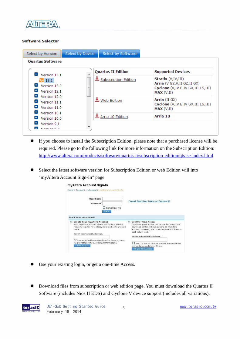
User can download the latest software from https://www.altera.com/download/dnl-index.jsp
DE1-SoC Getting Started Guide
February 18, 2014
www.terasic.com.tw
5
If you choose to install the Subscription Edition, please note that a purchased license will be
required. Please go to the following link for more information on the Subscription Edition:
http://www.altera.com/products/software/quartus-ii/subscription-edition/qts-se-index.html
Select the latest software version for Subscription Edition or web Edition will into
"myAltera Account Sign-In" page
Use your existing login, or get a one-time Access.
Download files from subscription or web edition page. You must download the Quartus II
Software (includes Nios II EDS) and Cyclone V device support (includes all variations).
DE1-SoC Getting Started Guide
February 18, 2014
www.terasic.com.tw
6
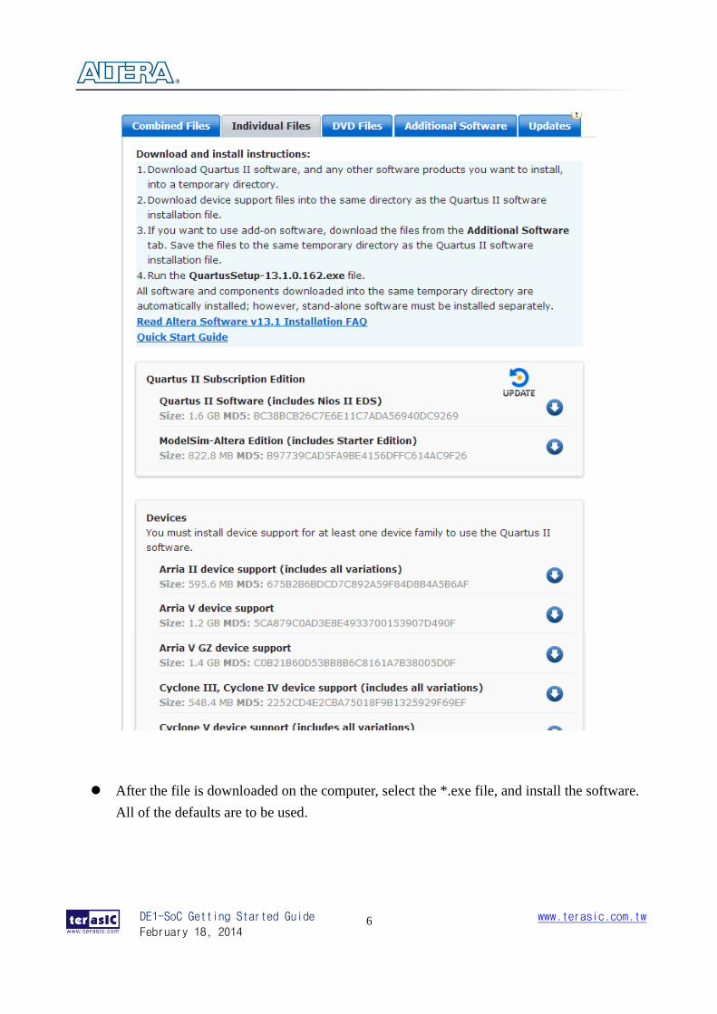
After the file is downloaded on the computer, select the *.exe file, and install the software.
All of the defaults are to be used.
DE1-SoC Getting Started Guide
February 18, 2014
www.terasic.com.tw
7
22..33 IInnssttaalllliinngg AAlltteerraa SSooCC EEmmbbeeddddeedd DDeessiiggnn SSuuiittee
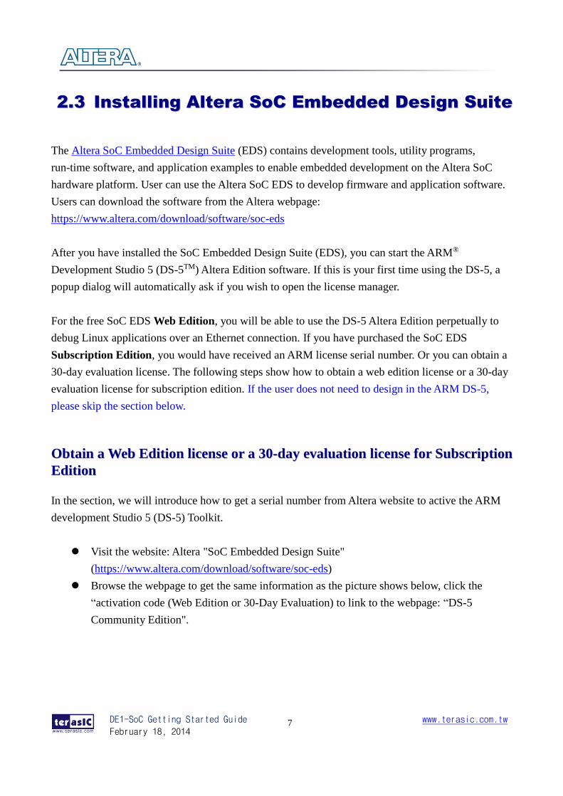
The Altera SoC Embedded Design Suite (EDS) contains development tools, utility programs,
run-time software, and application examples to enable embedded development on the Altera SoC
hardware platform. User can use the Altera SoC EDS to develop firmware and application software.
Users can download the software from the Altera webpage:
https://www.altera.com/download/software/soc-eds
After you have installed the SoC Embedded Design Suite (EDS), you can start the ARM®
Development Studio 5 (DS-5TM) Altera Edition software. If this is your first time using the DS-5, a
popup dialog will automatically ask if you wish to open the license manager.
For the free SoC EDS Web Edition, you will be able to use the DS-5 Altera Edition perpetually to
debug Linux applications over an Ethernet connection. If you have purchased the SoC EDS
Subscription Edition, you would have received an ARM license serial number. Or you can obtain a
30-day evaluation license. The following steps show how to obtain a web edition license or a 30-day
evaluation license for subscription edition. If the user does not need to design in the ARM DS-5,
please skip the section below.
OObbttaaiinn aa WWeebb EEddiittiioonn lliicceennssee oorr aa 3300--ddaayy eevvaalluuaattiioonn lliicceennssee ffoorr SSuubbssccrriippttiioonn
EEddiittiioonn
In the section, we will introduce how to get a serial number from Altera website to active the ARM
development Studio 5 (DS-5) Toolkit.
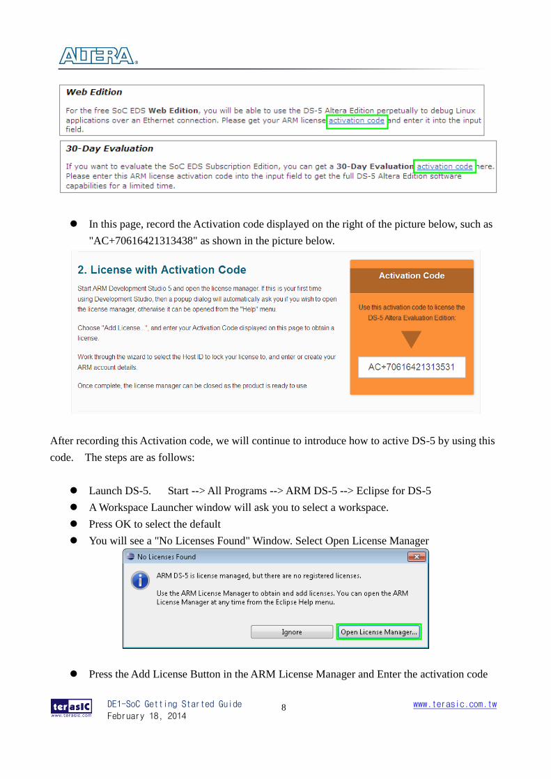
Visit the website: Altera "SoC Embedded Design Suite"
(https://www.altera.com/download/software/soc-eds)
Browse the webpage to get the same information as the picture shows below, click the
“activation code (Web Edition or 30-Day Evaluation) to link to the webpage: “DS-5
Community Edition".
DE1-SoC Getting Started Guide
February 18, 2014
www.terasic.com.tw
8
In this page, record the Activation code displayed on the right of the picture below, such as
"AC+70616421313438" as shown in the picture below.
After recording this Activation code, we will continue to introduce how to active DS-5 by using this
code. The steps are as follows:
Launch DS-5. Start --> All Programs --> ARM DS-5 --> Eclipse for DS-5
A Workspace Launcher window will ask you to select a workspace.
Press OK to select the default
You will see a "No Licenses Found" Window. Select Open License Manager
Press the Add License Button in the ARM License Manager and Enter the activation code
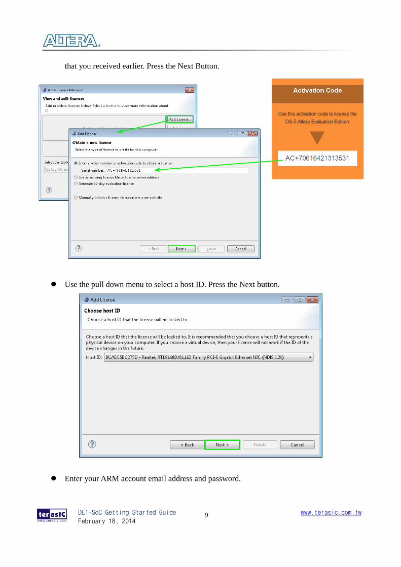
DE1-SoC Getting Started Guide
February 18, 2014
www.terasic.com.tw
9
that you received earlier. Press the Next Button.
Use the pull down menu to select a host ID. Press the Next button.
Enter your ARM account email address and password.
DE1-SoC Getting Started Guide
February 18, 2014
www.terasic.com.tw
10
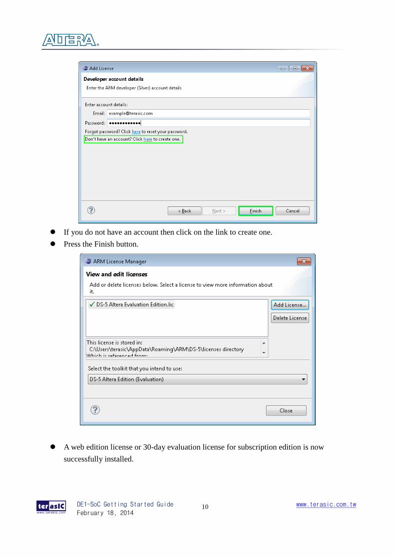
If you do not have an account then click on the link to create one.
Press the Finish button.
A web edition license or 30-day evaluation license for subscription edition is now
successfully installed.
DE1-SoC Getting Started Guide
February 18, 2014
www.terasic.com.tw
11
Chapter 3
Development Board Setup
33..11 IInnttrroodduuccttiioonn
The instructions in this section explain how to set up the DE1-SoC development board. The
following pictures show the board overview of DE1-SoC board.
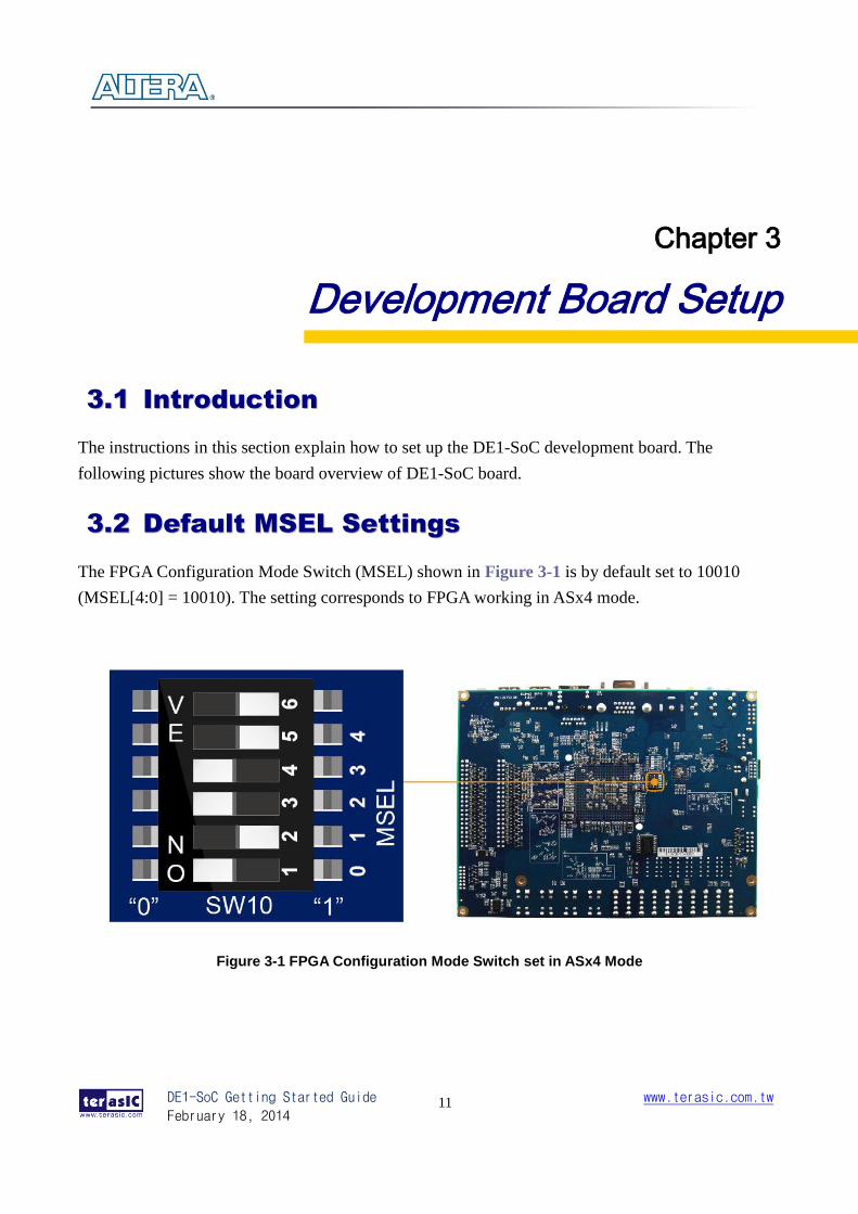
33..22 DDeeffaauulltt MMSSEELL SSeettttiinnggss
The FPGA Configuration Mode Switch (MSEL) shown in Figure 3-1 is by default set to 10010
(MSEL[4:0] = 10010). The setting corresponds to FPGA working in ASx4 mode.
Figure 3-1 FPGA Configuration Mode Switch set in ASx4 Mode
DE1-SoC Getting Started Guide
February 18, 2014
www.terasic.com.tw
12
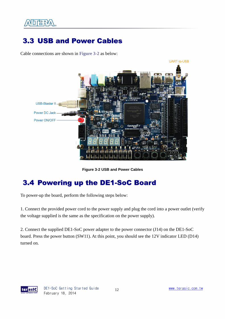
33..33 UUSSBB aanndd PPoowweerr CCaabblleess
Cable connections are shown in Figure 3-2 as below:
Figure 3-2 USB and Power Cables
33..44 PPoowweerriinngg uupp tthhee DDEE11--SSooCC BBooaarrdd
To power-up the board, perform the following steps below:
1. Connect the provided power cord to the power supply and plug the cord into a power outlet (verify
the voltage supplied is the same as the specification on the power supply).
2. Connect the supplied DE1-SoC power adapter to the power connector (J14) on the DE1-SoC
board. Press the power button (SW11). At this point, you should see the 12V indicator LED (D14)
turned on.
DE1-SoC Getting Started Guide
February 18, 2014
www.terasic.com.tw
13
Chapter 4
Performing a FPGA System Test
44..11 IInnttrroodduuccttiioonn
This chapter shows how to install the USB-Blaster II driver and download a FPGA SRAM Object
(.sof) file to your FPGA board.
44..22 IInnssttaalllliinngg tthhee UUSSBB--BBllaasstteerr IIII DDrriivveerr
The steps below outline how to install the USB-Blaster II driver.
1. Connect your computer to the development board by plugging the USB cable into the USB
connector (J13) of DE1-SoC (connection shown in Figure 3-2)
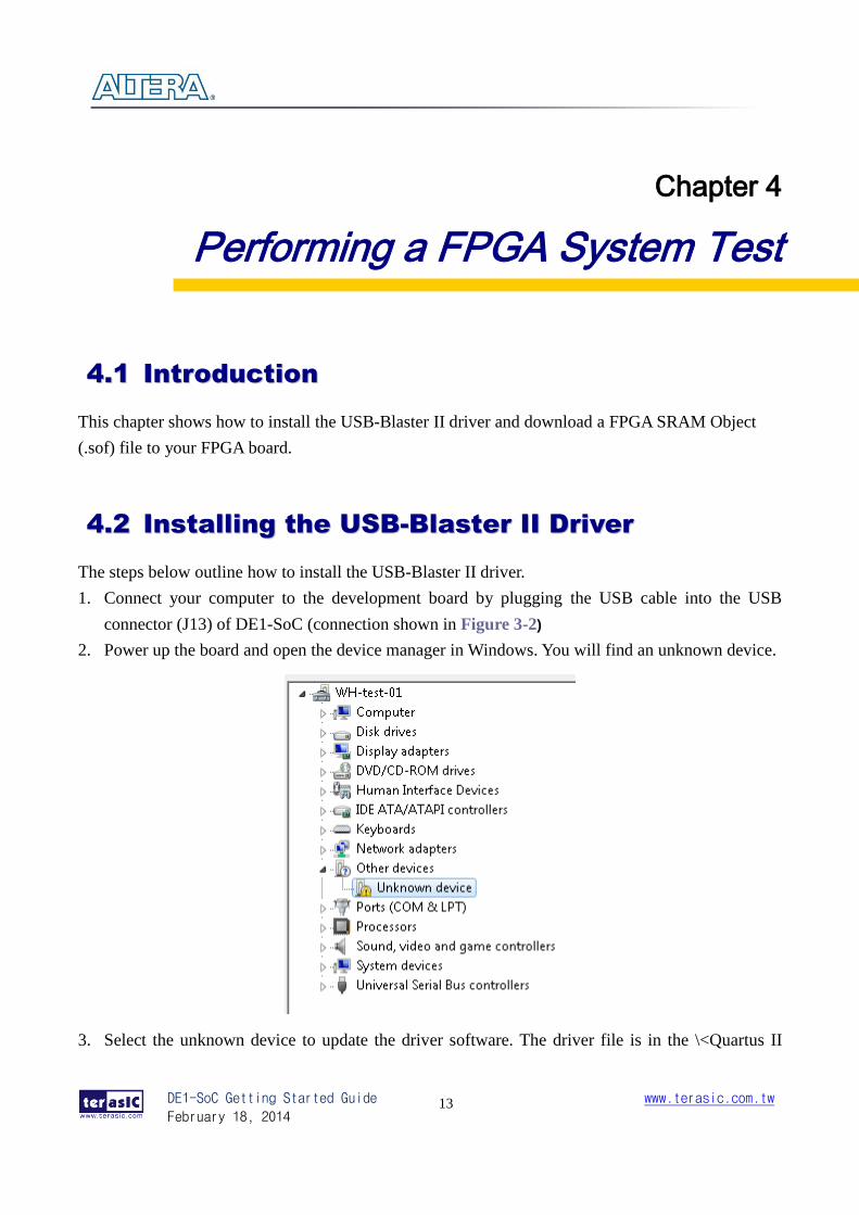
2. Power up the board and open the device manager in Windows. You will find an unknown device.
3. Select the unknown device to update the driver software. The driver file is in the \<Quartus II
DE1-SoC Getting Started Guide
February 18, 2014
www.terasic.com.tw
14
installation directory>\drivers\ usb-blaster-ii directory.
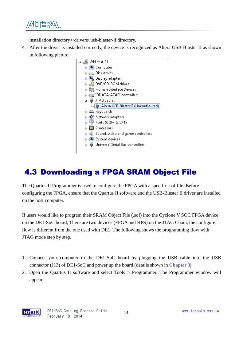
4. After the driver is installed correctly, the device is recognized as Altera USB-Blaster II as shown
in following picture.
44..33 DDoowwnnllooaaddiinngg aa FFPPGGAA SSRRAAMM OObbjjeecctt FFiillee
The Quartus II Programmer is used to configure the FPGA with a specific .sof file. Before
configuring the FPGA, ensure that the Quartus II software and the USB-Blaster II driver are installed
on the host computer.
If users would like to program their SRAM Object File (.sof) into the Cyclone V SOC FPGA device
on the DE1-SoC board, There are two devices (FPGA and HPS) on the JTAG Chain, the configure
flow is different from the one used with DE1. The following shows the programming flow with
JTAG mode step by step.
1. Connect your computer to the DE1-SoC board by plugging the USB cable into the USB
connector (J13) of DE1-SoC and power up the board (details shown in Chapter 3)
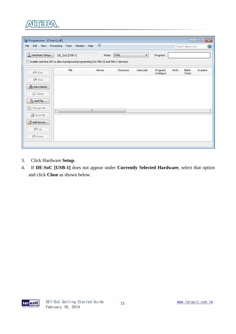
2. Open the Quartus II software and select Tools > Programmer. The Programmer window will
appear.
DE1-SoC Getting Started Guide
February 18, 2014
www.terasic.com.tw
15
3. Click Hardware Setup.
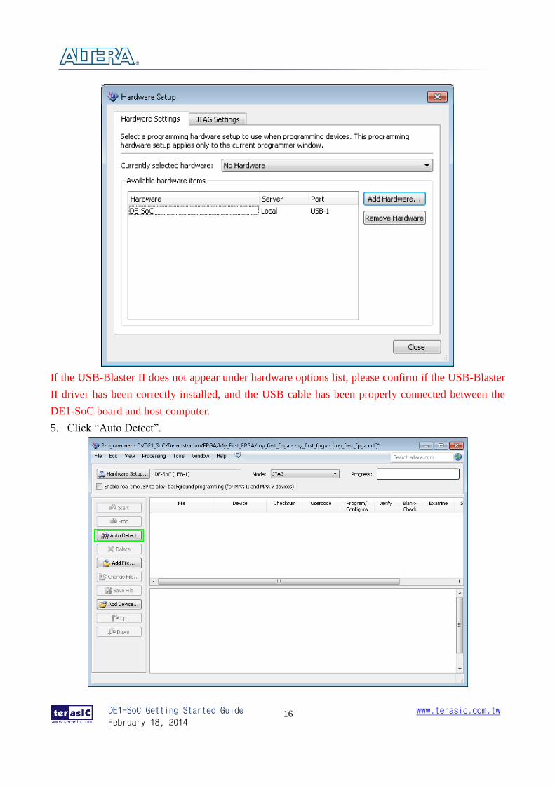
4. If DE-SoC [USB-1] does not appear under Currently Selected Hardware, select that option
and click Close as shown below.
DE1-SoC Getting Started Guide
February 18, 2014
www.terasic.com.tw
16
If the USB-Blaster II does not appear under hardware options list, please confirm if the USB-Blaster
II driver has been correctly installed, and the USB cable has been properly connected between the
DE1-SoC board and host computer.
5. Click “Auto Detect”.
DE1-SoC Getting Started Guide
February 18, 2014
www.terasic.com.tw
17
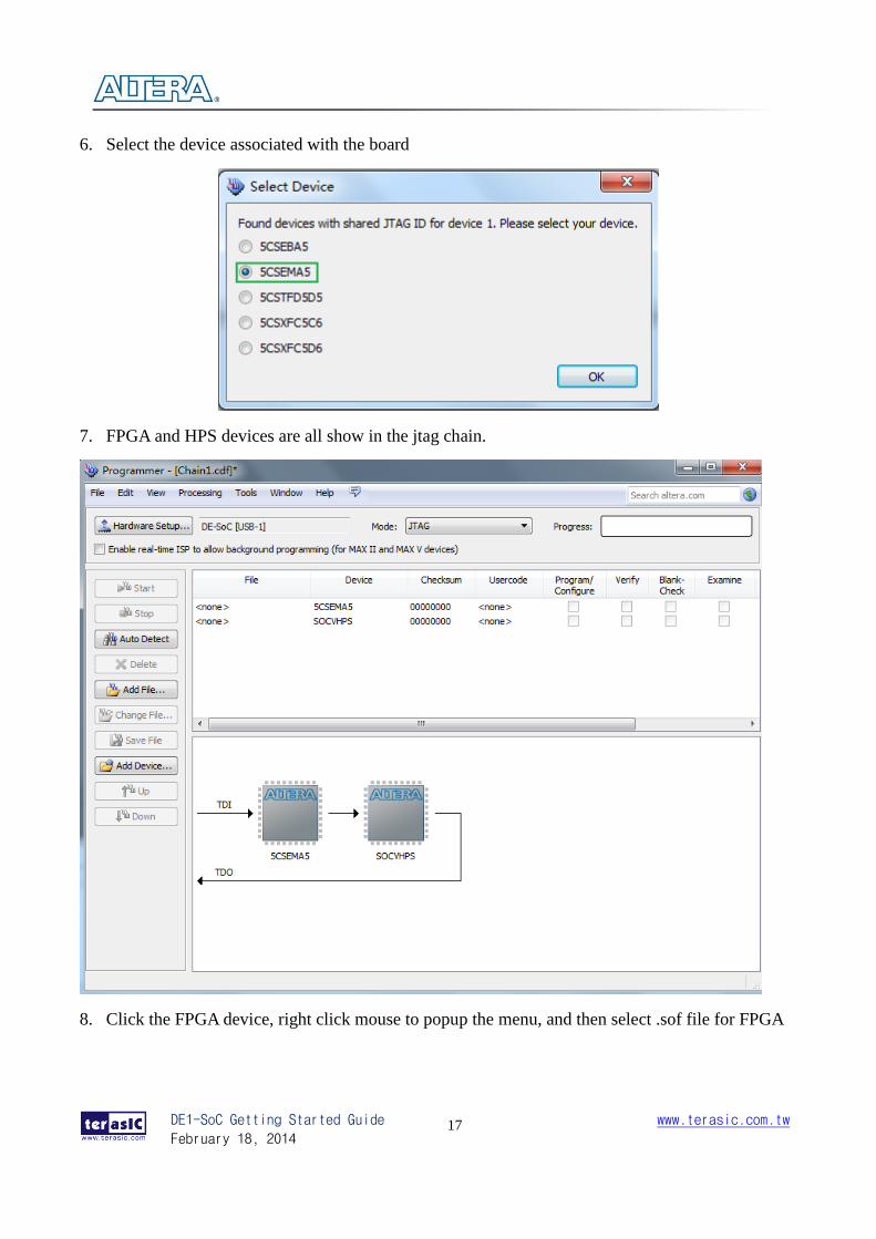
6. Select the device associated with the board
7. FPGA and HPS devices are all show in the jtag chain.
8. Click the FPGA device, right click mouse to popup the menu, and then select .sof file for FPGA
DE1-SoC Getting Started Guide
February 18, 2014
www.terasic.com.tw
18
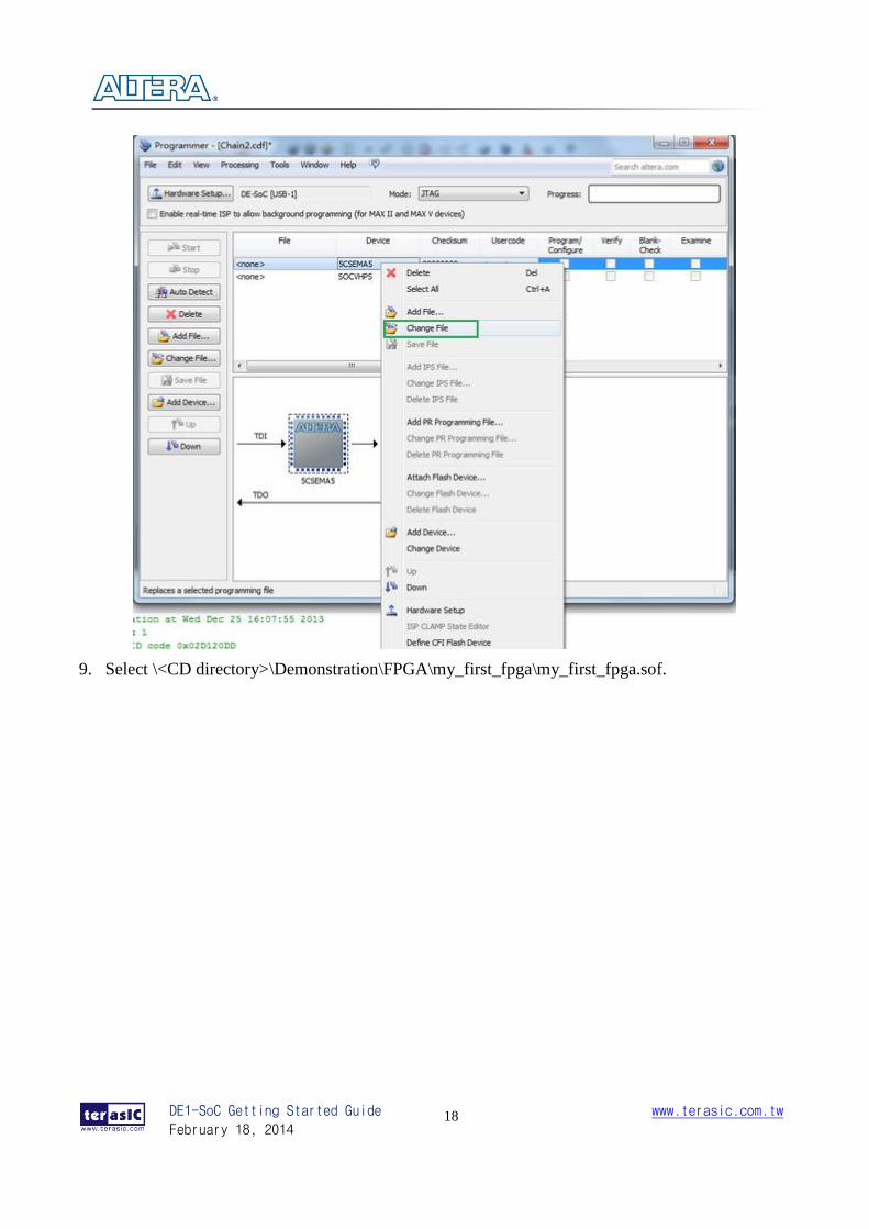
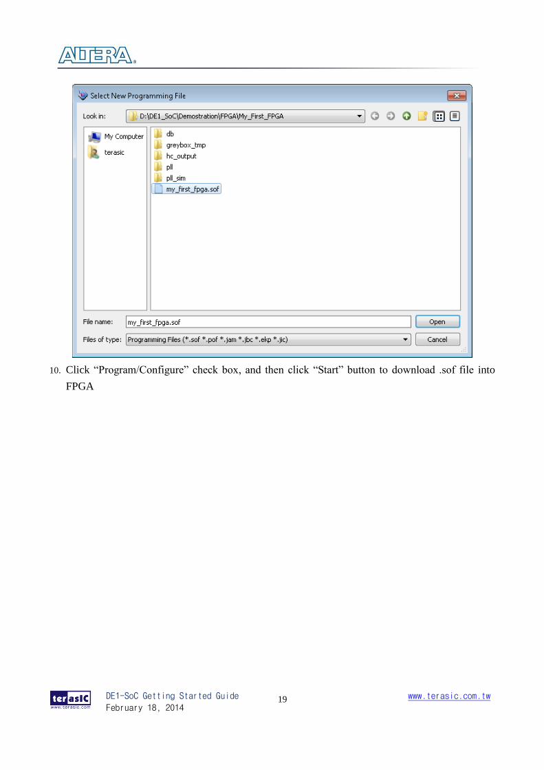
9. Select \<CD directory>\Demonstration\FPGA\my_first_fpga\my_first_fpga.sof.
DE1-SoC Getting Started Guide
February 18, 2014
www.terasic.com.tw
19
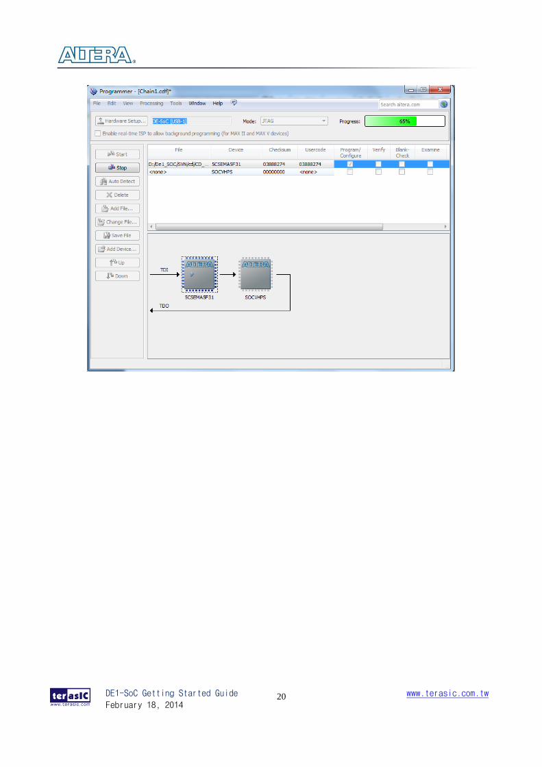
10. Click “Program/Configure” check box, and then click “Start” button to download .sof file into
FPGA
DE1-SoC Getting Started Guide
February 18, 2014
www.terasic.com.tw
20
DE1-SoC Getting Started Guide
February 18, 2014
www.terasic.com.tw
21
Chapter 5
Running Linux on the DE1-SoC board
55..11 IInnttrroodduuccttiioonn
This chapter demonstrates how to create a Micro SD card image, set up a UART Terminal, and run
Linux on DE1-SoC Board. User can download the latest SD Card image file from Terasic’s website
(Choose Linux Console in Linux BSP (Board Support Package)): http://cd_de1-soc.terasic.com.
55..22 CCrreeaattiinngg aa mmiiccrrooSSDD CCaarrdd IImmaaggee
To program a microSD card Linux image you can use a free tool called Win32DiskImager.exe from
http://sourceforge.net/projects/win32diskimager/ on a Windows machine.
MMiiccrrooSSDD SSppeecciiffiiccaattiioonn
Capacity: 4GB minimum
Speed: Class 4 (at least)
PPrree--bbuuiilltt SSDD CCaarrdd IImmaaggee
The pre-built binaries are delivered as an archive named DE1_SoC_SD.img. This SD card image
file contains all the items that are needed to run Linux on DE1-SoC board. (You can download the
compressed file from the link: http://www.terasic.com/downloads/cd-rom/de1-soc/linux_BSP/DE1_SoC_SD.zip.
And extract file to get the image file after downloading)
SPL Pre-loader
U-boot
Device Tree Blob
Linux Kernel
Linux Root File system
DE1-SoC Getting Started Guide
February 18, 2014
www.terasic.com.tw
22
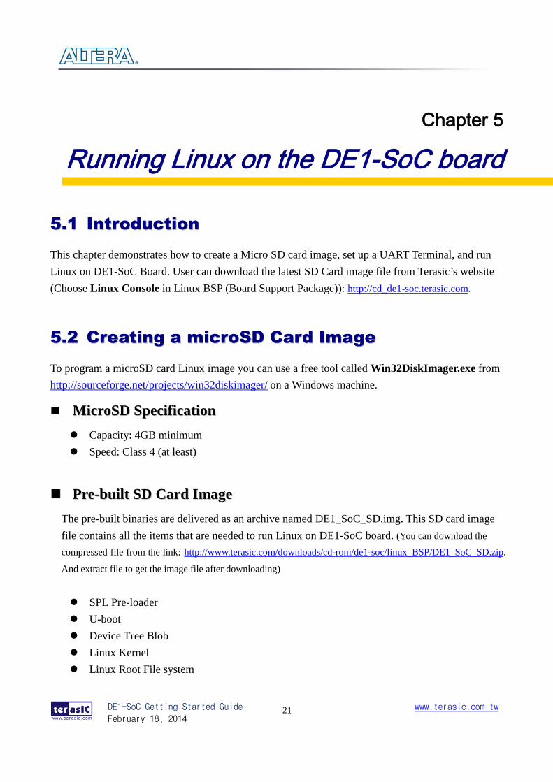
The SD card image file needs to be programmed to a microSD card before it can be used.
The steps below present how to create microSD card on a windows machine using
Win32DiskImager.exe.
1. Connect the microSD card to a Windows PC
2. Execute Win32DiskImager.exe
3. Select the image file for microSD card
4. Select the microSD card device
5. Click “write” to start writing the image file to the microSD card. Wait until the image is
written successfully.
55..33 SSeettttiinngg UUpp UUAARRTT TTeerrmmiinnaall
This section presents how to install the drivers for the USB to UART chip on the DE1-SoC board
and set up the UART terminal on your host PC. The DE1-SoC board communicates with the PC
through the micro USB connector J4.You should install the USB to UART driver and configure the
UART terminal before you run Linux on the board.
IInnssttaalllliinngg tthhee DDrriivveerr
This section presents how to install the drivers for USB to UART communication. The necessary
steps on Windows 7 are:
1. Connect your computer to the development board by plugging the USB cable into the micro
USB connector (J4) of DE1-SoC (connection shown in Figure 3-2)
DE1-SoC Getting Started Guide
February 18, 2014
www.terasic.com.tw
23
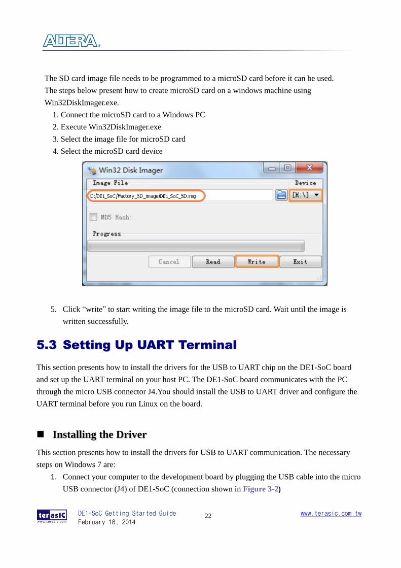
2. Power on the board then open the computer device manager in Windows. You will find an
unrecognized FT232R USB UART.
Select the FT232R USB UART to update the driver software. The driver can be downloaded from
http://www.ftdichip.com/Drivers/VCP.htm.
3. After the driver has been installed correctly, the USB Serial Port is recognized as a port such
as COM3 (Open the device manager to know which COM port assigned in your computer)
DE1-SoC Getting Started Guide
February 18, 2014
www.terasic.com.tw
24
4. Now you can power off the DE1-SoC board
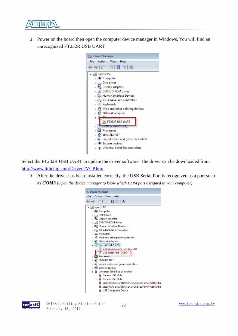
CCoonnffiigguurree UUAARRTT tteerrmmiinnaall UART terminal spec:
115200 baud rate
no parity
1 stop bit
no flow control settings
The following steps present how to configure a PuTTY terminal window (can be downloaded from
the link: http://the.earth.li/~sgtatham/putty/latest/x86/putty.exe)
1. Open putty.exe, click Serial go to a serial configure interface.
2. Configure the window like the flowing picture and click save button to save the
configuration.
DE1-SoC Getting Started Guide
February 18, 2014
www.terasic.com.tw
25
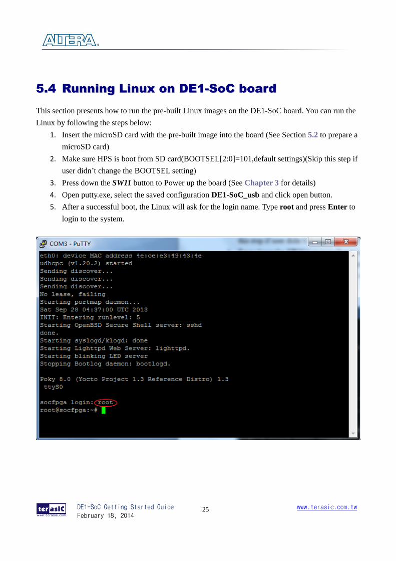
55..44 RRuunnnniinngg LLiinnuuxx oonn DDEE11--SSooCC bbooaarrdd
This section presents how to run the pre-built Linux images on the DE1-SoC board. You can run the
Linux by following the steps below:
1. Insert the microSD card with the pre-built image into the board (See Section 5.2 to prepare a
microSD card)
2. Make sure HPS is boot from SD card(BOOTSEL[2:0]=101,default settings)(Skip this step if
user didn’t change the BOOTSEL setting)
3. Press down the SW11 button to Power up the board (See Chapter 3 for details)
4. Open putty.exe, select the saved configuration DE1-SoC_usb and click open button.
5. After a successful boot, the Linux will ask for the login name. Type root and press Enter to
login to the system.
DE1-SoC Getting Started Guide
February 18, 2014
www.terasic.com.tw
26
Chapter 6
Running LXDE on the DE1-SoC board
66..11 IInnttrroodduuccttiioonn
This chapter presents how to boot LXDE Desktop on DE1-SOC board. LXDE is short for
Lightweight X11 Desktop Environment. It is an extremely fast-performing and energy-saving
desktop environment. LXDE uses less CPU and less RAM than other desktop environments. For
further information about LXDE, you can visit the website: http://LXDE.org.
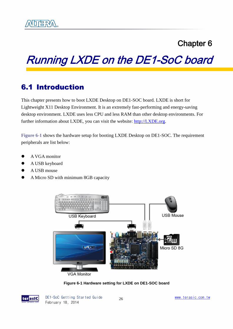
Figure 6-1 shows the hardware setup for booting LXDE Desktop on DE1-SOC. The requirement
peripherals are list below:
A VGA monitor
A USB keyboard
A USB mouse
A Micro SD with minimum 8GB capacity
Figure 6-1 Hardware setting for LXDE on DE1-SOC board
DE1-SoC Getting Started Guide
February 18, 2014
www.terasic.com.tw
27
66..22 MMaakkiinngg LLXXDDEE BBoooott SSDD CCaarrdd
To boot LXDE on DE1-SOC board user should make the boot SD card yourself. At first, user should
get the SD image from the link:
http://www.terasic.com/downloads/cd-rom/de1-soc/linux_BSP/DE1_SoC_LXDE_SD.zip.
The file you download is compressed in .zip format, so you should decompress the file after
downloading. Then you should write the image file to your boot SD card. You can refer to the
Section 5.2 for how to write the SD image in you SD card.
66..33 LLXXDDEE SSeettttiinngg UUpp PPrroocceedduurreess
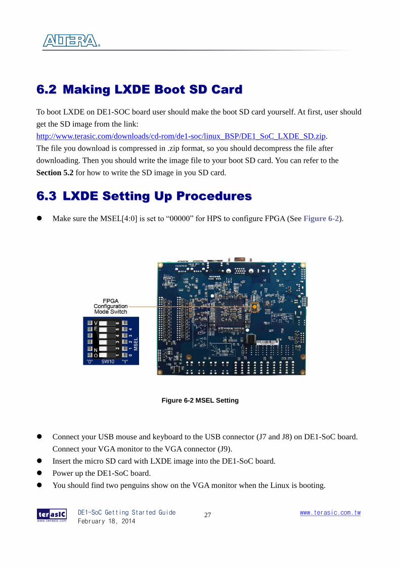
Make sure the MSEL[4:0] is set to “00000” for HPS to configure FPGA (See Figure 6-2).
Figure 6-2 MSEL Setting
Connect your USB mouse and keyboard to the USB connector (J7 and J8) on DE1-SoC board.
Connect your VGA monitor to the VGA connector (J9).
Insert the micro SD card with LXDE image into the DE1-SoC board.
Power up the DE1-SoC board.
You should find two penguins show on the VGA monitor when the Linux is booting.
DE1-SoC Getting Started Guide
February 18, 2014
www.terasic.com.tw
28
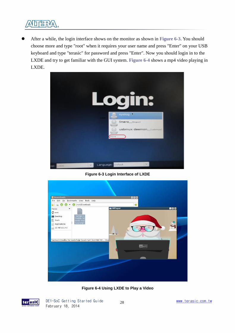
After a while, the login interface shows on the monitor as shown in Figure 6-3. You should
choose more and type "root" when it requires your user name and press "Enter" on your USB
keyboard and type "terasic" for password and press "Enter". Now you should login in to the
LXDE and try to get familiar with the GUI system. Figure 6-4 shows a mp4 video playing in
LXDE.
Figure 6-3 Login Interface of LXDE
Figure 6-4 Using LXDE to Play a Video
DE1-SoC Getting Started Guide
February 18, 2014
www.terasic.com.tw
29
Additional Information
GGeettttiinngg HHeellpp
Here are the addresses where you can get help if you encounter problems:
Terasic Technologies
9F., No.176, Sec.2, Gongdao 5th Rd, East Dist, Hsinchu City, 30070. Taiwan, 30070
Email: [email protected]
Web: 47H47Hwww.terasic.com
RReevviissiioonn HHiissttoorryy
Date Version Changes
2014.01.03 V1.0 First Version
2014.01.12 V1.1 Update ch5 for modify board rate


![DE1 SOC Introduction j.ppt [相容模式] - · PDF file• D5M specificationD5M specification-5 Mega Pixel CMOS sensor. ... Microsoft PowerPoint - DE1_SOC_Introduction_j.ppt [相容模式]](https://img.pdfslide.us/doc/110x75/5a76093b7f8b9a93088cd6c8/de1-soc-introduction-jppt-terasic-d5m-specificationd5m.jpg)