Embed Size (px)
Citation preview

De-Reverberation in Professional Audio!and Consumer Electronics
September 11, IWAENC 2014, Nice
Alexis Favrot
© Copyright Illusonic GmbH, Switzerland, 2014

De-Reverberation in Professional Audio and Consumer Electronics
IWAENC 2014
Overview!!!➤ Reverberation!!➤ De-Reverberation!!➤ Simulating A Highly Directive Microphone!!➤ De-Reverberation With Omnidirectional Microphones
© Copyright Illusonic GmbH, Switzerland, 2014

De-Reverberation in Professional Audio and Consumer Electronics
IWAENC 2014
Reverberation!!!➤ In enclosed spaces, sound energy from a source to a listening point is! ➣ partially directly transmitted! ➣ partially transmitted through reflected paths!
Source
Microphone
Direct Sound
Reflections
© Copyright Illusonic GmbH, Switzerland, 2014

De-Reverberation in Professional Audio and Consumer Electronics
IWAENC 2014
Room Impulse Response!!!!!!!!!!!!!!!➤ Late reverberation is usually considered as diffuse sound
� ⌅⇤ ⇥� ⌅⇤ ⇥�⌅⇤⇥RIR
time
DirectSound
EarlyReflections
LateReflections
© Copyright Illusonic GmbH, Switzerland, 2014

De-Reverberation in Professional Audio and Consumer Electronics
IWAENC 2014
De-Reverberation!!!➤ De-reverberation aims at attenuation of diffuse sound!!➤ Applications: capture dry speech! ➣ broadcast! ➣ ENG! ➣ film! ➣ telecommunications
© Copyright Illusonic GmbH, Switzerland, 2014

0dB
2 4 6 8
Directional ResponseShotgun
omni-directional
cardioidsub-cardioid
super-cardioid
hyper-cardioid
Directivity Index
De-Reverberation in Professional Audio and Consumer Electronics
IWAENC 2014
Conventional Microphones!!!➤ Two functional characteristics of microphones! ➣ beam-forming corresponding to the Directional Response ! ➣ de-reverberation corresponding to the Directivity Index
© Copyright Illusonic GmbH, Switzerland, 2014

030
60
90
120
150180
210
240
270
300
330 0 dB
−6 dB
−12 dB
−18 dB
0 dB
−6 dB
−12 dB
−18 dB
030
60
90
120
150180
210
240
270 300
330
030
60
90
120
150180
210
240
270
300
330 0 dB
−6 dB
−12 dB
−18 dB
0 dB
−6 dB
−12 dB
−18 dB
030
60
90
120
150180
210
240
270 300
330
0 dB
−6 dB−12 dB
−18 dB
0
30
60
90
120150
180
210
240
270
300
330
0 dB
−6 dB
−12 dB
−18 dB
030
60
90
120
150
180
210240
270
300
330
0 dB
−6 dB
−12 dB
−18 dB
030
60
90
120
150180
210
240
270
300
330
0 dB
−6 dB−12 dB
−18 dB
0
30
60
90
120150
180
210
240
270
300
330
0 dB −6
dB −12 d
B −18 d
B
030
60
90
120
150
180
210
240
270
30033
0
0 dB
−6 d
B
−12
dB
−18
dB
030
60
90
120
150
180
210
240
27030
0
330
0 dB
−6 dB
−12 d
B−1
8 dB
0
30
60
90
120
150
180
210
240
270
300
330
0 dB
−6 dB
−12 dB
−18 dB
030
60
90
120
150
180
210240
270
300
330
0 dB
−6 dB
−12 dB
−18 dB
030
60
90
120
150180
210
240
270
300
330
0 dB
−6 dB−12 dB
−18 dB
0
30
60
90
120150
180
210
240
270
300
330
0 dB−6 dB−12 dB−18 dB
030
60
90
120
150
180
210240
270
300 330
directional response directivity index
De-Reverberation in Professional Audio and Consumer Electronics
IWAENC 2014
Example 1: Omnidirectional Microphone
© Copyright Illusonic GmbH, Switzerland, 2014

030
60
90
120
150180
210
240
270
300
330 0 dB
−6 dB
−12 dB
−18 dB
030
60
90
120
150180
210
240
270
300
330 0 dB
−6 dB
−12 dB
−18 dB
0 dB
−6 dB
−12 dB
−18 dB
030
60
90
120
150180
210
240
270 300
330
0 dB
−6 dB
−12 dB
−18 dB
030
60
90
120
150180
210
240
270 300
330
0 dB
−6 dB−12 dB
−18 dB
0
30
60
90
120150
180
210
240
270
300
330
0 dB
−6 dB
−12 dB
−18 dB
030
60
90
120
150
180
210240
270
300
330
0 dB
−6 dB
−12 dB
−18 dB
030
60
90
120
150180
210
240
270
300
330
0 dB
−6 dB−12 dB
−18 dB
0
30
60
90
120150
180
210
240
270
300
330
0 dB −6
dB −12 d
B −18 d
B
030
60
90
120
150
180
210
240
270
30033
0
0 dB
−6 d
B
−12
dB
−18
dB
030
60
90
120
150
180
210
240
27030
0
330
0 dB
−6 dB
−12 d
B−1
8 dB
0
30
60
90
120
150
180
210
240
270
300
330
0 dB
−6 dB
−12 dB
−18 dB
030
60
90
120
150
180
210240
270
300
330
0 dB
−6 dB
−12 dB
−18 dB
030
60
90
120
150180
210
240
270
300
330
0 dB
−6 dB−12 dB
−18 dB
0
30
60
90
120150
180
210
240
270
300
330
0 dB−6 dB−12 dB−18 dB
030
60
90
120
150
180
210240
270
300 330
directional response directivity index
De-Reverberation in Professional Audio and Consumer Electronics
IWAENC 2014
Example 2: Cardioid Microphone
© Copyright Illusonic GmbH, Switzerland, 2014

030
60
90
120
150180
210
240
270
300
330 0 dB
−6 dB
−12 dB
−18 dB
030
60
90
120
150180
210
240
270
300
330 0 dB
−6 dB
−12 dB
−18 dB
direct only
diffuse only
De-Reverberation in Professional Audio and Consumer Electronics
IWAENC 2014
Simulating A High Directive Microphone !!➤ Digitally create a more selective microphone!!➤ Adaptive beam former with target to simulate a microphone
© Copyright Illusonic GmbH, Switzerland, 2014

De-Reverberation in Professional Audio and Consumer Electronics
IWAENC 2014
Side Lobe Canceller !!!➤ Example of a slide lobe canceller with cardioid microphones! ➣ Optimize signal to noise ratio (SNR)!!!!!!!!!!➤ Problems:! ➣ “Only one direction”! ➣ Undefined directivity index
Y = X1 � w ·X2
w =E{X1X?
2}E{X2X?
2}
030
60
90
120
150180
210
240
270
300
330 0 dB
−6 dB
−12 dB
−18 dB
Forward Cardioid X1
Backward Cardioid X2
Adaptive Beam-Former Y
© Copyright Illusonic GmbH, Switzerland, 2014

De-Reverberation in Professional Audio and Consumer Electronics
IWAENC 2014
Specification of the Directional Response!!!➤ Limiting the magnitude of the Wiener filter:!!!!!!!!!!➤ Advantages:! ➣ The width of the beam is specified
Y = X1 � g ·X2
g = min {w, g0}
Forward Cardioid X1
Backward Cardioid X2
Adaptive Beam-Former Y, g0 = 0.5
g0 = 2.0
g0 = 1
Adaptive Beam-Former Y,
Adaptive Beam-Former Y,
030
60
90
120
150180
210
240
270
300
330 0 dB
−6 dB
−12 dB
−18 dB
© Copyright Illusonic GmbH, Switzerland, 2014

Specification of the Directivity Index!!!➤ Diffuse Sound is controlled using a post-scaling factor: !! with!! from a diffuseness measure based on cross-correlation coefficients:!! ➣ Only direct sound! ➣ Only diffuse sound!
De-Reverberation in Professional Audio and Consumer Electronics
0 0.2 0.4 0.6 0.8 10
0.5
1
\12: X−correlation coeffcient
_
: diff
usen
ess
\diff
Y = c · (X1 � g ·X2) c = (1� ↵) + ↵ · c0
↵ =
1�max{�12, �di↵}1� �di↵
↵ = 0 ! c = 1↵ = 1 ! c = c0
© Copyright Illusonic GmbH, Switzerland, 2014

030
60
90
120
150180
210
240
270
300
330 0 dB
−6 dB
−12 dB
−18 dB
030
60
90
120
150180
210
240
270
300
330 0 dB
−6 dB
−12 dB
−18 dB
direct only
diffuse only
De-Reverberation in Professional Audio and Consumer Electronics
IWAENC 2014
Measurements!!!➤ Virtual measurements of the simulated microphone:
© Copyright Illusonic GmbH, Switzerland, 2014

De-Reverberation in Professional Audio and Consumer Electronics
IWAENC 2014
Time-Frequency Processing!!!➤ Taking advantage of certain independence of audio signals in the time-frequency domain:
...FB
...FB IFB...
!
+
-
y(n)
Com
puta
tion
ofan
dc
g
g0c0
Y (k, i)c(k, i)
g(k, i)X2(k, i)
X1(k, i)
x2(n)
x1(n)
© Copyright Illusonic GmbH, Switzerland, 2014

De-Reverberation in Professional Audio and Consumer Electronics
IWAENC 2014
Example: Professional Shot-Gun Microphone!!!➤ Using one shotgun + one backward cardioid!!➤ Digital Schoeps SuperCMIT microphone
Wittek et al. Digital Shotgun Microphone
• Di�use gain at low and mid frequencies isgreater than at high frequencies.
The implementation of this concept is the new mi-crophone SuperCMIT 2 U from SCHOEPS (referredto as SuperCMIT in the following), which was pre-sented and released in early 2010. It will be the ba-sis for the practical discussions and measurementsin this paper.
It is described how digital signal processing is used toimprove directivity at low frequencies, attenuate therear lobe at low frequencies, and improve (decrease)di�use gain at low and medium frequencies. The al-gorithm is an adapted and improved version of theone used by the highly directive two-cardioid-basedmicrophone system previously presented in [2]. Inorder to achieve low delay, and to avoid time or fre-quency aliasing, a non-downsampled IIR filter bankis used as time-frequency representation for the pro-cessing.
The paper is organized as follows: Section 2 de-scribes the capsule hardware and the electronic de-sign of the microphone. The signal processing, whichis applied to achieve the above-mentioned features,is described in Section 3. Evaluations and measure-ments are described in Section 4, and the conclusionsare in Section 5.
2. HARDWARE DESIGN
2.1. Capsule elementsThe SuperCMIT is a conventional shotgun micro-phone with an additional backward-facing cardioidand an integrated digital signal processor (DSP)which processes the signals of both microphone cap-sules. The two capsules are mounted nearly coinci-dently, i.e. as closely spaced as possible.
As described in [2] and specifically in Section 3, thetwo microphone elements are installed back-to-back.The interference tube acts on the first microphoneelement built in the body of the SuperCMIT. In Fig-ure 1, the interference tube and back sound entranceare visible on the right side. In the figure the micro-phone is aimed towards the right. The second micro-phone element is mounted directly behind the frontelement. This microphone element is aimed back-wards (i.e. in the figure it is aimed to the left). As
the microphone body disturbs the sound arrival atthe membrane, a large front sound entrance is usedto ensure free sound propagation up to medium-highfrequencies. The back sound entrance for the twomicrophone elements is made as short as possibleto minimize the distance between their membranes.The distance was reduced to less than 3 cm, whichmeans that for frequencies below 3 kHz the geometryis su⇤ciently coincident.
Fig. 1: Two microphone elements used in the Su-perCMIT.
The goal is to apply signal processing to both micro-phone capsules’ signals at low and medium frequen-cies. At high frequencies only the interference tubeis used. Due to this paradigm, artifacts of the adap-tive algorithm are avoided and it is not necessary tofurther reduce the distance between the microphoneelements.
2.2. Electronic designThe electronic design of the SuperCMIT circuitrycombines conventional analog condenser microphonetopologies with current digital technology to en-hance the shotgun microphone’s signal according tothe goals stated in the introduction.
The mixed-signal design is optimized for minimumclock noise interference with the analog input cir-cuitry. Both the shotgun capsule (the same asin the analog microphone CMIT 5) as well as thebackward-facing cardioid are polarized by 60 V gen-erated by a DC converter.
Both microphone capsule signals are impedance con-
AES 129th Convention, San Francisco, CA, USA, 2010 November 4–7
Page 2 of 8
Interference Tube
Forward Facing Tranducer
Backwards Facing Cardioid
© Copyright Illusonic GmbH, Switzerland, 2014

De-Reverberation in Professional Audio and Consumer Electronics
SuperCMIT Datasheet!!!➤ De-reverberation capabilities:
IWAENC 2014
© Copyright Illusonic GmbH, Switzerland, 2014

De-Reverberation in Professional Audio and Consumer Electronics
Two Omnidirectional Microphones!!!➤ The same algorithm applied to two omnidirectional microphones!!➤ Preprocessing required:
��
Delay�
�+-
d
Delay�
�+-
x1x2
h h
IWAENC 2014
© Copyright Illusonic GmbH, Switzerland, 2014

De-Reverberation in Professional Audio and Consumer Electronics
Trade Offs!!!➤ Depending on the microphone distance:! ➣ At low frequencies gain loss resulting in a SNR problem ! ➣ At high frequency, aliased frequency response
102 103 104 105−20
−15
−10
−5
0
5
10
Frequency [Hz]
[dB]
f =c
4d
IWAENC 2014
© Copyright Illusonic GmbH, Switzerland, 2014

...FB
...FB
IFB...
y(n)
Y (k, i)c(k, i)
M2(k, i)
M1(k, i)
m2(n)
m1(n)
X-correlation�12(k, i)
ReverbEstimation
FilterComputation
De-Reverberation in Professional Audio and Consumer Electronics
Alternative!!!➤ Example of a de-reverberation algorithm using two omnidirectional! microphones
IWAENC 2014
© Copyright Illusonic GmbH, Switzerland, 2014
De-Reverberation in Professional Audio and Consumer Electronics
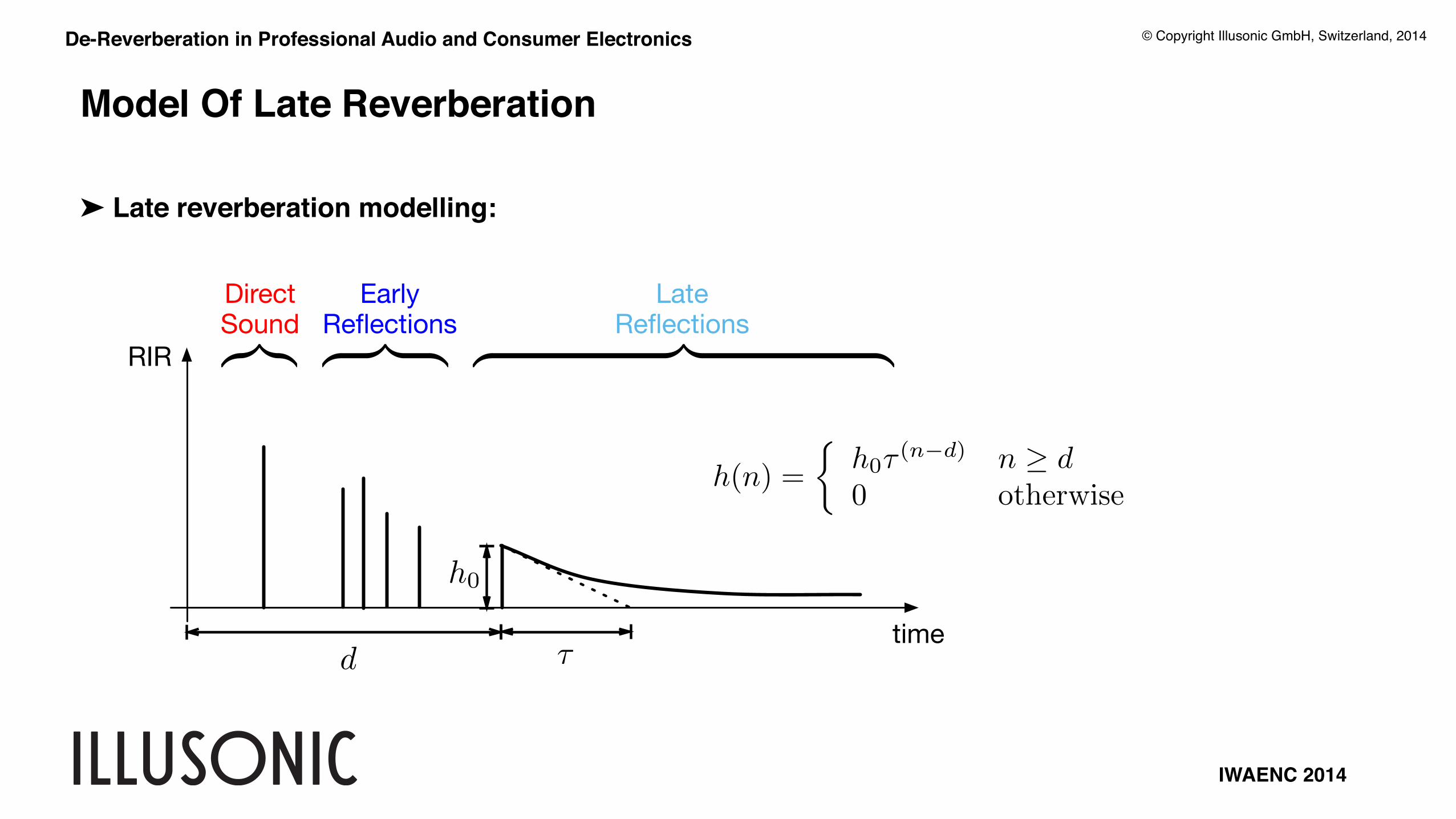
Model Of Late Reverberation!!!➤ Late reverberation modelling:
� ⌅⇤ ⇥� ⌅⇤ ⇥�⌅⇤⇥RIR
time
DirectSound
EarlyReflections
LateReflections
d
h0
⌧
h(n) =
⇢h0⌧ (n�d) n � d0 otherwise
IWAENC 2014
© Copyright Illusonic GmbH, Switzerland, 2014

...FB
IFB...
y1(n)
Reverb
Estim
ation
g(k, i)x(n)X(k, i)
Gain
Com
putation
Y (k, i)
Y (k, i)
De-Reverberation in Professional Audio and Consumer Electronics
Single Channel Block Diagram!!!➤ Example of a de-reverberation algorithm using one single microphone
IWAENC 2014
© Copyright Illusonic GmbH, Switzerland, 2014

De-Reverberation in Professional Audio and Consumer Electronics
Consumer Use Cases
IWAENC 2014
© Copyright Illusonic GmbH, Switzerland, 2014

De-Reverberation in Professional Audio and Consumer Electronics
Conclusions!!!➤ Adaptive Processing inspired from conventional directive microphones!!➤ Create high directive microphone with high de-reverberation capabilities!!➤ Use reverb model for multi- and single omnidirectional microphones
IWAENC 2014
© Copyright Illusonic GmbH, Switzerland, 2014

September 11, IWAENC 2014, Nice
© Copyright Illusonic GmbH, Switzerland, 2014
Thank you for your attention