Embed Size (px)
Citation preview

DE LORENZO S.p.A.
OIL & GAS
Petrochemical plants and machine
trainers for the Oil & Gas industry
INDEX Absorption Desorption Plant DL CH11
Combined Chemical Reactor DL CH12
Continuous Distillation DL CH13
Gas Purification DL CH14
Liquid-Liquid Extraction DL CH15
Solid-Liquid Extraction
Plant for the study of erosion-corrosion
DL CH16
DL CH17
Heat Exchangers DL PH02
Didactic Process Control Pilot Plant
Energy Efficiency Air Compressor Trainer
DL 2314BR
DL LSM-C
Bench Top Series/Parallel Pumps DL 8H402
Centrifugal Fan DL FA75
Pressure Vacuum Breaker DL OG10
Single Stage Compressor DL OG11
8 Pumps Demonstration Test Stand DL 9010
Cathodic Protection Training Bench DL MK1
Single Station Cathodic Protection Training Bench DL MK2
Oil & Gas / Chemistry
www.delorenzoglobal.com
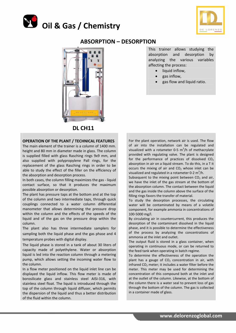
ABSORPTION – DESORPTION
DL CH11
This trainer allows studying the absorption and desorption by analyzing the various variables affecting the process:
liquid inflow,
gas inflow,
gas flow and liquid ratio.
OPERATION OF THE PLANT / TECHNICAL FEATURES The main element of the trainer is a column of 1400 mm. height and 80 mm in diameter made in glass. The column is supplied filled with glass Rasching rings 9x9 mm, and also supplied with polypropylene Pall rings, for the replacement of the glass Rasching rings in order to be able to study the effect of the filler on the efficiency of the absorption and desorption process. In both cases, the column filling maximizes the gas ‐ liquid contact surface, so that it produces the maximum possible absorption or desorption. The plant has pressure taps at the bottom and at the top of the column and two intermediate taps, through quick couplings connected to a water column differential manometer that allows determining the pressure drop within the column and the effects of the speeds of the liquid and of the gas on the pressure drop within the column. The plant also has three intermediate samplers for
sampling both the liquid phase and the gas phase and 4
temperature probes with digital display.
The liquid phase is stored in a tank of about 30 liters of capacity made of polyethylene. Water or absorption liquid is led into the reaction column through a metering pump, which allows setting the incoming water flow to the column. In a flow meter positioned on the liquid inlet line can be displayed the liquid inflow. This flow meter is made of borosilicate glass and stainless steel AISI‐316, with stainless steel float. The liquid is introduced through the top of the column through liquid diffuser, which permits the dispersion of the liquid and thus a better distribution of the fluid within the column.
For the plant operation, network air is used. The flow of air into the installation can be regulated and visualized with a rotameter 0‐5 m3/h of methacrylate provided with regulating valve. The plant is designed for the performance of practices of dissolved CO2 absorption in air on a liquid stream. To do this, in a T it occurs the mixing of air and CO2 whose inlet can be visualized and regulated in a rotameter 0‐2 m3/h. Subsequent to the mixing point between CO2 and air, we have the inlet of the gas stream at the bottom of the absorption column. The contact between the liquid and the gas inside the column above the surface of the filling rings favors the transfer of material. To study the desorption processes, the circulating water will be contaminated by means of a volatile component, for example ammonia in concentrations of 100‐5000 mg/l. By circulating air in countercurrent, this produces the desorption of the contaminant dissolved in the liquid phase, and it is possible to determine the effectiveness of the process by analyzing the concentrations of ammonia at the inlet and outlet. The output fluid is stored in a glass container, when operating in continuous mode, or can be returned to the feed tank when operating in batch regime. To determine the effectiveness of the operation the plant has a gauge of CO2 concentration in air, with infrared CO2 meter; it includes a water filter before the meter. This meter may be used for determining the concentration of this compound both at the inlet and at the outlet of the column. Likewise, at the bottom of the column there is a water seal to prevent loss of gas through the bottom of the column. The gas is collected in a container made of glass.
Oil & Gas / Chemistry
www.delorenzoglobal.com
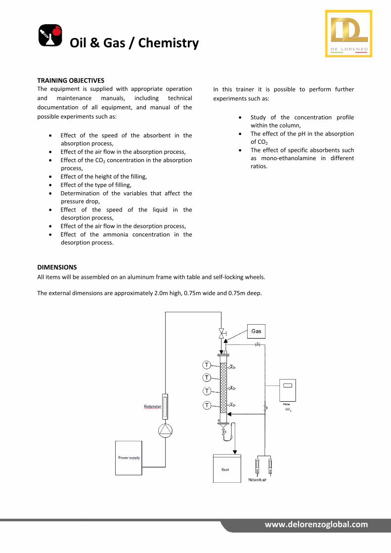
DIMENSIONS
All items will be assembled on an aluminum frame with table and self‐locking wheels. The external dimensions are approximately 2.0m high, 0.75m wide and 0.75m deep.
TRAINING OBJECTIVES The equipment is supplied with appropriate operation
and maintenance manuals, including technical
documentation of all equipment, and manual of the
possible experiments such as:
Effect of the speed of the absorbent in the absorption process,
Effect of the air flow in the absorption process,
Effect of the CO2 concentration in the absorption process,
Effect of the height of the filling,
Effect of the type of filling,
Determination of the variables that affect the pressure drop,
Effect of the speed of the liquid in the desorption process,
Effect of the air flow in the desorption process,
Effect of the ammonia concentration in the desorption process.
In this trainer it is possible to perform further
experiments such as:
Study of the concentration profile within the column,
The effect of the pH in the absorption of CO2
The effect of specific absorbents such as mono‐ethanolamine in different ratios.
Oil & Gas / Chemistry
www.delorenzoglobal.com
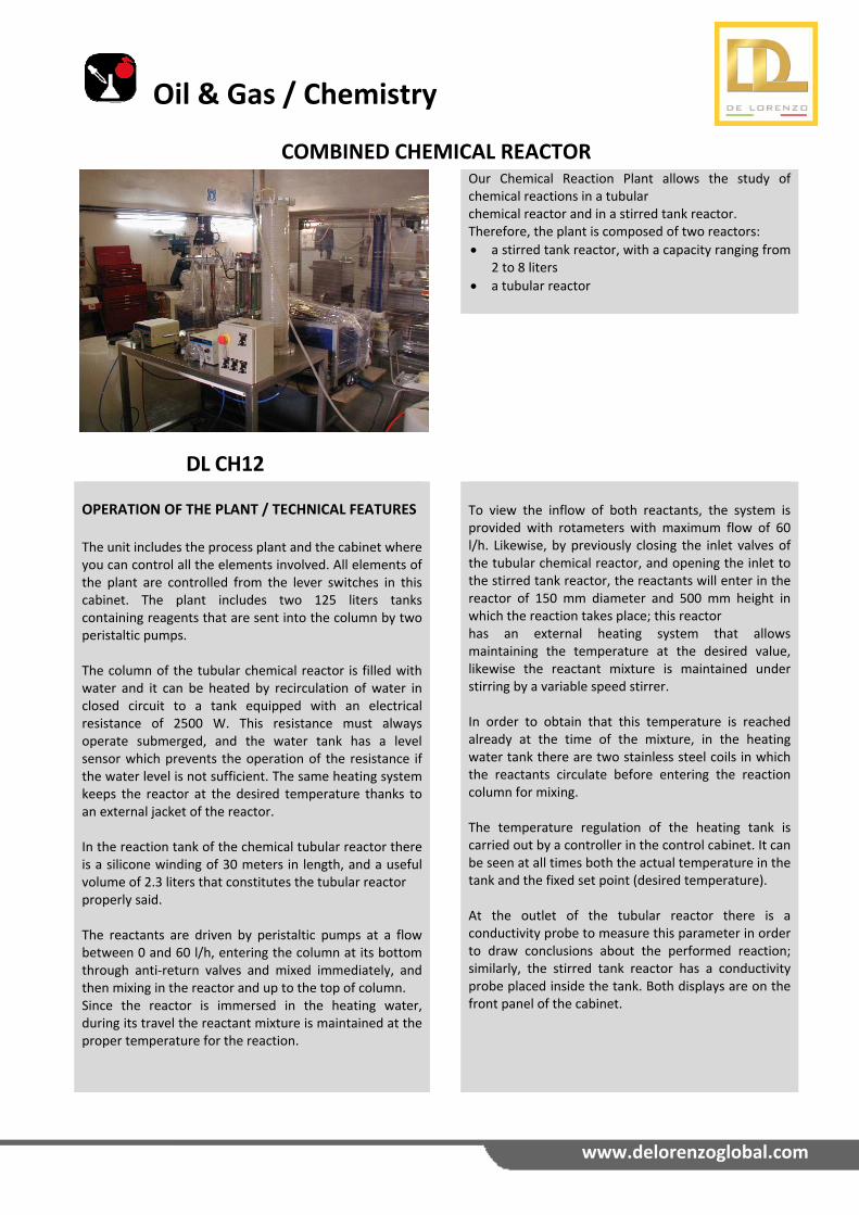
COMBINED CHEMICAL REACTOR
DL CH12
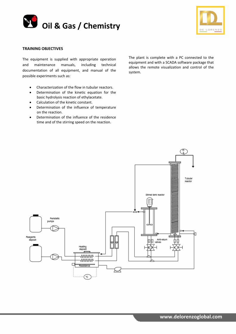
Our Chemical Reaction Plant allows the study of chemical reactions in a tubular chemical reactor and in a stirred tank reactor. Therefore, the plant is composed of two reactors:
a stirred tank reactor, with a capacity ranging from 2 to 8 liters
a tubular reactor
OPERATION OF THE PLANT / TECHNICAL FEATURES The unit includes the process plant and the cabinet where you can control all the elements involved. All elements of the plant are controlled from the lever switches in this cabinet. The plant includes two 125 liters tanks containing reagents that are sent into the column by two peristaltic pumps. The column of the tubular chemical reactor is filled with water and it can be heated by recirculation of water in closed circuit to a tank equipped with an electrical resistance of 2500 W. This resistance must always operate submerged, and the water tank has a level sensor which prevents the operation of the resistance if the water level is not sufficient. The same heating system keeps the reactor at the desired temperature thanks to an external jacket of the reactor. In the reaction tank of the chemical tubular reactor there is a silicone winding of 30 meters in length, and a useful volume of 2.3 liters that constitutes the tubular reactor properly said. The reactants are driven by peristaltic pumps at a flow between 0 and 60 l/h, entering the column at its bottom through anti‐return valves and mixed immediately, and then mixing in the reactor and up to the top of column. Since the reactor is immersed in the heating water, during its travel the reactant mixture is maintained at the proper temperature for the reaction.
To view the inflow of both reactants, the system is provided with rotameters with maximum flow of 60 l/h. Likewise, by previously closing the inlet valves of the tubular chemical reactor, and opening the inlet to the stirred tank reactor, the reactants will enter in the reactor of 150 mm diameter and 500 mm height in which the reaction takes place; this reactor has an external heating system that allows maintaining the temperature at the desired value, likewise the reactant mixture is maintained under stirring by a variable speed stirrer. In order to obtain that this temperature is reached already at the time of the mixture, in the heating water tank there are two stainless steel coils in which the reactants circulate before entering the reaction column for mixing. The temperature regulation of the heating tank is carried out by a controller in the control cabinet. It can be seen at all times both the actual temperature in the tank and the fixed set point (desired temperature). At the outlet of the tubular reactor there is a conductivity probe to measure this parameter in order to draw conclusions about the performed reaction; similarly, the stirred tank reactor has a conductivity probe placed inside the tank. Both displays are on the front panel of the cabinet.
Oil & Gas / Chemistry
www.delorenzoglobal.com
TRAINING OBJECTIVES
The equipment is supplied with appropriate operation
and maintenance manuals, including technical
documentation of all equipment, and manual of the
possible experiments such as:
Characterization of the flow in tubular reactors.
Determination of the kinetic equation for the basic hydrolysis reaction of ethylacetate.
Calculation of the kinetic constant.
Determination of the influence of temperature on the reaction.
Determination of the influence of the residence time and of the stirring speed on the reaction.
The plant is complete with a PC connected to the equipment and with a SCADA software package that allows the remote visualization and control of the system.
Oil & Gas / Chemistry
www.delorenzoglobal.com
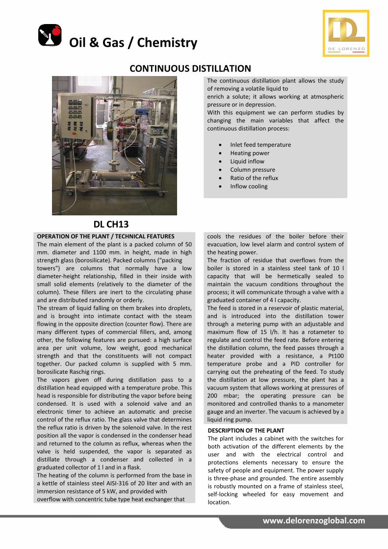
CONTINUOUS DISTILLATION
DL CH13
The continuous distillation plant allows the study of removing a volatile liquid to enrich a solute; it allows working at atmospheric pressure or in depression. With this equipment we can perform studies by changing the main variables that affect the continuous distillation process:
Inlet feed temperature
Heating power
Liquid inflow
Column pressure
Ratio of the reflux
Inflow cooling
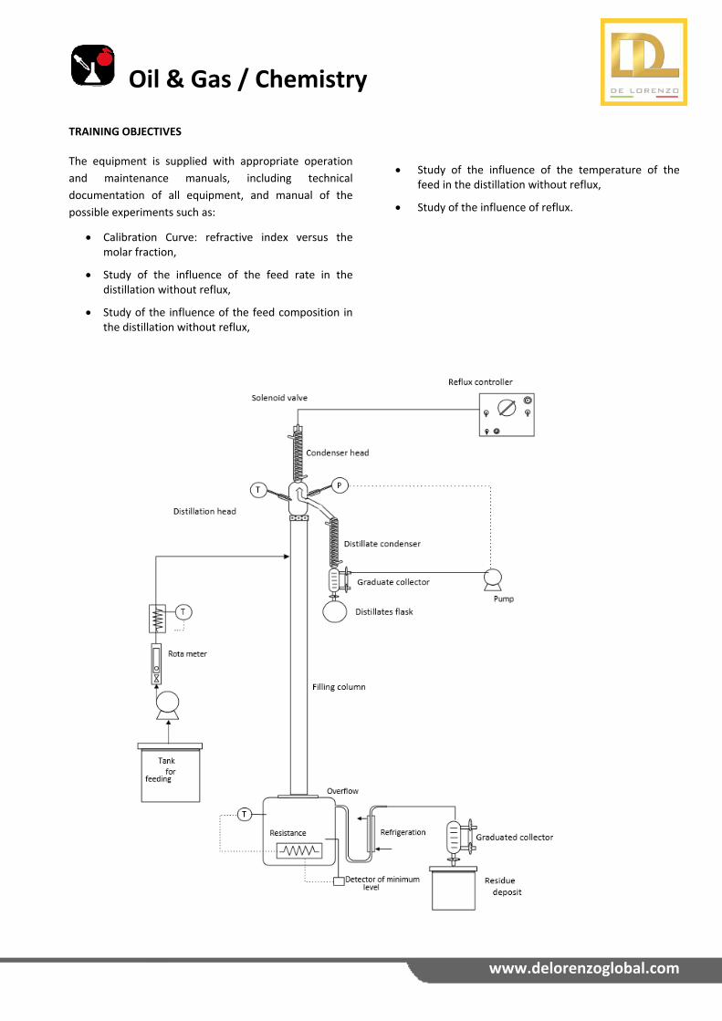
OPERATION OF THE PLANT / TECHNICAL FEATURESThe main element of the plant is a packed column of 50 mm. diameter and 1100 mm. in height, made in high strength glass (borosilicate). Packed columns ("packing towers") are columns that normally have a low diameter‐height relationship, filled in their inside with small solid elements (relatively to the diameter of the column). These fillers are inert to the circulating phase and are distributed randomly or orderly. The stream of liquid falling on them brakes into droplets, and is brought into intimate contact with the steam flowing in the opposite direction (counter flow). There are many different types of commercial fillers, and, among other, the following features are pursued: a high surface area per unit volume, low weight, good mechanical strength and that the constituents will not compact together. Our packed column is supplied with 5 mm. borosilicate Raschig rings. The vapors given off during distillation pass to a distillation head equipped with a temperature probe. This head is responsible for distributing the vapor before being condensed. It is used with a solenoid valve and an electronic timer to achieve an automatic and precise control of the reflux ratio. The glass valve that determines the reflux ratio is driven by the solenoid valve. In the rest position all the vapor is condensed in the condenser head and returned to the column as reflux, whereas when the valve is held suspended, the vapor is separated as distillate through a condenser and collected in a graduated collector of 1 l and in a flask. The heating of the column is performed from the base in a kettle of stainless steel AISI‐316 of 20 liter and with an immersion resistance of 5 kW, and provided with overflow with concentric tube type heat exchanger that
cools the residues of the boiler before their evacuation, low level alarm and control system of the heating power. The fraction of residue that overflows from the boiler is stored in a stainless steel tank of 10 l capacity that will be hermetically sealed to maintain the vacuum conditions throughout the process; it will communicate through a valve with a graduated container of 4 l capacity. The feed is stored in a reservoir of plastic material, and is introduced into the distillation tower through a metering pump with an adjustable and maximum flow of 15 l/h. It has a rotameter to regulate and control the feed rate. Before entering the distillation column, the feed passes through a heater provided with a resistance, a Pt100 temperature probe and a PID controller for carrying out the preheating of the feed. To study the distillation at low pressure, the plant has a vacuum system that allows working at pressures of 200 mbar; the operating pressure can be monitored and controlled thanks to a manometer gauge and an inverter. The vacuum is achieved by a liquid ring pump. DESCRIPTION OF THE PLANT The plant includes a cabinet with the switches for both activation of the different elements by the user and with the electrical control and protections elements necessary to ensure the safety of people and equipment. The power supply is three‐phase and grounded. The entire assembly is robustly mounted on a frame of stainless steel, self‐locking wheeled for easy movement and location.
Oil & Gas / Chemistry
www.delorenzoglobal.com
Study of the influence of the temperature of the feed in the distillation without reflux,
Study of the influence of reflux.
TRAINING OBJECTIVES The equipment is supplied with appropriate operation
and maintenance manuals, including technical
documentation of all equipment, and manual of the
possible experiments such as:
Calibration Curve: refractive index versus the molar fraction,
Study of the influence of the feed rate in the distillation without reflux,
Study of the influence of the feed composition in the distillation without reflux,
Oil & Gas / Chemistry
www.delorenzoglobal.com
GAS PURIFICATION
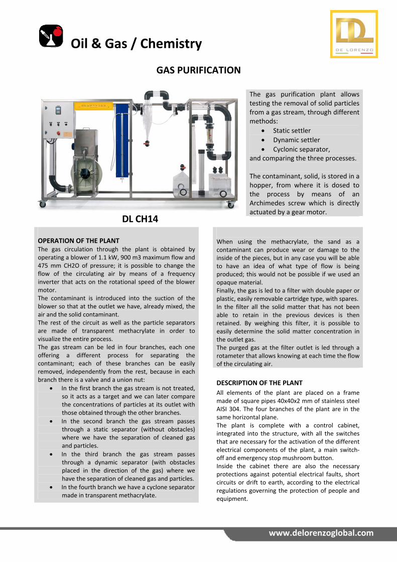
DL CH14
The gas purification plant allows testing the removal of solid particles from a gas stream, through different methods:
Static settler
Dynamic settler
Cyclonic separator, and comparing the three processes. The contaminant, solid, is stored in a hopper, from where it is dosed to the process by means of an Archimedes screw which is directly actuated by a gear motor.
OPERATION OF THE PLANT The gas circulation through the plant is obtained by operating a blower of 1.1 kW, 900 m3 maximum flow and 475 mm CH2O of pressure; it is possible to change the flow of the circulating air by means of a frequency inverter that acts on the rotational speed of the blower motor. The contaminant is introduced into the suction of the blower so that at the outlet we have, already mixed, the air and the solid contaminant. The rest of the circuit as well as the particle separators are made of transparent methacrylate in order to visualize the entire process. The gas stream can be led in four branches, each one offering a different process for separating the contaminant; each of these branches can be easily removed, independently from the rest, because in each branch there is a valve and a union nut:
In the first branch the gas stream is not treated, so it acts as a target and we can later compare the concentrations of particles at its outlet with those obtained through the other branches.
In the second branch the gas stream passes through a static separator (without obstacles) where we have the separation of cleaned gas and particles.
In the third branch the gas stream passes through a dynamic separator (with obstacles placed in the direction of the gas) where we have the separation of cleaned gas and particles.
In the fourth branch we have a cyclone separator made in transparent methacrylate.
When using the methacrylate, the sand as a contaminant can produce wear or damage to the inside of the pieces, but in any case you will be able to have an idea of what type of flow is being produced; this would not be possible if we used an opaque material. Finally, the gas is led to a filter with double paper or plastic, easily removable cartridge type, with spares. In the filter all the solid matter that has not been able to retain in the previous devices is then retained. By weighing this filter, it is possible to easily determine the solid matter concentration in the outlet gas. The purged gas at the filter outlet is led through a rotameter that allows knowing at each time the flow of the circulating air.
DESCRIPTION OF THE PLANT
All elements of the plant are placed on a frame made of square pipes 40x40x2 mm of stainless steel AISI 304. The four branches of the plant are in the same horizontal plane. The plant is complete with a control cabinet, integrated into the structure, with all the switches that are necessary for the activation of the different electrical components of the plant, a main switch‐off and emergency stop mushroom button. Inside the cabinet there are also the necessary protections against potential electrical faults, short circuits or drift to earth, according to the electrical regulations governing the protection of people and equipment.
Oil & Gas / Chemistry
www.delorenzoglobal.com
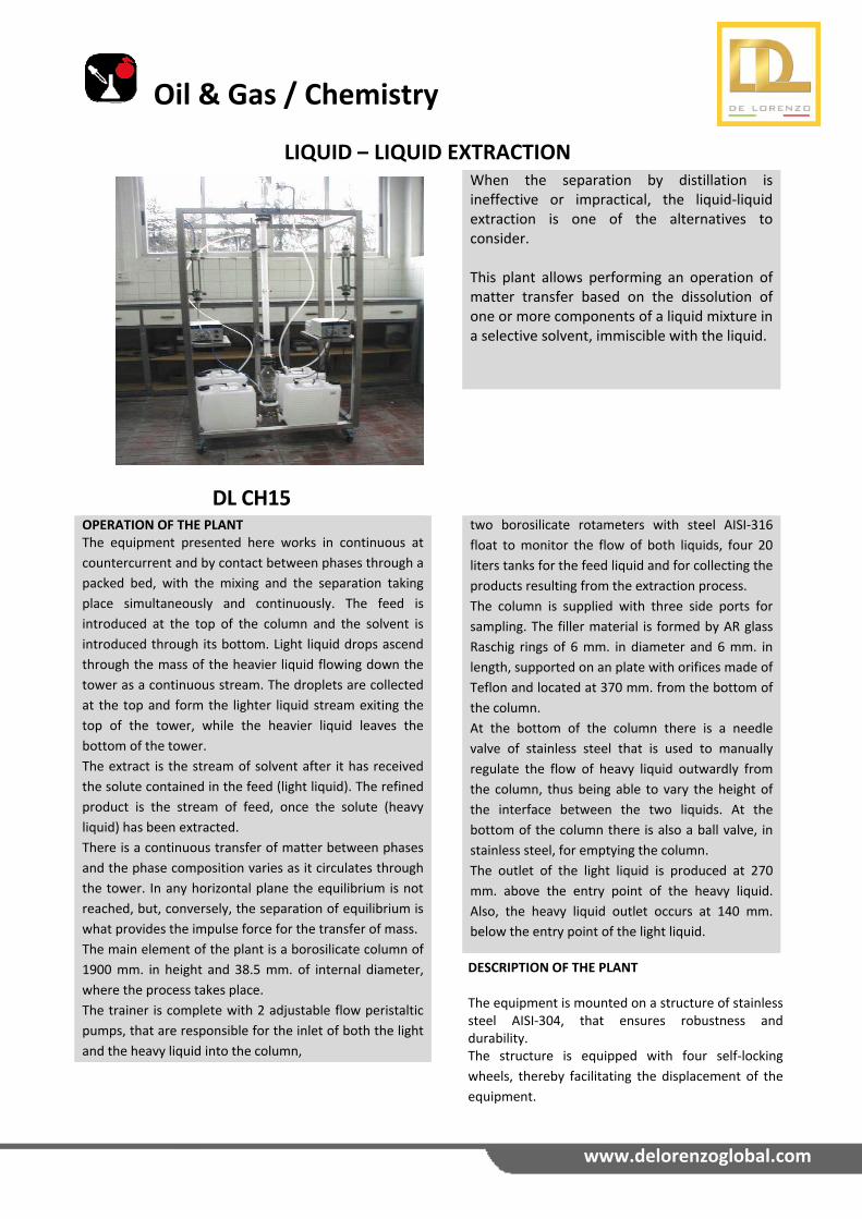
LIQUID – LIQUID EXTRACTION
DL CH15
When the separation by distillation is ineffective or impractical, the liquid‐liquid extraction is one of the alternatives to consider. This plant allows performing an operation of matter transfer based on the dissolution of one or more components of a liquid mixture in a selective solvent, immiscible with the liquid.
OPERATION OF THE PLANT The equipment presented here works in continuous at
countercurrent and by contact between phases through a
packed bed, with the mixing and the separation taking
place simultaneously and continuously. The feed is
introduced at the top of the column and the solvent is
introduced through its bottom. Light liquid drops ascend
through the mass of the heavier liquid flowing down the
tower as a continuous stream. The droplets are collected
at the top and form the lighter liquid stream exiting the
top of the tower, while the heavier liquid leaves the
bottom of the tower.
The extract is the stream of solvent after it has received
the solute contained in the feed (light liquid). The refined
product is the stream of feed, once the solute (heavy
liquid) has been extracted.
There is a continuous transfer of matter between phases
and the phase composition varies as it circulates through
the tower. In any horizontal plane the equilibrium is not
reached, but, conversely, the separation of equilibrium is
what provides the impulse force for the transfer of mass.
The main element of the plant is a borosilicate column of
1900 mm. in height and 38.5 mm. of internal diameter,
where the process takes place.
The trainer is complete with 2 adjustable flow peristaltic
pumps, that are responsible for the inlet of both the light
and the heavy liquid into the column,
two borosilicate rotameters with steel AISI‐316
float to monitor the flow of both liquids, four 20
liters tanks for the feed liquid and for collecting the
products resulting from the extraction process.
The column is supplied with three side ports for
sampling. The filler material is formed by AR glass
Raschig rings of 6 mm. in diameter and 6 mm. in
length, supported on an plate with orifices made of
Teflon and located at 370 mm. from the bottom of
the column.
At the bottom of the column there is a needle
valve of stainless steel that is used to manually
regulate the flow of heavy liquid outwardly from
the column, thus being able to vary the height of
the interface between the two liquids. At the
bottom of the column there is also a ball valve, in
stainless steel, for emptying the column.
The outlet of the light liquid is produced at 270
mm. above the entry point of the heavy liquid.
Also, the heavy liquid outlet occurs at 140 mm.
below the entry point of the light liquid.
DESCRIPTION OF THE PLANT The equipment is mounted on a structure of stainless steel AISI‐304, that ensures robustness and durability. The structure is equipped with four self‐locking
wheels, thereby facilitating the displacement of the
equipment.
Oil & Gas / Chemistry
www.delorenzoglobal.com
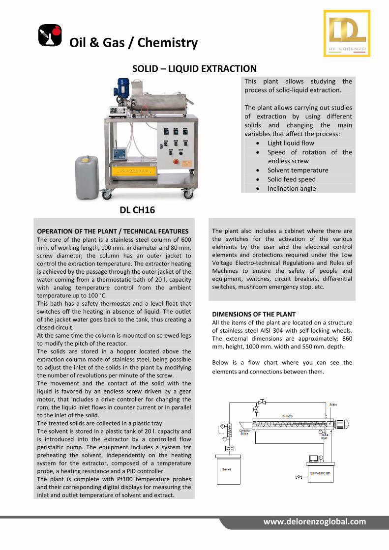
SOLID – LIQUID EXTRACTION
DL CH16
This plant allows studying the process of solid‐liquid extraction. The plant allows carrying out studies of extraction by using different solids and changing the main variables that affect the process:
Light liquid flow
Speed of rotation of the endless screw
Solvent temperature
Solid feed speed
Inclination angle
OPERATION OF THE PLANT / TECHNICAL FEATURES The core of the plant is a stainless steel column of 600 mm. of working length, 100 mm. in diameter and 80 mm. screw diameter; the column has an outer jacket to control the extraction temperature. The extractor heating is achieved by the passage through the outer jacket of the water coming from a thermostatic bath of 20 l. capacity with analog temperature control from the ambient temperature up to 100 °C. This bath has a safety thermostat and a level float that switches off the heating in absence of liquid. The outlet of the jacket water goes back to the tank, thus creating a closed circuit. At the same time the column is mounted on screwed legs to modify the pitch of the reactor. The solids are stored in a hopper located above the extraction column made of stainless steel, being possible to adjust the inlet of the solids in the plant by modifying the number of revolutions per minute of the screw. The movement and the contact of the solid with the liquid is favored by an endless screw driven by a gear motor, that includes a drive controller for changing the rpm; the liquid inlet flows in counter current or in parallel to the inlet of the solid. The treated solids are collected in a plastic tray. The solvent is stored in a plastic tank of 20 l. capacity and is introduced into the extractor by a controlled flow peristaltic pump. The equipment includes a system for preheating the solvent, independently on the heating system for the extractor, composed of a temperature probe, a heating resistance and a PID controller. The plant is complete with Pt100 temperature probes and their corresponding digital displays for measuring the inlet and outlet temperature of solvent and extract.
The plant also includes a cabinet where there are the switches for the activation of the various elements by the user and the electrical control elements and protections required under the Low Voltage Electro‐technical Regulations and Rules of Machines to ensure the safety of people and equipment, switches, circuit breakers, differential switches, mushroom emergency stop, etc.
DIMENSIONS OF THE PLANT All the items of the plant are located on a structure of stainless steel AISI 304 with self‐locking wheels. The external dimensions are approximately: 860 mm. height, 1000 mm. width and 550 mm. depth. Below is a flow chart where you can see the
elements and connections between them.
Oil & Gas / Chemistry
www.delorenzoglobal.com
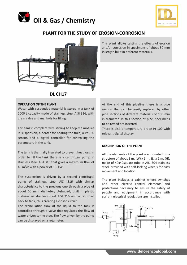
PLANT FOR THE STUDY OF EROSION‐CORROSION
DL CH17
This plant allows testing the effects of erosion and/or corrosion in specimens of about 50 mm in length built in different materials.
OPERATION OF THE PLANT Water with suspended material is stored in a tank of
1000 L capacity made of stainless steel AISI 316, with
drain valve and manhole for filling.
This tank is complete with stirring to keep the mixture
in suspension, a heater for heating the fluid, a Pt‐100
sensor, and a digital controller for controlling the
parameters in the tank.
The tank is thermally insulated to prevent heat loss. In
order to fill the tank there is a centrifugal pump in
stainless steel AISI 316 that gives a maximum flow of
45 m3/h with a power of 1.5 kW.
The suspension is driven by a second centrifugal
pump of stainless steel AISI 316 with similar
characteristics to the previous one through a pipe of
about 65 mm. diameter, U‐shaped, built in plastic
material or stainless steel AISI 316 and is returned
back to tank, thus creating a closed circuit.
The recirculation flow of the liquid to the tank is
controlled through a valve that regulates the flow of
water driven to the pipe. The flow driven by the pump
can be displayed on a rotameter.
At the end of this pipeline there is a pipe
section that can be easily replaced by other
pipe sections of different materials of 150 mm
in diameter. In this section of pipe, specimens
to be tested are inserted.
There is also a temperature probe Pt‐100 with
relevant digital display.
DESCRIPTION OF THE PLANT All the elements of the plant are mounted on a structure of about 1 m. (W) x 3 m. (L) x 1 m. (H), made of 40x40square tube in AISI 304 stainless steel, provided with self‐locking wheels for easy movement and location. The plant includes a cabinet where switches and other electric control elements and protections necessary to ensure the safety of people and equipment in accordance with current electrical regulations are installed.
Oil & Gas / Chemistry
www.delorenzoglobal.com
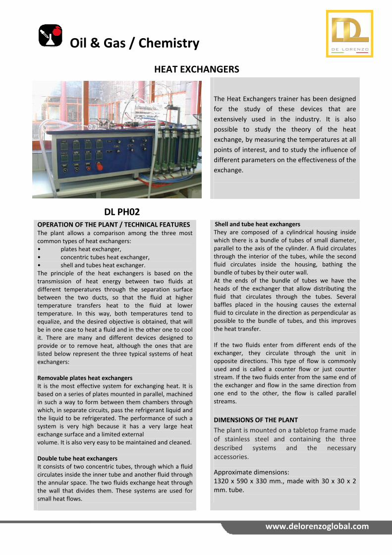
HEAT EXCHANGERS
DL PH02
The Heat Exchangers trainer has been designed
for the study of these devices that are
extensively used in the industry. It is also
possible to study the theory of the heat
exchange, by measuring the temperatures at all
points of interest, and to study the influence of
different parameters on the effectiveness of the
exchange.
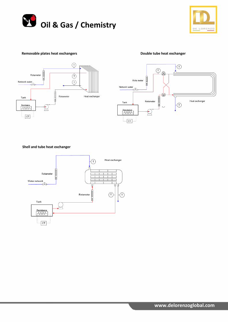
OPERATION OF THE PLANT / TECHNICAL FEATURES The plant allows a comparison among the three most common types of heat exchangers: • plates heat exchanger, • concentric tubes heat exchanger, • shell and tubes heat exchanger. The principle of the heat exchangers is based on the transmission of heat energy between two fluids at different temperatures through the separation surface between the two ducts, so that the fluid at higher temperature transfers heat to the fluid at lower temperature. In this way, both temperatures tend to equalize, and the desired objective is obtained, that will be in one case to heat a fluid and in the other one to cool it. There are many and different devices designed to provide or to remove heat, although the ones that are listed below represent the three typical systems of heat exchangers: Removable plates heat exchangers It is the most effective system for exchanging heat. It is based on a series of plates mounted in parallel, machined in such a way to form between them chambers through which, in separate circuits, pass the refrigerant liquid and the liquid to be refrigerated. The performance of such a system is very high because it has a very large heat exchange surface and a limited external volume. It is also very easy to be maintained and cleaned. Double tube heat exchangers It consists of two concentric tubes, through which a fluid circulates inside the inner tube and another fluid through the annular space. The two fluids exchange heat through the wall that divides them. These systems are used for small heat flows.
Shell and tube heat exchangers They are composed of a cylindrical housing inside which there is a bundle of tubes of small diameter, parallel to the axis of the cylinder. A fluid circulates through the interior of the tubes, while the second fluid circulates inside the housing, bathing the bundle of tubes by their outer wall. At the ends of the bundle of tubes we have the heads of the exchanger that allow distributing the fluid that circulates through the tubes. Several baffles placed in the housing causes the external fluid to circulate in the direction as perpendicular as possible to the bundle of tubes, and this improves the heat transfer. If the two fluids enter from different ends of the exchanger, they circulate through the unit in opposite directions. This type of flow is commonly used and is called a counter flow or just counter stream. If the two fluids enter from the same end of the exchanger and flow in the same direction from one end to the other, the flow is called parallel streams.
DIMENSIONS OF THE PLANT The plant is mounted on a tabletop frame made of stainless steel and containing the three described systems and the necessary accessories.
Approximate dimensions: 1320 x 590 x 330 mm., made with 30 x 30 x 2 mm. tube.
Oil & Gas / Chemistry
www.delorenzoglobal.com
Removable plates heat exchangers Shell and tube heat exchanger
Double tube heat exchanger
AUTOMATION
www.delorenzoglobal.com
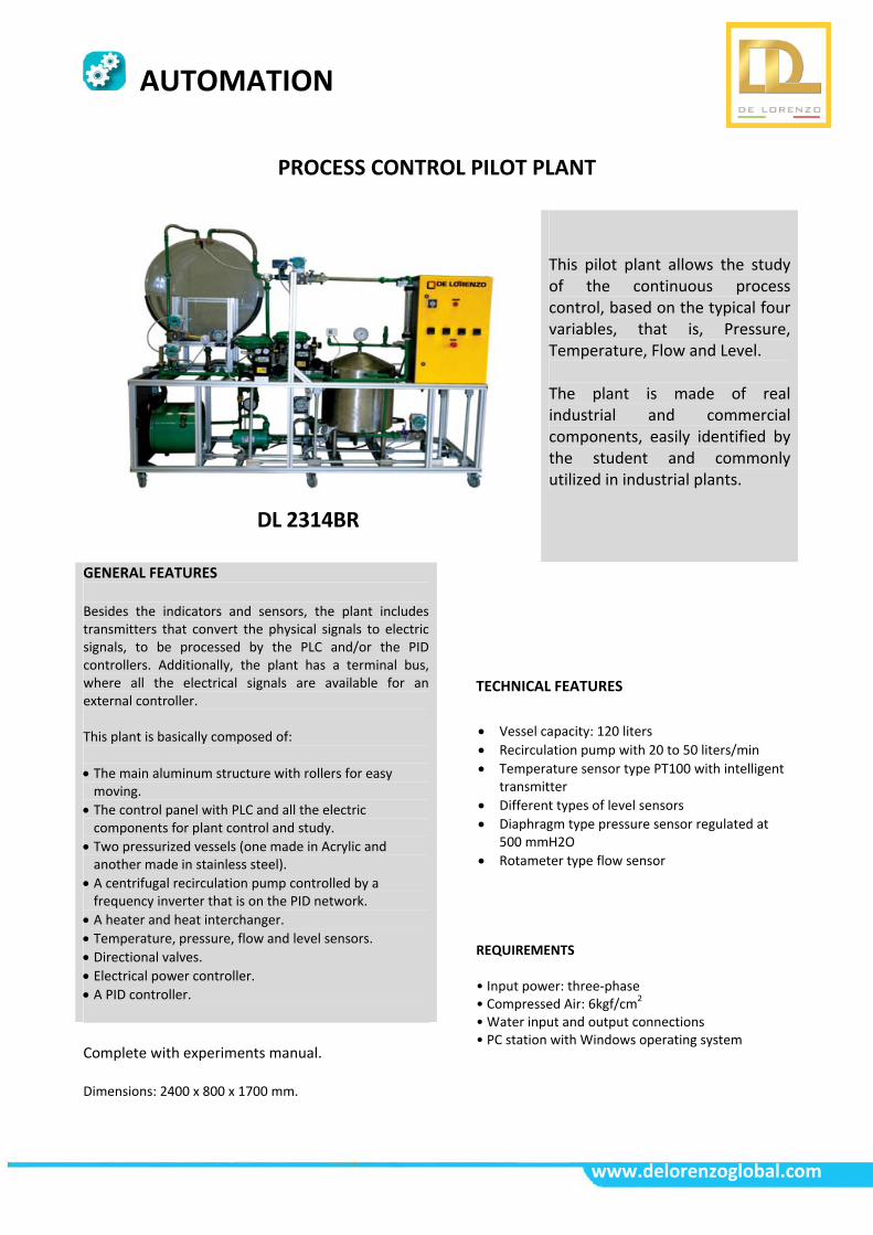
PROCESS CONTROL PILOT PLANT
DL 2314BR
This pilot plant allows the study of the continuous process control, based on the typical four variables, that is, Pressure, Temperature, Flow and Level. The plant is made of real industrial and commercial components, easily identified by the student and commonly utilized in industrial plants.
GENERAL FEATURES Besides the indicators and sensors, the plant includes transmitters that convert the physical signals to electric signals, to be processed by the PLC and/or the PID controllers. Additionally, the plant has a terminal bus, where all the electrical signals are available for an external controller. This plant is basically composed of:
The main aluminum structure with rollers for easy moving.
The control panel with PLC and all the electric components for plant control and study.
Two pressurized vessels (one made in Acrylic and another made in stainless steel).
A centrifugal recirculation pump controlled by a frequency inverter that is on the PID network.
A heater and heat interchanger. Temperature, pressure, flow and level sensors.
Directional valves. Electrical power controller. A PID controller.
TECHNICAL FEATURES
Vessel capacity: 120 liters
Recirculation pump with 20 to 50 liters/min
Temperature sensor type PT100 with intelligent transmitter
Different types of level sensors
Diaphragm type pressure sensor regulated at 500 mmH2O
Rotameter type flow sensor
REQUIREMENTS • Input power: three‐phase • Compressed Air: 6kgf/cm2 • Water input and output connections • PC station with Windows operating system
Complete with experiments manual. Dimensions: 2400 x 800 x 1700 mm.
ENERGY EFFICIENCY
www.delorenzoglobal.com
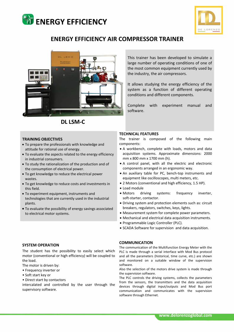
ENERGY EFFICIENCY AIR COMPRESSOR TRAINER
DL LSM‐C
This trainer has been developed to simulate a large number of operating conditions of one of the most common equipment currently used by the industry, the air compressors. It allows studying the energy efficiency of the system as a function of different operating conditions and different components. Complete with experiment manual and software.
TRAINING OBJECTIVES To prepare the professionals with knowledge and attitude for rational use of energy.
To evaluate the aspects related to the energy efficiency in industrial consumers.
To study the rationalization of the production and of the consumption of electrical power.
To get knowledge to reduce the electrical power wastes.
To get knowledge to reduce costs and investments in this field.
To experiment equipment, instruments and technologies that are currently used in the industrial plants.
To evaluate the possibility of energy savings associated to electrical motor systems.
TECHNICAL FEATURES The trainer is composed of the following main components:
A workbench, complete with loads, motors and data acquisition systems. Approximate dimensions: 2000 mm x 800 mm x 1700 mm (h).
A control panel, with all the electric and electronic components arranged in an ergonomic way.
An auxiliary table for PC, bench‐top instruments and equipment like oscilloscopes, multi meters, etc.
2 Motors (conventional and high efficiency, 1.5 HP).
Load module
Motors driving systems: frequency inverter, soft‐starter, contactor.
Driving system and protection elements such as: circuit breakers, regulators, switches, keys, lights.
Measurement system for complete power parameters.
Mechanical and electrical data acquisition instruments.
Programmable Logic Controller (PLC).
SCADA Software for supervision and data acquisition.
COMMUNICATION The communication of the Multifunction Energy Meter with the PLC is made through a serial interface with Mod Bus protocol and all the parameters (historical, time curve, etc.) are shown and monitored on a suitable window of the supervision software. Also the selection of the motors drive system is made through the supervision software. The PLC controls the driving systems, collects the parameters from the sensors, the transmitters and the data acquisition devices through digital input/outputs and Mod Bus port communication and communicates with the supervision software through Ethernet.
SYSTEM OPERATION
The student has the possibility to easily select which motor (conventional or high efficiency) will be coupled to the load. The motor is driven by: • Frequency inverter or • Soft start key or • Direct start by contactors intercalated and controlled by the user through the supervisory software.
ENERGY EFFICIENCY
www.delorenzoglobal.com
LIST OF EXPERIMENTS It is possible to perform a large number of practical experiments such as:
Study of the energy efficiency of the motors for a 0 to 120% variation of the load.
Study of energy efficiency of the motors as a function of the use of the frequency inverter application, through the variation of the speed of the motor‐load combination.
Generation of the characteristic curves of the main devices (electrical and mechanical parameters, pumps, fans, etc.).
Generation of the characteristic curves of the motors (conventional and high efficiency).
Comparison of the electrical and mechanical values from direct driving, soft start and frequency inverter as a function of the variation of the load.
Comparison of the consumption of energy for different configurations and types of devices.
Analysis of the energy efficiency considering different setups in the coupling between the motor and the load.
TECHNICAL CHARACTERISTICS The load system of this bench is composed of a two piston air compressor, with 1.5 HP motor capacity. The air compressed tank has a capacity of up to 40 liters, regulated by an electric valve that controls the air pressure of the tank through the supervision software. Additionally, the tank has a safety valve specified in agreement with the conditions of the tank’s capabilities. The coupling of the motors with the compressor is made of pulleys and belts in "V” shape. The air piping allows the simulation of the load losses through holes of different diameters (5 holes), selected by solenoid type valves and activated by the supervision software. 5 different loads can be adjusted according to the experimental needs timely. The location of these holes allows the measurement of these losses. The load allows a variation, controlled by the supervision software, from 0 to 120% of the nominal load of the motor. Each motor (conventional and of high‐efficiency) has a PT‐100 temperature sensor in the carcass and in each stator coil that allows the monitoring of this parameter through the supervision software. The torque and rotation transducers are installed in the load axes to avoid to be moved when changing motors. All of the electrical connections for motors input power and sensors are made with fast connectors that allow for a rapid change of the motors and also protect against possible inversion of polarity.
MEASUREMENT SYSTEM The measurement system of the input power is composed of a Multifunction Energy Meter that measures:
Phase‐phase and phase‐neutral voltage.
Current, active, reactive and apparent power.
Three‐phase and single‐phase power factor.
Frequency and active and reactive energy.
OTHER FEATURES The main devices, Frequency Inverter, Soft‐Starter Key, PLC and the Multifunction Energy Meter, are assembled in a didactic and ergonomic way; they are visible and easily accessible.
Shunt resistors are installed in the inputs and outputs of the driving systems, to allow for reading the current signals through an oscilloscope.
The PLC is programmed in SFC, LADDER, FBD, SL and IL language.
The instrumentation as well as the driving systems and the motors are fully industrial; in other words, the equipment used (sensors, meters, driving systems, inspection tools, etc.) are designed for industrial use, commercially available and listed in the catalogues of their respective manufacturers.
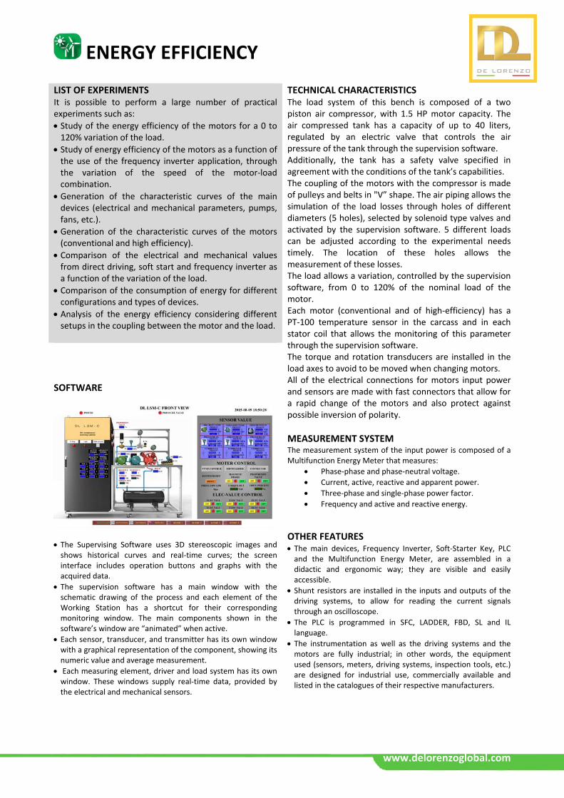
SOFTWARE
The Supervising Software uses 3D stereoscopic images and shows historical curves and real‐time curves; the screen interface includes operation buttons and graphs with the acquired data.
The supervision software has a main window with the schematic drawing of the process and each element of the Working Station has a shortcut for their corresponding monitoring window. The main components shown in the software’s window are “animated” when active.
Each sensor, transducer, and transmitter has its own window with a graphical representation of the component, showing its numeric value and average measurement.
Each measuring element, driver and load system has its own window. These windows supply real‐time data, provided by the electrical and mechanical sensors.
Oil & Gas / Chemistry
www.delorenzoglobal.com
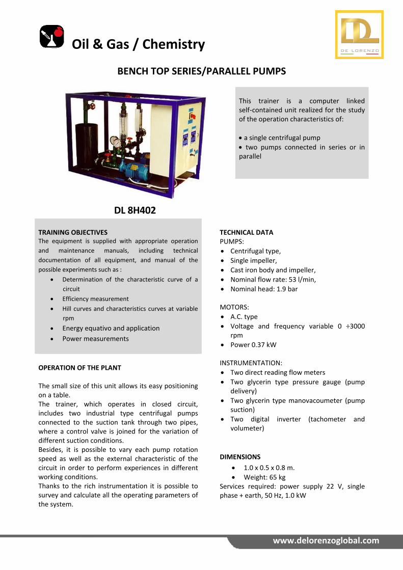
BENCH TOP SERIES/PARALLEL PUMPS
DL 8H402
This trainer is a computer linked self‐contained unit realized for the study of the operation characteristics of:
a single centrifugal pump
two pumps connected in series or in parallel
TRAINING OBJECTIVES The equipment is supplied with appropriate operation
and maintenance manuals, including technical
documentation of all equipment, and manual of the
possible experiments such as :
Determination of the characteristic curve of a
circuit
Efficiency measurement
Hill curves and characteristics curves at variable
rpm
Energy equativo and application
Power measurements
TECHNICAL DATA PUMPS:
Centrifugal type,
Single impeller,
Cast iron body and impeller,
Nominal flow rate: 53 l/min,
Nominal head: 1.9 bar MOTORS:
A.C. type
Voltage and frequency variable 0 ÷3000 rpm
Power 0.37 kW INSTRUMENTATION:
Two direct reading flow meters
Two glycerin type pressure gauge (pump delivery)
Two glycerin type manovacoumeter (pump suction)
Two digital inverter (tachometer and volumeter)
DIMENSIONS
1.0 x 0.5 x 0.8 m.
Weight: 65 kg Services required: power supply 22 V, single phase + earth, 50 Hz, 1.0 kW
OPERATION OF THE PLANT The small size of this unit allows its easy positioning on a table. The trainer, which operates in closed circuit, includes two industrial type centrifugal pumps connected to the suction tank through two pipes, where a control valve is joined for the variation of different suction conditions. Besides, it is possible to vary each pump rotation speed as well as the external characteristic of the circuit in order to perform experiences in different working conditions. Thanks to the rich instrumentation it is possible to survey and calculate all the operating parameters of the system.
Oil & Gas / Chemistry
www.delorenzoglobal.com
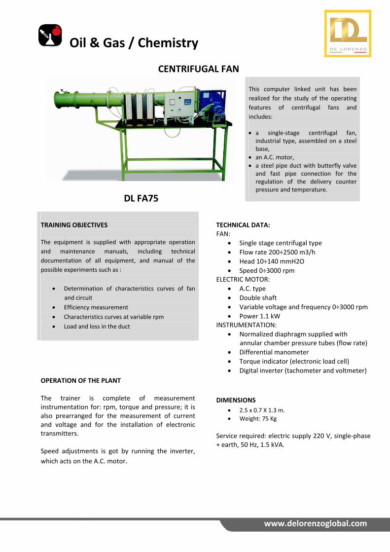
CENTRIFUGAL FAN
DL FA75
This computer linked unit has been
realized for the study of the operating
features of centrifugal fans and
includes:
a single‐stage centrifugal fan, industrial type, assembled on a steel base,
an A.C. motor,
a steel pipe duct with butterfly valve and fast pipe connection for the regulation of the delivery counter pressure and temperature.
TRAINING OBJECTIVES The equipment is supplied with appropriate operation
and maintenance manuals, including technical
documentation of all equipment, and manual of the
possible experiments such as :
Determination of characteristics curves of fan
and circuit
Efficiency measurement
Characteristics curves at variable rpm
Load and loss in the duct
TECHNICAL DATA: FAN:
Single stage centrifugal type
Flow rate 200÷2500 m3/h
Head 10÷140 mmH2O
Speed 0÷3000 rpm ELECTRIC MOTOR:
A.C. type
Double shaft
Variable voltage and frequency 0÷3000 rpm
Power 1.1 kW INSTRUMENTATION:
Normalized diaphragm supplied with annular chamber pressure tubes (flow rate)
Differential manometer
Torque indicator (electronic load cell)
Digital inverter (tachometer and voltmeter)
DIMENSIONS
2.5 x 0.7 X 1.3 m.
Weight: 75 Kg
Service required: electric supply 220 V, single‐phase + earth, 50 Hz, 1.5 kVA.
OPERATION OF THE PLANT The trainer is complete of measurement instrumentation for: rpm, torque and pressure; it is also prearranged for the measurement of current and voltage and for the installation of electronic transmitters. Speed adjustments is got by running the inverter,
which acts on the A.C. motor.
Oil & Gas / Chemistry
www.delorenzoglobal.com
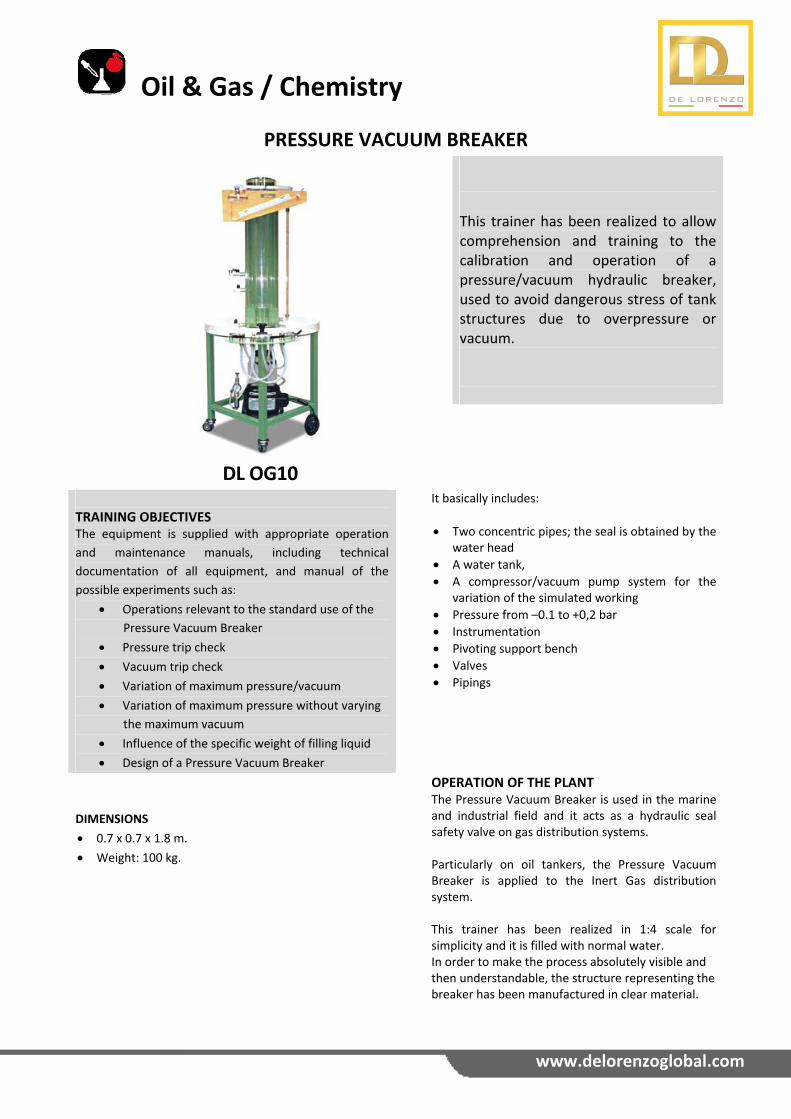
PRESSURE VACUUM BREAKER
DL OG10
This trainer has been realized to allow comprehension and training to the calibration and operation of a pressure/vacuum hydraulic breaker, used to avoid dangerous stress of tank structures due to overpressure or vacuum.
TRAINING OBJECTIVES The equipment is supplied with appropriate operation
and maintenance manuals, including technical
documentation of all equipment, and manual of the
possible experiments such as:
Operations relevant to the standard use of the
Pressure Vacuum Breaker
Pressure trip check
Vacuum trip check
Variation of maximum pressure/vacuum
Variation of maximum pressure without varying
the maximum vacuum
Influence of the specific weight of filling liquid
Design of a Pressure Vacuum Breaker
It basically includes:
Two concentric pipes; the seal is obtained by the water head
A water tank,
A compressor/vacuum pump system for the variation of the simulated working
Pressure from –0.1 to +0,2 bar
Instrumentation
Pivoting support bench
Valves
Pipings
DIMENSIONS
0.7 x 0.7 x 1.8 m.
Weight: 100 kg.
OPERATION OF THE PLANT The Pressure Vacuum Breaker is used in the marine and industrial field and it acts as a hydraulic seal safety valve on gas distribution systems. Particularly on oil tankers, the Pressure Vacuum Breaker is applied to the Inert Gas distribution system. This trainer has been realized in 1:4 scale for simplicity and it is filled with normal water. In order to make the process absolutely visible and then understandable, the structure representing the breaker has been manufactured in clear material.
Oil & Gas / Chemistry
www.delorenzoglobal.com
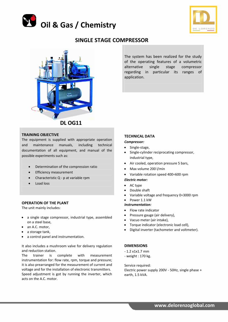
SINGLE STAGE COMPRESSOR
DL OG11
The system has been realized for the study of the operating features of a volumetric alternative single stage compressor regarding in particular its ranges of application.
TRAINING OBJECTIVE The equipment is supplied with appropriate operation
and maintenance manuals, including technical
documentation of all equipment, and manual of the
possible experiments such as:
Determination of the compression ratio
Efficiency measurement
Characteristic Q ‐ p at variable rpm
Load loss
TECHNICAL DATA Compressor:
Single‐stage,
Single‐cylinder reciprocating compressor,
industrial type,
Air cooled, operation pressure 5 bars,
Max volume 200 l/min
Variable rotation speed 400÷600 rpm
Electric motor:
AC type
Double shaft
Variable voltage and frequency 0÷3000 rpm
Power 1.1 kW Instrumentation:
Flow rate indicator
Pressure gauge (air delivery),
Vacuo meter (air intake),
Torque indicator (electronic load cell),
Digital inverter (tachometer and voltmeter).
DIMENSIONS
‐ 1.2 x1x1.7 mm ‐ weight : 170 kg. Service required: Electric power supply 200V ‐ 50Hz, single phase + earth, 1.5 kVA.
OPERATION OF THE PLANT The unit mainly includes:
a single stage compressor, industrial type, assembled on a steel base,
an A.C. motor,
a storage tank,
a control panel and instrumentation. It also includes a mushroom valve for delivery regulation and reduction station. The trainer is complete with measurement instrumentation for: flow rate, rpm, torque and pressure; it is also prearranged for the measurement of current and voltage and for the installation of electronic transmitters. Speed adjustment is got by running the inverter, which acts on the A.C. motor.
Oil & Gas / Chemistry
www.delorenzoglobal.com
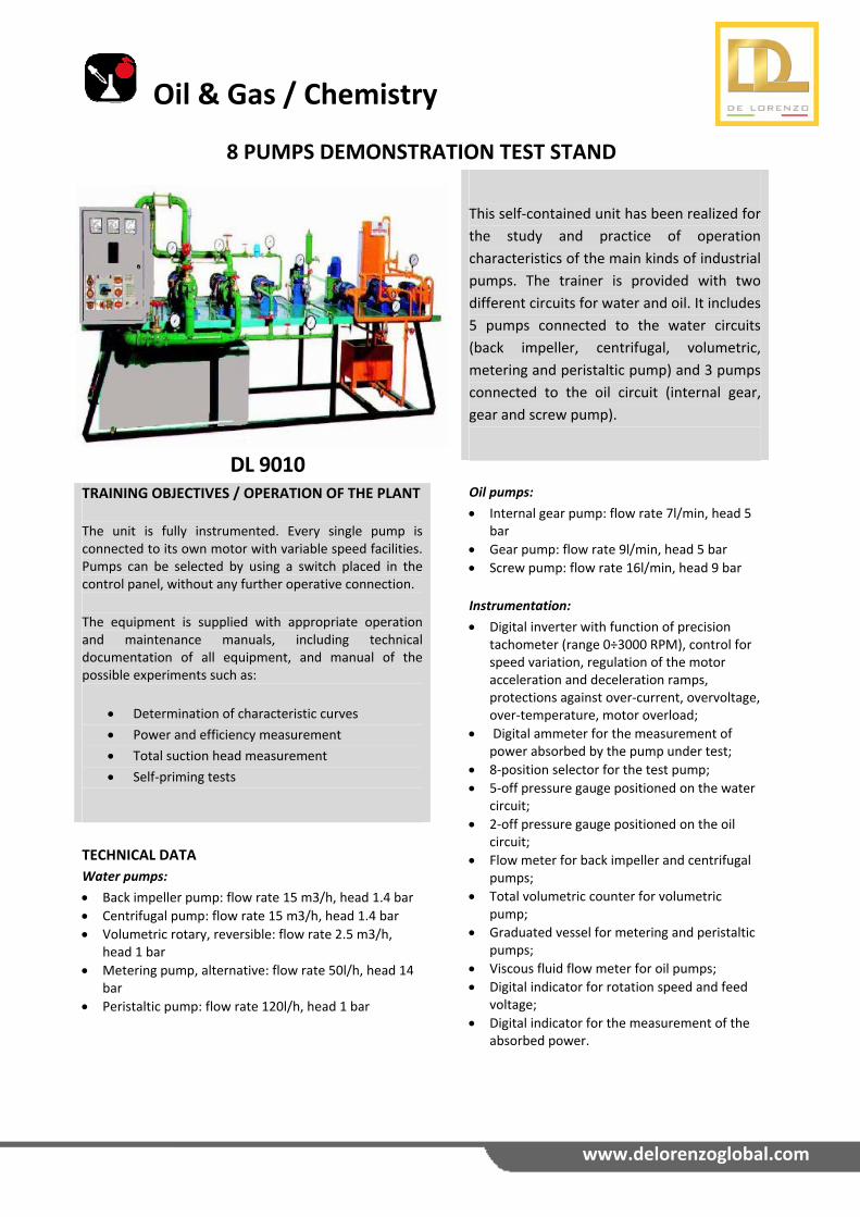
8 PUMPS DEMONSTRATION TEST STAND
DL 9010
This self‐contained unit has been realized for
the study and practice of operation
characteristics of the main kinds of industrial
pumps. The trainer is provided with two
different circuits for water and oil. It includes
5 pumps connected to the water circuits
(back impeller, centrifugal, volumetric,
metering and peristaltic pump) and 3 pumps
connected to the oil circuit (internal gear,
gear and screw pump).
TRAINING OBJECTIVES / OPERATION OF THE PLANT The unit is fully instrumented. Every single pump is connected to its own motor with variable speed facilities. Pumps can be selected by using a switch placed in the control panel, without any further operative connection.
The equipment is supplied with appropriate operation and maintenance manuals, including technical documentation of all equipment, and manual of the possible experiments such as:
Determination of characteristic curves
Power and efficiency measurement
Total suction head measurement
Self‐priming tests
Oil pumps:
Internal gear pump: flow rate 7l/min, head 5 bar
Gear pump: flow rate 9l/min, head 5 bar
Screw pump: flow rate 16l/min, head 9 bar
Instrumentation:
Digital inverter with function of precision tachometer (range 0÷3000 RPM), control for speed variation, regulation of the motor acceleration and deceleration ramps, protections against over‐current, overvoltage, over‐temperature, motor overload;
Digital ammeter for the measurement of power absorbed by the pump under test;
8‐position selector for the test pump;
5‐off pressure gauge positioned on the water circuit;
2‐off pressure gauge positioned on the oil circuit;
Flow meter for back impeller and centrifugal pumps;
Total volumetric counter for volumetric pump;
Graduated vessel for metering and peristaltic pumps;
Viscous fluid flow meter for oil pumps;
Digital indicator for rotation speed and feed voltage;
Digital indicator for the measurement of the absorbed power.
TECHNICAL DATA Water pumps:
Back impeller pump: flow rate 15 m3/h, head 1.4 bar
Centrifugal pump: flow rate 15 m3/h, head 1.4 bar
Volumetric rotary, reversible: flow rate 2.5 m3/h, head 1 bar
Metering pump, alternative: flow rate 50l/h, head 14 bar
Peristaltic pump: flow rate 120l/h, head 1 bar
RENEWABLE ENERGIES
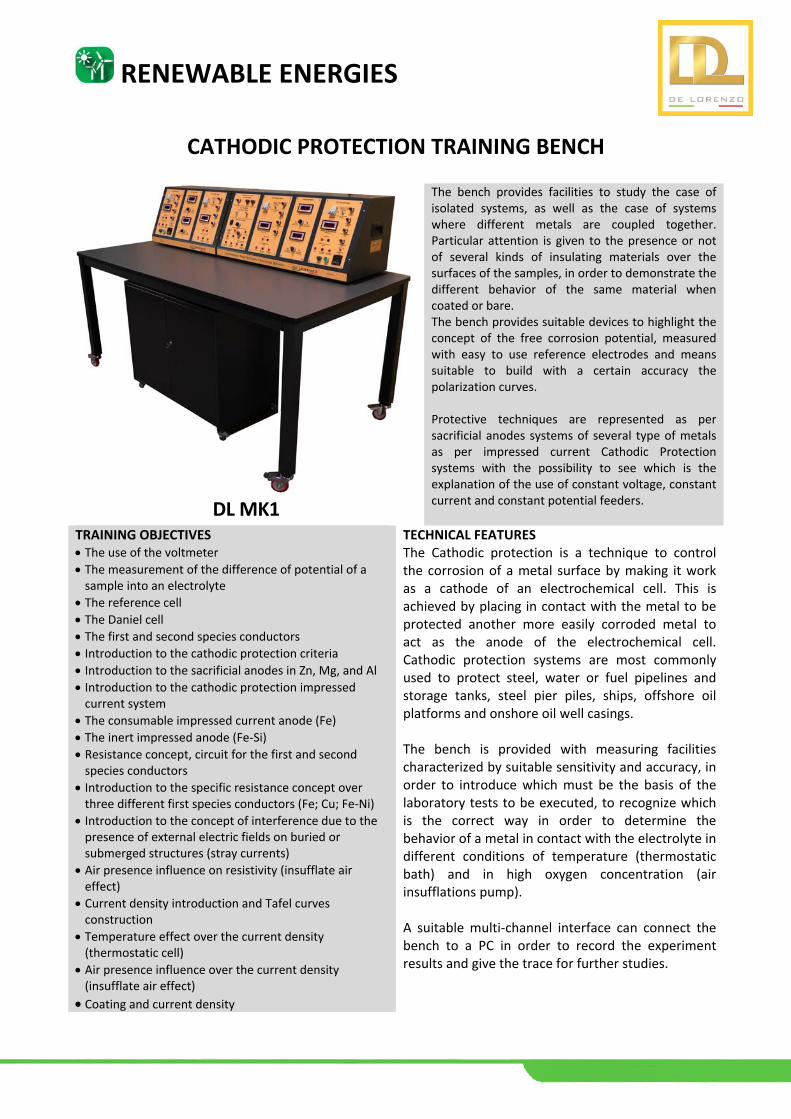
CATHODIC PROTECTION TRAINING BENCH
DL MK1
The bench provides facilities to study the case of isolated systems, as well as the case of systems where different metals are coupled together. Particular attention is given to the presence or not of several kinds of insulating materials over the surfaces of the samples, in order to demonstrate the different behavior of the same material when coated or bare. The bench provides suitable devices to highlight the concept of the free corrosion potential, measured with easy to use reference electrodes and means suitable to build with a certain accuracy the polarization curves. Protective techniques are represented as per sacrificial anodes systems of several type of metals as per impressed current Cathodic Protection systems with the possibility to see which is the explanation of the use of constant voltage, constant current and constant potential feeders.
TRAINING OBJECTIVES The use of the voltmeter
The measurement of the difference of potential of a sample into an electrolyte
The reference cell The Daniel cell The first and second species conductors Introduction to the cathodic protection criteria Introduction to the sacrificial anodes in Zn, Mg, and Al
Introduction to the cathodic protection impressed current system
The consumable impressed current anode (Fe)
The inert impressed anode (Fe‐Si)
Resistance concept, circuit for the first and second species conductors
Introduction to the specific resistance concept over three different first species conductors (Fe; Cu; Fe‐Ni)
Introduction to the concept of interference due to the presence of external electric fields on buried or submerged structures (stray currents)
Air presence influence on resistivity (insufflate air effect)
Current density introduction and Tafel curves construction
Temperature effect over the current density (thermostatic cell)
Air presence influence over the current density (insufflate air effect)
Coating and current density
TECHNICAL FEATURES The Cathodic protection is a technique to control the corrosion of a metal surface by making it work as a cathode of an electrochemical cell. This is achieved by placing in contact with the metal to be protected another more easily corroded metal to act as the anode of the electrochemical cell. Cathodic protection systems are most commonly used to protect steel, water or fuel pipelines and storage tanks, steel pier piles, ships, offshore oil platforms and onshore oil well casings. The bench is provided with measuring facilities characterized by suitable sensitivity and accuracy, in order to introduce which must be the basis of the laboratory tests to be executed, to recognize which is the correct way in order to determine the behavior of a metal in contact with the electrolyte in different conditions of temperature (thermostatic bath) and in high oxygen concentration (air insufflations pump). A suitable multi‐channel interface can connect the bench to a PC in order to record the experiment results and give the trace for further studies.
RENEWABLE ENERGIES
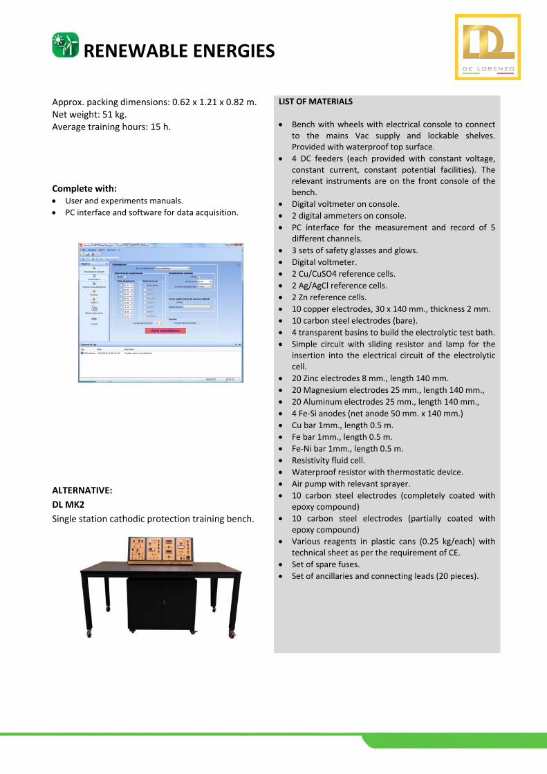
Approx. packing dimensions: 0.62 x 1.21 x 0.82 m. Net weight: 51 kg. Average training hours: 15 h. Complete with: User and experiments manuals.
PC interface and software for data acquisition.
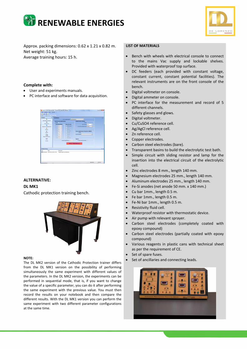
ALTERNATIVE:
DL MK2
Single station cathodic protection training bench.
LIST OF MATERIALS
Bench with wheels with electrical console to connect to the mains Vac supply and lockable shelves. Provided with waterproof top surface.
4 DC feeders (each provided with constant voltage, constant current, constant potential facilities). The relevant instruments are on the front console of the bench.
Digital voltmeter on console.
2 digital ammeters on console.
PC interface for the measurement and record of 5 different channels.
3 sets of safety glasses and glows.
Digital voltmeter.
2 Cu/CuSO4 reference cells.
2 Ag/AgCl reference cells.
2 Zn reference cells.
10 copper electrodes, 30 x 140 mm., thickness 2 mm.
10 carbon steel electrodes (bare).
4 transparent basins to build the electrolytic test bath.
Simple circuit with sliding resistor and lamp for the insertion into the electrical circuit of the electrolytic cell.
20 Zinc electrodes 8 mm., length 140 mm.
20 Magnesium electrodes 25 mm., length 140 mm.,
20 Aluminum electrodes 25 mm., length 140 mm.,
4 Fe‐Si anodes (net anode 50 mm. x 140 mm.)
Cu bar 1mm., length 0.5 m.
Fe bar 1mm., length 0.5 m.
Fe‐Ni bar 1mm., length 0.5 m.
Resistivity fluid cell.
Waterproof resistor with thermostatic device.
Air pump with relevant sprayer.
10 carbon steel electrodes (completely coated with epoxy compound)
10 carbon steel electrodes (partially coated with epoxy compound)
Various reagents in plastic cans (0.25 kg/each) with technical sheet as per the requirement of CE.
Set of spare fuses.
Set of ancillaries and connecting leads (20 pieces).
RENEWABLE ENERGIES
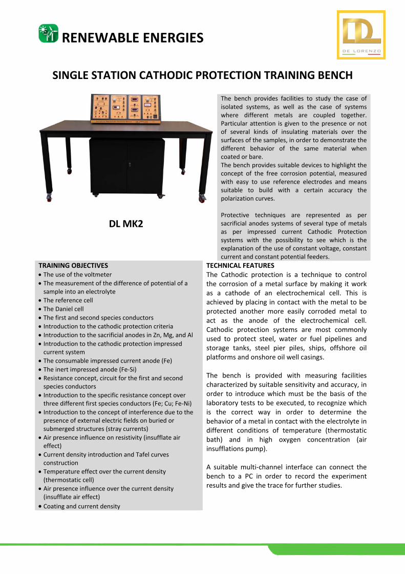
SINGLE STATION CATHODIC PROTECTION TRAINING BENCH
DL MK2
The bench provides facilities to study the case of isolated systems, as well as the case of systems where different metals are coupled together. Particular attention is given to the presence or not of several kinds of insulating materials over the surfaces of the samples, in order to demonstrate the different behavior of the same material when coated or bare. The bench provides suitable devices to highlight the concept of the free corrosion potential, measured with easy to use reference electrodes and means suitable to build with a certain accuracy the polarization curves. Protective techniques are represented as per sacrificial anodes systems of several type of metals as per impressed current Cathodic Protection systems with the possibility to see which is the explanation of the use of constant voltage, constant current and constant potential feeders.
TRAINING OBJECTIVES The use of the voltmeter
The measurement of the difference of potential of a sample into an electrolyte
The reference cell The Daniel cell The first and second species conductors Introduction to the cathodic protection criteria Introduction to the sacrificial anodes in Zn, Mg, and Al
Introduction to the cathodic protection impressed current system
The consumable impressed current anode (Fe)
The inert impressed anode (Fe‐Si)
Resistance concept, circuit for the first and second species conductors
Introduction to the specific resistance concept over three different first species conductors (Fe; Cu; Fe‐Ni)
Introduction to the concept of interference due to the presence of external electric fields on buried or submerged structures (stray currents)
Air presence influence on resistivity (insufflate air effect)
Current density introduction and Tafel curves construction
Temperature effect over the current density (thermostatic cell)
Air presence influence over the current density (insufflate air effect)
Coating and current density
TECHNICAL FEATURES The Cathodic protection is a technique to control the corrosion of a metal surface by making it work as a cathode of an electrochemical cell. This is achieved by placing in contact with the metal to be protected another more easily corroded metal to act as the anode of the electrochemical cell. Cathodic protection systems are most commonly used to protect steel, water or fuel pipelines and storage tanks, steel pier piles, ships, offshore oil platforms and onshore oil well casings. The bench is provided with measuring facilities characterized by suitable sensitivity and accuracy, in order to introduce which must be the basis of the laboratory tests to be executed, to recognize which is the correct way in order to determine the behavior of a metal in contact with the electrolyte in different conditions of temperature (thermostatic bath) and in high oxygen concentration (air insufflations pump). A suitable multi‐channel interface can connect the bench to a PC in order to record the experiment results and give the trace for further studies.
RENEWABLE ENERGIES
Approx. packing dimensions: 0.62 x 1.21 x 0.82 m. Net weight: 51 kg. Average training hours: 15 h. Complete with: User and experiments manuals.
PC interface and software for data acquisition.
ALTERNATIVE:
DL MK1
Cathodic protection training bench.
NOTE: The DL MK2 version of the Cathodic Protection trainer differs from the DL MK1 version on the possibility of performing simultaneously the same experiment with different values of the parameters. In the DL MK2 version, the experiments can be performed in sequential mode, that is, if you want to change the value of a specific parameter, you can do it after performing the same experiment with the previous value. You must then record the results on your notebook and then compare the different results. With the DL MK1 version you can perform the same experiment with two different parameter configurations at the same time.
LIST OF MATERIALS
Bench with wheels with electrical console to connect to the mains Vac supply and lockable shelves. Provided with waterproof top surface.
DC feeders (each provided with constant voltage, constant current, constant potential facilities). The relevant instruments are on the front console of the bench.
Digital voltmeter on console.
Digital ammeter on console.
PC interface for the measurement and record of 5 different channels.
Safety glasses and glows.
Digital voltmeter.
Cu/CuSO4 reference cell.
Ag/AgCl reference cell.
Zn reference cell.
Copper electrodes.
Carbon steel electrodes (bare).
Transparent basins to build the electrolytic test bath.
Simple circuit with sliding resistor and lamp for the insertion into the electrical circuit of the electrolytic cell.
Zinc electrodes 8 mm., length 140 mm.
Magnesium electrodes 25 mm., length 140 mm.
Aluminum electrodes 25 mm., length 140 mm.
Fe‐Si anodes (net anode 50 mm. x 140 mm.)
Cu bar 1mm., length 0.5 m.
Fe bar 1mm., length 0.5 m.
Fe‐Ni bar 1mm., length 0.5 m.
Resistivity fluid cell.
Waterproof resistor with thermostatic device.
Air pump with relevant sprayer.
Carbon steel electrodes (completely coated with epoxy compound)
Carbon steel electrodes (partially coated with epoxy compound)
Various reagents in plastic cans with technical sheet as per the requirement of CE.
Set of spare fuses.
Set of ancillaries and connecting leads.