Embed Size (px)
Citation preview
8/3/2019 Ddj2003 Notes Chap1 (Dc Circuits)
http://slidepdf.com/reader/full/ddj2003-notes-chap1-dc-circuits 1/69
1
CHAPTER 1
DIRECT CURRENT (DC)
CIRCUITS
8/3/2019 Ddj2003 Notes Chap1 (Dc Circuits)
http://slidepdf.com/reader/full/ddj2003-notes-chap1-dc-circuits 2/69
2
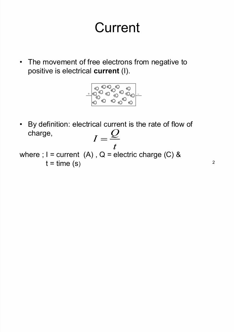
Current
The movement of free electrons from negative to
positive is electrical current (I).
By definition: electrical current is the rate of flow of charge,
where ; I = current (A) , Q = electric charge (C) &
t = time (s)
t
Q I !
8/3/2019 Ddj2003 Notes Chap1 (Dc Circuits)
http://slidepdf.com/reader/full/ddj2003-notes-chap1-dc-circuits 3/69
3
There must be a driving influence to cause the
continuous current flow. This influence is provided by the
source which causes the current to leave at a high
potential and to move round the circuit until it returns to
the source at a low potential. The term voltage meant a
difference of potential and is expressed in volts. One volt is the potential difference between two points when one
joule of energy is used to move one coulomb from one
point to the other.
where ; V = voltage (V) , W = energy (J) & Q =
charge (C)
Q
W V !
Voltage

8/3/2019 Ddj2003 Notes Chap1 (Dc Circuits)
http://slidepdf.com/reader/full/ddj2003-notes-chap1-dc-circuits 4/69
4
Energy is the ability to do work; and
Power is the rate at which energy is used.
Power = energy/time;
Therefore: W = Pt (J)where ; W = energy (J) , P = power (W) & t = time (s)
and,
WattsVIt
VQ
t
W P !!!
Energy and Power
8/3/2019 Ddj2003 Notes Chap1 (Dc Circuits)
http://slidepdf.com/reader/full/ddj2003-notes-chap1-dc-circuits 5/69
5
The driving influence that causes a current to flow is termed the
electromotive force, hereafter called the e.m.f and is alwaysconnected with energy conversion
An electromotive force, e.m.f. is that which tends to produce an
electric current in a circuit. The unit of e.m.f. is volt (V), symbolized
by e. The principal sources of e.m.f. are as follows:
1. The electrodes of dissimilar materials immersed in an
electrolyte, as in primary and secondary cells, i.e. batteries.
(Sources from batteries is in dc current or constant current)
2. The relative movement of a conductor and a magnetic flux, in
an electric generator. This source can be expressed as thevariation of magnetic flux linked with a coil. (Basic principle of
generators)
3. The difference of temperature between junctions of dissimilar
metals, as in thermo-junction.
EMF

8/3/2019 Ddj2003 Notes Chap1 (Dc Circuits)
http://slidepdf.com/reader/full/ddj2003-notes-chap1-dc-circuits 6/69
6
Resistance
The resistance of any material is due
primarily to four factors:
± Material resistivity ( V) ± Length (l)
± Cross-sectional area (A)
± Temperature of the material
8/3/2019 Ddj2003 Notes Chap1 (Dc Circuits)
http://slidepdf.com/reader/full/ddj2003-notes-chap1-dc-circuits 7/69
7
Temperature Effects
Temperature Coefficient of Resistance
± the higher the temperature coefficient of
resistance for a material, the more sensitive
the resistance level to changes in temperature
8/3/2019 Ddj2003 Notes Chap1 (Dc Circuits)
http://slidepdf.com/reader/full/ddj2003-notes-chap1-dc-circuits 8/69
8
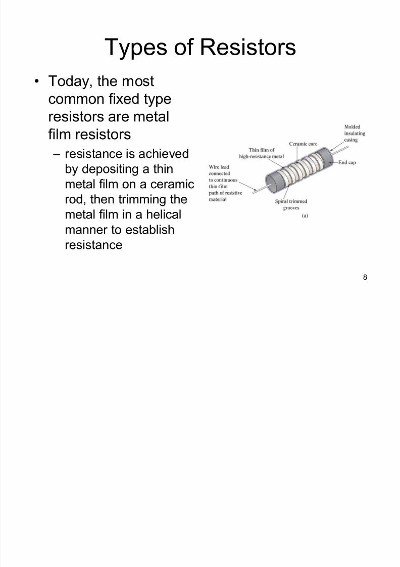
Types of Resistors
Today, the most
common fixed type
resistors are metal
film resistors ± resistance is achieved
by depositing a thin
metal film on a ceramic
rod, then trimming the
metal film in a helicalmanner to establish
resistance
8/3/2019 Ddj2003 Notes Chap1 (Dc Circuits)
http://slidepdf.com/reader/full/ddj2003-notes-chap1-dc-circuits 9/69
9
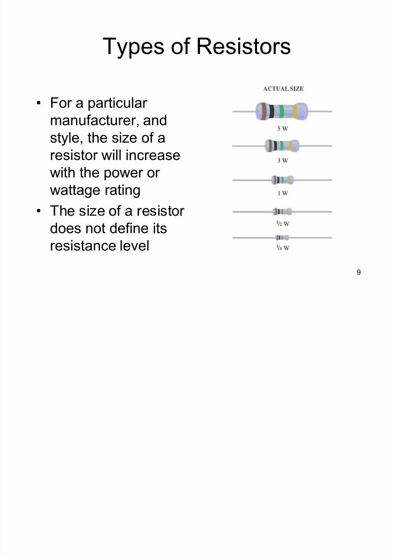
Types of Resistors
For a particular
manufacturer, and
style, the size of aresistor will increase
with the power or
wattage rating
The size of a resistor does not define its
resistance level
8/3/2019 Ddj2003 Notes Chap1 (Dc Circuits)
http://slidepdf.com/reader/full/ddj2003-notes-chap1-dc-circuits 10/69
10
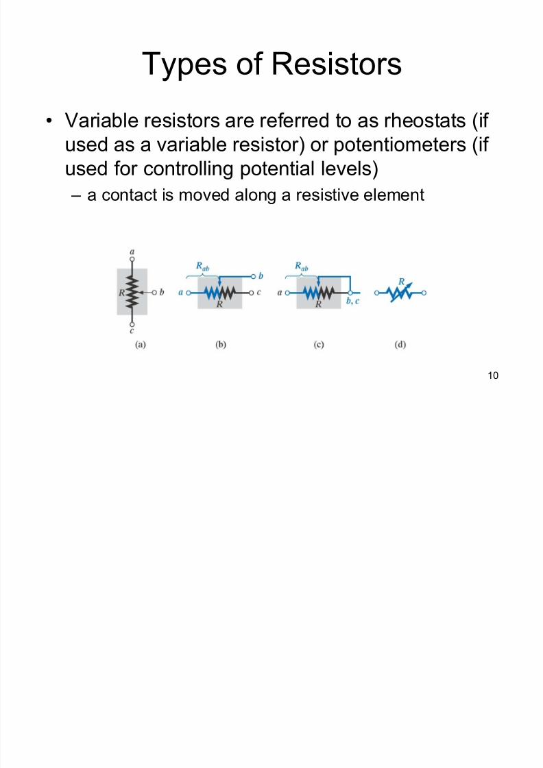
Types of Resistors
Variable resistors are referred to as rheostats (if
used as a variable resistor) or potentiometers (if
used for controlling potential levels)
± a contact is moved along a resistive element
8/3/2019 Ddj2003 Notes Chap1 (Dc Circuits)
http://slidepdf.com/reader/full/ddj2003-notes-chap1-dc-circuits 11/69
11
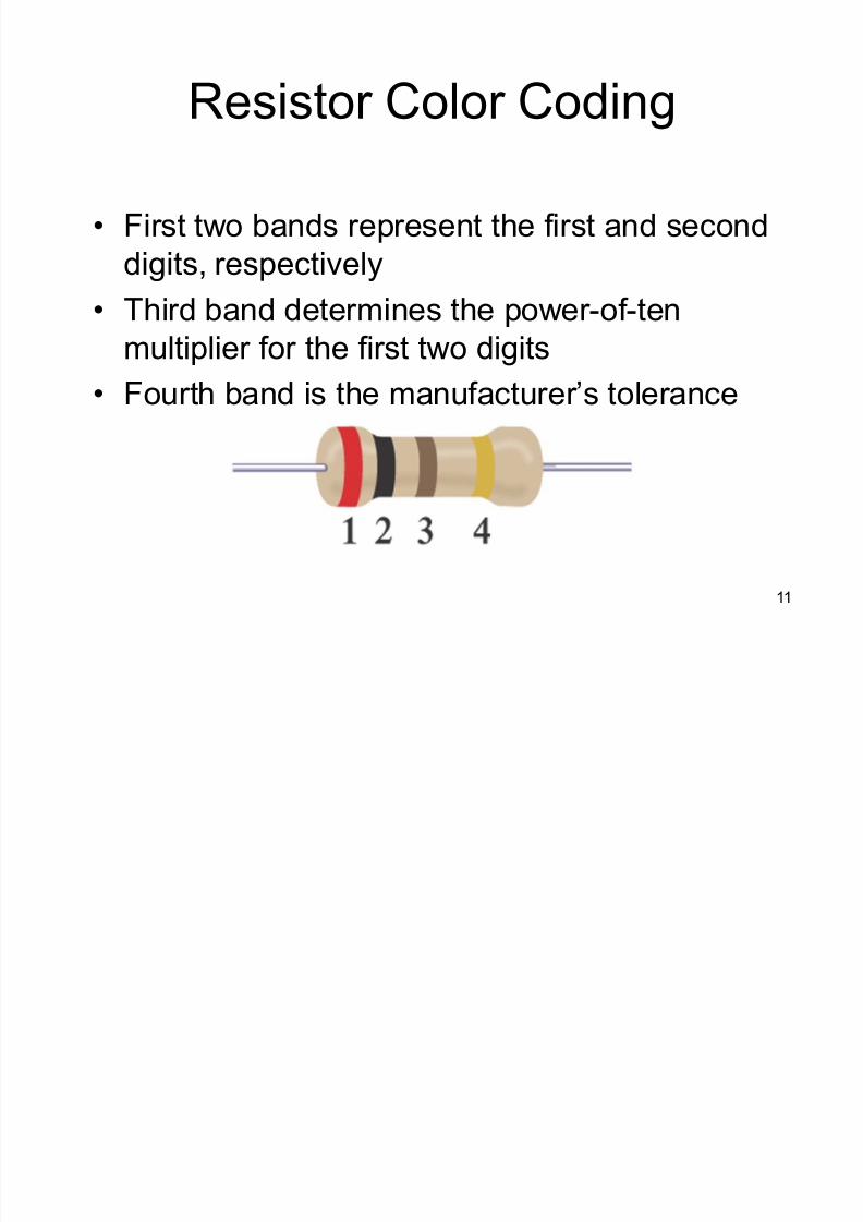
Resistor Color Coding
First two bands represent the first and second
digits, respectively
Third band determines the power-of-tenmultiplier for the first two digits
Fourth band is the manufacturer¶s tolerance
8/3/2019 Ddj2003 Notes Chap1 (Dc Circuits)
http://slidepdf.com/reader/full/ddj2003-notes-chap1-dc-circuits 12/69
12
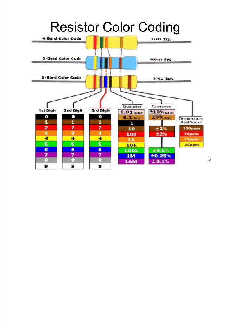
Resistor Color Coding
8/3/2019 Ddj2003 Notes Chap1 (Dc Circuits)
http://slidepdf.com/reader/full/ddj2003-notes-chap1-dc-circuits 13/69
13
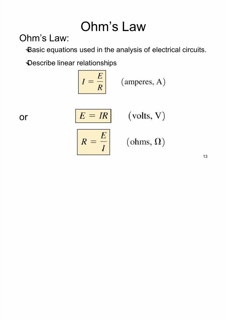
Ohm¶s Law
Ohm¶s Law: Basic equations used in the analysis of electrical circuits.
Describe linear relationships
or
8/3/2019 Ddj2003 Notes Chap1 (Dc Circuits)
http://slidepdf.com/reader/full/ddj2003-notes-chap1-dc-circuits 14/69
14
Ohm¶s Law
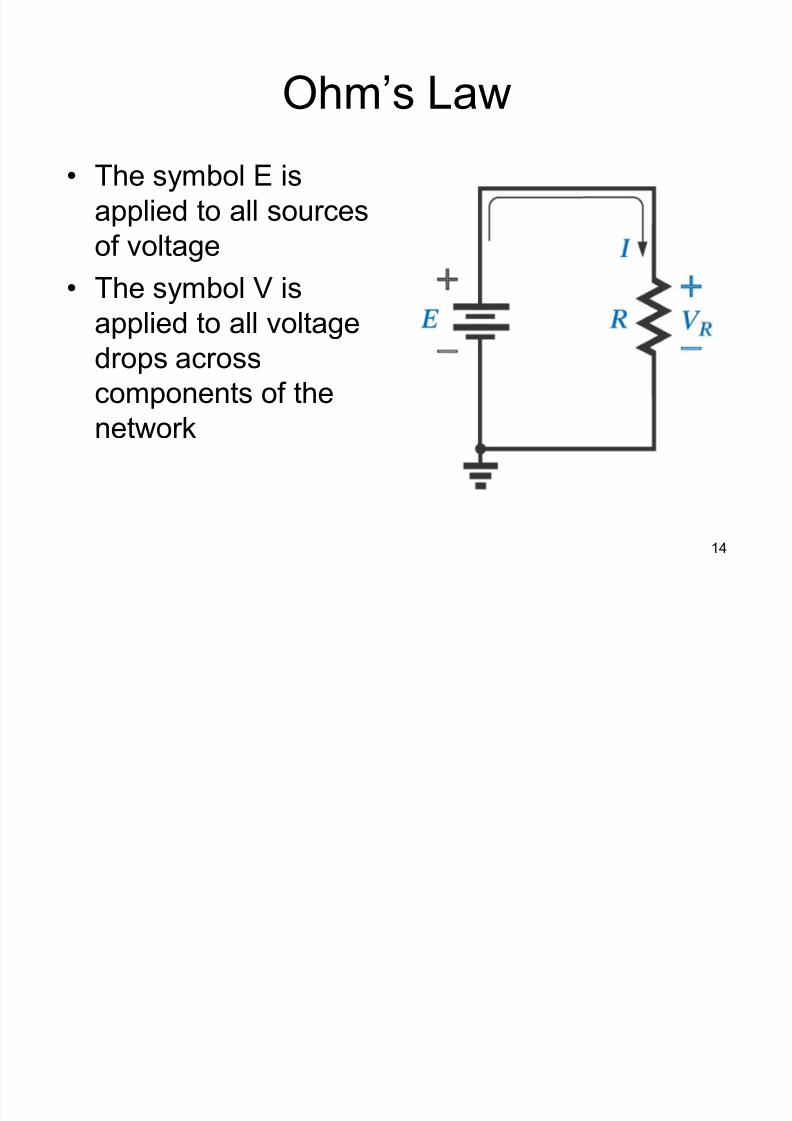
The symbol E is
applied to all sources
of voltage
The symbol V isapplied to all voltage
drops across
components of the
network
8/3/2019 Ddj2003 Notes Chap1 (Dc Circuits)
http://slidepdf.com/reader/full/ddj2003-notes-chap1-dc-circuits 15/69
15
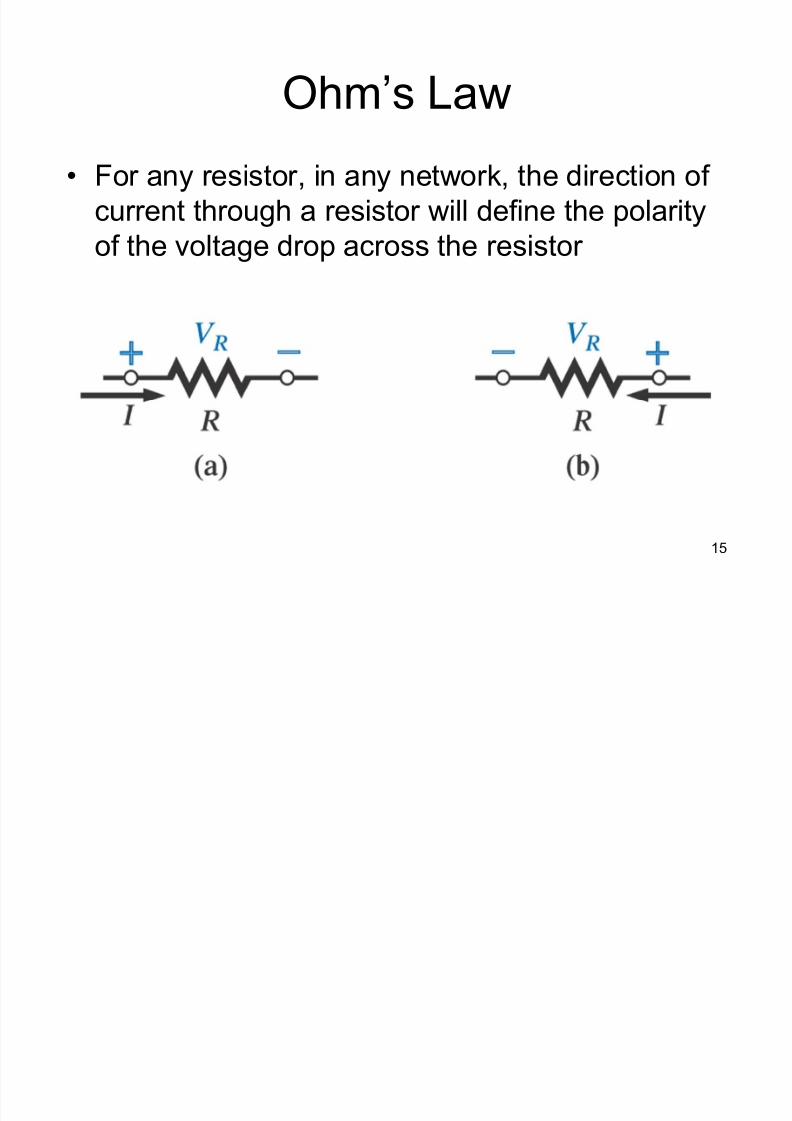
Ohm¶s Law
For any resistor, in any network, the direction of
current through a resistor will define the polarity
of the voltage drop across the resistor
8/3/2019 Ddj2003 Notes Chap1 (Dc Circuits)
http://slidepdf.com/reader/full/ddj2003-notes-chap1-dc-circuits 16/69
16
SERIES CIRCUITS

8/3/2019 Ddj2003 Notes Chap1 (Dc Circuits)
http://slidepdf.com/reader/full/ddj2003-notes-chap1-dc-circuits 17/69
17
Resistors in Series
A series circuit provides only one path for current between two points so that the current isthe same through each series resistor.
8/3/2019 Ddj2003 Notes Chap1 (Dc Circuits)
http://slidepdf.com/reader/full/ddj2003-notes-chap1-dc-circuits 18/69
18
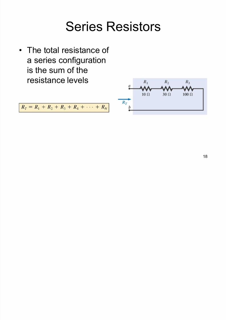
Series Resistors
The total resistance of
a series configuration
is the sum of the
resistance levels

8/3/2019 Ddj2003 Notes Chap1 (Dc Circuits)
http://slidepdf.com/reader/full/ddj2003-notes-chap1-dc-circuits 19/69
19
Current in a Series Circuit
The current is the same through all points
in a series circuit. The current through
each resistor in a series circuit is the same
as the current through all the other
resistors that are in series with it.
8/3/2019 Ddj2003 Notes Chap1 (Dc Circuits)
http://slidepdf.com/reader/full/ddj2003-notes-chap1-dc-circuits 20/69
20
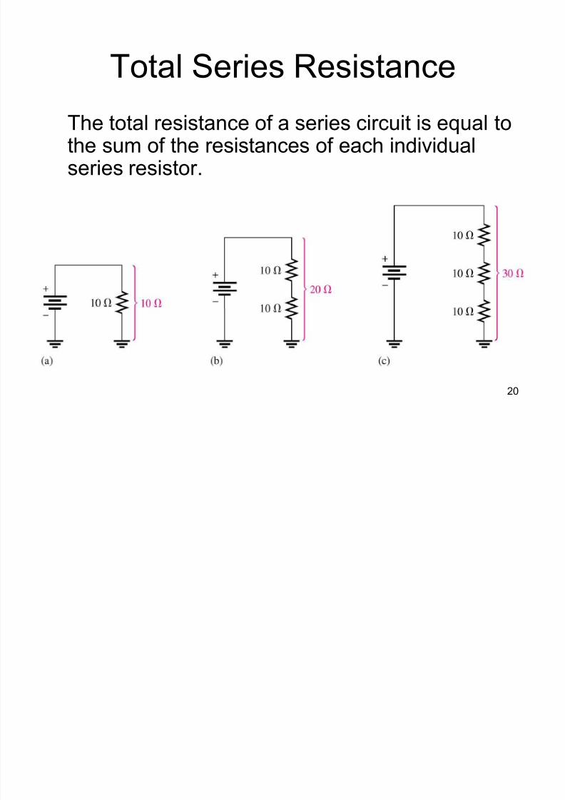
Total Series Resistance
The total resistance of a series circuit is equal tothe sum of the resistances of each individualseries resistor.
8/3/2019 Ddj2003 Notes Chap1 (Dc Circuits)
http://slidepdf.com/reader/full/ddj2003-notes-chap1-dc-circuits 21/69
21
Series Resistance Formula
For any number of individual resistors
connected in series, the total resistance is
the sum of each of the individual values.
RT = R1 + R2 + R3 + . . . + Rn

8/3/2019 Ddj2003 Notes Chap1 (Dc Circuits)
http://slidepdf.com/reader/full/ddj2003-notes-chap1-dc-circuits 22/69
22
Ohm¶s Law in Series Circuits
Current through one of the series resistor is the
same as the current through each of the other
resistors and is the total current.
If you know the total voltage and the totalresistance, you can determine the total current
by using: IT = VT /RT
If you know the voltage drop across one of the
series resistors, you can determine the current
by using: I = VR /R

8/3/2019 Ddj2003 Notes Chap1 (Dc Circuits)
http://slidepdf.com/reader/full/ddj2003-notes-chap1-dc-circuits 23/69
23
Ohm¶s Law in Series Circuits
If you know the total current, you can find
the voltage drop across any of the series
resistors by using: VR
= ITR
The polarity of a voltage drop across a
resistor is positive at the end of the
resistor that is closest to the positive
terminal of the voltage source.

8/3/2019 Ddj2003 Notes Chap1 (Dc Circuits)
http://slidepdf.com/reader/full/ddj2003-notes-chap1-dc-circuits 24/69
24
Ohm¶s Law in Series Circuits
An open in a series circuit prevents
current; and, there is zero voltage drop
across each series resistor. The total
voltage appears across the points
between which there is an open.
8/3/2019 Ddj2003 Notes Chap1 (Dc Circuits)
http://slidepdf.com/reader/full/ddj2003-notes-chap1-dc-circuits 25/69
25
Power in a Series Circuit
The total amount of power in a series
resistive circuit is equal to the sum of the
powers in each resistor in series.
PT = P1 + P2 + P3 + . . . + Pn
8/3/2019 Ddj2003 Notes Chap1 (Dc Circuits)
http://slidepdf.com/reader/full/ddj2003-notes-chap1-dc-circuits 26/69
26
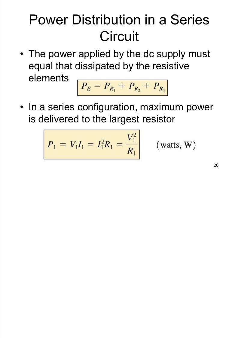
Power Distribution in a Series
Circuit The power applied by the dc supply must
equal that dissipated by the resistive
elements
In a series configuration, maximum power
is delivered to the largest resistor
8/3/2019 Ddj2003 Notes Chap1 (Dc Circuits)
http://slidepdf.com/reader/full/ddj2003-notes-chap1-dc-circuits 27/69
27
Power in a Resistor
The amount of power in a resistor is
important because the power rating of the
resistor must be high enough to handle the
expected power in the circuit.
8/3/2019 Ddj2003 Notes Chap1 (Dc Circuits)
http://slidepdf.com/reader/full/ddj2003-notes-chap1-dc-circuits 28/69
28
Voltage Sources in Series
A voltage source is an energy source that
provides a constant voltage to a load.
Batteries and electronic power supplied
are practical examples of dc voltage
sources.
8/3/2019 Ddj2003 Notes Chap1 (Dc Circuits)
http://slidepdf.com/reader/full/ddj2003-notes-chap1-dc-circuits 29/69
29
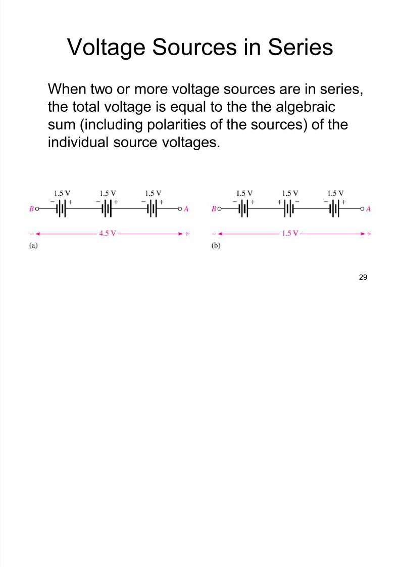
Voltage Sources in Series
When two or more voltage sources are in series,
the total voltage is equal to the the algebraic
sum (including polarities of the sources) of the
individual source voltages.
8/3/2019 Ddj2003 Notes Chap1 (Dc Circuits)
http://slidepdf.com/reader/full/ddj2003-notes-chap1-dc-circuits 30/69
30
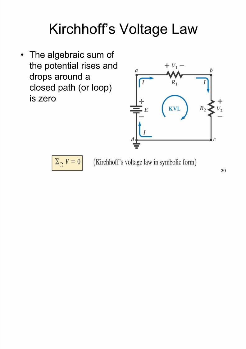
Kirchhoff¶s Voltage Law
The algebraic sum of
the potential rises and
drops around a
closed path (or loop)is zero
8/3/2019 Ddj2003 Notes Chap1 (Dc Circuits)
http://slidepdf.com/reader/full/ddj2003-notes-chap1-dc-circuits 31/69
31
Kirchhoff¶s Voltage Law
This law requires that we define a
closed path of investigation permitting
us to start at one point in the network,travel through the network, and find our
way back to the original starting point
8/3/2019 Ddj2003 Notes Chap1 (Dc Circuits)
http://slidepdf.com/reader/full/ddj2003-notes-chap1-dc-circuits 32/69
32
Kirchhoff¶s Voltage Law
The applied voltage of a series dc circuit
will equal the sum of the voltage drops of
the circuit
The sum of the voltage rises around a
closed path will always equal the sum of
the voltage drops
8/3/2019 Ddj2003 Notes Chap1 (Dc Circuits)
http://slidepdf.com/reader/full/ddj2003-notes-chap1-dc-circuits 33/69
33
Kirchhoff¶s Voltage Law
When applying Kirchhoff¶s voltage law, be sure
to concentrate on the polarities of the voltage
rises or drops rather than the type of elements
± do not treat a voltage drop across a resistive elementdifferently from a voltage rise (or drop) across a
source
± polarity indicates that a drop (or rise) has occurred,
not whether it is a resistive element or source
8/3/2019 Ddj2003 Notes Chap1 (Dc Circuits)
http://slidepdf.com/reader/full/ddj2003-notes-chap1-dc-circuits 34/69
34
Kirchhoff¶s Voltage Law
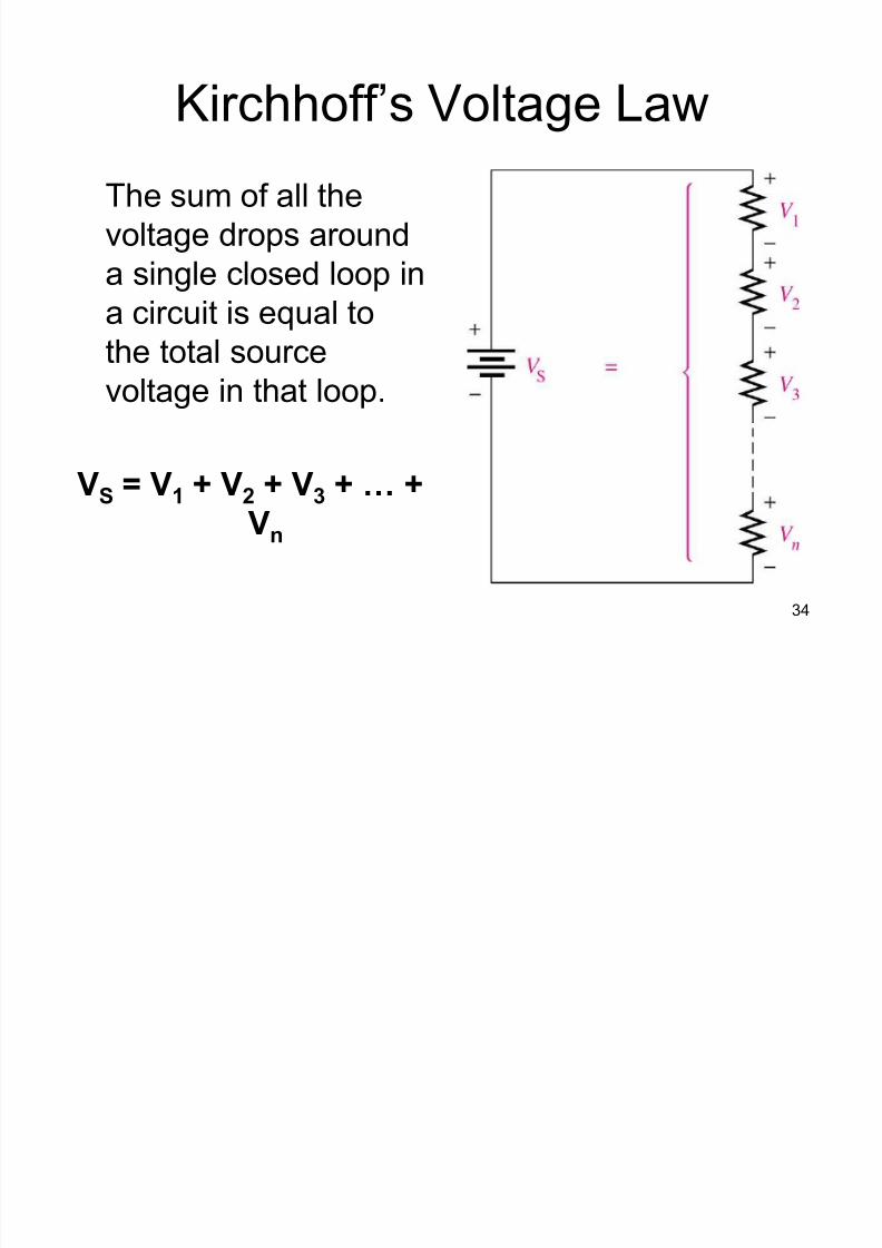
The sum of all the
voltage drops around
a single closed loop in
a circuit is equal tothe total source
voltage in that loop.
VS = V1 + V2 + V3 + « +
Vn
8/3/2019 Ddj2003 Notes Chap1 (Dc Circuits)
http://slidepdf.com/reader/full/ddj2003-notes-chap1-dc-circuits 35/69
35
Another Way to state
Kirchhoff¶s Voltage Law
The algebraic sum of all voltages (both
sources and drops) around a closed path
is zero.
VS
- V1
- V2
- V3
= 0
8/3/2019 Ddj2003 Notes Chap1 (Dc Circuits)
http://slidepdf.com/reader/full/ddj2003-notes-chap1-dc-circuits 36/69
36
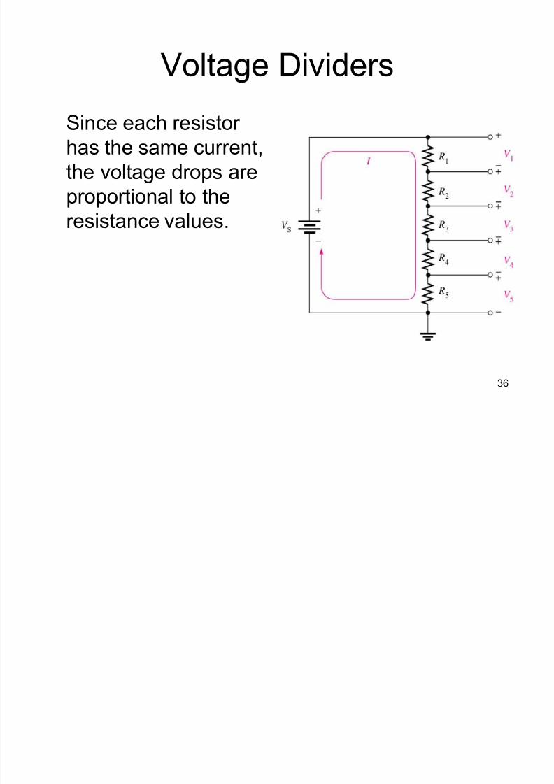
Voltage Dividers
Since each resistor
has the same current,
the voltage drops are
proportional to theresistance values.
8/3/2019 Ddj2003 Notes Chap1 (Dc Circuits)
http://slidepdf.com/reader/full/ddj2003-notes-chap1-dc-circuits 37/69
37
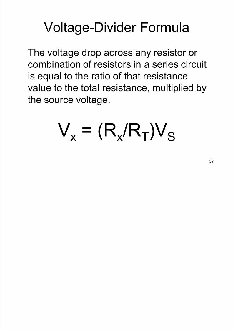
Voltage-Divider Formula
The voltage drop across any resistor or
combination of resistors in a series circuit
is equal to the ratio of that resistance
value to the total resistance, multiplied by
the source voltage.
Vx = (Rx/RT)VS
8/3/2019 Ddj2003 Notes Chap1 (Dc Circuits)
http://slidepdf.com/reader/full/ddj2003-notes-chap1-dc-circuits 38/69
38
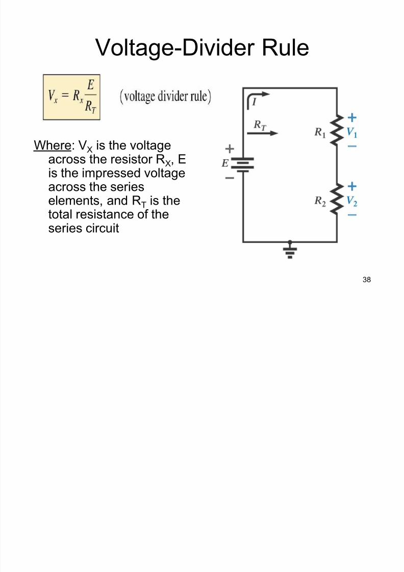
Voltage-Divider Rule
Where: VX is the voltageacross the resistor RX, Eis the impressed voltageacross the serieselements, and RT is the
total resistance of theseries circuit

8/3/2019 Ddj2003 Notes Chap1 (Dc Circuits)
http://slidepdf.com/reader/full/ddj2003-notes-chap1-dc-circuits 39/69
39
PARALLEL CIRCUITS

8/3/2019 Ddj2003 Notes Chap1 (Dc Circuits)
http://slidepdf.com/reader/full/ddj2003-notes-chap1-dc-circuits 40/69
40
Identifying Parallel Circuits
If there is more than one current path
(branch) between two separate points
(nodes), then there is a parallel circuit
between those two points.
8/3/2019 Ddj2003 Notes Chap1 (Dc Circuits)
http://slidepdf.com/reader/full/ddj2003-notes-chap1-dc-circuits 41/69
41
Voltage in Parallel Circuits
The voltage across any given branch of a
parallel circuit is equal to the voltage
across each of the other branches in
parallel.
8/3/2019 Ddj2003 Notes Chap1 (Dc Circuits)
http://slidepdf.com/reader/full/ddj2003-notes-chap1-dc-circuits 42/69
42
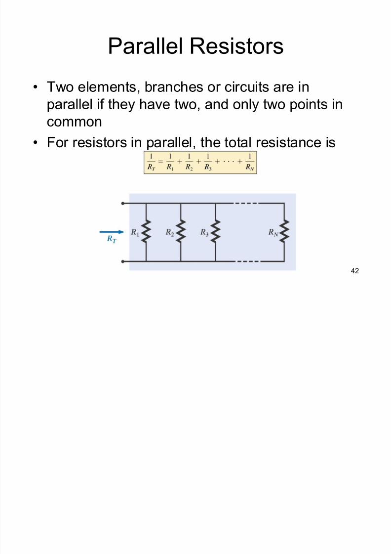
Parallel Resistors
Two elements, branches or circuits are in
parallel if they have two, and only two points in
common
For resistors in parallel, the total resistance is
8/3/2019 Ddj2003 Notes Chap1 (Dc Circuits)
http://slidepdf.com/reader/full/ddj2003-notes-chap1-dc-circuits 43/69
43
Parallel Resistors
The total resistance of parallel resistors
is less than the smallest parallel resistor
± If the smallest resistor of a parallel
combination is much smaller than the other
parallel resistors, the total resistance will
be very close to the smallest resistor value
The total resistance of parallel resistors
will always drop as new resistors are
added in parallel, irrespective of their
value
8/3/2019 Ddj2003 Notes Chap1 (Dc Circuits)
http://slidepdf.com/reader/full/ddj2003-notes-chap1-dc-circuits 44/69
44
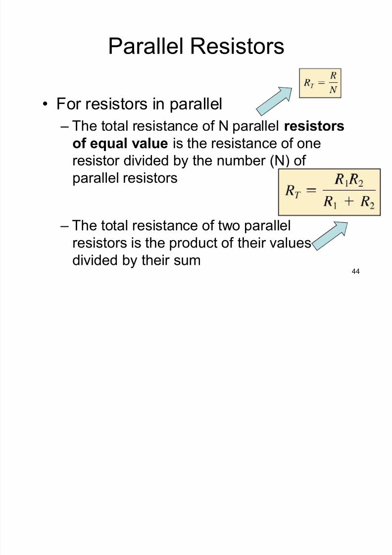
Parallel Resistors
For resistors in parallel
± The total resistance of N parallel resistors
of equal value is the resistance of oneresistor divided by the number (N) of
parallel resistors
± The total resistance of two parallel
resistors is the product of their values
divided by their sum
8/3/2019 Ddj2003 Notes Chap1 (Dc Circuits)
http://slidepdf.com/reader/full/ddj2003-notes-chap1-dc-circuits 45/69
45
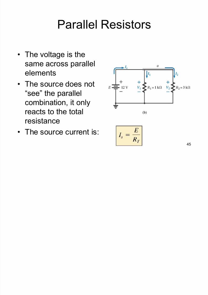
Parallel Resistors
The voltage is the
same across parallel
elements The source does not
³see´ the parallel
combination, it only
reacts to the totalresistance
The source current is:
8/3/2019 Ddj2003 Notes Chap1 (Dc Circuits)
http://slidepdf.com/reader/full/ddj2003-notes-chap1-dc-circuits 46/69
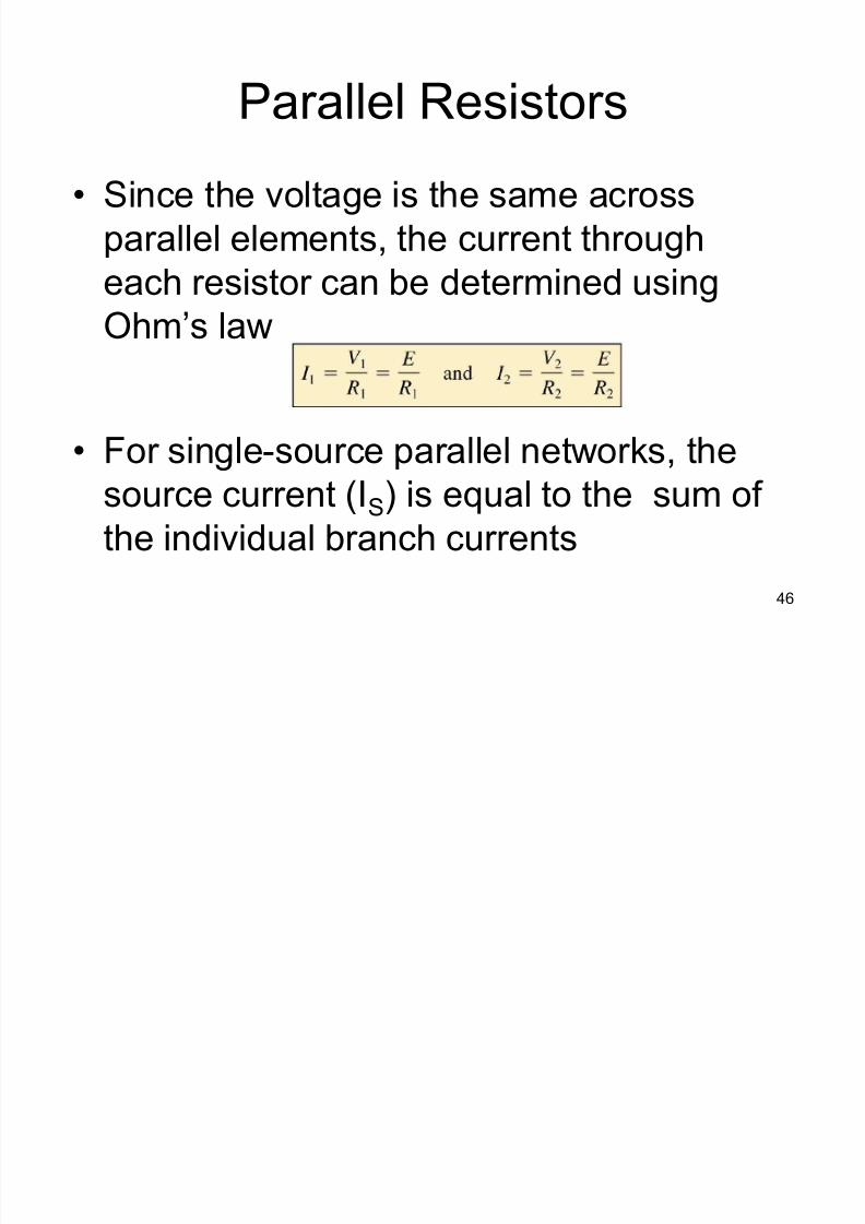
46
Parallel Resistors
Since the voltage is the same across
parallel elements, the current through
each resistor can be determined using
Ohm¶s law
For single-source parallel networks, thesource current (IS) is equal to the sum of
the individual branch currents

8/3/2019 Ddj2003 Notes Chap1 (Dc Circuits)
http://slidepdf.com/reader/full/ddj2003-notes-chap1-dc-circuits 47/69
47
Parallel Resistors
For parallel resistors, the greatest current
will exist in the branch with the least
resistance
± current always seeks the path of least
resistance
To measure current through a resistor in a
parallel circuit, break the connection at thepoint of interest and insert the ammeter
with the current entering the positive (red)
lead
8/3/2019 Ddj2003 Notes Chap1 (Dc Circuits)
http://slidepdf.com/reader/full/ddj2003-notes-chap1-dc-circuits 48/69
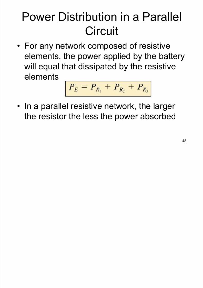
48
Power Distribution in a Parallel
Circuit For any network composed of resistive
elements, the power applied by the battery
will equal that dissipated by the resistive
elements
In a parallel resistive network, the larger the resistor the less the power absorbed
8/3/2019 Ddj2003 Notes Chap1 (Dc Circuits)
http://slidepdf.com/reader/full/ddj2003-notes-chap1-dc-circuits 49/69
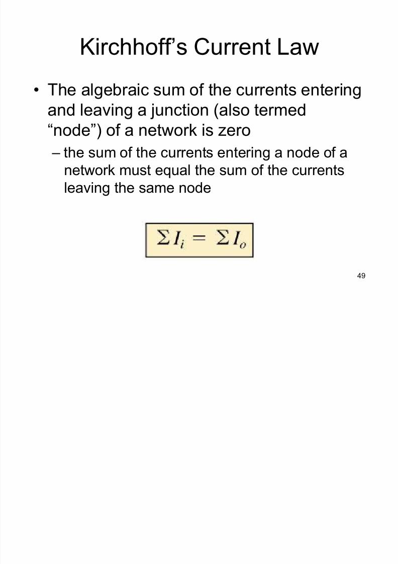
49
Kirchhoff¶s Current Law
The algebraic sum of the currents entering
and leaving a junction (also termed
³node´) of a network is zero
± the sum of the currents entering a node of a
network must equal the sum of the currents
leaving the same node
8/3/2019 Ddj2003 Notes Chap1 (Dc Circuits)
http://slidepdf.com/reader/full/ddj2003-notes-chap1-dc-circuits 50/69
50
Kirchhoff¶s Current Law
8/3/2019 Ddj2003 Notes Chap1 (Dc Circuits)
http://slidepdf.com/reader/full/ddj2003-notes-chap1-dc-circuits 51/69
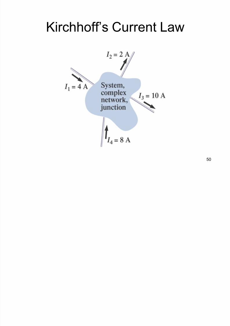
51
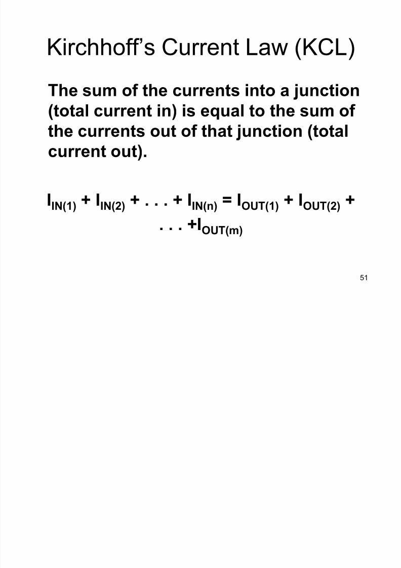
Kirchhoff¶s Current Law (KCL)
The sum of the currents into a junction
(total current in) is equal to the sum of
the currents out of that junction (total
current out).
IIN(1) + IIN(2) + . . . + IIN(n) = IOUT(1) + IOUT(2) +
. . . +IOUT(m)
8/3/2019 Ddj2003 Notes Chap1 (Dc Circuits)
http://slidepdf.com/reader/full/ddj2003-notes-chap1-dc-circuits 52/69
52
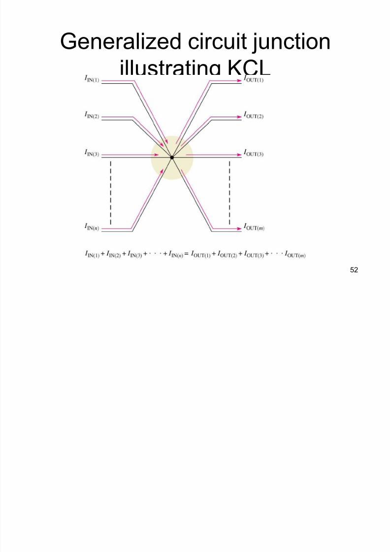
Generalized circuit junction
illustrating KCL

8/3/2019 Ddj2003 Notes Chap1 (Dc Circuits)
http://slidepdf.com/reader/full/ddj2003-notes-chap1-dc-circuits 53/69
53
Kirchhoff¶s Current Law
Kirchhoff¶s current Law (KCL) can be
stated another way:
The algebraic sum of all the currents
entering and leaving a junction is equal
to zero.
8/3/2019 Ddj2003 Notes Chap1 (Dc Circuits)
http://slidepdf.com/reader/full/ddj2003-notes-chap1-dc-circuits 54/69
54
Kirchhoff¶s Current Law
If the direction of the current is not known:
± make an assumption about the direction and
then check out the result
± if the result is negative, the wrong direction
was assumed
± if positive, the correct direction was assumed
± in either case, the magnitude of the currentwill be correct
8/3/2019 Ddj2003 Notes Chap1 (Dc Circuits)
http://slidepdf.com/reader/full/ddj2003-notes-chap1-dc-circuits 55/69
55
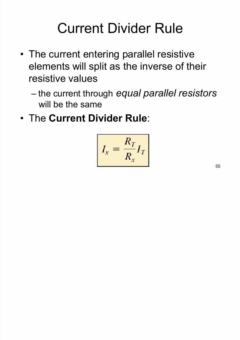
Current Divider Rule
The current entering parallel resistive
elements will split as the inverse of their
resistive values
± the current through equal parallel resistorswill be the same
The Current Divider Rule:
8/3/2019 Ddj2003 Notes Chap1 (Dc Circuits)
http://slidepdf.com/reader/full/ddj2003-notes-chap1-dc-circuits 56/69
56
Current Divider Rule
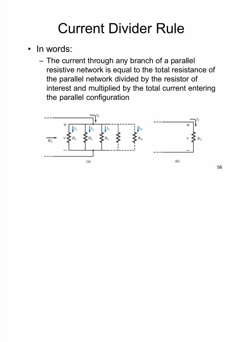
In words:
± The current through any branch of a parallel
resistive network is equal to the total resistance of
the parallel network divided by the resistor of
interest and multiplied by the total current enteringthe parallel configuration
8/3/2019 Ddj2003 Notes Chap1 (Dc Circuits)
http://slidepdf.com/reader/full/ddj2003-notes-chap1-dc-circuits 57/69
57
Current Divider Rule
The current through the smallest resistor
will be very close to the total current for a
parallel network if the other parallel
elements of the configuration are much
larger in magnitude
8/3/2019 Ddj2003 Notes Chap1 (Dc Circuits)
http://slidepdf.com/reader/full/ddj2003-notes-chap1-dc-circuits 58/69
58
Current Divider Rule
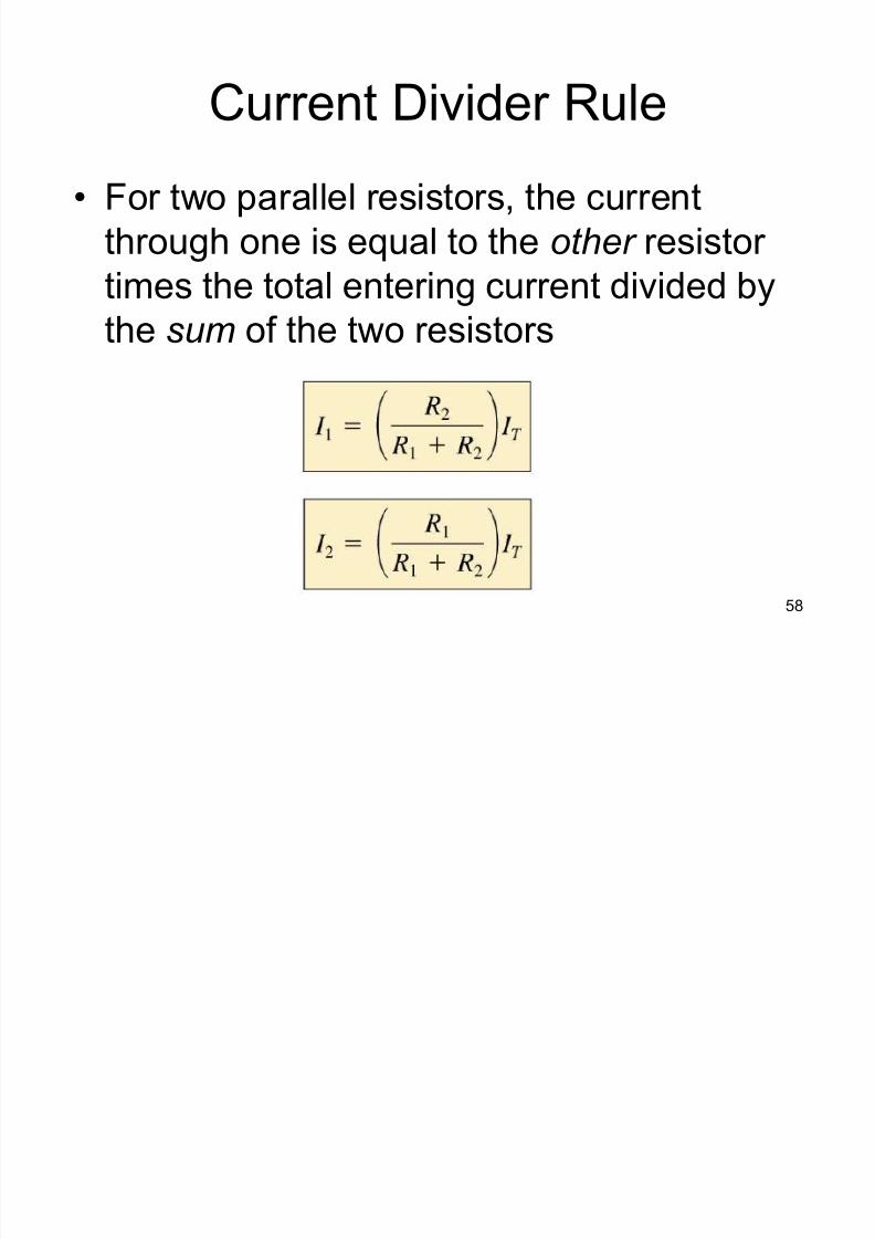
For two parallel resistors, the current
through one is equal to the other resistor
times the total entering current divided by
the sum of the two resistors
8/3/2019 Ddj2003 Notes Chap1 (Dc Circuits)
http://slidepdf.com/reader/full/ddj2003-notes-chap1-dc-circuits 59/69
59
Current Sources in Parallel
A current source is a type of energy
source that provides a constant current to
a load even if the resistance of that load
changes.
8/3/2019 Ddj2003 Notes Chap1 (Dc Circuits)
http://slidepdf.com/reader/full/ddj2003-notes-chap1-dc-circuits 60/69
60
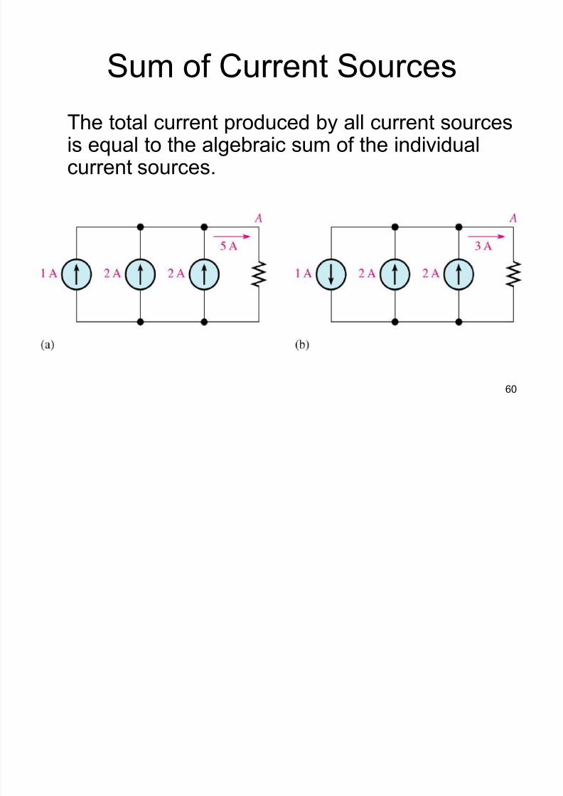
Sum of Current Sources
The total current produced by all current sourcesis equal to the algebraic sum of the individualcurrent sources.
8/3/2019 Ddj2003 Notes Chap1 (Dc Circuits)
http://slidepdf.com/reader/full/ddj2003-notes-chap1-dc-circuits 61/69
61
Voltage Sources in Parallel
Voltage sources can only be placed in
parallel if they have the same voltage
± the primary reason for placing two or more
batteries or supplies in parallel would be to
increase the current rating above that of a
single supply
± the total source current using Kirchhoff¶scurrent law is the sum of the rated currents of
each supply
8/3/2019 Ddj2003 Notes Chap1 (Dc Circuits)
http://slidepdf.com/reader/full/ddj2003-notes-chap1-dc-circuits 62/69
62
SERIES-PARALLEL CIRCUITS
8/3/2019 Ddj2003 Notes Chap1 (Dc Circuits)
http://slidepdf.com/reader/full/ddj2003-notes-chap1-dc-circuits 63/69
63
Series-Parallel Network
A series-parallel configuration is one that is
formed by a combination of series and parallel
elements
Analysis
± study the problem to determine an overall approach
± examine each region of the network independently
before tying them together in series-parallelcombinations
± redraw the network with reduced branches
± check that the solution is reasonable

8/3/2019 Ddj2003 Notes Chap1 (Dc Circuits)
http://slidepdf.com/reader/full/ddj2003-notes-chap1-dc-circuits 64/69
64
Reduce and Return Approach
Reduction phase
± combine series
resistors to form an
equivalent resistor ± combine parallel
resistors to establish
the total resistance
Return phase ± work back to the
desired voltage
8/3/2019 Ddj2003 Notes Chap1 (Dc Circuits)
http://slidepdf.com/reader/full/ddj2003-notes-chap1-dc-circuits 65/69
65
Reduce and Return Approach
The network is reduced to its simplest
form across the source, and the source
current is determined
The return phase is where the resulting
source current is used to work back to the
desired unknown
8/3/2019 Ddj2003 Notes Chap1 (Dc Circuits)
http://slidepdf.com/reader/full/ddj2003-notes-chap1-dc-circuits 66/69
66
Open Circuit
The most common failure in a series
circuit is an open.
When an open occurs in a series circuit,
all of the source voltage appears across
the open.
8/3/2019 Ddj2003 Notes Chap1 (Dc Circuits)
http://slidepdf.com/reader/full/ddj2003-notes-chap1-dc-circuits 67/69
67
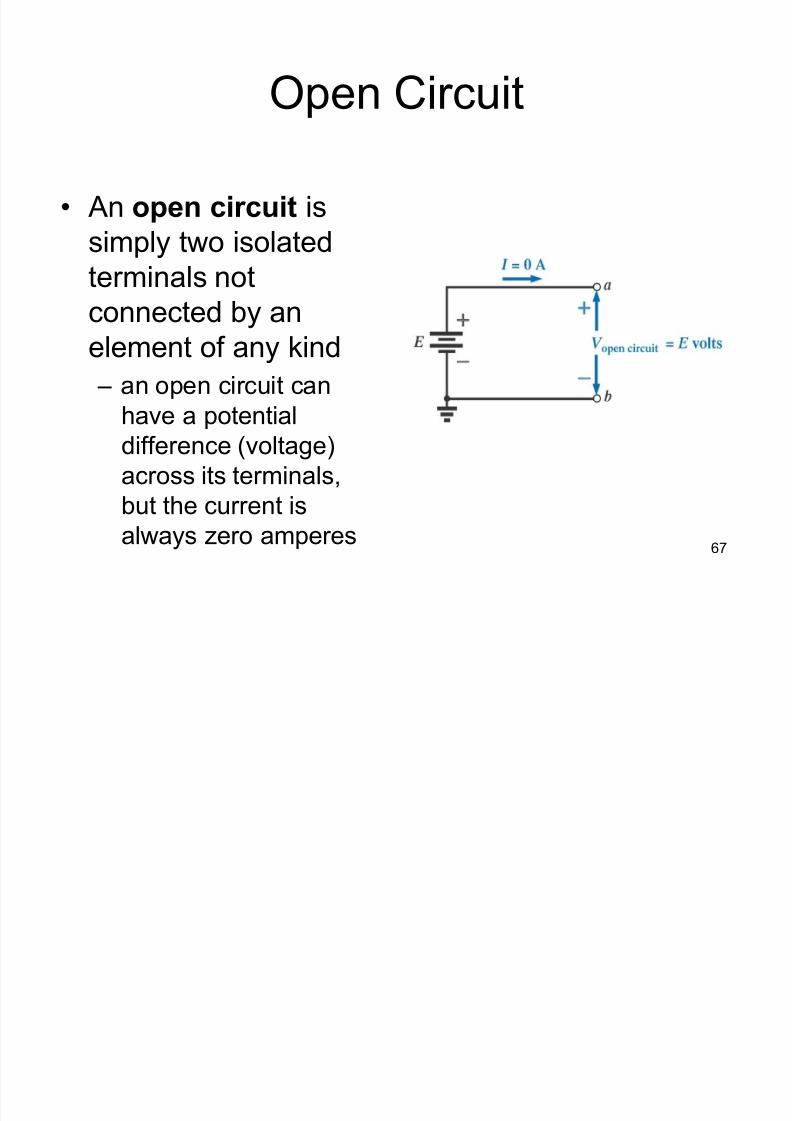
Open Circuit
An open circuit is
simply two isolated
terminals notconnected by an
element of any kind
± an open circuit can
have a potentialdifference (voltage)
across its terminals,
but the current is
always zero amperes
8/3/2019 Ddj2003 Notes Chap1 (Dc Circuits)
http://slidepdf.com/reader/full/ddj2003-notes-chap1-dc-circuits 68/69
68
Short Circuit
When there is a short, a portion of the
series resistance is bypassed, thus
reducing the total resistance.
A short in a series circuit results in more
current than normal.
8/3/2019 Ddj2003 Notes Chap1 (Dc Circuits)
http://slidepdf.com/reader/full/ddj2003-notes-chap1-dc-circuits 69/69
69
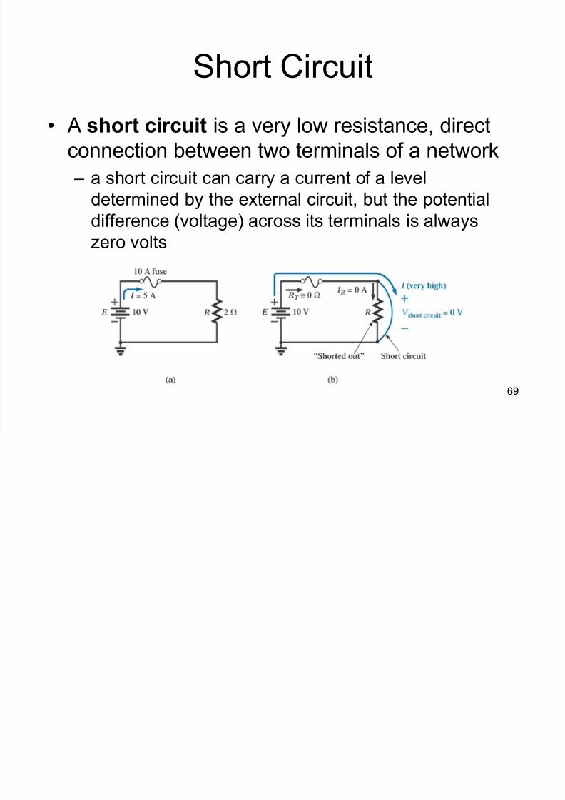
Short Circuit
A short circuit is a very low resistance, direct
connection between two terminals of a network
± a short circuit can carry a current of a level
determined by the external circuit, but the potentialdifference (voltage) across its terminals is always
zero volts