Embed Size (px)
Citation preview

Operation Manual OM 1077-1Group: Applied Air SystemsPart Number: OM 1077Date: July 2016
Maverick® I Package Air Conditioner DDC Rooftop Unit Controller
Heating & Cooling, Gas/Electric and Electric/Electric Models MPS 003B – 025B 3 to 25 Tonns [10.6 to 87.9 kW] R-410A Refrigerant

OM 1077-1 • MAVERICK I 2 www.DaikinApplied.com
Table of ConTenTs
Table of ConTenTs
Introduction. . . . . . . . . . . . . . . . . . . . . . . . . . . . . . . . . . 3General . . . . . . . . . . . . . . . . . . . . . . . . . . . . . . . . . . . . 3
Hazardous Information Messages . . . . . . . . . . . . . . 3Third party Building Management System . . . . . . . . 3BACnet® Communication Module . . . . . . . . . . . . . . 3LonMark® Communication Module . . . . . . . . . . . . . 3Programmable 24 Volt Thermostat . . . . . . . . . . . . . 4
Control Inputs and Outputs. . . . . . . . . . . . . . . . . . . . . 6Control Inputs . . . . . . . . . . . . . . . . . . . . . . . . . . . . . . . 6
Control Input Descriptions . . . . . . . . . . . . . . . . . . . . 6Control Outputs . . . . . . . . . . . . . . . . . . . . . . . . . . . . . . 8
Control Output Descriptions . . . . . . . . . . . . . . . . . . 8Unit Installation. . . . . . . . . . . . . . . . . . . . . . . . . . . . . . . 9
Controls using 24 VAC . . . . . . . . . . . . . . . . . . . . . . 9Controls using DC Analog Input/Outputs (Standard Low Voltage Multi-conductor Wire) . . . . 9Stand Alone with Thermostat . . . . . . . . . . . . . . . . 10Standalone with Zone Sensor and Time Clock . . . 10Standalone with Building Automation System . . . . 11Indoor Relative Humidity Sensor . . . . . . . . . . . . . . 12
Sequence of Operation . . . . . . . . . . . . . . . . . . . . . . . 13
User Interface . . . . . . . . . . . . . . . . . . . . . . . . . . . . . . . 17Keypad . . . . . . . . . . . . . . . . . . . . . . . . . . . . . . . . . . . 17General Information Screen . . . . . . . . . . . . . . . . . . . 19Unit Status Screen . . . . . . . . . . . . . . . . . . . . . . . . . . 19Effective Occupancy Screen . . . . . . . . . . . . . . . . . . . 20Temperature Screen . . . . . . . . . . . . . . . . . . . . . . . . . 21Set Points Screen . . . . . . . . . . . . . . . . . . . . . . . . . . . 21Economizer . . . . . . . . . . . . . . . . . . . . . . . . . . . . . . . . 22Integrated Furnace Control Screen. . . . . . . . . . . . . . 24Time Delays Screen . . . . . . . . . . . . . . . . . . . . . . . . . 25Humidity Control . . . . . . . . . . . . . . . . . . . . . . . . . . . . 26
Enable rh Control . . . . . . . . . . . . . . . . . . . . . . . . . . 26rh Set Point . . . . . . . . . . . . . . . . . . . . . . . . . . . . . . 26Indoor rh. . . . . . . . . . . . . . . . . . . . . . . . . . . . . . . . . 27
Variable Frequency Drive . . . . . . . . . . . . . . . . . . . . . 28Status Line . . . . . . . . . . . . . . . . . . . . . . . . . . . . . . . 28VFD Low Fan Speed . . . . . . . . . . . . . . . . . . . . . . . 28VFD 1st Stage Cool . . . . . . . . . . . . . . . . . . . . . . . . 28VFD Current Speed . . . . . . . . . . . . . . . . . . . . . . . . 28
Alarm List . . . . . . . . . . . . . . . . . . . . . . . . . . . . . . . . . . 29Quick Start . . . . . . . . . . . . . . . . . . . . . . . . . . . . . . . . . 34
Units with Thermostat Control . . . . . . . . . . . . . . . . . . 34Wiring Diagrams. . . . . . . . . . . . . . . . . . . . . . . . . . . . . 35Data . . . . . . . . . . . . . . . . . . . . . . . . . . . . . . . . . . . . . . . 47

InTroduCTIon
www.DaikinApplied.com 3 OM 1077-1 • MAVERICK I
InTroduCTIon
GeneralRead this manual and any instructions packaged with separate equipment prior to installation. Give this manual to the owner and explain its provisions. The owner should retain this manual for future reference.
Unit ManualRooftop unit control configuration OM 1077BACnet Communication Module IM 1000LonWorks Communication Module IM 999Field Installed Accessories IM 921Maverick I, 3 to 5 ton Installation and Maintenance IM 970Maverick I, 6 to 12 ton Installation and Maintenance IM 971Maverick I, 15 to 25 ton Installation and Maintenance IM 972
Hazardous Information Messages DANGER
These instructions are intended as an aid to qualified service personnel for proper installation, adjustment, and operation of this unit. Read these instructions thoroughly before attempting installation, adjustment, or operation. Failure to follow these instructions can result in improper installation, adjustment, service or maintenance, possibly resulting in fire, electrical shock, property damage, personal injury, or death.
DANGERBefore beginning any modification, be sure main disconnect switch is in the “off” position. Failure to do so can cause electrical shock resulting in property damage, personal injury or death. Tag disconnect with a suitable warning label.
CAUTIONStatic sensitive components. Discharge any static electrical charge by touching the bare metal inside the control panel before performing any service work. Never unplug cables, circuit board terminal blocks, or power plugs while power is applied to the panel.
NOTICE
This equipment generates, uses, and can radiate radio frequency energy and; if not installed and used in accordance with this instruction manual, may cause interference to radio communications. It has been tested and found to comply with the limits for a Class A digital device, pursuant to part 15 of the FCC rules. These limits are designed to provide reasonable protection against harmful interference when the equipment is operated in a commercial environment. Operation of this equipment in a residential area is likely to cause harmful interference in which case the user will be required to correct the interference at their own expense.
The Maverick I 3 to 25 ton Package has a Rooftop Unit Controller factory mounted and wired in their respective control panel. The DDC Controller is a solid-state microprocessor-based control board that provides flexible control and extensive diagnostics for all unit functions. The DDC Controller through proportional/integral control algorithms perform specific unit functions that govern unit operation in response to; zone conditions, system temperatures, ambient conditions and electrical inputs. The DDC Controller features an LCD display and a five-button keypad for local configuration and direct diagnosis of the system.
The Maverick I 3 to 25 ton Package Air Conditioner with integral Rooftop Unit Controller (DDC Controller) is specifically designed to be applied in three distinct applications:
Third party Building Management System In an application where a third party building management is in use or will be incorporated the Maverick I is communication compatible with the system that supports the BACnet Application Specific Controller device profile, LonMark Space Comfort Controller functional profile. This is accomplished with a field installed BACnet or LonMark communication module. The BAS system provides the schedule functions for the DDC controller.
BACnet® Communication Module The BACnet Communication Module allows communication between the DDC Controller and the BACnet network. The communication module translates input and output variables between the DDC Controller protocol and the BACnet protocol.
The BACnet Communication Module is compatible with MSTP EIA-485 daisy chain networks communicating at 38.4 bps. It is compatible with twisted pair, shielded cables.
See IM 1000 for full documentation
lonMark® Communication Module Communication module translates input and output variables between the DDC Controller protocol and the LonTaLk protocol. The LonTaLk Communication Module has been developed to communicate with building automation systems that support the LonMark Space Comfort Controller (SCC).
The LonMark Communication Module utilizes an FTT-10A free topology transceiver communicating at 78.8 kbps. It is compatible with Echelon qualified twisted pair cable, Belden 8471 or NEMA Level 4 cables. The Module can communicate up to 1640 ft. with no repeater. The LonWorks limit of 64 nodes per segment applies to this device.
See IM 999 for full documentation
OM 1077-1 • MAVERICK I 4 www.DaikinApplied.com
InTroduCTIon
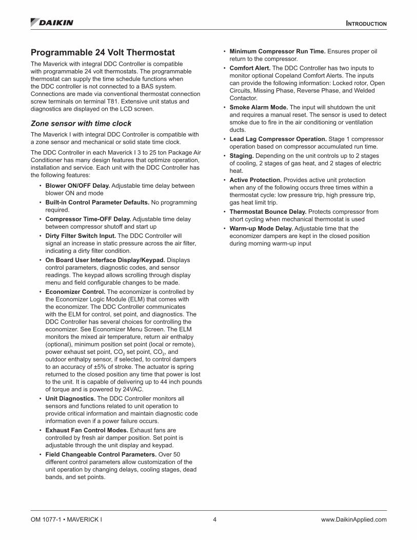
Programmable 24 Volt Thermostat The Maverick with integral DDC Controller is compatible with programmable 24 volt thermostats. The programmable thermostat can supply the time schedule functions when the DDC controller is not connected to a BAS system. Connections are made via conventional thermostat connection screw terminals on terminal T81. Extensive unit status and diagnostics are displayed on the LCD screen.
Zone sensor with time clock The Maverick I with integral DDC Controller is compatible with a zone sensor and mechanical or solid state time clock.
The DDC Controller in each Maverick I 3 to 25 ton Package Air Conditioner has many design features that optimize operation, installation and service. Each unit with the DDC Controller has the following features:
• Blower ON/OFF Delay. Adjustable time delay between blower ON and mode
• Built-in Control Parameter Defaults. No programming required.
• Compressor Time-OFF Delay. Adjustable time delay between compressor shutoff and start up
• Dirty Filter Switch Input. The DDC Controller will signal an increase in static pressure across the air filter, indicating a dirty filter condition.
• On Board User Interface Display/Keypad. Displays control parameters, diagnostic codes, and sensor readings. The keypad allows scrolling through display menu and field configurable changes to be made.
• Economizer Control. The economizer is controlled by the Economizer Logic Module (ELM) that comes with the economizer. The DDC Controller communicates with the ELM for control, set point, and diagnostics. The DDC Controller has several choices for controlling the economizer. See Economizer Menu Screen. The ELM monitors the mixed air temperature, return air enthalpy (optional), minimum position set point (local or remote), power exhaust set point, CO2 set point, CO2, and outdoor enthalpy sensor, if selected, to control dampers to an accuracy of ±5% of stroke. The actuator is spring returned to the closed position any time that power is lost to the unit. It is capable of delivering up to 44 inch pounds of torque and is powered by 24VAC.
• Unit Diagnostics. The DDC Controller monitors all sensors and functions related to unit operation to provide critical information and maintain diagnostic code information even if a power failure occurs.
• Exhaust Fan Control Modes. Exhaust fans are controlled by fresh air damper position. Set point is adjustable through the unit display and keypad.
• Field Changeable Control Parameters. Over 50 different control parameters allow customization of the unit operation by changing delays, cooling stages, dead bands, and set points.
• Minimum Compressor Run Time. Ensures proper oil return to the compressor.
• Comfort Alert. The DDC Controller has two inputs to monitor optional Copeland Comfort Alerts. The inputs can provide the following information: Locked rotor, Open Circuits, Missing Phase, Reverse Phase, and Welded Contactor.
• Smoke Alarm Mode. The input will shutdown the unit and requires a manual reset. The sensor is used to detect smoke due to fire in the air conditioning or ventilation ducts.
• Lead Lag Compressor Operation. Stage 1 compressor operation based on compressor accumulated run time.
• Staging. Depending on the unit controls up to 2 stages of cooling, 2 stages of gas heat, and 2 stages of electric heat.
• Active Protection. Provides active unit protection when any of the following occurs three times within a thermostat cycle: low pressure trip, high pressure trip, gas heat limit trip.
• Thermostat Bounce Delay. Protects compressor from short cycling when mechanical thermostat is used
• Warm-up Mode Delay. Adjustable time that the economizer dampers are kept in the closed position during morning warm-up input

InTroduCTIon
www.DaikinApplied.com 5 OM 1077-1 • MAVERICK I
Figure 1: Controller Component Locations
Item DescriptionP1 Electric heat connectorFan Indoor blower motor connectorCC1 Compressor 1 connectorCC2 Compressor 2 connector
P3 Reversing valve 1, Reversing valve 2, Outdoor Coil temperature sensor 1, Outdoor Coil temperature sensor 2, Outdoor Fan 1, and Outdoor Fan 2 connector
P4 Motorized Fresh Air Damper, Economizer Logic Module (ELM), and Smoke Detector connectorP5 Return air temperature sensor, Fan proving switch, Clogged filter switch, and Discharge air temperature sensor connector
P6 Freeze sensor 1, Freeze sensor 2, Outside air temperature sensor, High pressure switch 1, High pressure switch 2, Low pressure switch 1, and Low pressure switch 2 connector
P10 RJ11 connector for factory run testP11 Configurable pins used to set unit typeP12 Test Pins to force defrost for heat pump modelsP13 Connector to Integrated Furnace Control (IFC) – provides power and communication between DDC Controller and IFCT7 Field Installed Space Temperature Sensor with Set Point and Override, Field configurable 1, and Field configurable 2 terminal block
T14 Not supportedT81 Thermostat screw terminals Common terminals Terminals used for 24 volt common connections & power supply
24 Volt terminals Terminals used for 24 volt hot connections & power supplyComfort Alert Terminals used to connect a Comfort Alert module
LED4 LED4 is blinking when the control has an ALARM present, solid when power is applied.MOD1 LED MOD1 LED blinks when the control is communicating on the internal network between the IFC and/or economizerMOD2 LED MOD2 LED blinks when the control is communicating between the DDC Controller and field installed communication card
P1
Common
24 VAC
P3
P4
P5P11
Keypad
LED 4
MOD1
P10
T14 MOD2P12
T7T81
Fan, CC1, CC2, Common
Comfort Alert
LCD DisplayP6P13

OM 1077-1 • MAVERICK I 6 www.DaikinApplied.com
ConTrol InpuTs and ouTpuTs
ConTrol InpuTs and ouTpuTs
Control InputsTable 1: Control Inputs
Item Description Type Option 1 ST - Space temperature Thermistor 10k Ω Field Installed (optional) 2 RAT - Return Air Temperature Thermistor 10k Ω Factory Installed 3 SAT - Supply Air Temperature Thermistor 10k Ω Factory Installed 4 OAT - Outside Air Temperature Thermistor 10k Ω Factory Installed 5 FS1 - Freeze Stat Thermistor 10k Ω Factory Installed 6 FS2 - Freeze Stat Thermistor 10k Ω Factory Installed 7 Field Configurable input #1 Thermistor 10k Ω Field Installed (optional) 8 Field Configurable input #2 Analog input Field Installed (optional) 9 SPA - Set point Adjustment Resistance input Field Installed (optional)
10a G - Thermostat fan input 24VAC Field Installed (optional) 11† Y1 - Thermostat 1st stage compressor 24VAC Field Installed (optional) 12 Y2 - Thermostat 2nd stage compressor 24VAC Field Installed (optional) 13 W1 - Thermostat heating demand 24VAC Field Installed (optional) 14 W2 - Thermostat heating demand 24VAC Field Installed (optional) 15 HP1 - High Pressure Switch 1 24VAC Factory Installed 16 LP1 - Low Pressure Switch 1 24VAC Factory Installed 17† HP2 - High Pressure Switch 2 24VAC Factory Installed 18 LP2 - Low Pressure Switch 2 24VAC Factory Installed 19 Smoke Detector 24VAC Factory or Field Installed 20 FP - Fan proving 24VAC Factory Installed 21 CFS - Clogged Filter Switch 24VAC Factory Installed 22 Occupied input 24VAC Field Installed (optional) 23 L1 - Comfort Alert 1 Pulsed 24VDC Factory or Field Installed (optional) 24 L2 - Comfort Alert 2 Pulsed 24VDC Factory or Field Installed (optional) 25 Configuration pins Polarized Plug P11 Factory Installed
a. Heat Pump Only †
Control Input Descriptions(1) ST - Space temperature. The space temperature sensor is used to measure the building zone temperature. Sensors should be located on an interior building wall.
(2) RAT - Return Air Temperature. The DDC Controller has a return air temperature input. This input is used to monitor system functionality and to provide diagnostics on how the system is operating. This sensor input can be used in place of the space temperature input. It also acts as a backup in case of a space temperature sensor failure.
(3) SAT - Supply Air Temperature. The DDC Controller has a supply air temperature input. This input is used to monitor system functionality and to provide diagnostics on how the system is operating.
(4) OAT - Outside Air Temperature. The outdoor air temperature sensor is factory installed in the unit to monitor the outside temperature. This temperature is used to control the economizer.
(5) FS1 - Freeze Stat. When the thermistor reads a temperature below 37°F continuously for 15 minutes, the control will shutdown compressor #1 and continue to run the indoor blower. The system will return to normal operation when the thermistor reads a temperature above 42°F for 15 minutes.
(6) FS2 - Freeze Stat. When the thermistor reads a temperature below 37°F continuously for 15 minutes, the control will shutdown compressor #2 and continue to run the indoor blower. The system will return to normal operation when the thermistor reads a temperature above 42°F for 15 minutes.
(7) Field Configurable input #1. Used for custom installation of a 10K ohm temperature sensor (e.g. discharge air temperature sensor installed in supply duct).
(8) Field Configurable input #2. Used for custom installation of an analog input (e.g. 0-10VDC input from outdoor airflow monitoring station).
(9) SPA - Set point Adjustment. If the set point adjustment is enabled, then the control will consider the hard wired potentiometer input to determine occupied set points only. If the remote set point adjustment is enabled but the input reads an invalid number, the control will default back to the occupied set point selection.

ConTrol InpuTs and ouTpuTs
www.DaikinApplied.com 7 OM 1077-1 • MAVERICK I
(10) G - Thermostat fan input. This is a 24 volt input that is used to control the indoor fan when the DDC Controller is used in conjunction with a thermostat.
(11) Y1 - Thermostat 1st stage compressor. This is a 24 volt input that is used to control the first stage of mechanical cooling when the DDC Controller is used in conjunction with a thermostat.
(12) Y2 - Thermostat 2nd stage compressor. This is a 24 volt input that is used to control the second stage of mechanical cooling when the DDC Controller is used in conjunction with a thermostat.
(13) W1 - Thermostat heating demand. This is a 24 volt input that is used to control the first stage of heating (electric heat or gas heat) when the DDC Controller is used in conjunction with a thermostat.
(14) W2 - Thermostat heating demand. This is a 24 volt input that is used to control the second stage of heating (electric heat or gas heat) when the DDC Controller is used in conjunction with a thermostat.
(15 &17) HP1, HP2 - High Pressure Switch 1 & 2. When the HPC is opened, the compressor for that circuit is turned OFF. The compressor will not be allowed to restart for a minimum of 3 minutes. If three consecutive open conditions occur during an active call for operation, the compressor will be locked out, a diagnostic will appear on the LCD display and communicated to the network if applicable. Cycling the call for operation will restart the compressor. On dual compressor units only the affected compressor circuit is locked out.
(16 & 18) LP1, LP2 - Low Pressure Switch 1 & 2. When the LPC is opened, the compressor for that circuit is turned OFF. The compressor will not be allowed to restart for a minimum of 3 minutes. The low pressure switch is ignored during defrost and for the first 90 seconds of compressor run time. If three consecutive open conditions occur during an active call for operation, the compressor will be locked out, a diagnostic will appear on the LCD display and communicated to the Network if applicable. Cycling the call for operation will restart the compressor. On dual compressor units only the affected compressor circuit is locked out.
(19) Smoke Detector. The sensor is only applicable on units equipped with a smoke detector. The input will shutdown the unit and requires a manual reset. The sensor is used to detect smoke due to fire in the air condition or ventilation ducts.
(20) FP - Fan proving. The unit mounted fan proving switch monitors the pressure differential across the unit blower to detect when the indoor fan is blowing air. A diagnostic signal is sent to the LCD display if the pressure differential indicates that the indoor blower is not operating. The control will also monitor the system and if the blower is running and is not required a fault will be sent to the DDC Controller.
(21) CFS - Clogged Filter Switch. The unit mounted clogged filter switch monitors the pressure differential across the return air filters. It is mounted in the filter section and is connected to the DDC Controller. A diagnostic signal is sent to the LCD display if the pressure differential across the filters is at least 0.5" w.c. The contacts will automatically open when the pressure differential across the filters decreases to approximately 0.4" w.c., the clogged filter output is operating, and the clogged filter switch has been closed for at least 2 minutes. The system will continue to operate regardless of the status of the filter switch.
(22) Occupied input (OC). This is a 24 volt input that is used to control the occupancy (occupied or unoccupied mode) when the DDC Controller is used in conjunction with a zone sensor and solid state time clock.
(23 & 24) L1, L2 - Comfort Alert. The DDC Controller has two inputs to monitor up to two compressor circuits using optional Copeland Comfort Alerts. The inputs can provide the following information: Locked rotor, Open Circuits, Missing Phase, Reverse Phase, and Welded Contactor. NOTE: The Comfort Alert sends the Open Circuit Alarm (code 5) only after the fault has been sensed for a minimum of 4 hours.
(25) Configuration pins (P11). The DDC Controller features a 7 pin header (P11) on board for the connection of a configuration key. This 7-position connector allows the controller to determine the unit application mode without a menu entry. Table 2 describes the connections necessary for each one of the possible options. The configuration connector provides a quick and safe way of replacing boards while keeping the proper configuration of the unit.
Table 2: Configuration Connector Parameters
P11 – Unit configuration 1 2 3 4 5 6 7Cooling only (default for 3-25T) DefaultSingle stage Cooling with 2 stages EH x xSingle stage G/E(cool) with 1 stage GH x xSingle stage G/E(cool) with 2 stages GH x x2 stages cool with 2 stages EH x x2 stages G/E(cool) with 2 stages GH x xSelection is made through the display x x x x

OM 1077-1 • MAVERICK I 8 www.DaikinApplied.com
ConTrol InpuTs and ouTpuTs
Control OutputsTable 3: Control Outputs
Item Description Type Option1 CC1 - Compressor output 1 24VAC 1.5A @ 24VAC, pilot duty2 CC2 - Compressor output 2 24VAC 1.5A @ 24VAC, pilot duty3 W1 - Heat output 24VAC 1.5A @ 24VAC, pilot duty4 W2 - Heat Output 24VAC 1.5A @ 24VAC, pilot duty5 G - Fan Output 24VAC 1.5A @ 24VAC, pilot duty6 L - thermostat signal 24VAC 25mA loading
Table 4: Thermostat Options
Device Part Number Description Stand alone 24V thermostat / touch screen 113129801 Up to 2-heat / 2-cool
Stand alone 24V thermostat 113129901 Up to 2-heat / 2-cool
Table 5: Zone Sensor Module Wire Guide
Device Part Number
Wire Gauge Conductors Type Listings
Wall mounted sensor with tenant override 113117701 18 3 Solid
18 AWG 3/C CL2P Thermostat
Wall mounted sensor with space point adjustment
113117701 18 3 Solid18 AWG 3/C CL2P Thermostat
Control Output Descriptions (1) CC1 - Compressor output 1. The DDC Controller can control the compressor contactors. The DDC Controller can monitor the system and respond to system faults and comfort alert inputs to shut down the compressors in the event of a failure.
(2) CC2 - Compressor output 2. The DDC Controller can control the compressor contactors. The DDC Controller can monitor the system and respond to system faults and comfort alert inputs to shut down the compressors in the event of a failure.
(3) W1 - Heat output. The DDC Controller has two outputs to control resistance electric heat.
(4) W2 - Heat Output. The DDC Controller has two outputs to control resistance electric heat.
(5) G - Fan Output. The DDC Controller can control the indoor fan by use of a fan relay.
(6) L - Thermostat signal. The “L” terminal will output a flash code to an indoor 24 V thermostat equipped with an “L” terminal.

unIT InsTallaTIon
www.DaikinApplied.com 9 OM 1077-1 • MAVERICK I
unIT InsTallaTIon
DANGERBefore beginning any modification, be sure main disconnect switch is in the “OFF” position. Disconnect all electric power, including remote disconnect before servicing. Failure to do so can cause electrical shock resulting in property damage, personal injury or death. Follow proper lockout/tag out procedures to ensure the power cannot be inadvertently energized.
IMPORTANTThe DDC Controller is shipped with the control disabled so units do not accidentally energize during installation. The commissioning of the rooftop unit therefore requires the configuration of the Occupied Mode menu prior to initial startup. See Effective Occupancy on page 20.
The unit DDC Controller must have a thermostat or zone sensor input in order to operate the unit. If the zone sensor is not present, or has failed, the unit will use the return air temperature sensor to maintain the occupied set point. The flexibility of the unit mode capabilities depends upon the type of zone sensor or thermostat selected to interface with the DDC controller.
The descriptions of the following basic Input Devices used within the DDC controller network are to acquaint the operator with their function as they interface with the various modules. Refer to the unit’s electrical schematic for the specific module connection.
The following controls are available from the factory for field installation.
Controls using 24 VAC Before installing any connecting wiring, refer to the unit installation manual for AC conductor sizing guidelines “Field Wire Size For 24 Volt Thermostat Circuits”, for the electrical access locations provided on the unit, and;
• Use copper conductors unless otherwise specified. • Ensure that the AC control wiring between the controls
and the unit’s termination point does not exceed three (3) ohms per conductor for the length of the run.
NOTE: Note: Resistance in excess of 3 ohms per conductor may cause component failure due to insufficient AC voltage supply.
• Be sure to check all loads and conductors for grounds, shorts, and mis-wirings.
• Do not run the AC low voltage wiring in the same conduit with the high voltage power wiring.
• Some thermostat wire insulation has a voltage rating less than the line voltage. Route Thermostat Wire behind low voltage shield during unit installation per Figure 2. This is necessary to meet National Electrical Code (NEC) and UL 1995 requirements for separation of high and low voltage circuits.
Controls using DC Analog Input/Outputs (Standard Low Voltage Multi-conductor Wire) Before installing any connecting wiring between the unit and components utilizing a DC analog input/output signal, refer to the unit installation manual for the electrical access locations provided on the unit.
• Use shielded cable for high EMI environments. • Note: Resistance in excess of 2.5 ohms per conductor
can cause deviations in the accuracy of the controls. • Ensure that the wiring between controls and the unit’s
termination point does not exceed two and a half (2.5) ohms per conductor for the length of the run.
• Do not run the electrical wires transporting DC signals in or around conduit housing high voltage wires.
• Most sensor wire insulation has a voltage rating less than the line voltage. Route Zone Sensor and Network Cable behind low voltage shield during unit installation per Figure 2. This is necessary to meet NEC and UL 1995 requirements for separation of high and low voltage circuits.
Figure 2: Low Voltage Shielding
Conduit for Low Voltage Conductors
Sheilding for Low Voltage Conductors

OM 1077-1 • MAVERICK I 10 www.DaikinApplied.com
unIT InsTallaTIon
Stand Alone with Thermostat Once Occupied Mode is set to “Control by Thermostat” the DDC Controller will follow the commands from a regular 24VAC thermostat, according to the following convention:
• •G - Indoor fan • •Y1 - First stage of compressor • Y2 - Second Stage of compressor • B - Not Used • W1 - First Stage Auxiliary heat (electric or gas) • W2 - Second Stage Auxiliary heat (electric or gas) • L - Comfort Alert signal (output) • R & C - 24VAC
Figure 3: Thermostat Inputs and Outputs
Standalone with Zone Sensor and Time Clock If Occupied Mode is set to any of the options other than “Off” and “Control By Thermostat”, the control will operate in Stand Alone mode or network using its local temperature sensors to determine demand. The system can be set up with a zone sensor to determine heat or cool demand and a solid state time clock to determine occupancy. (See Occupied Mode on page 20)
Figure 4: Standalone with Zone Sensor and Time Clock
+24VAC1st Stage
Compressor2nd Stage
CompressorIndoor Fan24V Common
1st Stage Heat
2nd Stage Heat
Occupancy Signal
ReversingValve
Comfort Alert
10k Thermistor
2k
5k
10k PotSetpoint Adj.
OverrideButton
Zone Sensor
Time Clock

unIT InsTallaTIon
www.DaikinApplied.com 11 OM 1077-1 • MAVERICK I
Standalone with Building Automation System If Occupied Mode is set to any of the options other than “OFF” and “Control By Thermostat”, the control will operate in Stand Alone mode or network using its local temperature sensors to determine demand. The system can be set up with a zone sensor, 910108514 or 910108214 communication card, and 2nd-party building automation system that will be controlled from a central location.
Figure 5: Zone Sensor with Building Automation System
LONWorks Daughter BoardBACnet Daughter Board
10k Thermistor
2k
5k
10k PotSetpoint Adj.
OverrideButton
Zone Sensor
OM 1077-1 • MAVERICK I 12 www.DaikinApplied.com
unIT InsTallaTIon
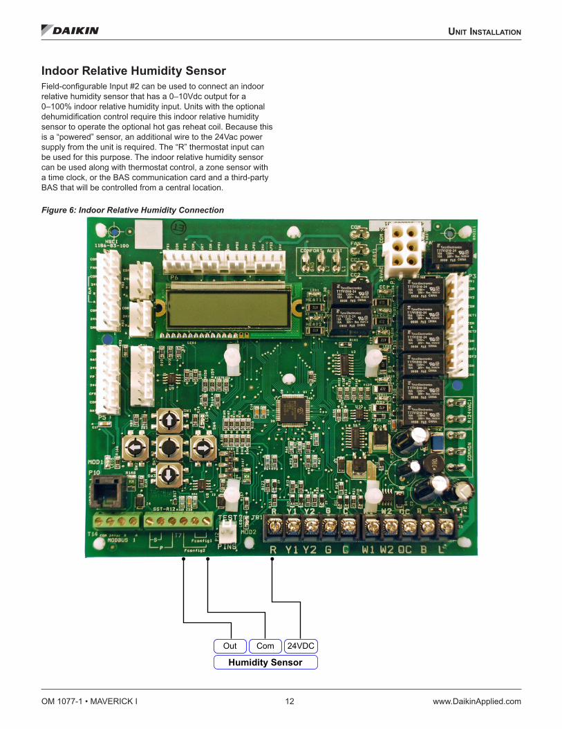
Indoor Relative Humidity SensorField-configurable Input #2 can be used to connect an indoor relative humidity sensor that has a 0–10Vdc output for a 0–100% indoor relative humidity input. Units with the optional dehumidification control require this indoor relative humidity sensor to operate the optional hot gas reheat coil. Because this is a “powered” sensor, an additional wire to the 24Vac power supply from the unit is required. The “R” thermostat input can be used for this purpose. The indoor relative humidity sensor can be used along with thermostat control, a zone sensor with a time clock, or the BAS communication card and a third-party BAS that will be controlled from a central location.
Figure 6: Indoor Relative Humidity Connection
Out Com 24VDC
Humidity Sensor

sequenCe of operaTIon
www.DaikinApplied.com 13 OM 1077-1 • MAVERICK I
sequenCe of operaTIon
IMPORTANTThe DDC Controller is shipped with the control disabled so units do not accidentally energize during installation. The commissioning of the rooftop unit therefore requires the configuration of the Occupied Mode menu prior to initial startup. See Occupied Mode on page 20.
Cooling When the DDC Controller receives a call for cooling via thermostat or zone sensor compressor 1 energizes. After the indoor fan on delay (1-180 sec / default 10 sec) the indoor fan energizes. The indoor fan on delay starts when the call for cooling is initiated.
When used in local zone sensor mode of operation, the DDC Controller satisfies the set point using all or a partial number of stages available. When cooling demand exists, the DDC Controller will stage up in the following order: Economizer, First Stage Cooling, and Second Stage Cooling based on demand.
When used in local thermostat mode of operation, the DDC Controller allows the thermostat to control the demand for cooling. When cooling demand exists, the DDC Controller will stage up in the following order: Economizer, First Stage Cooling. Only two stages will be allowed to energize, so if the economizer is active then the first stage mechanical cooling will become second stage and second stage mechanical cooling will not be used.
Heat When in heating mode of operation, the DDC Controller satisfies the set point using all or a partial number of stages available. When heating demand exists, the DDC Controller will utilize heat sources in the following order of priority as available: Gas Heat and Electric.
When the heat demand requires multiple heating outputs at the same time, a minimum staging delay of 5 seconds between energizing and de-energizing heating outputs is necessary to prevent the inrush current startup of multiple loads. The inter stage is adjustable between 5 and 50 seconds.
The source of demand, like the other modes of operation, is a result of one of either thermostat or remote sensors.
Integrated Furnace Control The Integrated Furnace Control (IFC) is external to the DDC Controller, and on units so equipped, controls the furnace and gas valve operation based on signals from the DDC controller. The IFC also provides furnace troubleshooting information via LED flashing fault codes. When a fault condition exists, the LED (see Figure 7) flashes the number of times indicated by the code number, pauses, and repeats.
Figure 7: Integrated Furnace Control Status LED
Table 6: Integrated Furnace Control Fault Codes
Code Meaning1 Failure To Detect Or Sustain Flame2 Pressure Switch Or Inducer Problem Detected3 High Limit Protection Deice Open4 Gas Valve Not Energized Or No “W” Signal5 Flame Toll Out Switch Open
Call for Heat After a call for heat the IFC checks to ensure the high temperature limit and rollout switches are closed. If either is open, the IFC responds with a fault code. If high limit and rollout switches are closed, the IFC checks that both pressure switches are open. If either pressure switch is closed, the IFC will respond with a fault code and it will flash code “2” on the LED, waiting indefinitely for both pressure switches to open. If both pressure switches are open, the IFC proceeds to prepurge.
LED

OM 1077-1 • MAVERICK I 14 www.DaikinApplied.com
sequenCe of operaTIon
Pre-Purge The IFC energizes the low inducer motor, flashes code “2” on LED, and waits for the low pressure switch to close. If the low pressure switch does not close within 3 minutes, the control will energize the high inducer and wait for both pressure switches to close. The IFC will light on high fire and remain on high fire for the remainder of the heat cycle.
When the low pressure switch has closed, the IFC stops flashing the LED and begins timing the 30 second pre-purge period. If flame is sensed as present during pre-purge, the IFC restarts the pre-purge time to require a full pre-purge after flame is removed. When pre-purge time has expired, the IFC begins the ignition trial.
Ignition Trial The IFC energizes the gas valve and spark. The IFC ignores flame sense for the first 2 seconds of the ignition trial. If flame is not established within 7 seconds, the gas valve and spark is de-energized and the IFC goes to an inter-purge. If flame is established, the spark is de-energized, the IFC energizes the high inducer (low inducer remains energized) and begins heat blower on delay.
Heat Blower On-Delay The control waits for 45 second heat fan on delay and then energizes the indoor blower heat speed. If the blower is already energized by a call for cooling or continuous fan, or in a blower off delay period, the on delay is skipped and the blower remains energized. After the blower on delay time is complete, the control goes to high fire warm-up mode.
The high pressure switch is ignored during the heat blower on delay to give time for the high pressure switch to close if lighting on low fire.
High-fire Warm-up The IFC remains on high fire for 120 seconds after flame is established. If the DDC Controller is calling for 2nd stage heat, the IFC remains in high heat. If the IFC lit on high fire because the low pressure switch did not close within 3 minutes, then the IFC remains on high fire for the entire call for heat regardless of 2nd stage thermostat call. If there is no DDC Controller demand for 2nd stage heat when the 120 second time has expired, the IFC transitions from high heat to low heat.
Low Heat IFC inputs are continuously monitored to ensure limit, rollout, and pressure switches are closed, flame is established, and the thermostat call for heat remains. Low gas, low inducer, and blower remain energized. If the DDC Controller calls for 2nd stage heat (Hi Heat), the IFC transitions to high heat.
High Heat IFC inputs are continuously monitored to ensure limit, rollout, and pressure switches are closed, flame is established, and the DDC Controller calls for heat remain. Low gas, high gas, low inducer, high inducer, and blower remain energized. If the DDC Controller terminates the call for 2nd stage heat and the first stage call remains, the IFC transitions to low heat.
Low Heat to High Heat Transition When the DDC Controller calls for 2nd stage heat after low heat is established, the IFC checks the high pressure switch. If the high pressure switch is closed, the IFC flashes “2” on the LED and waits indefinitely for the high pressure switch to open. When the high pressure switch is proven open, the IFC energizes the high inducer motor and waits for the pressure switch to close. If the high pressure switch does not close within 60 seconds, the control flashes “2” on the LED and deenergizes the high inducer motor for 5 minutes. The high inducer is re-energized after the 5 minute period for 60 seconds and the cycle repeats indefinitely until the high pressure switch closes. When the high pressure switch closes, the IFC energizes the high gas output and proceeds to high heat.
High Heat to Low Heat Transition When the DDC Controller ends the call for 2nd stage heat and the first stage call remains, the IFC de-energizes the high gas output. The high inducer remains energized for 60 seconds after the high gas de-energizes. The IFC proceeds to low heat.
Post Purge When the DDC Controller demand for heat is satisfied, the IFC immediately de-energizes the gas valve(s). The Inducer output(s) remains on for a 5 second post-purge period. The IFC continues the heat blower off delay.
Heat Blower OFF Delay The IFC de-energizes the Indoor blower motor 90 seconds after the call for heat terminated
Interrupted Call For Heat If the DDC Controller demand for heat is removed before the ignition period, the IFC will immediately de-energize the inducer.
If the DDC Controller demand for heat is removed after ignition has begun, the induced draft motor will run through a post purge and the indoor blower motor will run on heat speed for the delay OFF time.

sequenCe of operaTIon
www.DaikinApplied.com 15 OM 1077-1 • MAVERICK I
Ignition Retry If flame is not established on the first trial for ignition period, the induced draft motor remains energized and the IFC deenergizes the low gas valve. The IFC waits for a 60 second inter-purge period then attempts an ignition re-try. If the second ignition trial is unsuccessful, the IFC energizes the high inducer and waits indefinitely for the high pressure switch to close. When the high pressure switch closes, the IFC energizes the high gas output, interpurges 60 seconds and tries the 3rd and 4th ignition attempts on high fire.
If flame is not established on the fourth trial for ignition, the IFC de-energizes the high and low gas outputs and goes into lockout. The IFC indicates a fault by flashing the status LED 1 time to indicate lockout is due to failed ignition.
Ignition Recycle If flame is established and maintained during the trial for ignition period and then flame is lost, the gas valve is deenergized, the induced draft motor continues to run, and the control begins timing the pre-purge delay. The indoor blower motor will be energized and/or remain energized on heat speed for the delay OFF time.
When the pre-purge delay is over, the control energizes the spark and gas valve for an ignition attempt. If ignition is unsuccessful, the IFC will attempt up to 3 more retries as described above. The IFC will recycle up to 17 flame losses (16 recycles) within a single call for heat before going to lockout. The IFC status LED will flash 1 time if lockout is due to too many flame loses. (This is same flash code as failed ignition.).
Open Limit switch The limit switch is ignored unless a call for heat is present. If the limit switch opens while a call for heat is present, the indoor fan is energized on heat speed and both inducers are energized. The gas valve is de-energized if it was energized. The status LED will flash 3 times indicating the Limit switch is open. The blower and inducers will remain energized as long as the limit is open and there is a call for heat.
If the call for heat goes away while the limit switch is open, the induced draft motor will run through post purge and the indoor blower will run through the heat fan off delay. The status LED will return to steady on.
If the limit switch re-closes and the call for heat remains, the status LED will return to steady on and the IFC will begin a pre-purge time with high gas output energized to begin a re-ignition attempt. The indoor blower remains on (for the delay OFF time) through the re-ignition attempt.
Open Rollout switch The rollout switch is ignored unless a call for heat is present and the limit switch is closed. If the rollout switch opens for more than 1 second, the indoor fan is energized on heat speed for a heat blower OFF delay period and the inducer motor is energized for a post-purge time period. The gas valve is de-energized if it was energized. The status LED will flash 5 times indicating the rollout switch is open and the IFC is in lockout.
If the rollout switch re-closes before the call for heat goes away, the IFC will remain in lockout with the LED flashes 5 times. NOTE: Rollout switch open for less than 1 second will cause
interrupted heat cycle from open PS, however it will not lock out.
Pressure switch The pressure switches are ignored unless a call for heat is present and the limit and rollout switches are closed. When a call for heat occurs and either pressure switch is closed before the inducer is energized, the inducer will remain OFF and the LED will flash 2 times until both pressure switches open.
If either pressure switch opens before the ignition period, both induced draft motor will remain ON, the high gas output will be de-energized, and the LED will flash 2 times. When both pressure switches are closed, the LED flash code is cleared, the high gas output is energized, and the control re-starts the prepurge period.
If the low pressure switch opens after the gas valve has been energized, the control will de-energize both gas outputs and run the indoor blower on heat speed through the fan OFF delay. The low inducer remains energized and the high inducer energizes if it was not already energized. When both pressure switches re-close, the control begins the pre-purge period and re-ignites. If the call for heat goes away before the pressure switches close, both inducer motors are de-energized and the control goes to standby.
If the high pressure switch opens while in high heat and the low pressure switch remains closed, the control de-energizes the high gas output and attempts to reestablish high heat.
Call for Fan When the DDC Controller calls for continuous fan (Cont Fan) without a call for heat, the indoor fan is immediately energized. The fan remains energized as long as the call for fan remains without a call for heat.
The continuous fan operation continues to function while the control is in heat mode lockout.

OM 1077-1 • MAVERICK I 16 www.DaikinApplied.com
sequenCe of operaTIon
Undesired Flame If flame is sensed longer than 2 seconds while the gas valve is de-energized, the IFC will energize both induced draft motors and indoor blower motor. When flame is no longer sensed, the induced draft motors and indoor blower motor will deenergize. The IFC will do a soft lockout, but will still respond to open limit and flame. The status LED will flash 4 times when lockout is due to undesired flame. If there is no call for heat, or the call for heat is removed, lockout will reset.
Gas Valve relay fault If the IFC senses the gas valve is energized for more than 1 second when the control is not attempting to energize the gas valve, or if the gas valve is sensed as not energized when it is supposed to be energized, then the IFC will lockout with the LED OFF. The IFC assumes either the contacts of the relay driving the gas valve have welded shut, or the sensing circuit has failed. The inducer is forced OFF to open the pressure switch to stop gas flow unless flame is present.
If the gas valve was sensed as closed when it should be open, and has not de-energized after the inducer was shut off for 15 seconds, then both inducers are re-energized to vent the unburned gas.
Soft Lockout The IFC shall not initiate a call for heat while in lockout. A call for continuous fan operates as normal. The IFC will still respond to an open limit and undesired flame.
Lockout shall automatically reset after 1 hour. Lockout may be manually reset by removing the thermostat call for heat for more than 3 seconds or removing power from the control for more than 5 seconds.
Hard lockout If the IFC detects a fault, the status LED will be de energized and the IFC will lockout as long as the fault remains. Hard lockout may be reset by removing power to the control for more than 5 seconds. Faults detected within the microcontroller continually re-test to see if they are hard failures. Failures detected within the flame sensor or gas valve drive circuits re-test every 1 hour.
Electric Heat The DDC Controller will always consider two available stages of electric heat, although installation may have only one.
The electric heat is energized whenever the demand for heat is not satisfied. The heat source it will be staged on based on demand.
During electric heat operation the control does not delay energizing the indoor fan.

user InTerfaCe
www.DaikinApplied.com 17 OM 1077-1 • MAVERICK I
user InTerfaCe
KeypadThe keypad consists of Up, Down, Left, Right arrow keys, and an Enter key. The Right and Left keys allow the user to select among the different groups of menus. The Up and Down keys allow the user to scroll vertically through sub-menus within the menu group. Up and Down keys also allow the input of certain parameters, such as set points and time delays. Before changing any parameter please see the appropriate sections and have a full understanding of what you are changing. Adjustment are possible only when a blinking cursor is over or next to the parameter to be adjusted. The blinking cursor is available for adjustable parameters after the user presses the Enter key (center key) while the value in question is shown on the display. Once the adjustment is made, the user must press the Enter key again for the change to take effect. During the adjustment, either left or right keys work as “escape” so the parameter reverts back to its original value and the cursor is no longer visible.
Figure 8: Keypad and Display
Down
RightLeft
Up
Enter
Display

OM 1077-1 • MAVERICK I 18 www.DaikinApplied.com
user InTerfaCe
Figure 9: Menu Structure
Alarms
System Configuration
Unit Status
Mode
Inputs
Outputs
Capacity %
Mode Temperature
Space Temp
Eff Space Temp
Return Air Temp
Outside Air Temp
Eff Outside Air Temp
Disch. Air Temp
Out Coil Temp 1
Out Coil Temp 2
Freeze sensor 1
Freeze sensor 2
Field Config 1
Field Config 2
Set points
Occ Cool/Heat
Unc Cool/Heat
Eff. Temp. SP
Cool Diff
Heat Diff
Min DAT spt
Max DAT spt
Sptnt Adj Enable
Setpoint Adjust
Hi balance point
Low balance point
Tmp Lockout Cool
Tmp Lockout Heat
Defrost Mode
Acc defrost time
Defrost SCT lim.
Economizer
Free Cooling
Econ. Status
Econ. Status
Enthalpy Setpt.
Eff. Mix. Air Temp
Mixed Air Setpt.
Ext. Mix. Air Temp
Econ. Vent. Lim
Econ. Exh. On/Off
Econ. DCV Limit
DCV Control
DCV Level Setpt.
Ext. DCV Level
Eff. DCV Level
Dff. Eco Position
Eff. Min. Position
Furnace Ctrl.
Device ID
IFC Fault
IFC Inputs
IFC Outputs
Time Delays
Demand Delay
Indr FanOn Dly
Indr Fan Off Dly
Keypad Tmr Lim
Compressors ASCD
Comp. Min run Tm.
Staging Time Dly
LPS Bypass Delay
HPS Bypass Delay
Fan Proving SW
Clogged FilterSW
Smoke Alm Switch
Ten. Over Time
INITIAL TEST SEQ Pwd Required
ENTER PASSWORD ????
ACCESS DENIED/GRANTED
S
Humidity Control
Enable rh Control[Enter] for Yes
rh Setpoint
VFD Low Fan Speed
Historyof Alarms
Alarm # 1
Alarm # 2
Alarm # 3
Alarm # 4
Alarm # 5
Alarm 3 6
Alarm # 7
Alarm # 8
Alarm # 9
Alarm # 10
ActiveAlarms
ActiveAlarms
Defrost Comp. Off Local Min. Pos.
Econ. Faults
Econ Firm Vrsn
All Sub-Menus highlighted gray are user adjustable
Clear Alarms?
General Info
Software Version
Occupancy
Reset Control?
Effect Occupancy
Indoor Fan Mode
Controlled by Thermostat
**All other modes:
**For software version 2.1,All modes:
Indoor Fan Mode
Variable Frequency
Drive
Indoor rh VFD CurrentSpeed
VFD 1st StageCool

user InTerfaCe
www.DaikinApplied.com 19 OM 1077-1 • MAVERICK I
General Information ScreenThis is the home page of the system. At power up or after a period of time of 5 minutes (display delay) without the selection of any buttons, the system returns to this screen and resumes scrolling through the items of this group.
The general information screen automatically scrolls through the different menu items at 2-second intervals. When the user presses any button, the changing of screens stops until the display delay expires.
The software is programmed in the factory and cannot be changed. The item “Alarms” is dependent upon the existence of an alarm and it may display either “No Active Alarm” or “Check Alarms!” Another screen outside this group shows the details of existing alarms. The option for system configuration is set with a configuration key from the factory.
Unit Status ScreenThe status screen shows basic information about the operation of the unit, such as mode of operation, inputs, outputs, and capacity of cooling or heating.
Table 7: Unit Status Screen
Item Range
Mode
STANDBYFan Only
COOL STG1 ECONCOOL STG2 CC/ECOCOOL STG1 COMPCOOL STG2 COMPHEAT STG1 COMPHEAT STG2 COMPHEAT STG1 ELECHEAT STG2 ELECHEAT STG1 GASHEAT STG2 GAS
HEAT STG2 CC/ELEHEAT STG3 CC/ELEHEAT STG4 CC/ELE
Defrost 1Defrost 2
Inputs
24VAC InputsY1 – ON/OFFY2 – ON/OFFW1 – ON/OFFW2 – ON/OFFB – ON/OFFG – ON/OFF
OCC – ON/OFFLPS1 – ON/OFFLPS2 – ON/OFFHPS1 – ON/OFFHPS2 – ON/OFFCFS – ON/OFF
SMKS – ON/OFFFPS – ON/OFF
Outputs
Compressor 1 – ON/OFFCompressor 2 – ON/OFF
Rev Vlv 1 – ON/OFFRev Vlv 2 – ON/OFF
Heat 1 – ON/OFFHeat 2 – ON/OFF
Outdr Fan 1 – ON/OFFOutdr Fan 2 – ON/OFFIndoor Fan – ON/OFF
Capacity Heating / Cooling – 100%

OM 1077-1 • MAVERICK I 20 www.DaikinApplied.com
user InTerfaCe
Effective Occupancy ScreenThe Occupancy screen determines whether the unit is operating in occupied mode, unoccupied mode, or tenant override. It also displays whether the control is connected to a network, regular thermostat, or if it is just using its local sensors for controlling the temperatures.
Table 8: Effective Occupancy Screen
Item RangeEffective Occupancy Occupied / Unoccupied / TntOverr XXX min
Occupied Mode
OFFAUTO
FAN ONLYHEAT ONLYCOOL ONLYCtrl by Tstat
Ind Fan OccupcyContinuous
AutoCont when occup
Effective Occupancy Tenant Override, Occupied, or Unoccupied will be displayed depending on the mode. The DDC Controller allows separate adjustment of temperature set points and fan operation according to the building occupancy. This feature is only available when a thermostat is not controlling the ambient.
For the following sections, Occupied Mode implies that the calculation for demand utilizes occupied set points, which are used to satisfy the comfort in the ambient. Unoccupied mode utilizes unoccupied set points and is normally set to save energy during periods in which buildings are closed and unoccupied. Tenant Override Mode is a state in which the control utilizes occupied set points for a limited amount of time, after which it returns to unoccupied mode. To start Tenant Override, the user presses a button on the space sensor for more than 2 seconds. The Tenant Override period is adjustable between 2 and 6 hours and it has priority over any other settings.
All set points are available via network and local human interface.
Occupied Mode The Occupied Mode is available through network and user interface. The possible selections are:
• OFF • Auto • Cooling only • Heating only • Fan Only • Control by thermostat: not available through network. This
is exclusive to the human interface.
OFF mode is the default factory selection, so units do not accidentally energize during installation. The commissioning of the rooftop unit therefore requires the configuration of the Occupied Mode register prior to initial startup.
Auto mode is used with a zone sensor and solid state time clock.
Ind Fan Occupcy The Ind Fan Occupcy is the option that decides the indoor fan function. It includes the following options.
• Continuous • Auto • Cont. when occup.
Continuous is used if it is desired that the fan runs all the time regardless of Effective Occupancy. The Auto option allows the fan to cycle with the heat or cool call regardless of Effective Occupancy. The “Cont. when occup” option lets the indoor fan run continuous when Effective Occupancy is occupied.

user InTerfaCe
www.DaikinApplied.com 21 OM 1077-1 • MAVERICK I
Temperature ScreenThe temperature screen shows all available temperature readings in the system. If any sensors are not available, the control will either show “Sensor shorted” or “Sensor open” messages.
Table 9: Temperature Screen
Item RangeSpace Temp XXX °F
Eff Space Temp XXX °FReturn Air Temp XXX °FOutside Air Temp XXX °FEff Out Air Temp XXX °FDisch. Air temp XXX °F
Outdoor Coil temp 1 XXX °FOutdoor Coil temp 2 XXX °F
Freeze Sensor 1 XXX °FFreeze Sensor 2 XXX °F
Field Config 1 XXX °FField Config 2 XXX V
Set Points ScreenThese screens allow the input of desired cooling, heating, and defrost set points.
Table 10: Set Points Screen\
Item RangeOcc Cool Spt XXX °FOcc Heat Spt XXX °F
Cooling: 40 to 100°F, default 76°FHeating: 36 to 96°F, default 68°F
Unc Cool Spt XXX °FUnc Cool Spt XXX °F
Cooling: 40 to 100°F, default 76°FHeating: 36 to 96°F, default 68°F
Cool. Diff. X.X °F 0.5 to 9.9°F, default 1.0°FHeat Diff. X.X °F 0.5 to 9.9°F, default 1.0°FMin DAT Spt XXX °F 10 to 90°F, default 55°FMax DAT Spt XXX °F 50 to 120°F, default 55°FStpnt Adj Enable Enable / DisableSetpoint Adjust. XXX °F 36 to 100°F, default 76°FHi Balance Point XXX °F 0 to 120°F, default 40°FLo Balance Point XXX °F 0 to 120°F, default 35°FTmp Lockout Cool XXX °F 30 to 50°F, default 35°FTmp Lockout Heat XXX °F 70 to 95°F, default 90°F
Set PointsSet point is the desired temperature of comfort. The user has two ways to adjust the set point: (a) using the User interface, or (b) sending a command through the network. The set point selection will only be valid when the board is not connected to a thermostat.
The user can select occupied and unoccupied set points for both heating and cooling through either the display or the network. The selection through display does not allow the user to choose set points closer than the value of the dead band plus differential, so the control automatically changes the value of the set point not being adjusted. As an example, if the differential plus dead band equals to three degrees and the user is adjusting cooling set point at 72°F, the control will lower the heating set point to 69°F if the difference between the two is less than three.
If the remote set point adjustment is enabled, then the control will consider the hardwired potentiometer input to determine occupied set points only. If the remote set point adjustment is enabled but the input reads an invalid number, the control will default back to the occupied set point selection.
Network data takes precedence over local selections. In other words the control will follow a valid remote set point adjustment from the network, even if the remote set point adjustment is enabled and the hardwired input reading is valid.
The DDC Controller will consider the hardwired potentiometer reading or the network remote set point adjustment as the cooling set point. It calculates the heating set point by subtracting dead band (2.0°F) and differential from the cooling set point.

OM 1077-1 • MAVERICK I 22 www.DaikinApplied.com
user InTerfaCe
Cooling Differential, Heating Differential, and DeadBand Differential is the maximum difference allowed between the temperature reading and set point before the control considers a valid demand for cooling or heating. The differential is also valid for determining that the unit has satisfied demand. Depending of the mode of operation, the differential will either be added or subtracted from the set point to determine those points.
Dead band is the difference between cooling set point minus cooling differential and heating set point plus heating differential.
Min DAT Spt The Minimum DAT set point is used to create warnings in the system.
Max DAT Spt The Maximum DAT set point is used to create warnings in the system.
Stpnt Adj Enable If the set point adjustment is enabled, then the control will consider the hardwired potentiometer input to determine occupied set points only. If the remote set point adjustment is enabled but the input reads an invalid number, the control will default back to the occupied set point selection.
Set Point Adjust This is the actual reading of the potentiometer set point “Stpnt Adj Enable”.
Cooling Lockout Temperature If the outdoor air temperature is below the cooling lockout temperature the control will prevent the operation of mechanical cooling. The default cooling lockout temperature is 35°F with a range of adjustment from 30°F to 50°F and the cooling lockout resets at 5°F above the set point. As an example, if the setting is 40°F and the compressors are not operating due to low outdoor air temperature, then the DDC Controller will only allow the operation of mechanical cooling again once the OAT reading exceeds 45°F.
Heating Lockout Temperature If the outdoor air temperature is above the heating lockout temperature the control will prevent the operation of heating. The default heating lockout temperature is 90°F with a range of adjustment from 70°F to 90°F and the heating lockout resets at 5°F below the set point.
EconomizerThis screen shows the information available from the Economizer. When this device is not connected, the control will show the word “Unavailable” on the second line of the display.
The Economizer uses controllable dampers to increase the amount of outside-air intake into the building whenever enabled and whenever outside air enthalpy is favorable for conditioning the ambient.
The DDC Controller board communicates to the Economizer Logic Module (ELM) via RS485. Once the ELM receives communication from the main control indicating a cooling demand, the ELM will calculate the outdoor air enthalpy and determine if the economizer operation is favorable for conditioning the ambient. The main control will read the status of the economizer and determine whether it is a valid stage for cooling or not.
If mechanical cooling is active and the enthalpy is favorable for ELM operation, the DDC Controller will override the Economizer opening the damper 100%. ELM will regain control of the damper whenever mechanical cooling is no longer necessary.
If operating from a thermostat, the Economizer is the first stage of cooling. If the unit has two compressors available, the second stage will never be active as long as free cooling is available.
When the DDC Controller is operating from its local temperature sensors, the Economizer is also a first stage of cooling, if free cooling is available. First and second stages of mechanical cooling may be necessary for satisfying the demand in case the temperature trend towards the set point is not large enough. Whenever mechanical cooling is active, DDC Controller overrides the Economizer, opening the damper 100%.
Table 11: Demand Control Ventilation
Economizer Adjustable Range Default Setting
Econ. Status Economizer OK / Economizer Not OK
Econ. Status Diff Enthalpy / Single Enthalpy
Econ. Status Exh. Fan is ON/OFF* Enthalpy Setpt. A/B/C/D/E AEff.Mix.Air Temp XXX.X °F* Mixed Air Setpt. 0 – 99 45Ext.Mix.Air Temp
* Econ. Vent. Limit 0 – 100 0* Econ.Exh. ON/OFF 0 – 100 50
* Econ. DCV Limit 0 – 100 0DCV Control Enabled / Disabled Disabled
* DCV Level Setpt. 500 – 2000 ppm 700Ext. DCV LevelEff. DCV LevelEff.Eco.PositionEff.Min.PositionLocal. Min. Pos.
Econ. Faults
DCV Sensor FaultOAE Sensor FaultRAE Sensor FaultMAT Sensor Fault
Econ Firm Vrsn 0103* Menus that are user adjustable

user InTerfaCe
www.DaikinApplied.com 23 OM 1077-1 • MAVERICK I
Economizer Status This screen confirms if the enthalpy is acceptable for economization.
Enthalpy Status This screen indicates if the system is using single or differential enthalpy.
Exhaust Status This screen gives the status of the exhaust fan.
Enthalpy Set Point The user has five levels to choose for the enthalpy set point. Figure 10 indicates what each of those levels represents in the psychometric chart. This setting determines the level at which economization is allowed. This setting is only adjustable at economizer potentiometer.
Figure 10: Demand Control Ventilation
Effective Mixed Air Temperature This is the current value of mixed air temperature.
Mixed Air Set Point When the mixed air temperature falls below this set point, the freeze protection control will disable the mixed air control and close the outdoor damper to the effective minimum position.
External Mixed Air Temperature This screen corresponds to the discharge air temperature reading from the DDC Controller.
Economizer Ventilation Limit The ventilation limit corresponds to a minimum position of the Economizer that complies with the minimum acceptable outside-air ventilation rate. The volumetric flow-rate of outside air required to provide healthful, comfortable conditions for occupants can be determined from building codes, ASHRAE standards, or standard practice. It is usually expressed in terms of volumetric flow-rate (cfm) per occupant or per unit floor area. The use of a CO2 sensor can lower the ventilation limit by verifying that the indoor air quality is suitable for human occupancy, as described in the next section for Demand Control Ventilation (DCV).
The system allows the adjustment of the ventilation limit through four different methods, listed below in order of priority:
1. Network interface (BACnet, BAS, or LonWorks)
2. Human Systems Interface (HSI)
3. Remote potentiometer
4. Direct adjustment through a potentiometer on ELM control.
Economizer Exhaust ON/OFF This screen allows the user to change the set point of what percentage the exhaust fan is energized.
Economizer DCV Limit The economizer will allow the dampers to close more than the minimum position if the indoor air quality is not contaminated. The Econ. DCV Limit can be set from 0 to 100% but must be lower than the minimum position.

OM 1077-1 • MAVERICK I 24 www.DaikinApplied.com
user InTerfaCe
Economizer DCV Control If connected to a CO2 sensor, the ELM measures and regulates the amount of outdoor air supplied to the space in order to maintain the levels of carbon dioxide below the recommended 700ppm above the outdoor levels. In this case, CO2 levels serve as a proxy for building occupancy and the rate of human-generated indoor pollutants.
Once the DCV is operating, the minimum damper position can then be lowered to the DCV ventilation limit. By default, this value is 50% of the ventilation limit, but the user has the option to adjust it through network or human system interface. The user also has the option to disable DCV altogether.
DCV Level Set Point The DCV level setpt is a selectable level of carbon dioxide that the system does not allow to be exceeded. The set point is communicated to the economizer and the minimum ventilation position is changed in order to prevent the increase of CO2.
External DCV Level This is the value DDC Controller sends to the Economizer.
Effective DCV Level This is the actual DCV Level in ppm.
Effective Economizer Position This is the actual position of the economizer.
Effective Minimum Position Demand Delay This displays current value of the effective minimum damper position.
Local Minimum Position This displays the local minimum position that is set at the ELM.
Economizer Faults This screen displays any ELM sensor or actuator faults. Check for proper installation of the sensor or actuator, or replace the sensor or actuator so the alarm is cleared. Note: The actuator fault must be present for at least 2 minutes with the unit powered, the indoor fan running, and the outside damper commanded to open more than 0% before the alarm is set.
Integrated Furnace Control ScreenThis screen shows the information available from the IFC board. When this device is not connected the control will show the word “Unavailable” on the second line of the display.
Device ID This screen displays the IFC software version.
IFC Fault This screen displays any IFC faults. The faults will also be displayed on the main DDC Controller fault screen.
IFC Inputs Status of IFC Inputs
IFC Outputs Status of IFC outputs

user InTerfaCe
www.DaikinApplied.com 25 OM 1077-1 • MAVERICK I
Time Delays ScreenThis screen allows the input of time constants of the system.
Table 12: Time Delays Screen
Time Settings Adjustable Range DefaultDemand Delay 30 – 1800 sec 300 secIndoor Fan ON Delay 1 sec – 180 sec 10 secIndoor Fan OFF Delay 1 sec – 180 sec 45 secKeypad Auto Scroll Timeout 30 sec – 10 min 5 minCompressors ASCD (Anti Short Cycle Delay) 10 sec – 30 min 3 min
CMRT (Compressor Minimum Run Time) 1 – 20 min 2 minStage Delay 5 – 300 sec 5 secLPS (Low Pressure Switch) Bypass Timer 10 – 90 sec 30 secHPS (High Pressure Switch) Bypass Timer 1 – 5 sec 2 secFan Proving Switch 1 sec – 180 sec 20 secClogged Filter Switch 1 sec – 180 sec 20 secSmoke Alarm Switch 1 sec – 180 sec 20 secTenant Override 2h – 6h 2h
Demand DelayThe demand delay is the time period in which the control compares set point to zone temperature readings and determines whether the current stage of either cooling or heating is sufficient to satisfy the set point. The demand delay is set by default at 5 minutes, and it can be configured between 30 seconds and 30 minutes.
Indoor Fan ON Delay The indoor fan on delay is the time delay before the fan is allowed to energize after a call for cool, heat, or fan only. This delay is ignored if the indoor fan is in continuous mode. In the heating mode, for electric heat models, there is not a delay; for gas heat models the delay is handled by the integrated furnace control (IFC).
Indoor Fan OFF Delay The indoor fan off delay is the time delay after a call for cool or heat is terminated. This delay is ignored for gas heat units or if the indoor fan is in continuous mode. For gas heat units, the indoor fan OFF delay is handled by the integrated furnace control (IFC).
Keypad Auto Scroll Timeout The keypad auto scroll timeout will keep the User Interface from returning to the general information screen for the selected time.
ASCD (Anti Short Cycle Delay) The anti short cycle delay is an adjustable delay used to keep the compressor from re-energizing too quickly after a cycle. The delay time starts after the compressor de-energizes.
CMRT (Compressor Minimum Run Time) The compressor minimum run time is an adjustable time used to ensure proper compressor oil return.
Stage Delay The stage delay is an adjustable time that keeps the next stage of cooling or heat pump from energizing.
LPS (Low Pressure Switch) Bypass Timer The low pressure switch bypass timer is an adjustable time that the DDC Controller ignores the refrigerant low pressure switch after a call for cooling or heat pump.
HPS (High Pressure Switch) Bypass Timer The high pressure switch bypass timer is an adjustable time that the DDC Controller ignores the refrigerant high pressure switch after a call for cooling or heat pump.
Fan Proving Switch The fan proving switch bypass timer is an adjustable time that starts after the indoor fan is energized. The purpose of the timer is to give the indoor fan time to come up to speed.
Clogged Filter Switch The clogged filter switch bypass timer is an adjustable time that can only be activated if the indoor fan is energized. If the clogged filter switch input is continuously closed until the time expires, the clogged filter alarm is tripped. The purpose of the delay is to prevent nuisance trips when the indoor fan is started or other pulsations in the airflow.
Smoke Alarm Switch The smoke alarm switch is an input that will lock out the system when an open switch is detected for 2 seconds. To reset the system power must be cycled to the unit or an “all clear” signal must be communicated through the network.
Tenant Override The DDC Controller allows separate adjustment of temperature set points and fan operation according to the building occupancy. This feature is only available when a thermostat is not controlling the space temperature. For the following sections, Occupied Mode implies that the calculation for demand utilizes occupied set points, which are used to satisfy the comfort in the space. Unoccupied mode utilizes unoccupied set points and is normally set to save energy during periods in which buildings are closed and unoccupied. Tenant Override Mode is a state in which the control utilizes occupied set points for a limited amount of time, after which it returns to unoccupied mode. To start Tenant Override, the user presses a button on the space sensor for more than 2 seconds.

OM 1077-1 • MAVERICK I 26 www.DaikinApplied.com
user InTerfaCe
Initial Test Sequence The DDC Control allows a technician to Field Commission a new or existing installation of a package unit with the DDC control. By entering a password (5555), the technician can select a cooling test or a heating test. If a cooling test was selected, the first stage of cooling is now energized for 5 minutes to check for alarms. At the end of the test, the temperature sensor readings are displayed. If the technician connected refrigerant gauges to the unit, the technician can record their gauge readings along with the sensor temperature readings for future reference or to calculate refrigerant superheat. If the unit has two stages of cooling, the next stage of cooling is now energized for 5 minutes to check for alarms.
At the end of the test, the temperature sensor readings are displayed. If the technician connected refrigerant gauges to the unit, the technician can record their gauge readings along with the sensor temperature readings for future reference or to calculate refrigerant superheat for the second stage of cooling. Using the reading from the outdoor air temperature sensor and the refrigerant pressure and temperature readings, the technician can verify unit operation obeys the refrigerant charge chart. The DDC then de-energizes the second stage compressor, the first stage compressor, and finally the indoor fan. The test is then terminated. Temporarily shorting across the “TEST PINS” (P12) on the DDC board during the heating test will cause the gas valves to energize and de-energize instead of the compressors. No temperature display is provided at the end of the gas heat test.
History of Alarms This screen shows the last 10 alarm occurrences of the system. A new alarm enters in position 1, shifting the other occurrences one position down.
The last position of the screen allows the user to clear the entire alarm history, by pressing the enter key.
Current Alarms This screen shows the current alarms of the system. A maximum of ten alarms can be displayed.
Humidity ControlThis screen allows a indoor relative humidity sensor connected to the “field-configurable input #2” on the DDC control to monitor and control the indoor relative humidity on units with optional dehumidification control and equipped with a factory-installed refrigerant hot gas reheat system. This feature is not available on heat pump models.
Table 13: Humidity Control
Adjustable Range Default*Enable rh Control [Enter] for Yes Enable/Disable Disable
*rh Set Point Indoor rh 35% – 100% 60%
* Menus that are user adjustable
Enable Dehumidification ControlIf an indoor relative humidity sensor (0–10 Vdc output) is connected to the “field-configurable input #2” on the DDC control, the sensor can be enabled by this menu item. If an indoor relative humidity sensor is not connected, and humidity control is enabled, an alarm will be activated, but the normal air conditioning function of the unit will not be affected.
If an indoor relative humidity sensor is connected to the “field-configurable input #2” on units not equipped with humidity control and humidity control is enabled, the unit operation is not affected, but unused output relays B1-Reversing Valve, B2-Reversing Valve, ODF1-Outdoor Fan 1, ODF-Outdoor Fan 2 on the DDC control will be energized, or de-energized as if humidity control were present. Heat pump models configure the DDC controller so that the humidity control cannot be activated.NOTE: Humidity Control is active only if the unit is in the
“Occupied” mode.For models with factory-installed refrigerant hot gas reheat system for humidity control, if Humidity Control is not enabled, higher than normal refrigerant subcooling may be observed during unit operation.For models with a factory-installed refrigerant hot gas reheat system for humidity control, lead-lag operation is disabled during reheat mode.
Relative Humidity Set PointThe indoor relative humidity set point can be adjusted from 35% to 100% with a default of 60%. If the indoor relative humidity exceeds the set point, the operation of the unit changes to dehumidification control mode, which will also activate the indoor fan, if it is not already running. Table 14 and Table 15 explain the various modes available.

user InTerfaCe
www.DaikinApplied.com 27 OM 1077-1 • MAVERICK I
Indoor Relative HumidityIf humidification control is enabled and an indoor relative humidity sensor is connected, this is the actual indoor relative humidity measured by the sensor. The actual voltage output from the indoor relative humidity sensor can be read on “field-configurable input #2”.
Table 14: Units with Single Stage Cooling
Mode Compressor 1 Indoor Fan NotesReheat Reheat High Operates with (H1 only)Cooling Cool High Operates with (Y1) or (Y1 and H1)Economizer1 OFF High Operates with (Y1) only, ignores (H1)Economizer2 ON High Operates with (Y2) only, ignores (H1)
Definitions: H1 - Indoor relative humidity is 2% or more above humidity set point Y1 - First stage cooling call from thermostat or network Y2 - Second stage cooling call from thermostat or network
Table 15: Units with Two Stage Cooling
Mode Compressor1 Compressor2 Indoor Fan NotesLow Reheat Reheat OFF *1st Stage Cool Speed Operates with (H1 only) or (H2 only)High Reheat Reheat Cool High Operates with (Y1 and H2)Low Cool – Low Fan Cool OFF *1st Stage Cool Speed Operates with (Y1) or (Y1 and H1)Low Cool – High Fan Cool OFF High [Future Enhancement] Operates with (Y1) or (Y1 and H1)High Cool Cool Cool High Operates with (Y2) call – ignores (H1, H2)Economizer1 OFF OFF Low Operates with (Y1) only, ignores (H1, H2)Economizer2 ON OFF High Operates with (Y1 and Y2) only, ignores (h1, H2)
Definitions: H1 - Indoor relative humidity is 2% or more above humidity set point H2 - Indoor relative humidity is more than 5% above humidity set point Y1 - First stage cooling call from thermostat or network Y2 - Second stage cooling call from thermostat or network
*1st stage cooling speed has a default value of 50% of high fan speed

OM 1077-1 • MAVERICK I 28 www.DaikinApplied.com
user InTerfaCe
Variable Frequency DriveThis screen shows the information available when a Variable Frequency Drive (VFD) is connected to the DDC rooftop unit controller for speed control of the indoor blower. When this device is not connected, the control will show the word “UNAVAILABLE” on the second line of the display. The VFD control is only available on units with a factory-installed variable frequency drive. To meet ASHRAE 90.1-2010, First Stage Cool and Fan Only speeds have a default setting of 50% airflow. Unit air balancing should be performed by adjusting the blower motor sheave at 100% airflow during W1, W2, or Y2 call.
Table 16: Variable Frequency Drive
Status Adjustable Range DefaultUNAVAILABLE / AVAILABLE*VFD Low Fan Speed – XXX% 50% – 100% 50%*VFD 1st Stage Cool – XXX% 50% – 100% 50%VFD Current Speed – XXX%*Menus that are user adjustable
Status LineThe Status Line shows whether a VFD is available. If this device is not connected, the control will show the word “UNAVAILABLE”.
VFD Low Fan SpeedThe Low Fan Speed, or “Continuous Fan Speed” is the percentage of the full speed that the indoor fan is commanded to run when a “Fan Only” call is given by the building manager network (if connected) or the room thermostat. The Low Fan Speed can be adjusted between 50% and 100% of the full fan speed and has a default of 50% (a 50% reduction in fan speed is equal to a 50% reduction in airflow). NOTE: If the indoor fan is ramping up to speed from a dead
stop, the Low Fan Speed will briefly ramp to 75% of the full speed in order to “set” the fan proving switch and confirm proof of indoor airflow.
VFD 1st Stage CoolThis value is the percent of full speed that the indoor fan is commanded to run an a 1st stage cool call. For two-stage models equipped with Humidity Control, this is the indoor fan speed used for a high indoor relative humidity call without an additional 1st stage cooling call. The 1st stage cooling speed can be adjusted between 50% and 100% of the full fan speed and has a default value of 50% (a 50% reduction in fan speed is equal to a 50% reduction in airflow).NOTE: If the indoor fan is ramping up to speed from a dead
stop, the Low Fan Speed will briefly ramp to 75% of the full speed in order to “set” the fan proving switch and confirm proof of indoor airflow.
VFD Current SpeedThis displays the actual speed of the indoor fan speed as a percent of full speed.

alarM lIsT
www.DaikinApplied.com 29 OM 1077-1 • MAVERICK I
alarM lIsT
Table 17: Alarm and Diagnostic List
Alarm Designation Origin Description Status/Troubleshooting InformationNo Active Alarm
Locked Rotor Circuit 1 CA1Comfort Alert Code 4. Circuit 1 shutdown and retry after Anti-Short Cycle Delay (ASCD). Maximum is 3 attempts.
• Low line voltage • Excessive Refrigerant in compressor • Seized bearings in compressor
Open Circuit 1 CA1
Comfort Alert Code 5. Circuit 1 shutdown and retry after ASCD. Note: This alarm is sent by the Comfort Alert Module only after the fault has been sensed for a minimum of 4 hours.
• Condensing unit power disconnect is open
• Compressor circuit breaker or fuses are open
• Compressor contactor has failed open • High pressure switch is open and
requires manual reset • Broken supply wires or connector is
not making contact • Unusually long compressor protector
reset time due to extreme ambient temperature
• Compressor windings are damaged
Missing Phase Circuit 1 CA1 Comfort Alert Code 6. Circuit 1 shutdown.
• Compressor fuse is open on one phase
• Broken wire or connector on one phase
• Compressor motor winding is damaged
• Utility supply has dropped one phase
Reverse Phase Circuit 1 CA1 Comfort Alert Code 7. Circuit 1 shutdown. • Compressor running backward due to supply phase reversal
Welded Contactor Circuit 1 CA1
Comfort Alert Code 8. Run outdoor and indoor fans continuously for circuit 2 and change mode of operation to Unoccupied Auto. This procedure prevents the Space Temperature from reaching extreme values.
• Compressor contactor has failed closed
• Thermostat demand signal not connected to module
Low Voltage Circuit 1 CA1 Comfort Alert Code 9. Shutdown and wait for voltage to return to operational levels.
• Control circuit transformer is overloaded
• Low line voltage to compressorLow Voltage DDC Controller De-energize all relay outputs.
Failed Ignition IFC IFC locks out for 1 hour
• Gas Valve Not Turned On • Little or No Supply Gas • Incorrect Manifold Pressure • No Ignition Source, Direct Spark
Ignition (DSI) • No 24 Volt Power to Gas Valve •Bad
Gas Valve
Low Flame Sense IFCIFC flashes error code on LED, transmits the warning through the network, but otherwise operates normally
• Dirty Flame Sensor • Unit Not Properly Grounded • Incorrect Polarity • Flame Sensor Incorrectly Wired • Bad Flame Sensor
Flame Lost IFC If lost 17 times within single call for heat, locks out for 1 hour. Otherwise retry ignition.
Unexpected Flame IFC IFC Energizes inducer and main blower. Locks out for 1 hour
AC Low Pressure Switch 1 Trip-LP1 DDC ControllerIf the low pressure switch trips 3 times within 120 minutes of operation during the same call for heating operation, the control will lock out compressor and outdoor fan operation. If the lock-out due to low pressure occurs at an outdoor ambient temperature below 5 °F, the control will automatically exit the lock-out mode when the outdoor ambient temperature rises above 5 °F. LPS is ignored during defrost.
• Unit has low refrigerant charge • Indoor coil frozen (cooling mode) • Dirty indoor coil or filter (cooling
mode)• Outdoor coil is frozen (heating mode) • Expansion valve in not operating
correctlyAC Low Pressure Switch 2 Trip-LP2 DDC Controller

OM 1077-1 • MAVERICK I 30 www.DaikinApplied.com
alarM lIsT
Alarm Designation Origin Description Status/Troubleshooting Information
Main Limit Open IFC IFC Energizes inducer and main blower
• Burner Over Fired • Low Air Flow • Dirty Filter • Poor Duct Design • Blocked Duct, Supply and/or Return • Incorrect Blower Speed Selection
Clogged Filter Warning – CFS DDC Controller DDC Controller Displays warning. • Dirty Filter
AC HI Pressure Switch 1 Trip-HP1 DDC ControllerThe DDC Controller recognizes an open high pressure switch after two seconds from its occurrence. Since the high pressure switch is wired in series with the compressor relay, the compressor shuts down immediately until the pressure switch is closed again AND the anti-short cycle delay is expired. Three occurrences of a high pressure switch within the same call will lock the circuit out. The lockout is reset by removing the call.
• Outdoor coil is dirty (heating mode) • Outdoor fan is not running (cooling
mode) • Dirty indoor coil or filter (heating
mode) • Indoor blower is not running (heating
mode) • Liquid line restriction • Excessive refrigerant charge
AC HI Pressure Switch 2 Trip-HP2 DDC Controller
Manual Reset Limit Switch Open (Flame Rollout Switch) IFC IFC Runs blower for off delay, inducer for post-
purge time and locks out for one hour
• Excessive Burner Pressure • Improper Venting • Incorrect Burner Orifices • Sooted Heat Exchanger • Bad Inducer Gasket • Bad Heat Exchanger
Locked Rotor Circuit 2 CA2 Comfort Alert Code 4. Circuit 2 shutdown.• Low line voltage • Excessive Refrigerant in compressor • Seized bearings in compressor
Open Circuit 2 CA2
Comfort Alert Code 5. Circuit 2 shutdown and retry after Anti-Short Cycle Delay (ASCD). Note: This alarm is sent by the Comfort Alert Module only after the fault has been sensed for a minimum of 4 hours.
• Condensing unit power disconnect is open
• Compressor circuit breaker or fuses are open
• Compressor contactor has failed open • High pressure switch is open and
requires manual reset • Broken supply wires or connector is
not making contact • Unusually long compressor protector
reset time due to extreme ambient temperature
• Compressor windings are damaged
Missing Phase Circuit 2 CA2 Comfort Alert Code 6. Circuit 2 shutdown.
• Compressor fuse is open on one phase
• Broken wire or connector on one phase
• Compressor motor winding is damaged
• Utility supply has dropped one phase
Reverse Phase Circuit 2 CA2 Comfort Alert Code 7. Circuit 2 shutdown. • Compressor running backward due to supply phase reversal
Welded Contactor Circuit 2 CA2
Comfort Alert Code 8. Run outdoor and indoor fans continuously for circuit 2 and change mode of operation to Unoccupied Auto. This procedure prevents the Space Temperature from reaching extreme values.
• Compressor contactor has failed closed
• Thermostat demand signal not connected to module
Low Voltage Circuit 2 CA2 Comfort Alert Code 9.• Control circuit transformer is
overloaded • Low line voltage to compressor
Duct High Limit Fault Future implementation
Invalid Thermostat selection Indicates that a combination of thermostat inputs is invalid.
Pressure Switch 1 Closed IFC Leave inducer de-energized until pressure switch open • Bad Pressure Switch

alarM lIsT
www.DaikinApplied.com 31 OM 1077-1 • MAVERICK I
Alarm Designation Origin Description Status/Troubleshooting Information
Pressure Switch 1 Open IFC Energize inducer indefinitely until pressure switch closes or call for heat goes away.
• Blocked Vent • Undersized Vent • Water in Pressure Switch Tubing • Cracked Pressure Switch Tubing • Inducer Not Running or Not Running
to Full Speed • Low Line Voltage to Inducer Motor • Bad Inducer Motor Capacitor • Bad Inducer Motor Bearings • Bad Pressure Switch • Blocked Heat Exchanger
Freeze Sensor 1 Out of Range -FS1 DDC Controller
When reading the temperature below 37°F compressor and runs indoor fan continuously. After 15 minutes of continuous reading above 42°F, the control recovers from the alarm and resumes operation.
• If temperature is not below 37°F • Replace the sensor • Check sensor is installed correctly on
control
Freeze Sensor 2 Out of Range -FS2 DDC Controller
When reading the temperature below 37°F continuously for 15 minutes, the control shuts down compressor and runs indoor fan continuously. After 15 minutes of continuous reading above 42°F, the control recovers from the alarm and resumes operation.
• If temperature is not below 37°F • Replace the sensor • Check sensor is installed correctly on
control
Freeze Sensor #1 Fail FS1 DDC ControllerOccurs when sensors are either open or shorted.
• Replace the sensor • Check sensor is installed correctly on
controlFreeze Sensor #2 Fail FS2 DDC Controller
Lockout Temperature – Cooling DDC Controller
When the outdoor temperature drops below the cooling lockout temperature set point, the unit will prevent the compressor from operating in cool mode. Selectable range is between 30°F and 50°F, with a default of 35°F.
• Check to make sure the outdoor temperature is not below the set point
• Replace the sensor
Lockout Temperature – Heating DDC Controller
When the outdoor temperature exceeds the heating lockout temperature set point, the unit will prevent any source of heat from operating. Selectable range is between 70°F and 95°F, with a default of 90°F.
• Check to make sure the outdoor temperature is not above the set point
• Replace the sensor
Pressure Switch 2 Closed IFC Leave inducer de-energized until pressure switch open • Bad Pressure Switch
Pressure Switch 2 Open IFC Energize inducer indefinitely until pressure switch closes or call for heat goes away.
• Blocked Vent • Undersized Vent • Water in Pressure Switch Tubing • Cracked Pressure Switch Tubing • Inducer Not Running or Not Running
to Full Speed • Low Line Voltage to Inducer Motor • Bad Inducer Motor Capacitor • Bad Inducer Motor Bearings • Bad Pressure Switch • Blocked Heat Exchanger
Running Blower Fault – Air Flow Switch Stuck DDC Controller Unit continues to operate • Replace the pressure switch
Blower Fault – Blower Not Running – FP DDC Controller Complete unit shutdown.
• Indoor motor Not Running or Not Running to Full Speed
• Low Line Voltage to Indoor motor • Bad Indoor motor Capacitor/winding • Bad Indoor motor Bearings • Bad Pressure Switch • Broken belt • Indoor motor running backwards (3
phase) • Open internal motor protector
ELM - OAE Sensor Fail ELM Sensor short, failure• Replace the sensor • Check sensor is installed correctly on
control

OM 1077-1 • MAVERICK I 32 www.DaikinApplied.com
alarM lIsT
Alarm Designation Origin Description Status/Troubleshooting Information
ELM - RAE Sensor Fail ELM Sensor short, failure• Replace the sensor • Check sensor is installed correctly on
control
ELM - MAT Sensor Fail ELM Sensor short, failure
• Extreme temperatures • Replace the sensor • Check sensor is installed correctly on
control
ELM – CO2 Sensor Fail ELM Sensor short, failure
• DCV is enabled with no sensor • Replace the sensor • Check sensor is installed correctly on
controlELM Actuator Fault ELM
Low Discharge Air Temp – DAT DDC Controller Threshold is 30°F.
• Check to make sure the Discharge Air temperature is below the set point
• Replace the sensor • Low refrigerant
High Return Air Temp – RAT DDC Controller Threshold is 120°F.• Check to make sure the Return Air
temperature is not above the set point • Replace the sensor
Return Air Sensor Fail – RAT DDC Controller If the sensor has ever been installed to the unit, the alarm will be set if it becomes unavailable.
• Extreme temperatures • Replace the sensor • Check sensor is installed correctly on
control
Discharge Air Sensor Fail – DAT DDC Controller If the sensor has never been installed to the unit, the alarm will be set if it becomes unavailable.
• Extreme temperatures • Replace the sensor • Check sensor is installed correctly on
control
Outdoor Air Temperature Sensor Fail – OAT DDC Controller
Control changes defrost to time x temperature mode. The heat source continues to be heat pump, independently of the outdoor air temperature. Additional heat sources are also available in case the demand is not satisfied.
• Extreme temperatures • Replace the sensor • Check sensor is installed correctly on
control
Condenser Coil 2 Temperature Out of Range DDC Controller No defrost operation, but unit continues to operate in either heating or cooling.
• Extreme temperatures • Replace the sensor • Check sensor is installed correctly on
control
Discharge Air Temperature Out of Range DDC Controller If the sensor has ever been installed to the unit, the alarm will be set if it becomes unavailable.
• Extreme temperatures • Replace the sensor • Check sensor is installed correctly on
control Emergency Stop Fault Complete shutdown
Comm Card Miscommunication DDC Controller Communication card failed to communicate with the DDC Controller
• Check wire connection at both controls
• Bad Comm card and/or DDC Controller
DDC Controller Miscommunication with IFC IFC IFC failed to communicate with the DDC Controller• Check wire connection at both
controls • Bad IFC and/or DDC Controller
Internal Control Fault – DDC Controller DDC ControllerInternal Control Fault – IFC IFC
Space Sensor Alarm DDC Controller
If the space sensor fails open or shorted, the space sensor alarm will be set, but the control will continue to operate using the return air sensor in place of the space sensor. If the control has never sensed a valid space sensor input, it will assume no space sensor is present to be used, and not set the space sensor alarm. If a valid space sensor input is ever detected, the control will set a non-volatile flag to indicate the control should have and use a space sensor. When the non-volatile flag is set, the control will detect space sensor alarm conditions.
• Replace the sensor • Check sensor is installed correctly on
control
Space Sensor & Return Sensor Fail DDC Controller Indicate presence of the alarm and convert operation to thermostat mode.
• Replace the sensors • Check sensors are installed correctly
on control

alarM lIsT
www.DaikinApplied.com 33 OM 1077-1 • MAVERICK I
Alarm Designation Origin Description Status/Troubleshooting Information
Smoke Detection (Selectable Fault Response) DDC Controller DDC Controller reads the smoke detection input as open – complete shutdown.
• If not due to a fire • Replace the sensor • Check sensor is installed correctly on
control
Low Pressure – Circuit 1 Problem - Lockout DDC Controller
If the low pressure switch trips 3 times within 120 minutes of operation during the same call for heating operation, the control will lock out compressor and outdoor fan operation. If the lock-out due to low pressure occurs at an outdoor ambient temperature below 5 °F, the control will automatically exit the lock-out mode when the outdoor ambient temperature rises above 5 °F. LPS is ignored during defrost.
• Unit has low refrigerant charge • Indoor coil frozen • Dirty indoor coil or filter • Expansion valve in not operating
correctlyLow Pressure – Circuit 2 Problem - Lockout DDC Controller
High Pressure– Circuit 1 Problem - Lockout DDC Controller
The DDC Controller recognizes an open high pressure switch after two seconds from its occurrence. Since the high pressure switch is wired in series with the compressor relay, the compressor shuts down immediately until the pressure switch is closed again AND the anti-short cycle delay is expired. Three occurrences of a high pressure switch within the same call will lock the circuit out. The lockout is reset by removing the call.
• Outdoor coil is dirty • Outdoor fan is not running • Dirty indoor coil or filter • Indoor blower is not running • Liquid line restriction • Excessive refrigerant charge
High Pressure – Circuit 2 Problem - Lockout DDC Controller

OM 1077-1 • MAVERICK I 34 www.DaikinApplied.com
quICk sTarT
quICk sTarT
Units with Thermostat ControlConnect Room Thermostat (and Time Clock if used) to DDC Controller rooftop unit controller circuit board. Follow Unit Installation Instructions obeying all safety guidelines. Replace any low voltage shields removed during the installation of the thermostat wires.
Connect line voltage power wires to the appropriate main power terminal block or disconnect. Connect gas lines for heater section (if applicable).
Apply power to Rooftop Unit.
Using Keypad and Display on DDC Controller circuit board, take unit from “OFF” mode to “Control By Thermostat” by following numbered instructions below. Refer to Effective Occupancy Screen on page 20 for more detail.
Check for any alarms on DDC Controller display. If any alarms are present, find the source and clear the alarm condition.
Scroll through the DDC Controller display using the keypad and set to Runtest mode. Choose either Heating or Cooling runtest. Enter the password to start Runtest. Refer to Initial Test Sequence on page 26.
Record temperatures and refrigerant pressures (if applicable) during the runtest. Check for any alarms on the DDC Controller display. If any alarms are present, find the source and clear the alarm conditions.
Figure 11: Quick Start Menu Steps
GENERAL INFORMATION
Software Version *.**
ALARMS******
System Config********
UNIT STATUS
MODESTANDBY
24VAC INPUTSY1 OFF
OUTPUTSCompressor 1 OFF
CAPACITY*********
EFFECT.OCCUPANCYOccupied
OCCPCY OVERR SPManual Occupied
OCCUPIED MODEOFF
IND FAN OCCUPCYCont when occup.
All Sub-Menus highlighted gray are
user adjustable
OCCUPIED MODE OFF
OCCUPIED MODEAUTO
OCCUPIED MODEFAN ONLY
OCCUPIED MODEHEAT ONLY
OCCUPIED MODECOOL ONLY
OCCUPIED MODECtrl by Tstat
1. Scroll over and down to “OCCUPIED MODE”
2. Briefly press [Enter]3. Wait until cursor on display flashes4. SCROLL DOWN5. Chose Ctrl by Tstat
6. Briefly press [Enter]7. Wait until cursor stops flashing
[ENTER]
UNIT KEYPAD
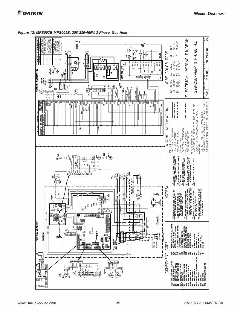
WIrIng dIagraMs
www.DaikinApplied.com 35 OM 1077-1 • MAVERICK I
WIrIng dIagraMs
Figure 12: MPS003B-MPS005B, 208-230/460V, 3-Phase, Gas Heat
DD
C
Con
trolle
r

OM 1077-1 • MAVERICK I 36 www.DaikinApplied.com
WIrIng dIagraMs
Figure 13: MPS003B-MPS005B, 575V, 3-Phase, Gas Heat
DDCController

WIrIng dIagraMs
www.DaikinApplied.com 37 OM 1077-1 • MAVERICK I
Figure 14: MPS006B-MPS007B, 208-230/460V, 3-Phase, Gas Heat
DDC Controller

OM 1077-1 • MAVERICK I 38 www.DaikinApplied.com
WIrIng dIagraMs
Figure 15: MPS006B-MPS007B, 575V, 3-Phase, Gas Heat
DDC Controller

WIrIng dIagraMs
www.DaikinApplied.com 39 OM 1077-1 • MAVERICK I
Figure 16: MPS008B-MPS012B, 208-230/460V, 3-Phase, Gas Heat
DDC Controller

OM 1077-1 • MAVERICK I 40 www.DaikinApplied.com
WIrIng dIagraMs
Figure 17: MPS008B-MPS012B, 575, 3-Phase, Gas Heat
DDC Controller

WIrIng dIagraMs
www.DaikinApplied.com 41 OM 1077-1 • MAVERICK I
Figure 18: MPS015B-MPS025B, 208-230/460V, 3-Phase, Gas Heat
DDC Controller

OM 1077-1 • MAVERICK I 42 www.DaikinApplied.com
WIrIng dIagraMs
Figure 19: MPS015B-MPS025B, 575V, 3-Phase, Gas Heat
DDC Controller

WIrIng dIagraMs
www.DaikinApplied.com 43 OM 1077-1 • MAVERICK I
Figure 20: MPS003B-MPS005B, 208-230/460V, 3-Phase, Cooling Only
DDC
Controller

OM 1077-1 • MAVERICK I 44 www.DaikinApplied.com
WIrIng dIagraMs
Figure 21: MPS006B-MPS007B, 208-230/460/575V, 3-Phase, Cooling Only
DDC Controller

WIrIng dIagraMs
www.DaikinApplied.com 45 OM 1077-1 • MAVERICK I
Figure 22: MPS008B-MPS012B, 208-230/460/575V, 3-Phase, Cooling Only
DDC Controller

OM 1077-1 • MAVERICK I 46 www.DaikinApplied.com
WIrIng dIagraMs
Figure 23: MPS015B-MPS025B, 208-230/460/575V, 3-Phase, Cooling Only
DDC Controller

daTa
www.DaikinApplied.com 47 OM 1077-1 • MAVERICK I
daTa
Table 18: Sensor Temperature vs. Resistance
TEMP °F R (OHMS) TEMP °F R (OHMS) TEMP °F R (OHMS) TEMP °F R (OHMS)
1.4 81,662 77.0 10,000 150.8 2,011 224.6 561
3.2 77,162 78.8 9,571 152.6 1,943 226.4 546
5.0 72,940 80.6 9,164 154.4 1,876 228.2 531
6.8 68,957 82.4 8,776 156.2 1,813 230.0 517
8.6 65,219 84.2 8,407 158.0 1,752 231.8 503
10.4 61,711 86.0 8,056 159.8 1,693 233.6 489
12.2 58,415 87.8 7,720 161.6 1,637 235.4 476
14.0 55,319 89.6 7,401 163.4 1,582 237.2 463
15.8 52,392 91.4 7,096 165.2 1,530 239.0 450
17.6 49,640 93.2 6,806 167.0 1,480 240.8 437
19.4 47,052 95.0 6,530 168.8 1,431 242.6 425
21.2 44,617 96.8 6,266 170.6 1,385 244.4 413
23.0 42,324 98.6 6,014 172.4 1,340 246.2 401
24.8 40,153 100.0 5,803 174.2 1,297 248.0 390
26.6 38,109 100.4 5,774 176.0 1,255 249.8 379
28.4 36,182 102.2 5,546 177.8 1,215 251.6 369
30.2 34,367 104.0 5,327 179.6 1,177 253.4 359
32.0 32,654 105.8 5,117 181.4 1,140 255.2 349
33.8 31,030 107.6 4,918 183.2 1,104 257.0 340
35.6 29,498 109.4 4,727 185.0 1,070 258.8 332
37.4 28,052 111.2 4,544 186.8 1,037 260.6 323
39.2 26,686 113.0 4,370 188.6 1,005 262.4 315
41.0 25,396 114.8 4,203 190.4 974 264.2 305
42.8 24,171 116.6 4,042 192.2 944 266.0 300
44.6 23,013 118.4 3,889 194.0 915 267.8 293
46.4 21,918 120.2 3,743 195.8 889 269.6 285
48.2 20,883 122.0 3,603 197.6 861 271.4 278
50.0 19,903 123.8 3,469 199.4 836 273.2 272
51.8 18,972 125.6 3,340 201.2 811 275.0 265
53.6 18,090 127.4 3,217 203.0 787 276.8 259
55.4 17,255 129.2 3,099 204.8 764 278.6 253
57.2 16,464 131.0 2,986 206.6 742 280.4 247
59.0 15,714 132.8 2,878 208.4 721 282.2 241
60.8 15,000 134.6 2,774 210.2 700 284.0 235
62.6 14,323 136.4 2,675 212.0 680 285.8 230
64.4 13,681 138.2 2,579 213.8 661 287.6 224
66.2 13,071 140.0 2,488 215.6 643 289.4 219
68.0 12,493 141.8 2,400 217.4 626 291.2 214
69.8 11,942 143.6 2,315 219.2 609 293.0 209
71.6 11,418 145.4 2,235 219.9 595 294.8 204
73.4 10,921 147.2 2,157 221.0 592 296.6 199
75.2 10,449 149.0 2,083 222.8 576 298.4 194

OM 1077-1 (07/16) ©2016 Daikin Applied | (800) 432–1342 | www.DaikinApplied.com
Daikin Applied Training and DevelopmentNow that you have made an investment in modern, efficient Daikin equipment, its care should be a high priority. For training information on all Daikin HVAC products, please visit us at www.DaikinApplied.com and click on Training, or call 540-248-9646 and ask for the Training Department.
Warranty
All Daikin equipment is sold pursuant to its standard terms and conditions of sale, including Limited Product Warranty. Consult your local Daikin Applied representative for warranty details. To find your local Daikin Applied representative, go to www.DaikinApplied.com.
Aftermarket Services
To find your local parts office, visit www.DaikinApplied.com or call 800-37PARTS (800-377-2787). To find your local service office, visit www.DaikinApplied.com or call 800-432-1342.
This document contains the most current product information as of this printing. For the most up-to-date product information, please go to www.DaikinApplied.com.
Products manufactured in an ISO Certified Facility.


![Reversing and Malware Analysis Training Articles [2012] . cracking/Reversing... · Reversing and Malware Analysis Training Articles ... Step 1: Start with what you ... Reversing and](https://img.pdfslide.us/doc/110x75/5ab905fd7f8b9ac10d8db0ab/reversing-and-malware-analysis-training-articles-2012-crackingreversingreversing.jpg)