Embed Size (px)
Citation preview

802.11g Internet Camerawith Pan, Tilt, & Digital Zoom
Manual
Building Networks for People
Version 1.00
DCS-5300G
(07/16/04)
2
ContentsContents of Package .......................................................................................3Introduction ......................................................................................................4Features and Benefits .....................................................................................4Connections ....................................................................................................6Hardware Installation .......................................................................................9Software Installation ......................................................................................10Installation Wizard Screen ............................................................................15Enabling UPnP for Windows XP/Me..............................................................18Installing IP surveillance Software .................................................................22Testing the DCS-5300G ................................................................................ 26Security .........................................................................................................27Using and Configuring the DCS-5300G with a NAT Router ..........................28Using the DCS-5300G with an Internet Browser ...........................................34Record Snapshots to your FTP server with Motion Detection.......................64Using IP surveillance Software ......................................................................68 Installing IP surveillance Software .....................................................68 Launcher ...........................................................................................73 Monitor Program ................................................................................ 76 Scheduling ....................................................................................... 101 Playback Program ........................................................................... 109Appendix ...................................................................................................... 124
Frequently Asked Questions ............................................................ 124How to PING Your IP Address .......................................................... 127Reset and Restore .......................................................................... 128I/O Connector .................................................................................. 129Adjusting the Camera Focus ........................................................... 133Technical Specifications .................................................................. 134
Contacting Technical Support ..................................................................... 136Time Zone Table .......................................................................................... 137Warranty and Registration ........................................................................... 139
3
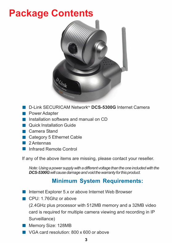
D-Link SECURICAM Network DCS-5300G Internet CameraPower AdapterInstallation software and manual on CDQuick Installation GuideCamera StandCategory 5 Ethernet Cable2 AntennasInfrared Remote Control
Note: Using a power supply with a different voltage than the one included with theDCS-5300G will cause damage and void the warranty for this product.
Minimum System Requirements:
Internet Explorer 5.x or above Internet Web BrowserCPU: 1.76Ghz or above(2.4GHz plus processor with 512MB memory and a 32MB videocard is required for multiple camera viewing and recording in IPSurveillance)Memory Size: 128MBVGA card resolution: 800 x 600 or above
Package Contents
If any of the above items are missing, please contact your reseller.
TM
4
IntroductionThe D-Link SECURICAM Network DCS-5300G Wireless Internet Camera isa powerful surveillance system that connects wirelessly to your 802.11g network.The DCS-5300G features 802.11g and connects with a maximum wirelesssignal rate of up to 54Mbps (Megabits per second). The DCS-5300G is thelatest product added to the D-Link Internet camera line. The DCS-5300G canbe used with any wired or wireless router to connect to a wireless 802.11gEthernet or Fast Ethernet Network. The camera features a motorized pan andtilt function found on more expensive cameras. This function allows the viewingarea of the camera to extend 270o side-to-side and 90o up and down. You canalso zoom in on all the action with the DCS-5300G’s 4x digital zoom feature.The DCS-5300G gives you the ability to monitor your home/office using anInternet browser from any where in the world!
Motorized Pan/Tilt and Digital ZoomThe DCS-5300G has a pan and tilt function that can expand your viewing areato cover a wide 270o angle side-to-side and a 90o angle up and down. Auto panmode enables the camera to move 270o horizontally and the patrol mode cyclesthrough up to 20 preset positions. The pan/tilt speed can be adjusted to yourpreference. You can control camera movement with a PC from any location, orlocally using the included infrared remote control. The DCS-5300G also features4x digital zoom for closer viewing.
CCD SensorThe DCS-5300G comes standard with a high quality CCD sensor that is superiorto a CMOS type sensor. The fixed focus glass lens will facilitate the use of theDCS-5300G providing crystal clear and sharp images. You can view up to30 frames per second of live motion video with 380 TV lines of resolution.
1
Features and BenefitsThe D-Link SECURICAM Network DCS-5300G Wireless Internet Cameraensures compatibility with your computer and operating system by utilizing aWeb management interface, accessible by using Internet Explorer 5.x and above.You can remotely gain access to the camera, view live video, listen to soundspicked up by the built-in microphone and make changes to the camera settingsfrom your web browser.
2
Maximum wireless signal rate derived from IEEE Standard 802.11g specifications. Actual data throughputwill vary. Network conditions and environmental factors lower actual data throughput rate. Actual frame rate will vary due to network traffic, compression rate, frame rate, and lighting.
1
TM
2
TM
5
Features & Benefits (continued)
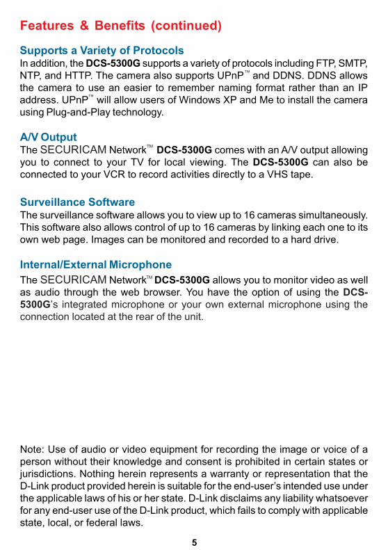
A/V OutputThe SECURICAM Network DCS-5300G comes with an A/V output allowingyou to connect to your TV for local viewing. The DCS-5300G can also beconnected to your VCR to record activities directly to a VHS tape.
Surveillance SoftwareThe surveillance software allows you to view up to 16 cameras simultaneously.This software also allows control of up to 16 cameras by linking each one to itsown web page. Images can be monitored and recorded to a hard drive.
Internal/External MicrophoneThe SECURICAM Network DCS-5300G allows you to monitor video as wellas audio through the web browser. You have the option of using the DCS-5300G’s integrated microphone or your own external microphone using theconnection located at the rear of the unit.
Note: Use of audio or video equipment for recording the image or voice of aperson without their knowledge and consent is prohibited in certain states orjurisdictions. Nothing herein represents a warranty or representation that theD-Link product provided herein is suitable for the end-user’s intended use underthe applicable laws of his or her state. D-Link disclaims any liability whatsoeverfor any end-user use of the D-Link product, which fails to comply with applicablestate, local, or federal laws.
Supports a Variety of ProtocolsIn addition, the DCS-5300G supports a variety of protocols including FTP, SMTP,NTP, and HTTP. The camera also supports UPnP and DDNS. DDNS allowsthe camera to use an easier to remember naming format rather than an IPaddress. UPnP will allow users of Windows XP and Me to install the camerausing Plug-and-Play technology.
TM
TM
TM
TM
6
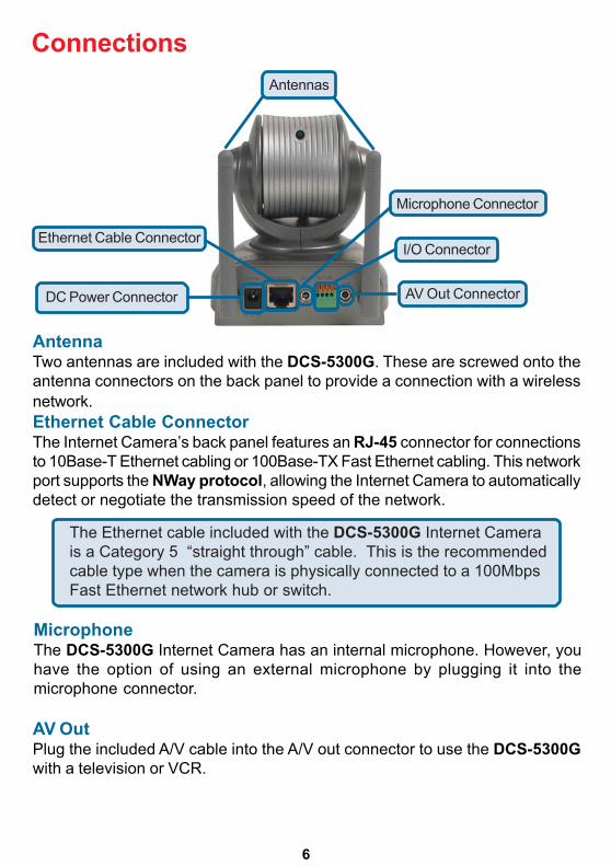
Connections
AntennaTwo antennas are included with the DCS-5300G. These are screwed onto theantenna connectors on the back panel to provide a connection with a wirelessnetwork.Ethernet Cable ConnectorThe Internet Camera’s back panel features an RJ-45 connector for connectionsto 10Base-T Ethernet cabling or 100Base-TX Fast Ethernet cabling. This networkport supports the NWay protocol, allowing the Internet Camera to automaticallydetect or negotiate the transmission speed of the network.
The Ethernet cable included with the DCS-5300G Internet Camerais a Category 5 “straight through” cable. This is the recommendedcable type when the camera is physically connected to a 100MbpsFast Ethernet network hub or switch.
Antennas
Ethernet Cable Connector
DC Power Connector
I/O Connector
Microphone Connector
AV Out Connector
MicrophoneThe DCS-5300G Internet Camera has an internal microphone. However, youhave the option of using an external microphone by plugging it into themicrophone connector.
AV OutPlug the included A/V cable into the A/V out connector to use the DCS-5300Gwith a television or VCR.
7
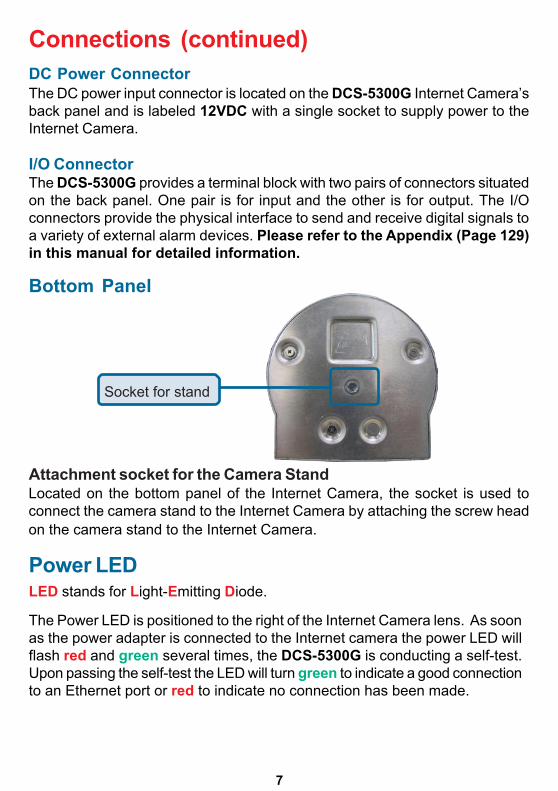
DC Power ConnectorThe DC power input connector is located on the DCS-5300G Internet Camera’sback panel and is labeled 12VDC with a single socket to supply power to theInternet Camera.
I/O ConnectorThe DCS-5300G provides a terminal block with two pairs of connectors situatedon the back panel. One pair is for input and the other is for output. The I/Oconnectors provide the physical interface to send and receive digital signals toa variety of external alarm devices. Please refer to the Appendix (Page 129)in this manual for detailed information.
Connections (continued)
Located on the bottom panel of the Internet Camera, the socket is used toconnect the camera stand to the Internet Camera by attaching the screw headon the camera stand to the Internet Camera.
Bottom Panel
Socket for stand
Power LEDLED stands for Light-Emitting Diode.
The Power LED is positioned to the right of the Internet Camera lens. As soonas the power adapter is connected to the Internet camera the power LED willflash red and green several times, the DCS-5300G is conducting a self-test.Upon passing the self-test the LED will turn green to indicate a good connectionto an Ethernet port or red to indicate no connection has been made.
Attachment socket for the Camera Stand
8
Connections (continued)
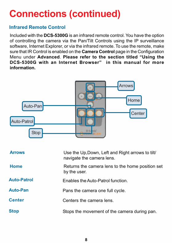
Included with the DCS-5300G is an infrared remote control. You have the optionof controlling the camera via the Pan/Tilt Controls using the IP surveillancesoftware, Internet Explorer, or via the infrared remote. To use the remote, makesure that IR Control is enabled on the Camera Control page in the ConfigurationMenu under Advanced. Please refer to the section titled “Using theDCS-5300G with an Internet Browser” in this manual for moreinformation.
Infrared Remote Control
Stop
Auto-Patrol
Auto-PanCenter
Home
Arrows
Arrows Use the Up,Down, Left and Right arrows to tilt/navigate the camera lens.
Home Returns the camera lens to the home position setby the user.
Auto-Patrol Enables the Auto-Patrol function.
Auto-Pan
Center Centers the camera lens.
Pans the camera one full cycle.
Stop Stops the movement of the camera during pan.
9
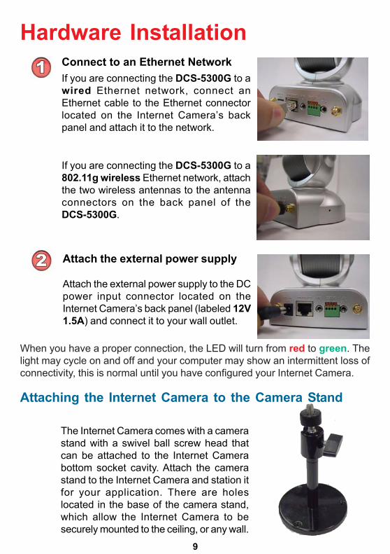
Hardware InstallationConnect to an Ethernet NetworkIf you are connecting the DCS-5300G to awired Ethernet network, connect anEthernet cable to the Ethernet connectorlocated on the Internet Camera’s backpanel and attach it to the network.
If you are connecting the DCS-5300G to a802.11g wireless Ethernet network, attachthe two wireless antennas to the antennaconnectors on the back panel of theDCS-5300G.
Attach the external power supply
Attach the external power supply to the DCpower input connector located on theInternet Camera’s back panel (labeled 12V1.5A) and connect it to your wall outlet.
The Internet Camera comes with a camerastand with a swivel ball screw head thatcan be attached to the Internet Camerabottom socket cavity. Attach the camerastand to the Internet Camera and station itfor your application. There are holeslocated in the base of the camera stand,which allow the Internet Camera to besecurely mounted to the ceiling, or any wall.
Attaching the Internet Camera to the Camera Stand
When you have a proper connection, the LED will turn from red to green. Thelight may cycle on and off and your computer may show an intermittent loss ofconnectivity, this is normal until you have configured your Internet Camera.
10
Software InstallationAfter you have successfully completed the hardware installation of theDCS-5300G Internet Camera, it is necessary to install software to configureand operate the camera. The first step is to install the Installation Wizard fromthe CD. Installation Wizard will allow you to configure the Internet Camera toyour network.
After the Installation Wizard software program is completed, you will have anoperating and controllable Internet Camera. From your Internet Explorer Webbrowser you will be able to access the video and sound from the Internet camera.The camera has a built-in Web server. This Web server will allow the camera toaccess the Internet without being attached to a computer and permits users toview the video and audio remotely.
However, it is necessary to install the IP surveillance software from the enclosedCD to create a truly powerful monitoring and surveillance system. The followingsection will detail the installation of the Installation Wizard and the IPsurveillance software.
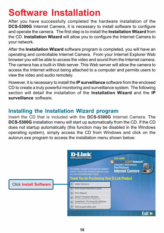
Installing the Installation Wizard programInsert the CD that is included with the DCS-5300G Internet Camera. TheDCS-5300G installation menu will start up automatically from the CD. If the CDdoes not startup automatically (this function may be disabled in the Windowsoperating system), simply access the CD from Windows and click on theautorun.exe program to access the installation menu shown below:
Click Install Software
11
Software Installation (continued)
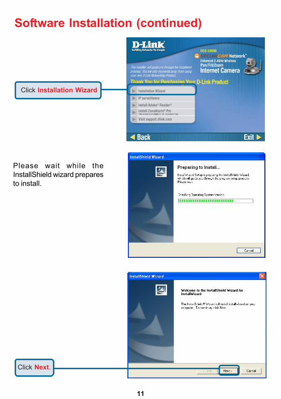
Please wait while theInstallShield wizard preparesto install.
Click Next.
Click Installation Wizard
12
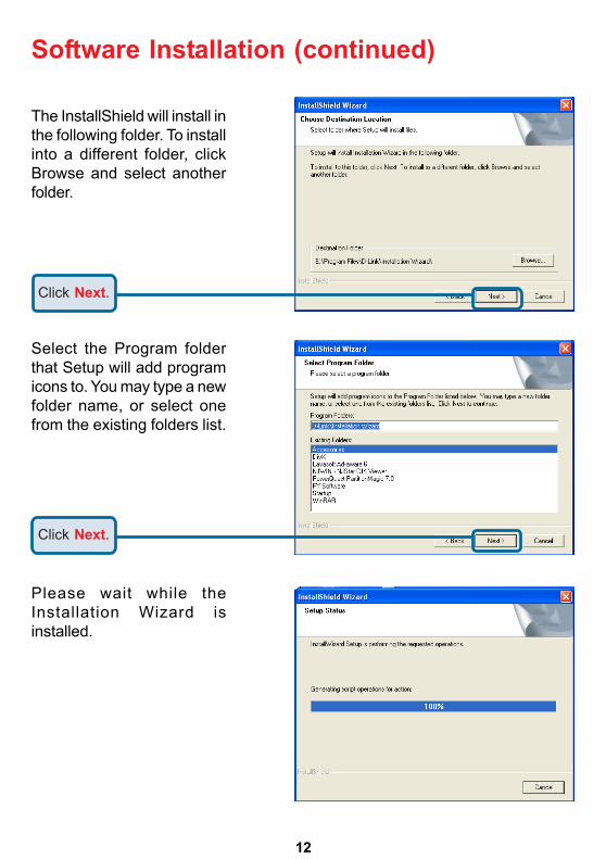
Select the Program folderthat Setup will add programicons to. You may type a newfolder name, or select onefrom the existing folders list.
Click Next.
Please wait while theInstallation Wizard isinstalled.
Software Installation (continued)
The InstallShield will install inthe following folder. To installinto a different folder, clickBrowse and select anotherfolder.
Click Next.
13
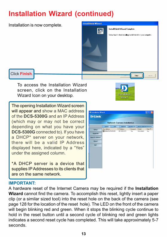
Installation Wizard (continued)
To access the Installation Wizardscreen, click on the InstallationWizard Icon on your desktop.
IMPORTANT:A hardware reset of the Internet Camera may be required if the InstallationWizard cannot find the camera. To accomplish this reset, lightly insert a paperclip (or a similar sized tool) into the reset hole on the back of the camera (seepage 128 for the location of the reset hole). The LED on the front of the camerawill begin blinking red and green. When it stops the blinking cycle continue tohold in the reset button until a second cycle of blinking red and green lightsindicates a second reset cycle has completed. This will take approximately 5-7seconds.
The opening Installation Wizard screenwill appear and show a MAC addressof the DCS-5300G and an IP Address(which may or may not be correctdepending on what you have yourDCS-5300G connected to). If you havea DHCP* server on your network,there will be a valid IP Addressdisplayed here, indicated by a “Yes”under the assigned column.
*A DHCP server is a device thatsupplies IP Addresses to its clients thatare on the same network.
Installation is now complete.
Click Finish.
DCS-5300G
14
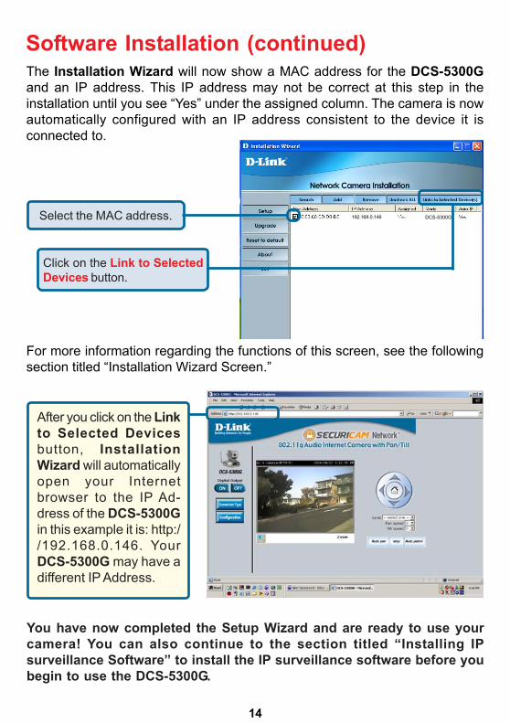
Software Installation (continued)
You have now completed the Setup Wizard and are ready to use yourcamera! You can also continue to the section titled “Installing IPsurveillance Software” to install the IP surveillance software before youbegin to use the DCS-5300G.
The Installation Wizard will now show a MAC address for the DCS-5300Gand an IP address. This IP address may not be correct at this step in theinstallation until you see “Yes” under the assigned column. The camera is nowautomatically configured with an IP address consistent to the device it isconnected to.
After you click on the Linkto Selected Devicesbutton, InstallationWizard will automaticallyopen your Internetbrowser to the IP Ad-dress of the DCS-5300Gin this example it is: http://192.168.0.146. YourDCS-5300G may have adifferent IP Address.
Click on the Link to SelectedDevices button.
Select the MAC address.
For more information regarding the functions of this screen, see the followingsection titled “Installation Wizard Screen.”
DCS-5300G192.168.0.146
15
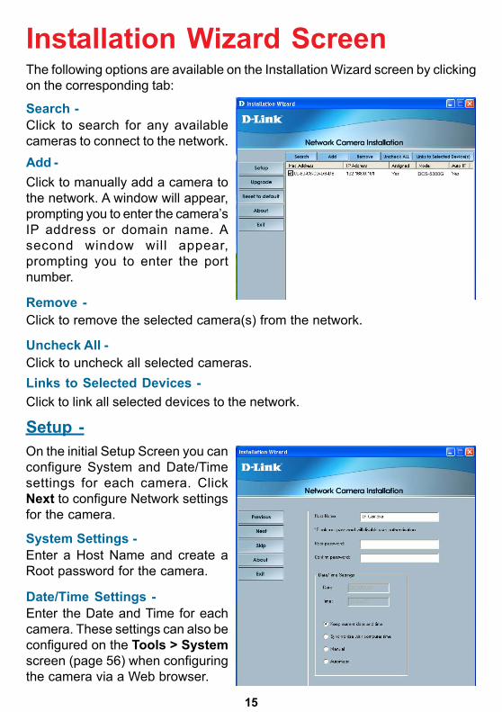
Installation Wizard ScreenThe following options are available on the Installation Wizard screen by clickingon the corresponding tab:
Search -Click to search for any availablecameras to connect to the network.Add -Click to manually add a camera tothe network. A window will appear,prompting you to enter the camera’sIP address or domain name. Asecond window will appear,prompting you to enter the portnumber.
Remove -Click to remove the selected camera(s) from the network.
Uncheck All -Click to uncheck all selected cameras.Links to Selected Devices -Click to link all selected devices to the network.
Setup -On the initial Setup Screen you canconfigure System and Date/Timesettings for each camera. ClickNext to configure Network settingsfor the camera.
System Settings -Enter a Host Name and create aRoot password for the camera.
Date/Time Settings -Enter the Date and Time for eachcamera. These settings can also beconfigured on the Tools > Systemscreen (page 56) when configuringthe camera via a Web browser.
DCS-5300G
16
Installation Wizard Screen (continued)
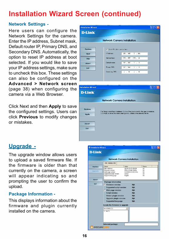
Upgrade -
Network Settings -Here users can configure theNetwork Settings for the camera.Enter the IP address, Subnet mask,Default router IP, Primary DNS, andSecondary DNS. Automatically, theoption to reset IP address at bootselected. If you would like to saveyour IP address settings, make sureto uncheck this box. These settingscan also be configured on theAdvanced > Network screen(page 38) when configuring thecamera via a Web Browser.
Click Next and then Apply to savethe configured settings. Users canclick Previous to modify changesor mistakes.
The upgrade window allows usersto upload a saved firmware file. Ifthe firmware is older than thatcurrently on the camera, a screenwill appear indicating so andprompting the user to confirm theupload.
Package Information -This displays information about thefirmware and plugin currentlyinstalled on the camera.
DCS5300G-DLINK-0100a
17
Installation Wizard Screen (continued)
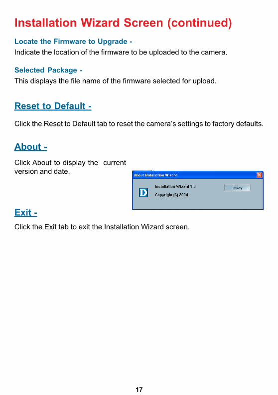
Reset to Default -
About -
Exit -Click the Exit tab to exit the Installation Wizard screen.
Click About to display the currentversion and date.
Click the Reset to Default tab to reset the camera’s settings to factory defaults.
Locate the Firmware to Upgrade -Indicate the location of the firmware to be uploaded to the camera.
Selected Package -This displays the file name of the firmware selected for upload.
18
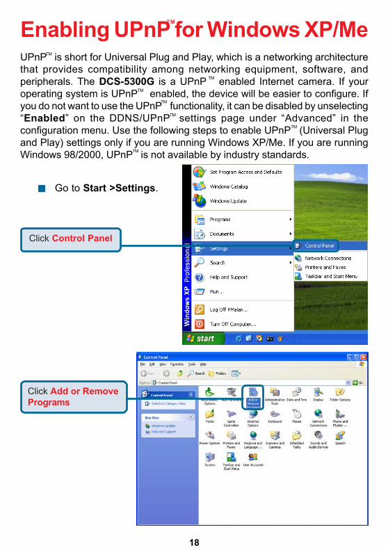
Enabling UPnP for Windows XP/MeUPnP is short for Universal Plug and Play, which is a networking architecturethat provides compatibility among networking equipment, software, andperipherals. The DCS-5300G is a UPnP enabled Internet camera. If youroperating system is UPnP enabled, the device will be easier to configure. Ifyou do not want to use the UPnP functionality, it can be disabled by unselecting“Enabled” on the DDNS/UPnP settings page under “Advanced” in theconfiguration menu. Use the following steps to enable UPnP (Universal Plugand Play) settings only if you are running Windows XP/Me. If you are runningWindows 98/2000, UPnP is not available by industry standards.
Click Control Panel
Go to Start >Settings.
Click Add or RemovePrograms
TM
TM
TM
TM
TM
TM
TM
TM
19
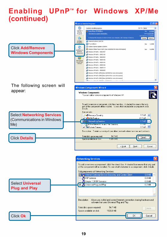
Click Add/RemoveWindows Components
The following screen willappear:
Select Networking Services(Communications in WindowsMe)
Click Details
Select UniversalPlug and Play
Click Ok
Enabling UPnP for Windows XP/Me(continued)
TM
20
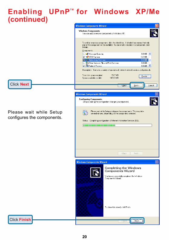
Please wait while Setupconfigures the components.
Click Next
Click Finish
Enabling UPnP for Windows XP/Me(continued)
TM
21
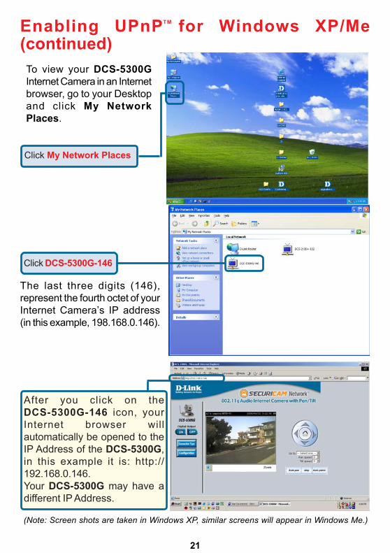
Click My Network Places
To view your DCS-5300GInternet Camera in an Internetbrowser, go to your Desktopand click My NetworkPlaces.
Click DCS-5300G-146
The last three digits (146),represent the fourth octet of yourInternet Camera’s IP address(in this example, 198.168.0.146).
(Note: Screen shots are taken in Windows XP, similar screens will appear in Windows Me.)
Enabling UPnP for Windows XP/Me(continued)
After you click on theDCS-5300G-146 icon, yourInternet browser willautomatically be opened to theIP Address of the DCS-5300G,in this example it is: http://192.168.0.146.Your DCS-5300G may have adifferent IP Address.
TM
22
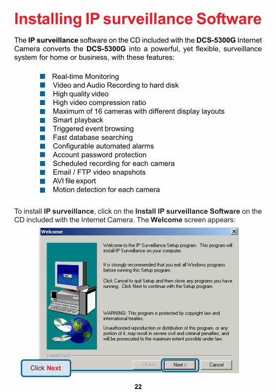
Click Next
Real-time MonitoringVideo and Audio Recording to hard diskHigh quality videoHigh video compression ratioMaximum of 16 cameras with different display layoutsSmart playbackTriggered event browsingFast database searchingConfigurable automated alarmsAccount password protectionScheduled recording for each cameraEmail / FTP video snapshotsAVI file exportMotion detection for each camera
The IP surveillance software on the CD included with the DCS-5300G InternetCamera converts the DCS-5300G into a powerful, yet flexible, surveillancesystem for home or business, with these features:
Installing IP surveillance Software
To install IP surveillance, click on the Install IP surveillance Software on theCD included with the Internet Camera. The Welcome screen appears:
23
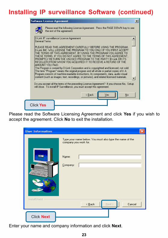
Please read the Software Licensing Agreement and click Yes if you wish toaccept the agreement. Click No to exit the installation.
Enter your name and company information and click Next.
Click Next
Installing IP surveillance Software (continued)
Click Yes
24
Installing IP surveillance Software (continued)
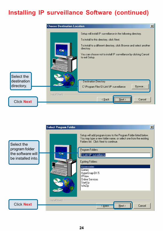
Click Next
Click Next
Select thedestinationdirectory.
Select theprogram folderthe software willbe installed into.
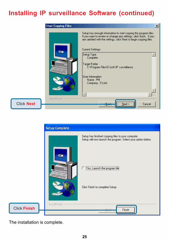
25
The installation is complete.
Click Finish
Installing IP surveillance Software (continued)
Click Next
26
Testing the DCS-5300G InternetCamera
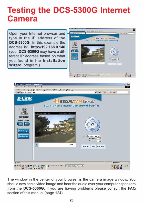
The window in the center of your browser is the camera image window. Youshould now see a video image and hear the audio over your computer speakersfrom the DCS-5300G. If you are having problems please consult the FAQsection of this manual (page 124).
Open your Internet browser andtype in the IP address of theDCS-5300G. In this example theaddress is: http://192.168.0.146(your DCS-5300G may have a dif-ferent IP address based on whatyou found in the InstallationWizard program.)
27
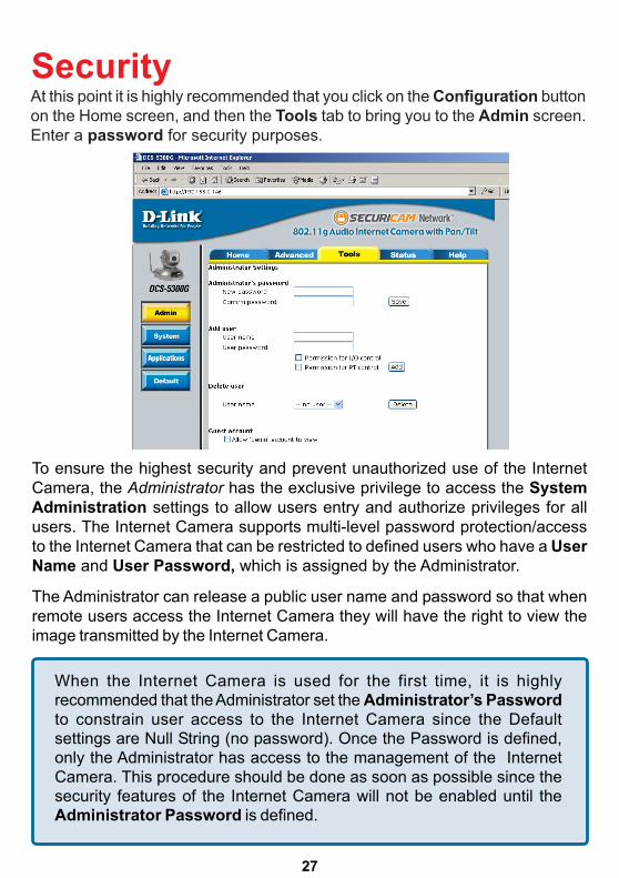
When the Internet Camera is used for the first time, it is highlyrecommended that the Administrator set the Administrator’s Passwordto constrain user access to the Internet Camera since the Defaultsettings are Null String (no password). Once the Password is defined,only the Administrator has access to the management of the InternetCamera. This procedure should be done as soon as possible since thesecurity features of the Internet Camera will not be enabled until theAdministrator Password is defined.
To ensure the highest security and prevent unauthorized use of the InternetCamera, the Administrator has the exclusive privilege to access the SystemAdministration settings to allow users entry and authorize privileges for allusers. The Internet Camera supports multi-level password protection/accessto the Internet Camera that can be restricted to defined users who have a UserName and User Password, which is assigned by the Administrator.
The Administrator can release a public user name and password so that whenremote users access the Internet Camera they will have the right to view theimage transmitted by the Internet Camera.
At this point it is highly recommended that you click on the Configuration buttonon the Home screen, and then the Tools tab to bring you to the Admin screen.Enter a password for security purposes.
Security
28
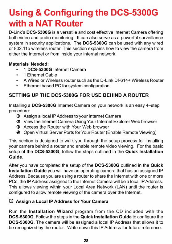
Using & Configuring the DCS-5300Gwith a NAT RouterD-Link’s DCS-5300G is a versatile and cost effective Internet Camera offeringboth video and audio monitoring. It can also serve as a powerful surveillancesystem in security applications. The DCS-5300G can be used with any wiredor 802.11b wireless router. This section explains how to view the camera fromeither the Internet or from inside your internal network.
Materials Needed:• 1 DCS-5300G Internet Camera• 1 Ethernet Cable• A Wired or Wireless router such as the D-Link DI-614+ Wireless Router• Ethernet based PC for system configuration
SETTING UP THE DCS-5300G FOR USE BEHIND A ROUTER
Installing a DCS-5300G Internet Camera on your network is an easy 4–stepprocedure:
Assign a local IP Address to your Internet CameraView the Internet Camera Using Your Internet Explorer Web browserAccess the Router with Your Web browserOpen Virtual Server Ports for Your Router (Enable Remote Viewing)
This section is designed to walk you through the setup process for installingyour camera behind a router and enable remote video viewing. For the basicsetup of the DCS-5300G, follow the steps outlined in the Quick InstallationGuide.
After you have completed the setup of the DCS-5300G outlined in the QuickInstallation Guide you will have an operating camera that has an assigned IPAddress. Because you are using a router to share the Internet with one or morePCs, the IP Address assigned to the Internet Camera will be a local IP Address.This allows viewing within your Local Area Network (LAN) until the router isconfigured to allow remote viewing of the camera over the Internet.
Run the Installation Wizard program from the CD included with theDCS-5300G. Follow the steps in the Quick Installation Guide to configure theDCS-5300G. The camera will be assigned a local IP Address that allows it tobe recognized by the router. Write down this IP Address for future reference.
Assign a Local IP Address for Your Camera
29
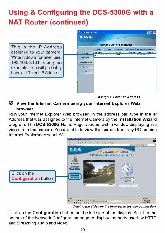
Using & Configuring the DCS-5300G with aNAT Router (continued)
Assign a Local IP Address
View the Internet Camera using your Internet Explorer Web browser
Viewing the Video on the browser to test the connection
Click on the Configuration button on the left side of the display. Scroll to thebottom of the Network Configuration page to display the ports used by HTTPand Streaming audio and video.
This is the IP Addressassigned to your camera.Write it down for later use.192.168.0.101 is only anexample. You will probablyhave a different IP Address.
Run your Internet Explorer Web browser. In the address bar, type in the IPAddress that was assigned to the Internet Camera by the Installation Wizardprogram. The DCS-5300G Home Page appears with a window displaying livevideo from the camera. You are able to view this screen from any PC runningInternet Explorer on your LAN.
Click on theConfiguration button.
DCS-5300G
30
Using & Configuring the DCS-5300G with aNAT Router (continued)
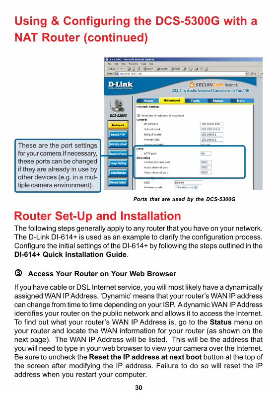
Router Set-Up and InstallationThe following steps generally apply to any router that you have on your network.The D-Link DI-614+ is used as an example to clarify the configuration process.Configure the initial settings of the DI-614+ by following the steps outlined in theDI-614+ Quick Installation Guide.
Access Your Router on Your Web Browser
If you have cable or DSL Internet service, you will most likely have a dynamicallyassigned WAN IP Address. ‘Dynamic’ means that your router’s WAN IP addresscan change from time to time depending on your ISP. A dynamic WAN IP Addressidentifies your router on the public network and allows it to access the Internet.To find out what your router’s WAN IP Address is, go to the Status menu onyour router and locate the WAN information for your router (as shown on thenext page). The WAN IP Address will be listed. This will be the address thatyou will need to type in your web browser to view your camera over the Internet.Be sure to uncheck the Reset the IP address at next boot button at the top ofthe screen after modifying the IP address. Failure to do so will reset the IPaddress when you restart your computer.
These are the port settingsfor your camera.If necessary,these ports can be changedif they are already in use byother devices (e.g. in a mul-tiple camera environment).
Ports that are used by the DCS-5300G
31
http://192.168.0.1
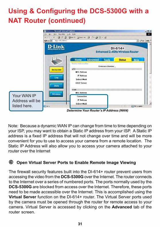
Determine Your Router’s IP Address (WAN)
Note: Because a dynamic WAN IP can change from time to time depending onyour ISP, you may want to obtain a Static IP address from your ISP. A Static IPaddress is a fixed IP address that will not change over time and will be moreconvenient for you to use to access your camera from a remote location. TheStatic IP Address will also allow you to access your camera attached to yourrouter over the Internet
Open Virtual Server Ports to Enable Remote Image Viewing
Your WAN IPAddress will belisted here.
Using & Configuring the DCS-5300G with aNAT Router (continued)
The firewall security features built into the DI-614+ router prevent users fromaccessing the video from the DCS-5300G over the Internet. The router connectsto the Internet over a series of numbered ports. The ports normally used by theDCS-5300G are blocked from access over the Internet. Therefore, these portsneed to be made accessible over the Internet. This is accomplished using theVirtual Server function on the DI-614+ router. The Virtual Server ports usedby the camera must be opened through the router for remote access to yourcamera. Virtual Server is accessed by clicking on the Advanced tab of therouter screen.
32
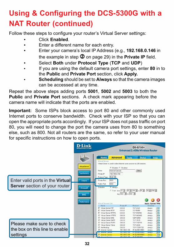
Important: Some ISPs block access to port 80 and other commonly usedInternet ports to conserve bandwidth. Check with your ISP so that you canopen the appropriate ports accordingly. If your ISP does not pass traffic on port80, you will need to change the port the camera uses from 80 to somethingelse, such as 800. Not all routers are the same, so refer to your user manualfor specific instructions on how to open ports.
Using & Configuring the DCS-5300G with aNAT Router (continued)
Enter valid ports in the VirtualServer section of your router
192.168.0.102
Follow these steps to configure your router’s Virtual Server settings:
Repeat the above steps adding ports 5001, 5002 and 5003 to both thePublic and Private Port sections. A check mark appearing before thecamera name will indicate that the ports are enabled.
• Click Enabled.• Enter a different name for each entry.• Enter your camera’s local IP Address (e.g., 192.168.0.146 in
the example in step on page 29) in the Private IP field.• Select Both under Protocol Type (TCP and UDP)• If you are using the default camera port settings, enter 80 in to
the Public and Private Port section, click Apply.• Scheduling should be set to Always so that the camera images
can be accessed at any time.
Please make sure to checkthe box on this line to enablesettings
33
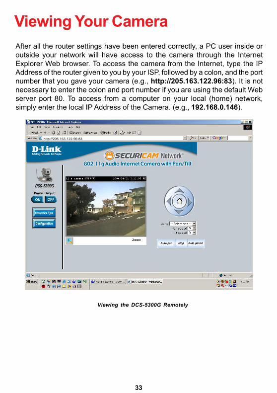
Viewing Your CameraAfter all the router settings have been entered correctly, a PC user inside oroutside your network will have access to the camera through the InternetExplorer Web browser. To access the camera from the Internet, type the IPAddress of the router given to you by your ISP, followed by a colon, and the portnumber that you gave your camera (e.g., http://205.163.122.96:83). It is notnecessary to enter the colon and port number if you are using the default Webserver port 80. To access from a computer on your local (home) network,simply enter the local IP Address of the Camera. (e.g., 192.168.0.146).
Viewing the DCS-5300G Remotely
http://205.163.122.96:83
34
Open your Internet Explorer Web browser and enter the IP address for yourInternet Camera.In the example, this address is 192.168.0.146. Your address may differ.
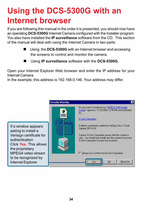
If a window appearsasking to install aVerisign certificate forauthenticationClick Yes. This allowsthe proprietaryMPEG4 video streamto be recognized byInternet Explorer.
If you are following this manual in the order it is presented, you should now havean operating DCS-5300G Internet Camera configured with the Installer program.You also have installed the IP surveillance software from the CD. This sectionof the manual will deal with using the Internet Camera in two parts:
Using the DCS-5300G with an Internet browser and accessing the screens to control and monitor the camera.
Using IP surveillance software with the DCS-5300G.
Using the DCS-5300G with anInternet browser
35
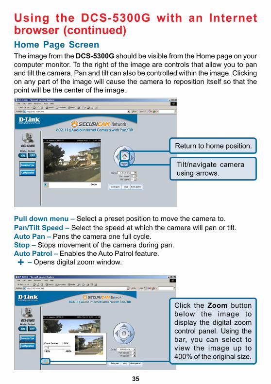
Home Page ScreenThe image from the DCS-5300G should be visible from the Home page on yourcomputer monitor. To the right of the image are controls that allow you to panand tilt the camera. Pan and tilt can also be controlled within the image. Clickingon any part of the image will cause the camera to reposition itself so that thepoint will be the center of the image.
Using the DCS-5300G with an Internetbrowser (continued)
Pull down menu – Select a preset position to move the camera to.Pan/Tilt Speed – Select the speed at which the camera will pan or tilt.Auto Pan – Pans the camera one full cycle.Stop – Stops movement of the camera during pan.Auto Patrol – Enables the Auto Patrol feature. – Opens digital zoom window.
Return to home position.
Tilt/navigate camerausing arrows.
Click the Zoom buttonbelow the image todisplay the digital zoomcontrol panel. Using thebar, you can select toview the image up to400% of the original size.
+
36
Home Page Screen (continued)
Using the DCS-5300G with an Internetbrowser (continued)
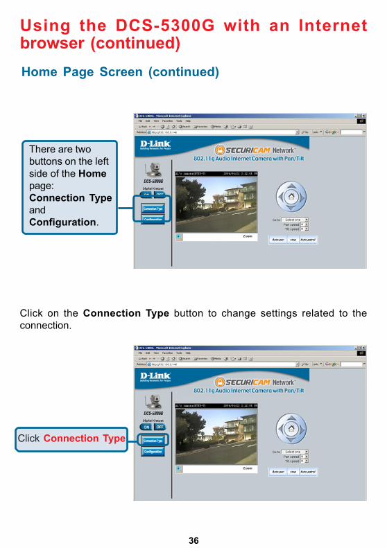
Click on the Connection Type button to change settings related to theconnection.
There are twobuttons on the leftside of the Homepage:Connection TypeandConfiguration.
Click Connection Type
37
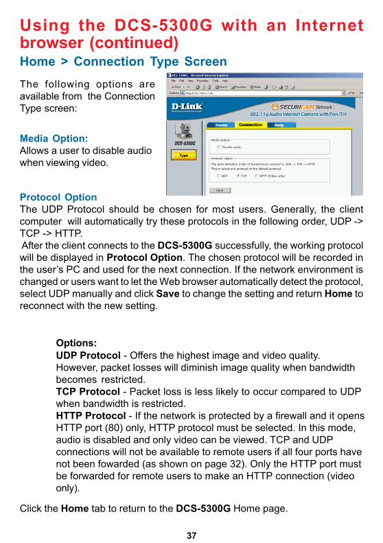
Home > Connection Type Screen
Protocol OptionThe UDP Protocol should be chosen for most users. Generally, the clientcomputer will automatically try these protocols in the following order, UDP ->TCP -> HTTP. After the client connects to the DCS-5300G successfully, the working protocolwill be displayed in Protocol Option. The chosen protocol will be recorded inthe user’s PC and used for the next connection. If the network environment ischanged or users want to let the Web browser automatically detect the protocol,select UDP manually and click Save to change the setting and return Home toreconnect with the new setting.
Media Option:Allows a user to disable audiowhen viewing video.
The following options areavailable from the ConnectionType screen:
Using the DCS-5300G with an Internetbrowser (continued)
Options:UDP Protocol - Offers the highest image and video quality.However, packet losses will diminish image quality when bandwidthbecomes restricted.TCP Protocol - Packet loss is less likely to occur compared to UDPwhen bandwidth is restricted.HTTP Protocol - If the network is protected by a firewall and it opensHTTP port (80) only, HTTP protocol must be selected. In this mode,audio is disabled and only video can be viewed. TCP and UDPconnections will not be available to remote users if all four ports havenot been fowarded (as shown on page 32). Only the HTTP port mustbe forwarded for remote users to make an HTTP connection (videoonly).
Click the Home tab to return to the DCS-5300G Home page.
38
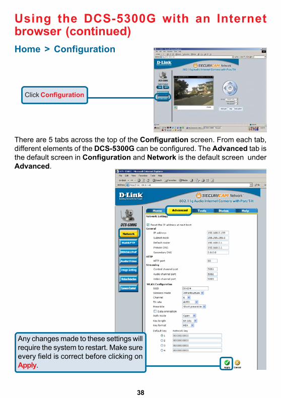
Home > Configuration
There are 5 tabs across the top of the Configuration screen. From each tab,different elements of the DCS-5300G can be configured. The Advanced tab isthe default screen in Configuration and Network is the default screen underAdvanced.
Using the DCS-5300G with an Internetbrowser (continued)
Click Configuration
Any changes made to these settings willrequire the system to restart. Make sureevery field is correct before clicking onApply.
39
Configuration > Advanced > Network
Reset IP Address at next boot
IP address - Necessary for network identification.
Subnet mask - Used to determine if the destination is in the samesubnet. The default value is “255.255.255.0.”
Once the DCS-5300G is configured, this box should be unchecked at all times.If the box has been checked and the connection is lost, run the InstallationWizard to find the camera’s IP address.
Default router - The router used to forward frames to destinationsin a different subnet. Invalid router settings maycause the failure of transmissions to a differentsubnet.
Primary DNS - Primary domain name server that translatesnames to IP addresses.
Secondary DNS - Secondary domain name server to backup theprimary one.
General Settings
Using the DCS-5300G with an Internetbrowser (continued)
Can be set to other than the default port 80. Whenthe administrator changes the HTTP port of theDCS-5300G (which has an IP address of192.168.0.100) from 80 to 8080, users must typehttp://192.168.0.100:8080 in the Web browserbar.
HTTP Port-
HTTP Settings
40
Configuration > Advanced >Network Settings (continued)
SSID - (Service Set Identifier) is a name that identifies awireless network. Access Points and wirelessclients attempting to connect to a specific WLAN(Wireless Local Area Network) must use thesame SSID. The default setting is default.
Wireless Mode- Click on the pull-down menu; select from thefollowing options:Infrastructure - connecting the WLAN using anAccess Point such as the DWL-1000AP+. (Thedefault setting.)Ad-Hoc – wireless mode used when connectingdirectly to a computer equipped with a wirelessadapter in a peer-to-peer environment.
Using the DCS-5300G with an Internetbrowser (continued)
Streaming SettingsControl channel port - Can be set to other than the default port 5001 to
correspond with the port opened by the firewall.
Audio channel port - Can be set to other than the default port 5002 tocorrespond with the port opened by the firewall.
Video channel port - Can be set to other than the default port 5003 tocorrespond with the port opened by the firewall.
WLAN Configuration Settings
Improve audio qualityin low bandwidthenvironment - In a low bandwidth network environment you can
check this option to improve audio quality bysacrificing some real-time synchronization.
41
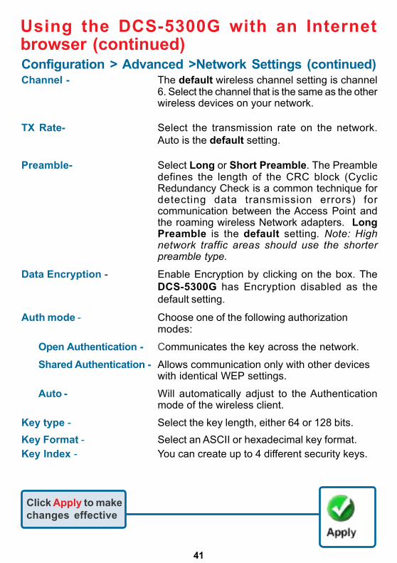
Using the DCS-5300G with an Internetbrowser (continued)Configuration > Advanced >Network Settings (continued)Channel - The default wireless channel setting is channel
6. Select the channel that is the same as the otherwireless devices on your network.
TX Rate- Select the transmission rate on the network.Auto is the default setting.
Preamble- Select Long or Short Preamble. The Preambledefines the length of the CRC block (CyclicRedundancy Check is a common technique fordetecting data transmission errors) forcommunication between the Access Point andthe roaming wireless Network adapters. LongPreamble is the default setting. Note: Highnetwork traffic areas should use the shorterpreamble type.
Data Encryption - Enable Encryption by clicking on the box. TheDCS-5300G has Encryption disabled as thedefault setting.
Auth mode - Choose one of the following authorizationmodes:
Open Authentication - Communicates the key across the network.
Shared Authentication - Allows communication only with other deviceswith identical WEP settings.
Auto - Will automatically adjust to the Authenticationmode of the wireless client.
Key type - Select the key length, either 64 or 128 bits.Key Format - Select an ASCII or hexadecimal key format.Key Index - You can create up to 4 different security keys.
Click Apply to makechanges effective
42
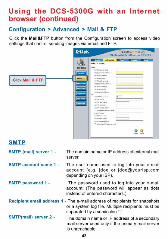
Using the DCS-5300G with an Internetbrowser (continued)Configuration > Advanced > Mail & FTPClick the Mail&FTP button from the Configuration screen to access videosettings that control sending images via email and FTP.
SMTPSMTP (mail) server 1 - The domain name or IP address of external mail
server.
SMTP account name 1 - The user name used to log into your e-mailaccount (e.g. jdoe or [email protected] on your ISP).
SMTP password 1 - The password used to log into your e-mailaccount. (The password will appear as dotsinstead of entered characters.)
Recipient email address 1 - The e-mail address of recipients for snapshotsor a system log file. Multiple recipients must beseparated by a semicolon “;”
SMTP(mail) server 2 - The domain name or IP address of a secondarymail server used only if the primary mail serveris unreachable.
Click Mail & FTP
43
Using the DCS-5300G with an Internetbrowser (continued)Configuration > Advanced > Mail & FTP (Continued)
FTP Settings
1st FTP server -
Granted folder on the external FTP server. Thestring must conform to the external FTP server.Some FTP servers cannot accept a precedingslash symbol before the path if there is no virtualpath mapping. Refer to the instructions of theexternal FTP server for details. The folder privilegemust be open for upload.
1st FTP remote folder -Granted password on the external FTP server.Granted user name on the external FTP server.1st FTP user name -
The domain name or IP address of the externalFTP server. The following user settings must becorrectly configured for remote access.
Can be other than default port 21. If you find thatyou want to change the port to a port numberother than 21, you will need to specify the portwhen connecting to the FTP server. For exampleFTP://68.5.1.81:60 (if you are to use port 60 foryour FTP server port)
Local FTP server port -
1st FTP password -
The e-mail address of recipients for thesecondary server.
The return e-mail address to use if thesnapshot or system log e-mail fails to send.(This address should be within the SMTPserver’s domain for authentication purposes.)
Return email address -
Recipient email address 2 -
The user name for the second SMTP server.SMTP account name 2 -
The password used to log into the second e-mailaccount. (The password will appear as dotsinstead of entered characters.)
SMTP password 2 -
44
Click Apply to makechanges effective
Using the DCS-5300G with an Internetbrowser (continued)Configuration > Advanced > Mail & FTP (Continued)
2nd FTP user name - Granted user name on the backup FTP server.
2nd FTP password - Granted password on the backup FTP server.
2nd FTP server - The domain name or IP address of the externalFTP server. Note that the 2nd FTP server will onlybe used if the 1st FTP server is unavailable. Ifimage upload to the 1st FTP server is successful,no attempts will be made to connect to the 2ndFTP server.
2nd FTP remote folder - Granted folder on the backup FTP server.
Mode - Passive mode setting for the backup FTP server.Secondary FTP passive
Invalid settings may cause the DCS-5300G to not respond. Change theconfiguration settings only if necessary. Consult with your networkadministrator or your Internet Service Provider (ISP) if you do not have thenecessary information. If you cannot connect to the camera, refer to page128 for camera reset and restore factory settings procedures.
If the DCS-5300G is located inside a network thatis protected by a firewall, a data connection forFTP may be prohibited. Passive mode FTP canbypass this rule and allow the uploading ofsnapshots. If the passive mode is selected, theDCS-5300G can automatically attempt to uploadin active mode if the external FTP server doesnot support passive mode.
Primary FTP PassiveMode-
45
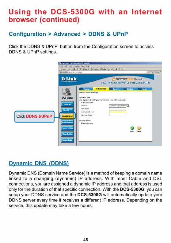
Click the DDNS & UPnP button from the Configuration screen to accessDDNS & UPnP settings.
Configuration > Advanced > DDNS & UPnP
Dynamic DNS (DDNS)Dynamic DNS (Domain Name Service) is a method of keeping a domain namelinked to a changing (dynamic) IP address. With most Cable and DSLconnections, you are assigned a dynamic IP address and that address is usedonly for the duration of that specific connection. With the DCS-5300G, you cansetup your DDNS service and the DCS-5300G will automatically update yourDDNS server every time it receives a different IP address. Depending on theservice, this update may take a few hours.
Using the DCS-5300G with an Internetbrowser (continued)
Click DDNS &UPnP
46
Enable DDNS - Click to enable the DDNS function.
Provider- Select your Dynamic DNS provider from the pulldown menu.
Host name- Enter the host name of the DDNS server.
Username/E-mail-
Password/Key- Enter your password or key used to connect tothe DDNS server.
Configuration > Advanced > DDNS & UPnP (Continued)
Enter your username or e-mail used to connect tothe DDNS server.
UPnP
UPnP is short for Universal Plug and Play, which is a networking architecturethat provides compatibility among networking equipment, software, andperipherals. The DCS-5300G is a UPnP enabled internet camera. If youroperating system is UPnP enabled, the device will be easier to configure. If youdo not want to use the UPnP functionality, it can be disabled by unselecting“Enable UPnP.”
Click Apply to makechanges effective
Using the DCS-5300G with an Internetbrowser (continued)
47
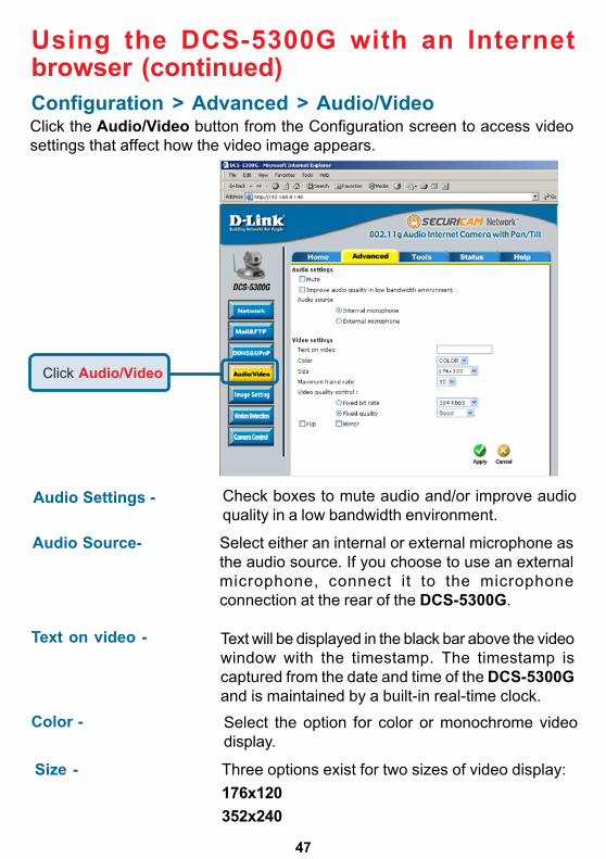
Click the Audio/Video button from the Configuration screen to access videosettings that affect how the video image appears.
Configuration > Advanced > Audio/Video
Using the DCS-5300G with an Internetbrowser (continued)
Three options exist for two sizes of video display:176x120352x240
Text will be displayed in the black bar above the videowindow with the timestamp. The timestamp iscaptured from the date and time of the DCS-5300Gand is maintained by a built-in real-time clock.
Select the option for color or monochrome videodisplay.
Text on video -
Size -
Color -
Audio Settings - Check boxes to mute audio and/or improve audioquality in a low bandwidth environment.
Audio Source- Select either an internal or external microphone asthe audio source. If you choose to use an externalmicrophone, connect it to the microphoneconnection at the rear of the DCS-5300G.
Click Audio/Video
48
Configuration > Advanced > Audio/Video (Continued)
Using the DCS-5300G with an Internetbrowser (continued)
Maximum frame rate-
Video quality control-
Flip - Vertically rotate the video.
Limits the maximum refresh frame rate. The framerate is used with the Video quality control setting(below) to optimize bandwidth utilization and videoquality.
To fix the bandwidth utilization regardless of the videoquality, choose Fix bit rate and select the desiredbandwidth. The video quality may be reduced inorder to send maximum frames with limitedbandwidth, especially when images changedrastically. For higher video detail regardless of thebandwidth selection, select Fix quality and selecta video quality level. This setting will utilize morebandwidth to send the maximum frames whenimages change drastically.
Mirror - Horizontally rotate the video. Check both flip and mirror if the DCS-5300G is to be installed upside down.
White balance - Choose the suitable option for the best color temperature.
Click Apply to makechanges effective
704x480In 704x480 mode, the frame rate will be reduced to10 fps and increased to 30 fps when it is switchedback to a lower image size.
49
Using the DCS-5300G with an Internetbrowser (continued)
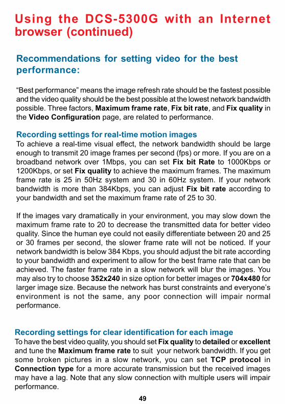
Recording settings for clear identification for each imageTo have the best video quality, you should set Fix quality to detailed or excellentand tune the Maximum frame rate to suit your network bandwidth. If you getsome broken pictures in a slow network, you can set TCP protocol inConnection type for a more accurate transmission but the received imagesmay have a lag. Note that any slow connection with multiple users will impairperformance.
Recommendations for setting video for the bestperformance:
“Best performance” means the image refresh rate should be the fastest possibleand the video quality should be the best possible at the lowest network bandwidthpossible. Three factors, Maximum frame rate, Fix bit rate, and Fix quality inthe Video Configuration page, are related to performance.
Recording settings for real-time motion imagesTo achieve a real-time visual effect, the network bandwidth should be largeenough to transmit 20 image frames per second (fps) or more. If you are on abroadband network over 1Mbps, you can set Fix bit Rate to 1000Kbps or1200Kbps, or set Fix quality to achieve the maximum frames. The maximumframe rate is 25 in 50Hz system and 30 in 60Hz system. If your networkbandwidth is more than 384Kbps, you can adjust Fix bit rate according toyour bandwidth and set the maximum frame rate of 25 to 30.
If the images vary dramatically in your environment, you may slow down themaximum frame rate to 20 to decrease the transmitted data for better videoquality. Since the human eye could not easily differentiate between 20 and 25or 30 frames per second, the slower frame rate will not be noticed. If yournetwork bandwidth is below 384 Kbps, you should adjust the bit rate accordingto your bandwidth and experiment to allow for the best frame rate that can beachieved. The faster frame rate in a slow network will blur the images. Youmay also try to choose 352x240 in size option for better images or 704x480 forlarger image size. Because the network has burst constraints and everyone’senvironment is not the same, any poor connection will impair normalperformance.
50
Recommendations for setting video for the bestperformance (continued):
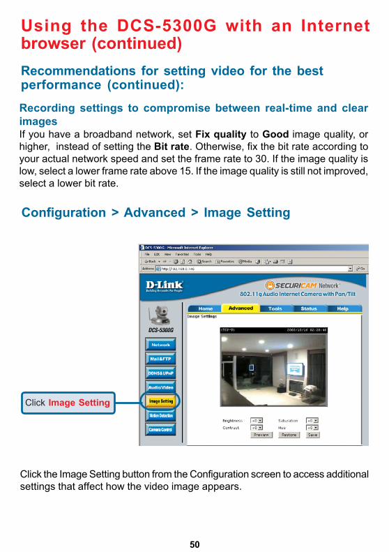
Recording settings to compromise between real-time and clearimagesIf you have a broadband network, set Fix quality to Good image quality, orhigher, instead of setting the Bit rate. Otherwise, fix the bit rate according toyour actual network speed and set the frame rate to 30. If the image quality islow, select a lower frame rate above 15. If the image quality is still not improved,select a lower bit rate.
Click the Image Setting button from the Configuration screen to access additionalsettings that affect how the video image appears.
Using the DCS-5300G with an Internetbrowser (continued)
Configuration > Advanced > Image Setting
Click Image Setting
51
Configuration > Advanced > Motion Detection
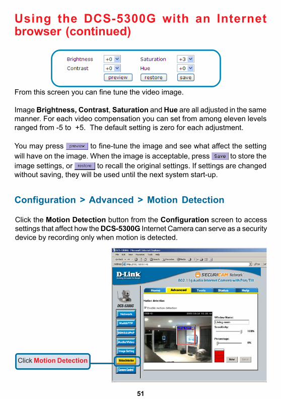
Click the Motion Detection button from the Configuration screen to accesssettings that affect how the DCS-5300G Internet Camera can serve as a securitydevice by recording only when motion is detected.
Using the DCS-5300G with an Internetbrowser (continued)
From this screen you can fine tune the video image.
Image Brightness, Contrast, Saturation and Hue are all adjusted in the samemanner. For each video compensation you can set from among eleven levelsranged from -5 to +5. The default setting is zero for each adjustment.
You may press to fine-tune the image and see what affect the settingwill have on the image. When the image is acceptable, press to store theimage settings, or to recall the original settings. If settings are changedwithout saving, they will be used until the next system start-up.
Click Motion Detection
52
Configuration > Advanced >Motion Detection (continued)
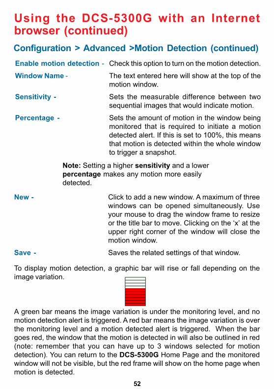
A green bar means the image variation is under the monitoring level, and nomotion detection alert is triggered. A red bar means the image variation is overthe monitoring level and a motion detected alert is triggered. When the bargoes red, the window that the motion is detected in will also be outlined in red(note: remember that you can have up to 3 windows selected for motiondetection). You can return to the DCS-5300G Home Page and the monitoredwindow will not be visible, but the red frame will show on the home page whenmotion is detected.
New - Click to add a new window. A maximum of threewindows can be opened simultaneously. Useyour mouse to drag the window frame to resizeor the title bar to move. Clicking on the ‘x’ at theupper right corner of the window will close themotion window.
Save - Saves the related settings of that window.
Using the DCS-5300G with an Internetbrowser (continued)
Enable motion detection - Check this option to turn on the motion detection.
Window Name - The text entered here will show at the top of themotion window.
Sensitivity - Sets the measurable difference between twosequential images that would indicate motion.
Percentage - Sets the amount of motion in the window beingmonitored that is required to initiate a motiondetected alert. If this is set to 100%, this meansthat motion is detected within the whole windowto trigger a snapshot.
Note: Setting a higher sensitivity and a lowerpercentage makes any motion more easilydetected.
To display motion detection, a graphic bar will rise or fall depending on theimage variation.
53
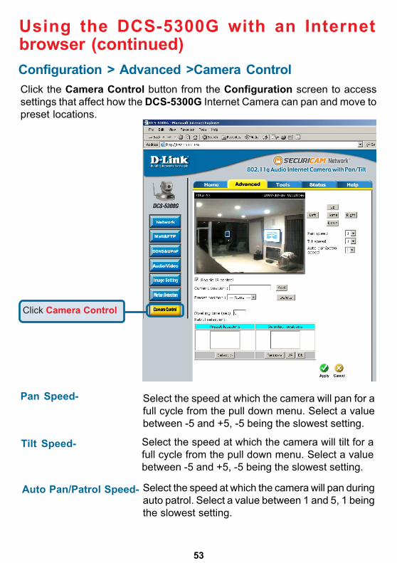
Configuration > Advanced >Camera Control
Using the DCS-5300G with an Internetbrowser (continued)
Click the Camera Control button from the Configuration screen to accesssettings that affect how the DCS-5300G Internet Camera can pan and move topreset locations.
Click Camera Control
Pan Speed- Select the speed at which the camera will pan for afull cycle from the pull down menu. Select a valuebetween -5 and +5, -5 being the slowest setting.
Tilt Speed- Select the speed at which the camera will tilt for afull cycle from the pull down menu. Select a valuebetween -5 and +5, -5 being the slowest setting.
Auto Pan/Patrol Speed- Select the speed at which the camera will pan duringauto patrol. Select a value between 1 and 5, 1 beingthe slowest setting.
54
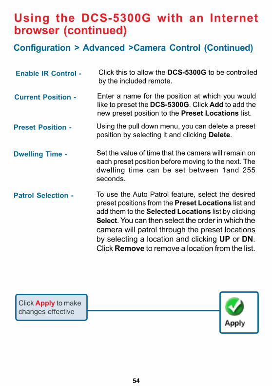
Enable IR Control - Click this to allow the DCS-5300G to be controlledby the included remote.
Configuration > Advanced >Camera Control (Continued)
Using the DCS-5300G with an Internetbrowser (continued)
Current Position - Enter a name for the position at which you wouldlike to preset the DCS-5300G. Click Add to add thenew preset position to the Preset Locations list.
Preset Position - Using the pull down menu, you can delete a presetposition by selecting it and clicking Delete.
Dwelling Time - Set the value of time that the camera will remain oneach preset position before moving to the next. Thedwelling time can be set between 1and 255seconds.
Patrol Selection - To use the Auto Patrol feature, select the desiredpreset positions from the Preset Locations list andadd them to the Selected Locations list by clickingSelect. You can then select the order in which thecamera will patrol through the preset locationsby selecting a location and clicking UP or DN.Click Remove to remove a location from the list.
Click Apply to makechanges effective
55
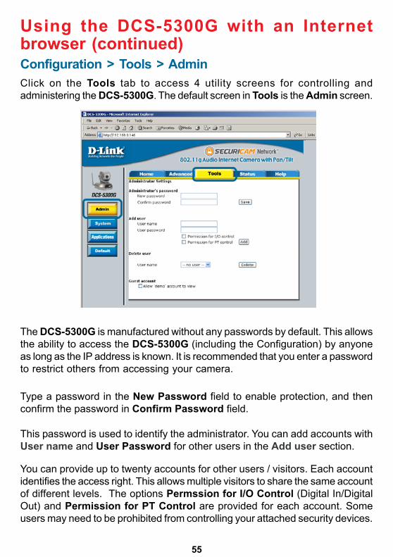
Configuration > Tools > AdminClick on the Tools tab to access 4 utility screens for controlling andadministering the DCS-5300G. The default screen in Tools is the Admin screen.
The DCS-5300G is manufactured without any passwords by default. This allowsthe ability to access the DCS-5300G (including the Configuration) by anyoneas long as the IP address is known. It is recommended that you enter a passwordto restrict others from accessing your camera.
Type a password in the New Password field to enable protection, and thenconfirm the password in Confirm Password field.
This password is used to identify the administrator. You can add accounts withUser name and User Password for other users in the Add user section.
Using the DCS-5300G with an Internetbrowser (continued)
You can provide up to twenty accounts for other users / visitors. Each accountidentifies the access right. This allows multiple visitors to share the same accountof different levels. The options Permssion for I/O Control (Digital In/DigitalOut) and Permission for PT Control are provided for each account. Someusers may need to be prohibited from controlling your attached security devices.
56
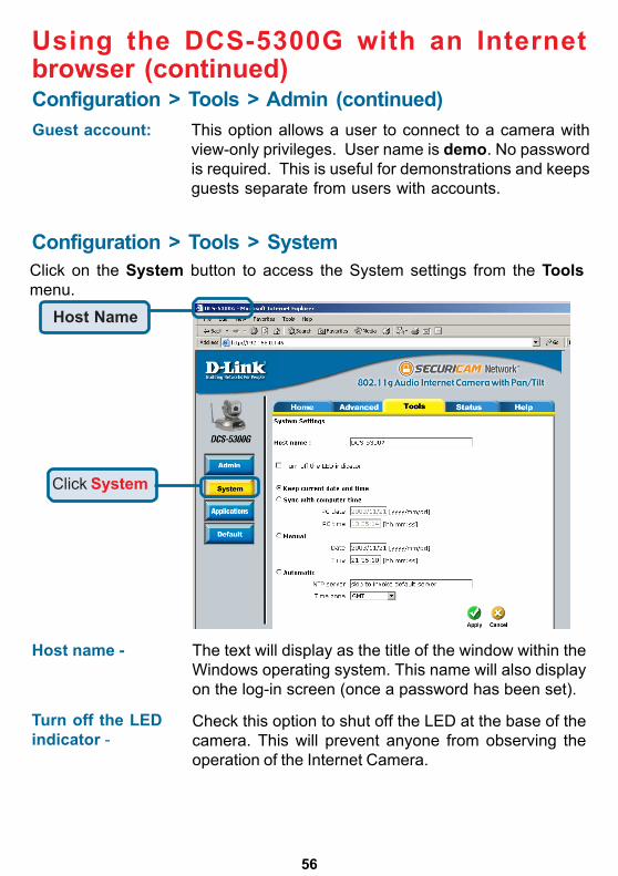
Guest account: This option allows a user to connect to a camera withview-only privileges. User name is demo. No passwordis required. This is useful for demonstrations and keepsguests separate from users with accounts.
Configuration > Tools > SystemClick on the System button to access the System settings from the Toolsmenu.
Host name -
Using the DCS-5300G with an Internetbrowser (continued)
Check this option to shut off the LED at the base of thecamera. This will prevent anyone from observing theoperation of the Internet Camera.
The text will display as the title of the window within theWindows operating system. This name will also displayon the log-in screen (once a password has been set).
Turn off the LEDindicator -
Configuration > Tools > Admin (continued)
Click System
Host Name
57
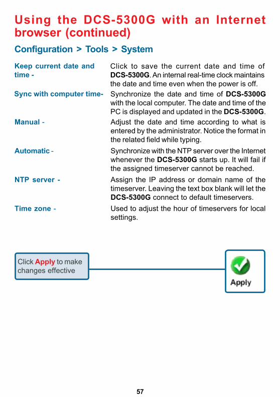
Configuration > Tools > System
Manual - Adjust the date and time according to what isentered by the administrator. Notice the format inthe related field while typing.
Automatic - Synchronize with the NTP server over the Internetwhenever the DCS-5300G starts up. It will fail ifthe assigned timeserver cannot be reached.
NTP server - Assign the IP address or domain name of thetimeserver. Leaving the text box blank will let theDCS-5300G connect to default timeservers.
Time zone - Used to adjust the hour of timeservers for localsettings.
Keep current date andtime -
Using the DCS-5300G with an Internetbrowser (continued)
Click to save the current date and time ofDCS-5300G. An internal real-time clock maintainsthe date and time even when the power is off.
Sync with computer time-
Click Apply to makechanges effective
Synchronize the date and time of DCS-5300Gwith the local computer. The date and time of thePC is displayed and updated in the DCS-5300G.
58
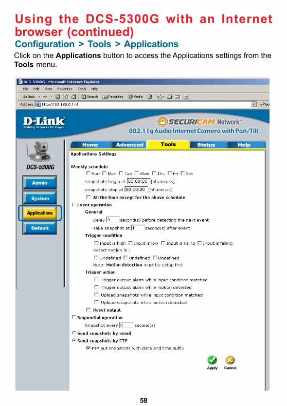
Configuration > Tools > Applications
Using the DCS-5300G with an Internetbrowser (continued)
Click on the Applications button to access the Applications settings from theTools menu.
59
Configuration > Tools > Applications (Continued)Weekly schedule:Sunday through Saturday - Select the weekdays that should perform the
following operations:
Snapshots begin at -
Snapshots stop at - Sets the time to stop the operations.
All of the time except forthe above schedule - If you do not wish to set a schedule, this box must
be checked.
Using the DCS-5300G with an Internetbrowser (continued)
Set the time to start operations. Setting thebegin time the same as the stop time willforce the operations to run continuously.
Delay second(s) beforedetecting next event - Sets the time delay before restarting to check the
trigger condition when the current condition istriggered.
Take snapshots atsecond(s) after event - After a snapshot is taken because of a trigger,
another snapshot will be taken after theconfigured time in seconds.
Trigger condition - There are 4 conditions related to the digital inputand three windows for motion detection. Therecan be multiple selections. Select the appropriatedigital input condition according to thecharacteristics of the external device. High or lowindicate external voltage input for level trigger,while rising or falling is for edge triggers. Thereare three windows shown for the names youdefined for motion detection. Undefined willshow instead of the window title if motiondetection is not setup yet. An active, namedmotion window must be checked for motiondetection to be possible.
Reset output - Check and save this option to reset the externaldevice at the digital output back to the originalstate.
Event operation:
60
Configuration > Tools > Applications (Continued)
Trigger action - There are four options for two actions regardingeither trigger condition. They can have multipleselections. While choosing the trigger outputalarm, the digital output will short both pins toconnect the circuit of the attached externaldevice; otherwise both pins will be open. Whilechoosing to upload snapshots, the method canbe either email or FTP. The snapshot names willbe “videopre.jpg”, videotrg.jpg”, and“videopos.jpg” respectively for the snapshotsbefore event, right upon event, and after event.The date and time suffix may be added accordingto the option. Confirm the external mail or FTPserver settings in network configuration.
Sequential operation
Using the DCS-5300G with an Internetbrowser (continued)
Snapshot every The camera will send snapshots at the specifiedinterval to the external server according to thechosen method. Remember this operation isdependent to the weekly schedule.
Send snapshots by email - Any upload action specified in the options abovewill use the method chosen here. The capturedsnapshot named “video.jpg” will be attached inthe email with subject “Periodic snapshots.”
Send snapshots by FTP - The captured snapshots will upload to theexternal FTP server with the file name dependingon the next option.
second(s) -
61
Configuration > Tools > Applications (Continued)
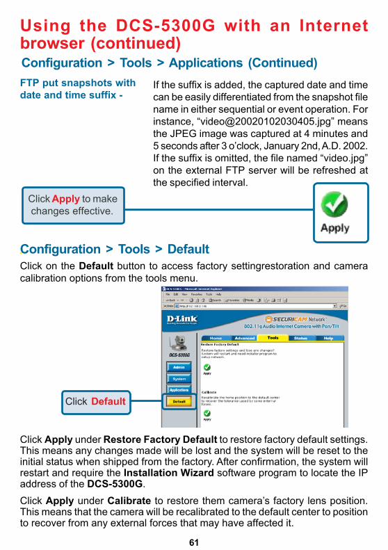
Click on the Default button to access factory settingrestoration and cameracalibration options from the tools menu.
Click Apply under Restore Factory Default to restore factory default settings.This means any changes made will be lost and the system will be reset to theinitial status when shipped from the factory. After confirmation, the system willrestart and require the Installation Wizard software program to locate the IPaddress of the DCS-5300G.
Using the DCS-5300G with an Internetbrowser (continued)
Click Apply to make changes effective.
Configuration > Tools > Default
FTP put snapshots withdate and time suffix -
If the suffix is added, the captured date and timecan be easily differentiated from the snapshot filename in either sequential or event operation. Forinstance, “[email protected]” meansthe JPEG image was captured at 4 minutes and5 seconds after 3 o’clock, January 2nd, A.D. 2002.If the suffix is omitted, the file named “video.jpg”on the external FTP server will be refreshed atthe specified interval.
Click Default
Click Apply under Calibrate to restore them camera’s factory lens position.This means that the camera will be recalibrated to the default center to positionto recover from any external forces that may have affected it.
62
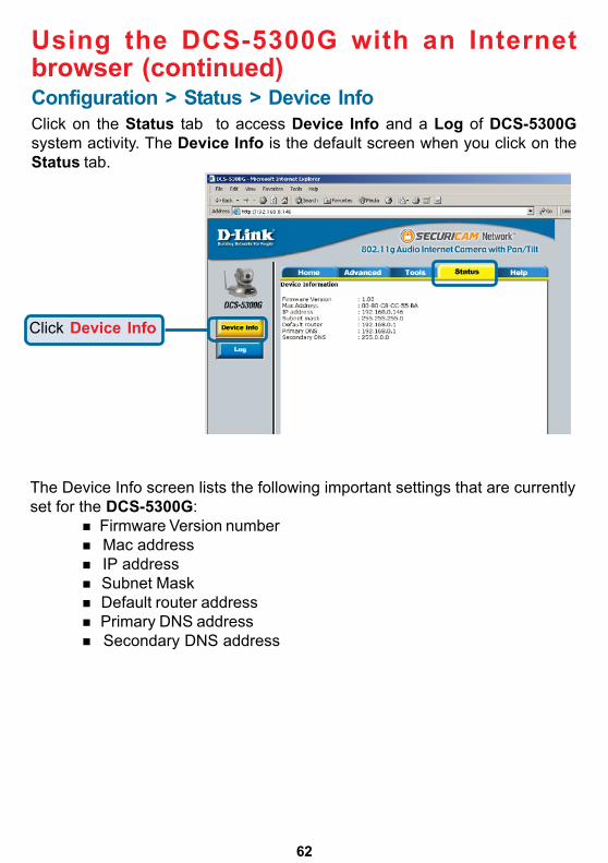
The Device Info screen lists the following important settings that are currentlyset for the DCS-5300G:
Firmware Version number Mac address IP address Subnet Mask Default router address Primary DNS address Secondary DNS address
Using the DCS-5300G with an Internetbrowser (continued)Configuration > Status > Device InfoClick on the Status tab to access Device Info and a Log of DCS-5300Gsystem activity. The Device Info is the default screen when you click on theStatus tab.
Click Device Info
63
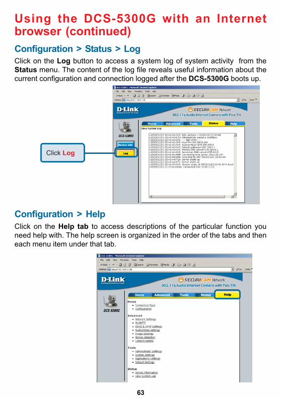
Click on the Help tab to access descriptions of the particular function youneed help with. The help screen is organized in the order of the tabs and theneach menu item under that tab.
Configuration > Help
Using the DCS-5300G with an Internetbrowser (continued)Configuration > Status > LogClick on the Log button to access a system log of system activity from theStatus menu. The content of the log file reveals useful information about thecurrent configuration and connection logged after the DCS-5300G boots up.
Click Log
64
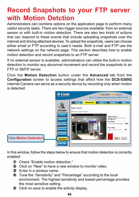
Record Snapshots to your FTP serverwith Motion DetctionAdministrators can combine options on the application page to perform manyuseful security tasks. There are two trigger sources available: from an externalsensor or with built-in motion detection. There are also two kinds of actionsthat can respond to these events that include uploading snapshots over theinternet and driving attached devices. To upload the snapshots, users can chooseeither email or FTP according to user’s needs. Both e-mail and FTP use thenetwork settings on the network page. This section describes how to enablemotion detection and record snapshots to an FTP server.If no external sensor is available, administrators can utilize the built-in motiondetection to monitor any abnormal movement and record the snapshots to anFTP or SMTP server.
In this window, follow the steps below to ensure that motion detection is correctlyenabled:
Check “Enable motion detection.”Click on “New” to have a new window to monitor video.Enter in a window name.Tune the “Sensitivity” and “Percentage” according to the localenvironment. The highest sensitivity and lowest percentage providesthe most sensitive setting.
55555 Click on save to enable the activity display.
Click the Motion Detection button under the Advanced tab from theConfiguration screen to access settings that affect how the DCS-5300GInternet Camera can serve as a security device by recording only when motionis detected.
Click Motion Detection
65
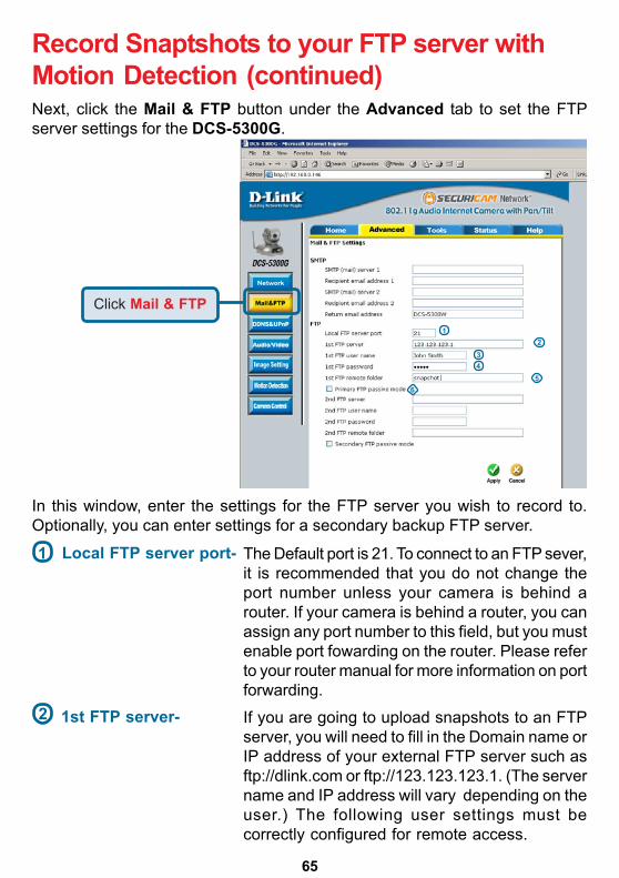
Next, click the Mail & FTP button under the Advanced tab to set the FTPserver settings for the DCS-5300G.
Record Snaptshots to your FTP server withMotion Detection (continued)
In this window, enter the settings for the FTP server you wish to record to.Optionally, you can enter settings for a secondary backup FTP server.
Local FTP server port- The Default port is 21. To connect to an FTP sever,it is recommended that you do not change theport number unless your camera is behind arouter. If your camera is behind a router, you canassign any port number to this field, but you mustenable port fowarding on the router. Please referto your router manual for more information on portforwarding.
1st FTP server- If you are going to upload snapshots to an FTPserver, you will need to fill in the Domain name orIP address of your external FTP server such asftp://dlink.com or ftp://123.123.123.1. (The servername and IP address will vary depending on theuser.) The following user settings must becorrectly configured for remote access.
1
2
Click Mail & FTP1
5
2
43
6
66
Record Snaptshots to your FTP server withMotion Detection (continued)
1st FTP password- Specify the password to access the external FTPserver (ex. 12345).
1st FTP remote folder- Specify the destination folder in the external FTPserver (ex. snapshot).
Primary FTP passivemode-
Passive mode will allow access to an externalFTP server if your camera is behind a routerprotected by a firewall.
2nd FTP server- Specify the Domain name or IP address of yoursecond external FTP server. This field is optionalif you have already filled in the information for thefirst FTP server.
2nd FTP user name- Specify the user name to access your backupFTP server.
2nd FTP password- Specify the user password to your backup FTPserver.
2nd FTP remote folder- Specify the destination folder on your externalbackup FTP server.
For detailed information about each setting, please refer to Configuration >Adanced > Mail & FTP in the section titled “Using the DCS-5300G With anInternet Browser” (page 42). Click the apply button when finished.
Secondary FTP passivemode-
Passive mode will allow access to a secondexternal FTP server if your camera is behind arouter protected by a firewall.
1st FTP user name- Specify the user name to access the external FTPserver (ex. John Smith).
3
4
5
6
67
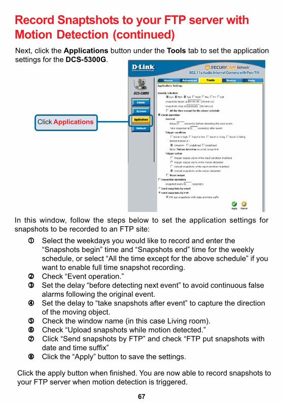
Next, click the Applications button under the Tools tab to set the applicationsettings for the DCS-5300G.
In this window, follow the steps below to set the application settings forsnapshots to be recorded to an FTP site:
Select the weekdays you would like to record and enter the “Snapshots begin” time and “Snapshots end” time for the weekly schedule, or select “All the time except for the above schedule” if you want to enable full time snapshot recording. Check “Event operation.” Set the delay “before detecting next event” to avoid continuous false alarms following the original event. Set the delay to “take snapshots after event” to capture the direction
of the moving object.55555 Check the window name (in this case Living room).66666 Check “Upload snapshots while motion detected.”77777 Click “Send snapshots by FTP” and check “FTP put snapshots with
date and time suffix”88888 Click the “Apply” button to save the settings.
Click the apply button when finished. You are now able to record snapshots toyour FTP server when motion detection is triggered.
Click Applications
Record Snaptshots to your FTP server withMotion Detection (continued)
X X X
X
X
X
Living room
68
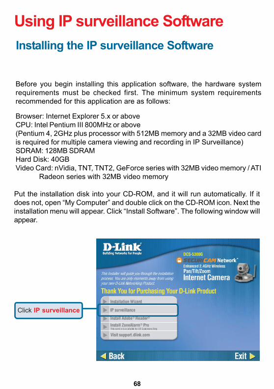
Using IP surveillance SoftwareInstalling the IP surveillance Software
Before you begin installing this application software, the hardware systemrequirements must be checked first. The minimum system requirementsrecommended for this application are as follows:
Browser: Internet Explorer 5.x or aboveCPU: Intel Pentium III 800MHz or above(Pentium 4, 2GHz plus processor with 512MB memory and a 32MB video cardis required for multiple camera viewing and recording in IP Surveillance)SDRAM: 128MB SDRAMHard Disk: 40GBVideo Card: nVidia, TNT, TNT2, GeForce series with 32MB video memory / ATI
Radeon series with 32MB video memory
Put the installation disk into your CD-ROM, and it will run automatically. If itdoes not, open “My Computer” and double click on the CD-ROM icon. Next theinstallation menu will appear. Click “Install Software”. The following window willappear.
Click IP surveillance
69
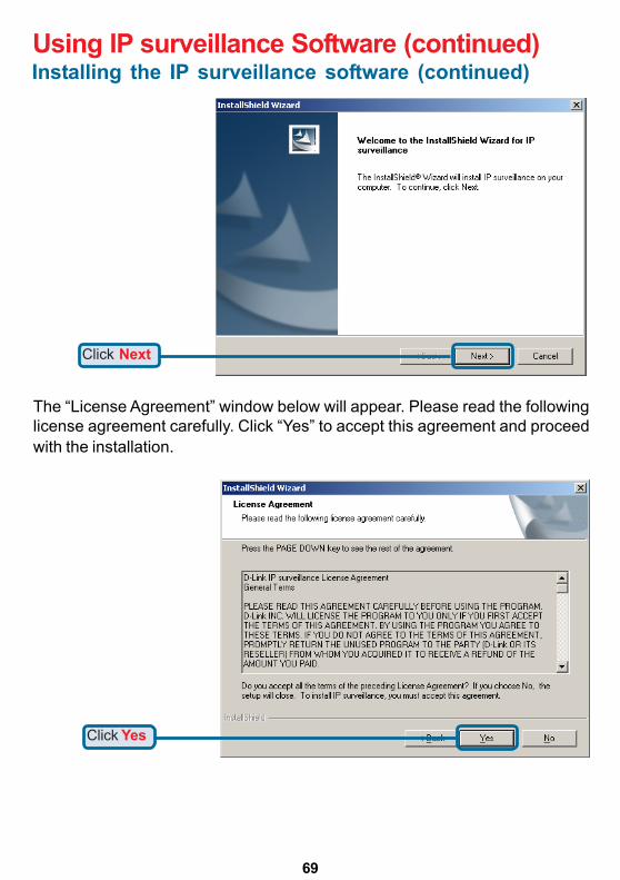
Using IP surveillance Software (continued)
The “License Agreement” window below will appear. Please read the followinglicense agreement carefully. Click “Yes” to accept this agreement and proceedwith the installation.
Click Next
Click Yes
Installing the IP surveillance software (continued)
70
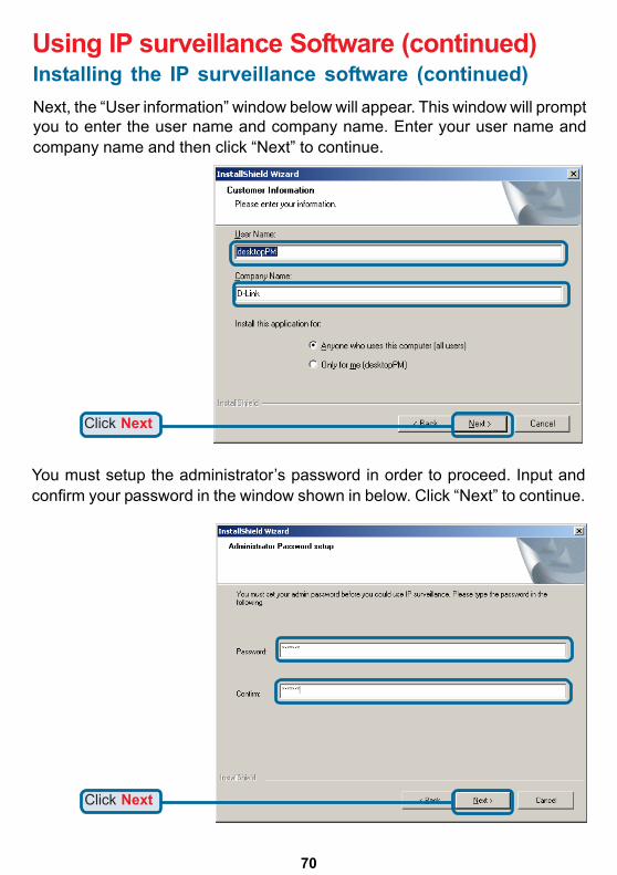
Using IP surveillance Software (continued)
Next, the “User information” window below will appear. This window will promptyou to enter the user name and company name. Enter your user name andcompany name and then click “Next” to continue.
Click Next
You must setup the administrator’s password in order to proceed. Input andconfirm your password in the window shown in below. Click “Next” to continue.
Click Next
Installing the IP surveillance software (continued)
71
Using IP surveillance Software (continued)
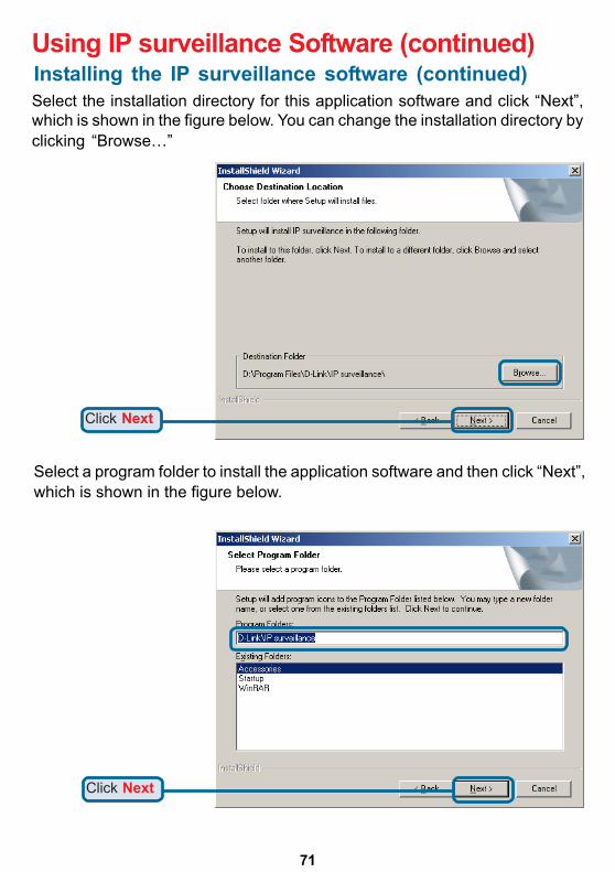
Select the installation directory for this application software and click “Next”,which is shown in the figure below. You can change the installation directory byclicking “Browse…”
Click Next
Select a program folder to install the application software and then click “Next”,which is shown in the figure below.
Click Next
Installing the IP surveillance software (continued)
72
Using IP surveillance Software (continued)
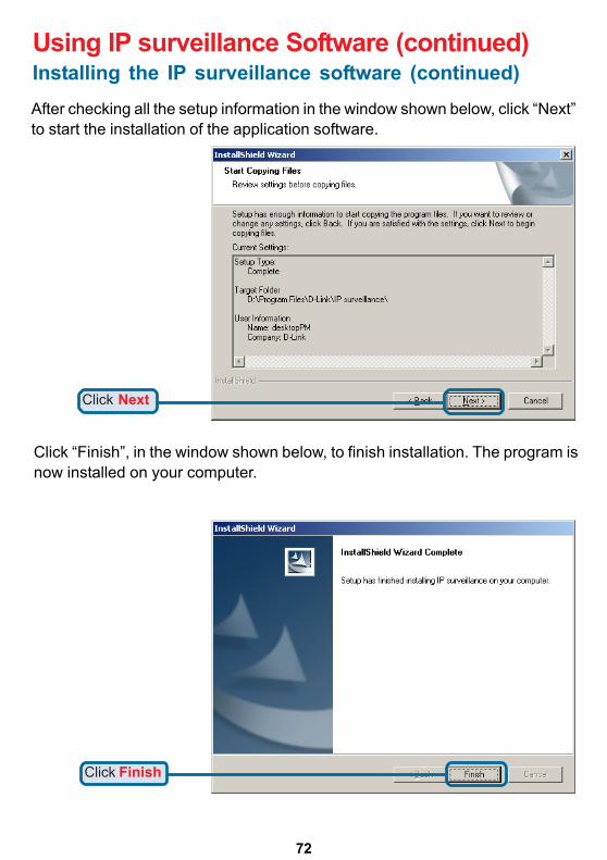
After checking all the setup information in the window shown below, click “Next”to start the installation of the application software.
Click Next
Click Finish
Click “Finish”, in the window shown below, to finish installation. The program isnow installed on your computer.
Installing the IP surveillance software (continued)
73
Using IP surveillance Software (continued)
LauncherLauncher is a controller program that allows users to invoke Monitor or Playbackquickly.
System Tray IconThe Launcher icon reflects current state of IP surveillance. The icon in thesystem tray signifies that the IP surveillance Software is currently active on thesystem.
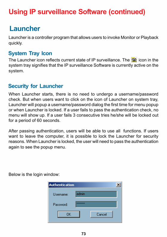
Security for LauncherWhen Launcher starts, there is no need to undergo a username/passwordcheck. But when users want to click on the icon of Launcher on system tray,Launcher will popup a username/password dialog the first time for menu popupor when Launcher is locked. If a user fails to pass the authentication check, nomenu will show up. If a user fails 3 consecutive tries he/she will be locked outfor a period of 60 seconds.
After passing authentication, users will be able to use all functions. If userswant to leave the computer, it is possible to lock the Launcher for securityreasons. When Launcher is locked, the user will need to pass the authenticationagain to see the popup menu.
Below is the login window:
74
Using IP surveillance Software (continued)
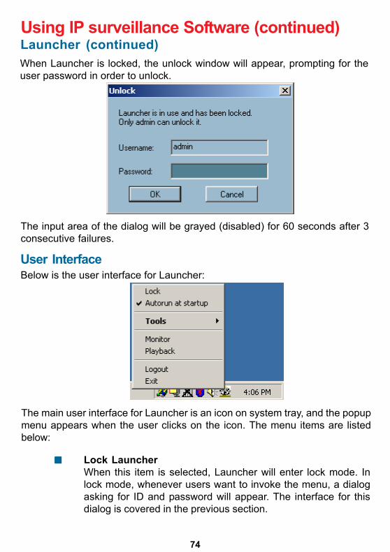
When Launcher is locked, the unlock window will appear, prompting for theuser password in order to unlock.
The input area of the dialog will be grayed (disabled) for 60 seconds after 3consecutive failures.
User InterfaceBelow is the user interface for Launcher:
The main user interface for Launcher is an icon on system tray, and the popupmenu appears when the user clicks on the icon. The menu items are listedbelow:
Lock LauncherWhen this item is selected, Launcher will enter lock mode. Inlock mode, whenever users want to invoke the menu, a dialogasking for ID and password will appear. The interface for thisdialog is covered in the previous section.
Launcher (continued)
75
Using IP surveillance Software (continued)
ExitExits Launcher. If users choose this option, Launcher will show amessage box prompting to confirm if users really want to exit,and warn users that exiting Launcher will also close Monitor andPlayback.
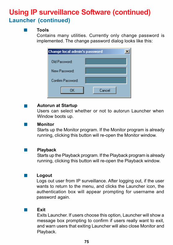
ToolsContains many utilities. Currently only change password isimplemented. The change password dialog looks like this:
Autorun at StartupUsers can select whether or not to autorun Launcher whenWindow boots up.
MonitorStarts up the Monitor program. If the Monitor program is alreadyrunning, clicking this button will re-open the Monitor window.
PlaybackStarts up the Playback program. If the Playback program is alreadyrunning, clicking this button will re-open the Playback window.
LogoutLogs out user from IP surveillance. After logging out, if the userwants to return to the menu, and clicks the Launcher icon, theauthentication box will appear prompting for username andpassword again.
Launcher (continued)
76
Monitor ProgramFeatures of the Monitor ProgramTraditional Surveillance Features:
Real-time monitoring
RecordingPan and Tilt control
Using IP surveillance Software (continued)
Special Features:The digital surveillance system supports not only the features listed above, butalso the following features, which make the system more powerful andconvenient.
Simultaneous real-time monitoring and recording audio and video
High quality video up to full screen display
High compression ratio
Maximum of 16 cameras with different monitor layouts
Auto alarm in multiple modes
Account-password protection
Multiple recording modes: Event-driven, Scheduled, and manualrecording for each camera.
Just-in-time snapshot
Motion detection with 3 alert windows for each camera
77
Using IP surveillance Software (continued)
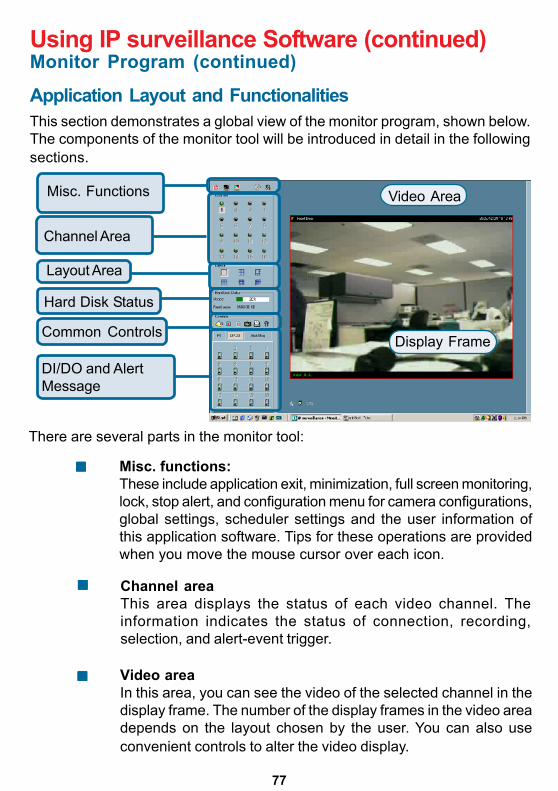
Application Layout and FunctionalitiesThis section demonstrates a global view of the monitor program, shown below.The components of the monitor tool will be introduced in detail in the followingsections.
Misc. Functions
Channel Area
Hard Disk Status
Layout Area
Common Controls
DI/DO and AlertMessage
Display Frame
Video Area
There are several parts in the monitor tool:
Misc. functions:These include application exit, minimization, full screen monitoring,lock, stop alert, and configuration menu for camera configurations,global settings, scheduler settings and the user information ofthis application software. Tips for these operations are providedwhen you move the mouse cursor over each icon.
Channel areaThis area displays the status of each video channel. Theinformation indicates the status of connection, recording,selection, and alert-event trigger.
Video areaIn this area, you can see the video of the selected channel in thedisplay frame. The number of the display frames in the video areadepends on the layout chosen by the user. You can also useconvenient controls to alter the video display.
Monitor Program (continued)
78
Using IP surveillance Software (continued)
Layout areaYou can change the monitoring layout in this area. There are sixkinds of layouts: 1, 4, 6, 9, 13, or 16 video display windows in thevideo area.
Hard disk statusIn this area, you can get the status of the hard disk in which thevideo database resides. The status reminds you to arrange theavailable storage size of the recorded video database.
Common control areaThis area includes volume control, manual recording, videoprinting, snapshot, and trash can to remove video from displaywindows.
DI/DO controlThis tool receives the digital input signal and sends digital outputsignal to the remote Video Server/ Network Camera seriesproduct associated with the dedicated video channel.
Alert MessageThis tool will display the latest alert messages received by theremote Video Server / Network Camera series product associatedwith the selected video channel.
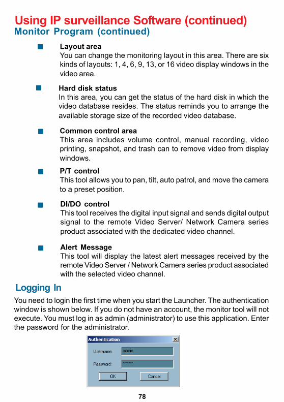
Logging InYou need to login the first time when you start the Launcher. The authenticationwindow is shown below. If you do not have an account, the monitor tool will notexecute. You must log in as admin (administrator) to use this application. Enterthe password for the administrator.
Monitor Program (continued)
P/T controlThis tool allows you to pan, tilt, auto patrol, and move the camerato a preset position.
79
Using IP surveillance Software (continued)
The Admin PrivilegeIn the monitor program, the admin has the right to access the DCS-5300GNetwork Camera through this application software and change the local settingsas well. But the admin password for the software is not the same as the adminpassword for the Internet camera. You can change the settings of each selectedInternet camera from the monitor program only if you have the admin passwordfor the Internet camera.
If you have the admin privilege, you have the right to do the following tasks:
Run the configuration tool
Change the recording schedule
Change the local settings
Again, if you need to change the settings of the DCS-5300G, you must havethe administrator’s password for the camera itself.
Camera ConfigurationsWhen you log in for the first time, you should configure this application softwareto connect the DCS-5300G in “Configuration Menu > Camera Configurations”,shown in the figure below. You will need the admin (administrator) password ofthe camera in order to run the configuration.
Once you click “Configuration Menu > Camera Configurations” forsetting each camera, all recording processes will be stopped, indicated bya warning window popped up in advance to keep you informed.
Monitor Program (continued)
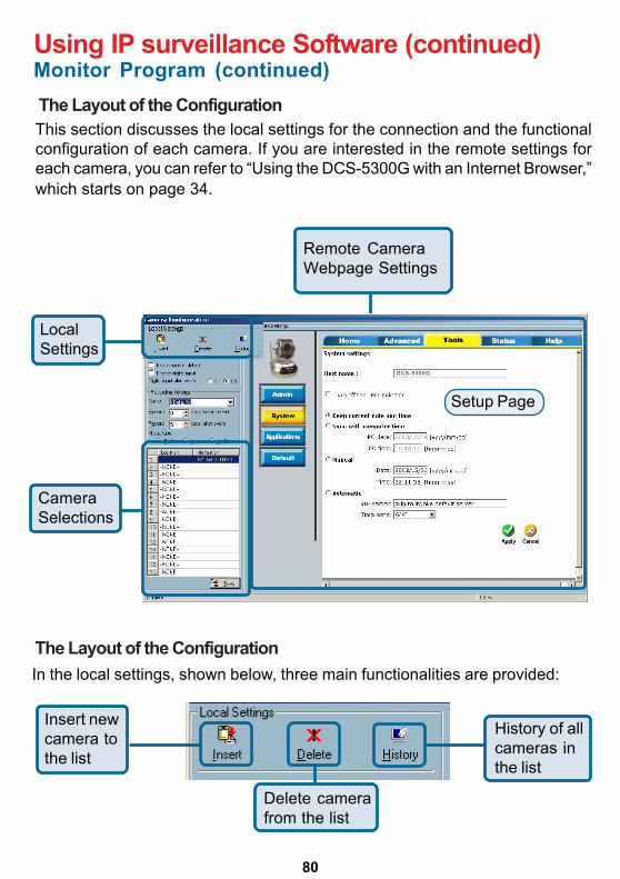
80
The Layout of the Configuration
Using IP surveillance Software (continued)
This section discusses the local settings for the connection and the functionalconfiguration of each camera. If you are interested in the remote settings foreach camera, you can refer to “Using the DCS-5300G with an Internet Browser,”which starts on page 34.
LocalSettings
CameraSelections
Remote CameraWebpage Settings
The Layout of the Configuration
In the local settings, shown below, three main functionalities are provided:
Insert newcamera tothe list
Delete camerafrom the list
History of allcameras inthe list
Monitor Program (continued)
Setup Page
DCS-5300G
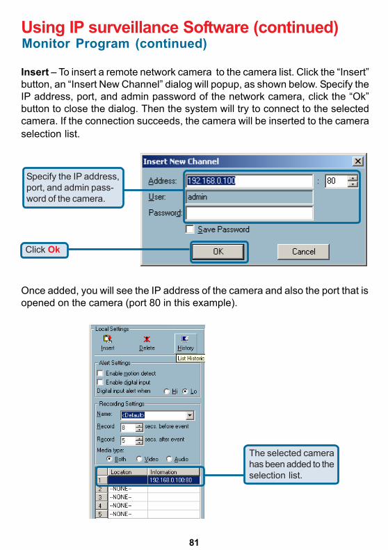
81
Using IP surveillance Software (continued)
Insert – To insert a remote network camera to the camera list. Click the “Insert”button, an “Insert New Channel” dialog will popup, as shown below. Specify theIP address, port, and admin password of the network camera, click the “Ok”button to close the dialog. Then the system will try to connect to the selectedcamera. If the connection succeeds, the camera will be inserted to the cameraselection list.
Click Ok
Specify the IP address,port, and admin pass-word of the camera.
Once added, you will see the IP address of the camera and also the port that isopened on the camera (port 80 in this example).
The selected camerahas been added to theselection list.
Monitor Program (continued)
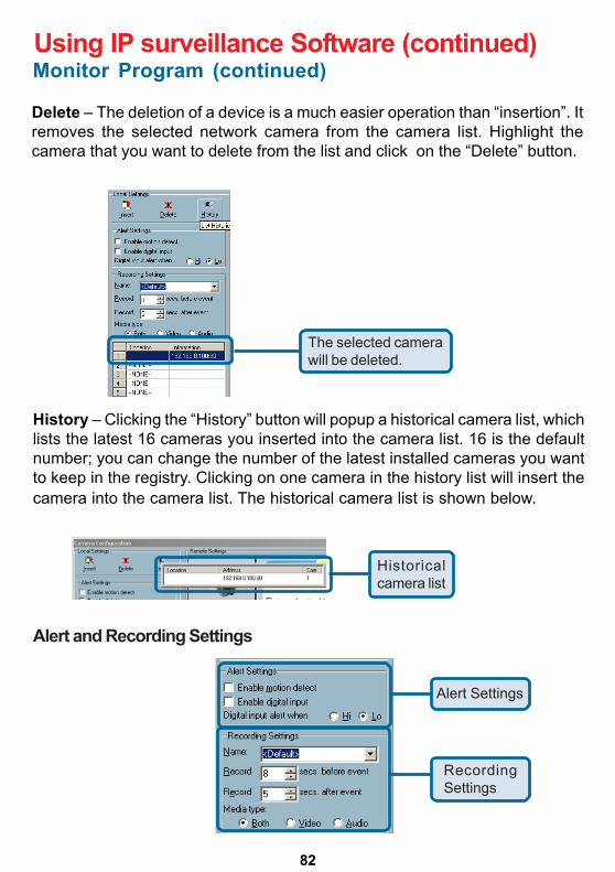
82
Delete – The deletion of a device is a much easier operation than “insertion”. Itremoves the selected network camera from the camera list. Highlight thecamera that you want to delete from the list and click on the “Delete” button.
Using IP surveillance Software (continued)
The selected camerawill be deleted.
History – Clicking the “History” button will popup a historical camera list, whichlists the latest 16 cameras you inserted into the camera list. 16 is the defaultnumber; you can change the number of the latest installed cameras you wantto keep in the registry. Clicking on one camera in the history list will insert thecamera into the camera list. The historical camera list is shown below.
Historicalcamera list
Alert and Recording Settings
Alert Settings
RecordingSettings
Monitor Program (continued)
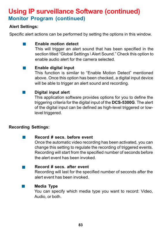
83
Using IP surveillance Software (continued)
Alert Settings:
Specific alert actions can be performed by setting the options in this window.
Enable motion detectThis will trigger an alert sound that has been specified in thesection titled “Global Settings \ Alert Sound.” Check this option toenable audio alert for the camera selected.
Enable digital inputThis function is similar to “Enable Motion Detect” mentionedabove. Once this option has been checked, a digital input devicewill be able to trigger an alert sound and recording.
Digital input alertThis application software provides options for you to define thetriggering criteria for the digital input of the DCS-5300G. The alertof the digital input can be defined as high-level triggered or low-level triggered.
Recording Settings:
Record # secs. before eventOnce the automatic video recording has been activated, you canchange this setting to regulate the recording of triggered events.Recording will start from the specified number of seconds beforethe alert event has been invoked.
Record # secs. after eventRecording will last for the specified number of seconds after thealert event has been invoked.
Media TypeYou can specify which media type you want to record: Video,Audio, or both.
Monitor Program (continued)
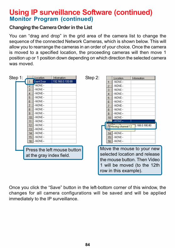
84
Changing the Camera Order in the List
Using IP surveillance Software (continued)
You can “drag and drop” in the grid area of the camera list to change thesequence of the connected Network Cameras, which is shown below. This willallow you to rearrange the cameras in an order of your choice. Once the camerais moved to a specified location, the proceeding cameras will then move 1position up or 1 position down depending on which direction the selected camerawas moved.
Step 1: Step 2:
Press the left mouse buttonat the gray index field.
Move the mouse to your newselected location and releasethe mouse button. Then Video1 will be moved (to the 12throw in this example).
Once you click the “Save” button in the left-bottom corner of this window, thechanges for all camera configurations will be saved and will be appliedimmediately to the IP surveillance.
Monitor Program (continued)
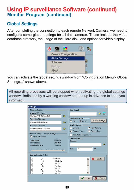
85
Using IP surveillance Software (continued)
Global SettingsAfter completing the connection to each remote Network Camera, we need toconfigure some global settings for all the cameras. These include the videodatabase directory, the usage of the Hard disk, and options for video display.
You can activate the global settings window from “Configuration Menu > GlobalSettings...” shown above.
All recording processes will be stopped when activating the global settingswindow, indicated by a warning window popped up in advance to keep youinformed.
Monitor Program (continued)
86
Using IP surveillance Software (continued)
Directory Settings:
Snapshot directoryThe directory for storing snapshost in *.bmp format from videochannels of the monitor and playback programs, which is shownon page 85.
Recording directoryThe directory for storing the recorded video data from videochannels.
Scheduler directoryThe directory for storing the default and user-customizedschedules for the scheduled recording of each channel.
Record Diskspace Usage Settings:
Cycle RecordingWhen you turn this setting on, the video database system of thisapplication software will overwrite the oldest data if the specifiedpath has become full. That means it will record video data in aloop. If this setting is unchecked, a warning message will pop upwhen it is approaching the storage space limit. All recording willstop when the limit of the hard disk usage is reached.
Reserved spaceIndicate the size of the hard disk that will be reserved for otherWindows applications (at least 15%). The remainder of the harddisk space will be available for recording. The more space youhave reserved, the less there will be available for your camera(s)to record to. As you move the bar to the right, more space will beavailable for your camera(s) and conversely, less space will beavailable for your other applications. If the recording data exceedsthis limitation, the new video data will replace the oldest data (ona First In First Out (FIFO) basis) when “Cycle Recording” hasbeen checked.
Alert SoundYou can load a custom *.wav file for the sound of alert triggering.You can also select from the sound files in Windows.
Monitor Program (continued)
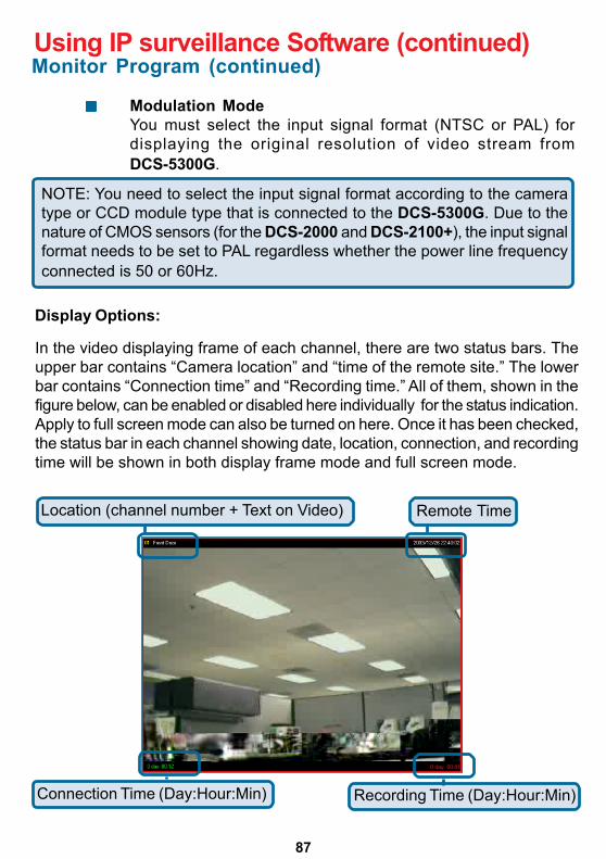
87
Using IP surveillance Software (continued)
Modulation ModeYou must select the input signal format (NTSC or PAL) fordisplaying the original resolution of video stream fromDCS-5300G.
NOTE: You need to select the input signal format according to the cameratype or CCD module type that is connected to the DCS-5300G. Due to thenature of CMOS sensors (for the DCS-2000 and DCS-2100+), the input signalformat needs to be set to PAL regardless whether the power line frequencyconnected is 50 or 60Hz.
Display Options:
In the video displaying frame of each channel, there are two status bars. Theupper bar contains “Camera location” and “time of the remote site.” The lowerbar contains “Connection time” and “Recording time.” All of them, shown in thefigure below, can be enabled or disabled here individually for the status indication.Apply to full screen mode can also be turned on here. Once it has been checked,the status bar in each channel showing date, location, connection, and recordingtime will be shown in both display frame mode and full screen mode.
0 day 00:01
Location (channel number + Text on Video) Remote Time
Connection Time (Day:Hour:Min) Recording Time (Day:Hour:Min)
Monitor Program (continued)
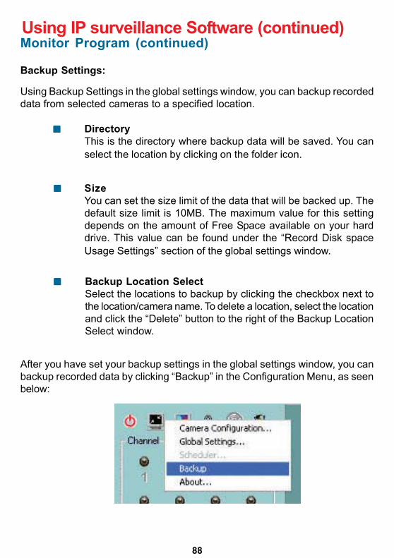
88
Using IP surveillance Software (continued)Monitor Program (continued)
Backup Settings:
Using Backup Settings in the global settings window, you can backup recordeddata from selected cameras to a specified location.
DirectoryThis is the directory where backup data will be saved. You canselect the location by clicking on the folder icon.
SizeYou can set the size limit of the data that will be backed up. Thedefault size limit is 10MB. The maximum value for this settingdepends on the amount of Free Space available on your harddrive. This value can be found under the “Record Disk spaceUsage Settings” section of the global settings window.
Backup Location SelectSelect the locations to backup by clicking the checkbox next tothe location/camera name. To delete a location, select the locationand click the “Delete” button to the right of the Backup LocationSelect window.
After you have set your backup settings in the global settings window, you canbackup recorded data by clicking “Backup” in the Configuration Menu, as seenbelow:
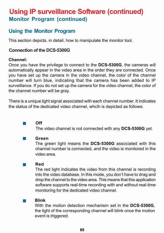
89
Using IP surveillance Software (continued)
This section depicts, in detail, how to manipulate the monitor tool.
Using the Monitor Program
Connection of the DCS-5300G
Channel:Once you have the privilege to connect to the DCS-5300G, the cameras willautomatically appear in the video area in the order they are connected. Onceyou have set up the camera in the video channel, the color of the channelnumber will turn blue, indicating that the camera has been added to IPsurveillance. If you do not set up the camera for the video channel, the color ofthe channel number will be gray.
There is a unique light signal associated with each channel number. It indicatesthe status of the dedicated video channel, whcih is depicted as follows:
OffThe video channel is not connected with any DCS-5300G yet.
GreenThe green light means the DCS-5300G associated with thischannel number is connected, and the video is monitored in thevideo area.
RedThe red light indicates the video from this channel is recordinginto the video database. In this mode, you don’t have to drag anddrop the channel to the video area. This means that this applicationsoftware supports real-time recording with and without real-timemonitoring for the dedicated video channel.
BlinkWith the motion detection mechanism set in the DCS-5300G,the light of the corresponding channel will blink once the motionevent is triggered.
Monitor Program (continued)
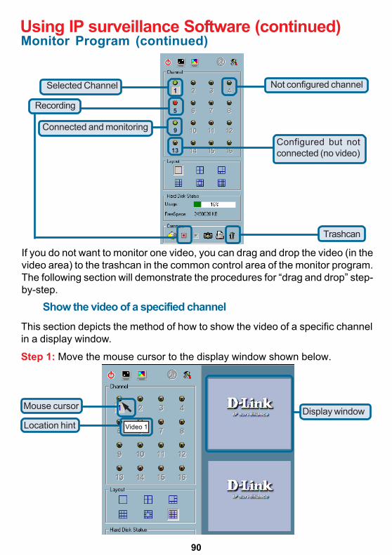
90
Using IP surveillance Software (continued)
If you do not want to monitor one video, you can drag and drop the video (in thevideo area) to the trashcan in the common control area of the monitor program.The following section will demonstrate the procedures for “drag and drop” step-by-step.
Show the video of a specified channelThis section depicts the method of how to show the video of a specific channelin a display window.
Step 1: Move the mouse cursor to the display window shown below.
Video 1
5
9
13
Recording
Selected Channel
Connected and monitoring
Not configured channel
Configured but notconnected (no video)
Trashcan
Mouse cursor
Location hintDisplay window
Monitor Program (continued)
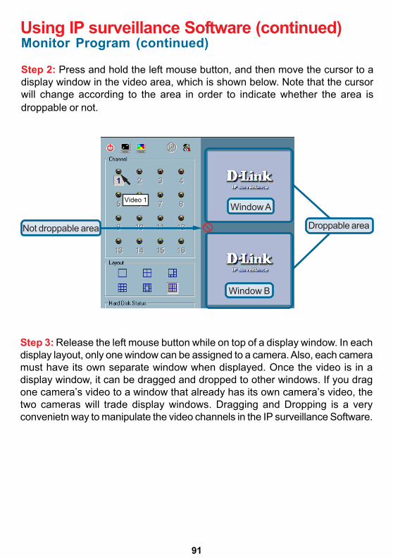
91
Using IP surveillance Software (continued)
Step 2: Press and hold the left mouse button, and then move the cursor to adisplay window in the video area, which is shown below. Note that the cursorwill change according to the area in order to indicate whether the area isdroppable or not.
Video 1
Droppable areaNot droppable area
Step 3: Release the left mouse button while on top of a display window. In eachdisplay layout, only one window can be assigned to a camera. Also, each cameramust have its own separate window when displayed. Once the video is in adisplay window, it can be dragged and dropped to other windows. If you dragone camera’s video to a window that already has its own camera’s video, thetwo cameras will trade display windows. Dragging and Dropping is a veryconvenietn way to manipulate the video channels in the IP surveillance Software.
Monitor Program (continued)
Window A
Window B
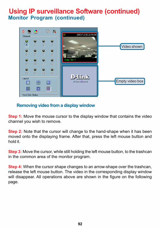
92
Using IP surveillance Software (continued)
Video shown
Empty video box
Removing video from a display window
Step 1: Move the mouse cursor to the display window that contains the videochannel you wish to remove.
Step 2: Note that the cursor will change to the hand-shape when it has beenmoved onto the displaying frame. After that, press the left mouse button andhold it.
Step 3: Move the cursor, while still holding the left mouse button, to the trashcanin the common area of the monitor program.
Step 4: When the cursor shape changes to an arrow-shape over the trashcan,release the left mouse button. The video in the corresponding display windowwill disappear. All operations above are shown in the figure on the followingpage.
Monitor Program (continued)
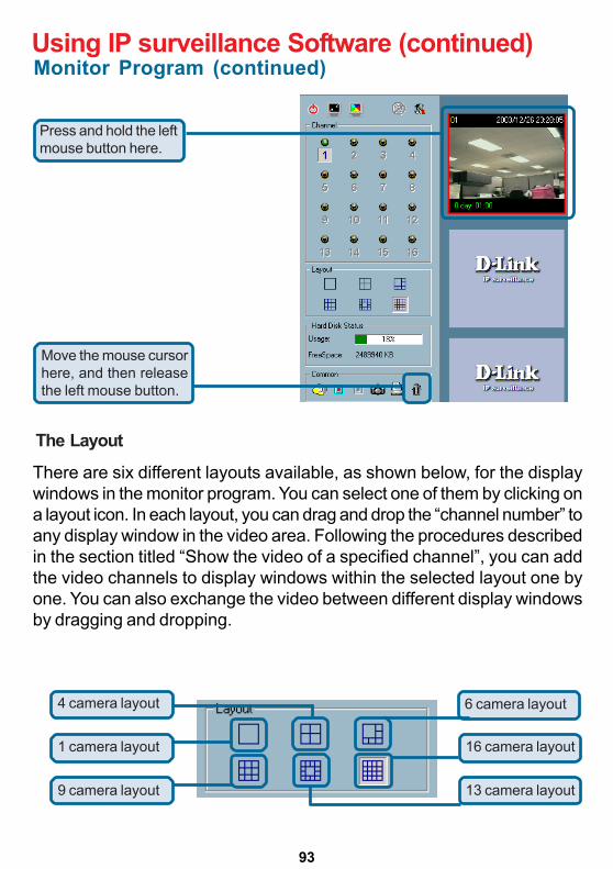
93
Using IP surveillance Software (continued)
Press and hold the leftmouse button here.
Move the mouse cursorhere, and then releasethe left mouse button.
The Layout
There are six different layouts available, as shown below, for the displaywindows in the monitor program. You can select one of them by clicking ona layout icon. In each layout, you can drag and drop the “channel number” toany display window in the video area. Following the procedures describedin the section titled “Show the video of a specified channel”, you can addthe video channels to display windows within the selected layout one byone. You can also exchange the video between different display windowsby dragging and dropping.
4 camera layout
9 camera layout
1 camera layout
6 camera layout
13 camera layout
16 camera layout
Monitor Program (continued)
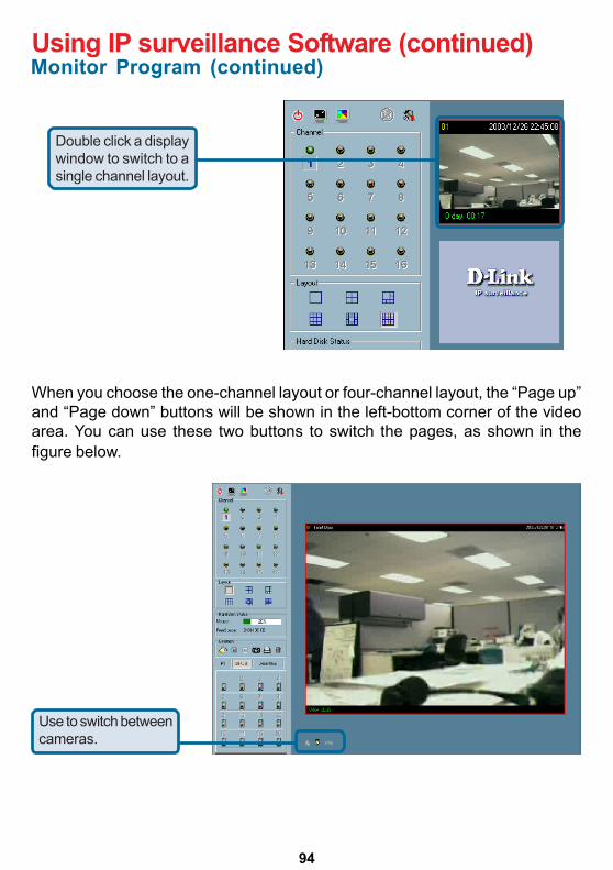
94
Using IP surveillance Software (continued)
Double click a displaywindow to switch to asingle channel layout.
When you choose the one-channel layout or four-channel layout, the “Page up”and “Page down” buttons will be shown in the left-bottom corner of the videoarea. You can use these two buttons to switch the pages, as shown in thefigure below.
Use to switch betweencameras.
Monitor Program (continued)
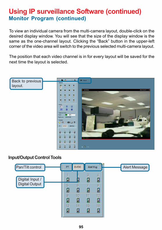
95
Using IP surveillance Software (continued)
To view an individual camera from the multi-camera layout, double-click on thedesired display window. You will see that the size of the display window is thesame as the one-channel layout. Clicking the “Back” button in the upper-leftcorner of the video area will switch to the previous selected multi-camera layout.
The position that each video channel is in for every layout will be saved for thenext time the layout is selected.
BackBack to previouslayout.
Monitor Program (continued)
Input/Output Control Tools
Digital Input /Digital Output
Alert MessagePan/Tilt control
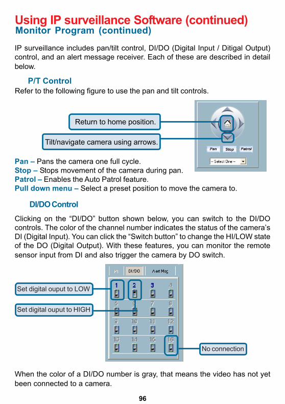
96
Using IP surveillance Software (continued)
IP surveillance includes pan/tilt control, DI/DO (Digital Input / Ditigal Output)control, and an alert message receiver. Each of these are described in detailbelow.
DI/DO ControlClicking on the “DI/DO” button shown below, you can switch to the DI/DOcontrols. The color of the channel number indicates the status of the camera’sDI (Digital Input). You can click the “Switch button” to change the HI/LOW stateof the DO (Digital Output). With these features, you can monitor the remotesensor input from DI and also trigger the camera by DO switch.
Monitor Program (continued)
Set digital ouput to LOW
Set digital ouput to HIGH
No connection
When the color of a DI/DO number is gray, that means the video has not yetbeen connected to a camera.
Refer to the following figure to use the pan and tilt controls.
Pan – Pans the camera one full cycle.Stop – Stops movement of the camera during pan.Patrol – Enables the Auto Patrol feature.Pull down menu – Select a preset position to move the camera to.
Return to home position.
Tilt/navigate camera using arrows.
P/T Control
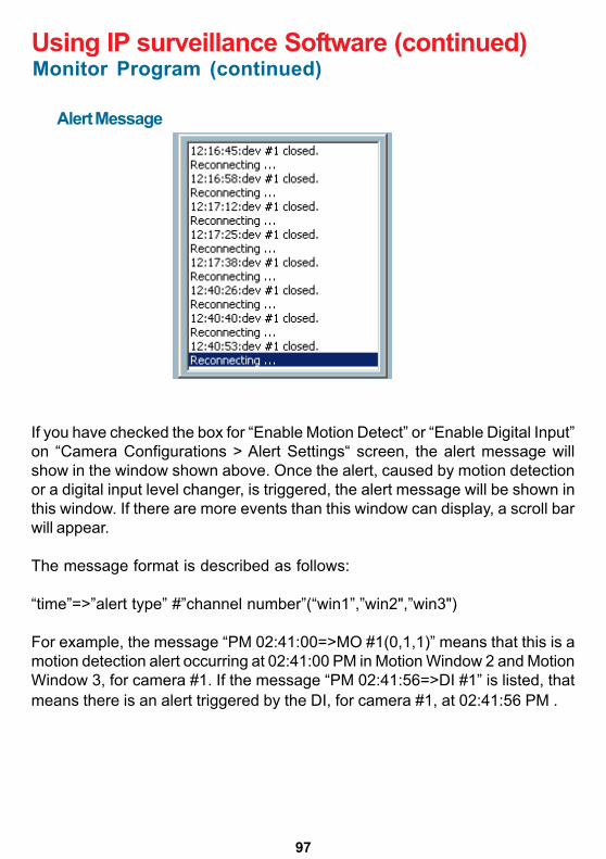
97
Using IP surveillance Software (continued)
Alert Message
If you have checked the box for “Enable Motion Detect” or “Enable Digital Input”on “Camera Configurations > Alert Settings“ screen, the alert message willshow in the window shown above. Once the alert, caused by motion detectionor a digital input level changer, is triggered, the alert message will be shown inthis window. If there are more events than this window can display, a scroll barwill appear.
The message format is described as follows:
“time”=>”alert type” #”channel number”(“win1”,”win2",”win3")
For example, the message “PM 02:41:00=>MO #1(0,1,1)” means that this is amotion detection alert occurring at 02:41:00 PM in Motion Window 2 and MotionWindow 3, for camera #1. If the message “PM 02:41:56=>DI #1” is listed, thatmeans there is an alert triggered by the DI, for camera #1, at 02:41:56 PM .
Monitor Program (continued)
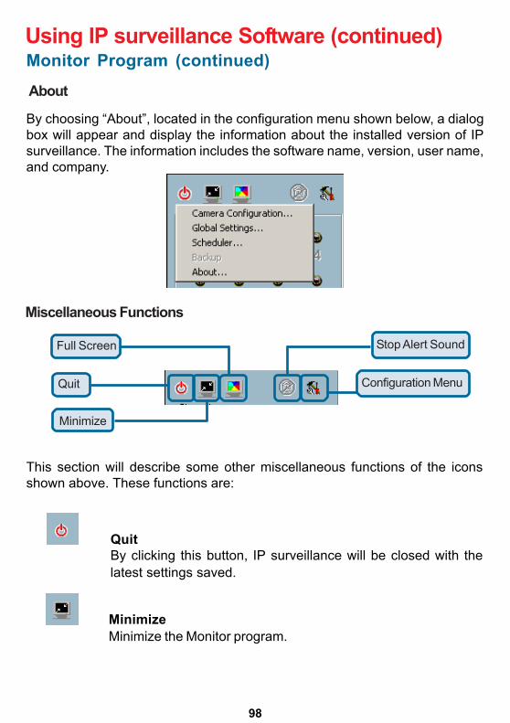
98
Using IP surveillance Software (continued)
About
By choosing “About”, located in the configuration menu shown below, a dialogbox will appear and display the information about the installed version of IPsurveillance. The information includes the software name, version, user name,and company.
Miscellaneous Functions
Full Screen
Quit
Minimize
Stop Alert Sound
Configuration Menu
This section will describe some other miscellaneous functions of the iconsshown above. These functions are:
QuitBy clicking this button, IP surveillance will be closed with thelatest settings saved.
MinimizeMinimize the Monitor program.
Monitor Program (continued)
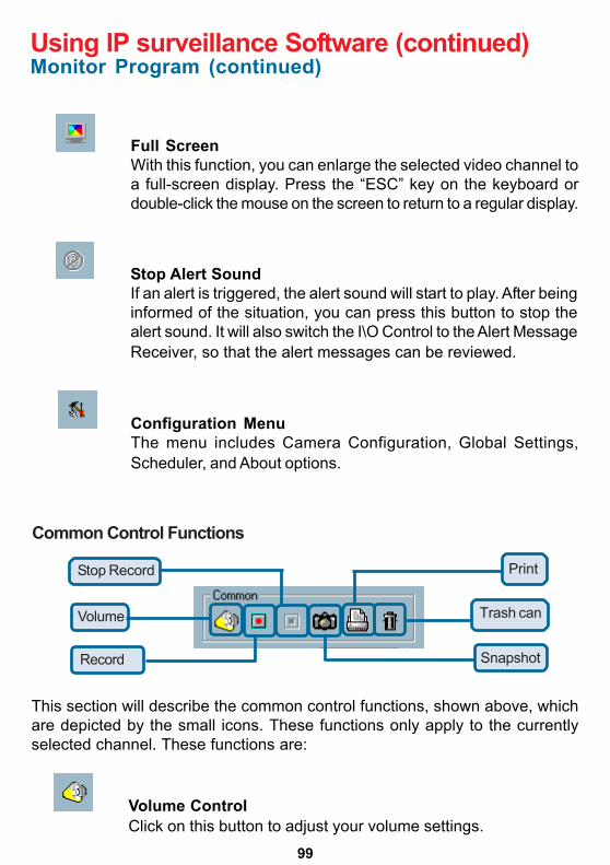
99
Using IP surveillance Software (continued)
Full ScreenWith this function, you can enlarge the selected video channel toa full-screen display. Press the “ESC” key on the keyboard ordouble-click the mouse on the screen to return to a regular display.
Stop Alert SoundIf an alert is triggered, the alert sound will start to play. After beinginformed of the situation, you can press this button to stop thealert sound. It will also switch the I\O Control to the Alert MessageReceiver, so that the alert messages can be reviewed.
Configuration MenuThe menu includes Camera Configuration, Global Settings,Scheduler, and About options.
Common Control Functions
This section will describe the common control functions, shown above, whichare depicted by the small icons. These functions only apply to the currentlyselected channel. These functions are:
Stop Record
Volume
Trash can
Record Snapshot
Volume ControlClick on this button to adjust your volume settings.
Monitor Program (continued)
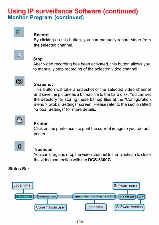
100
Using IP surveillance Software (continued)
RecordBy clicking on this button, you can manually record video fromthe selected channel.
StopAfter video recording has been activated, this button allows youto manually stop recording of the selected video channel.
SnapshotThis button will take a snapshot of the selected video channeland save the picture as a bitmap file to the hard disk. You can setthe directory for storing these bitmap files at the “Configurationmenu > Global Settings” screen. Please refer to the section titled“Global Settings” for more details.
PrinterClick on the printer icon to print the current image to your defaultprinter.
TrashcanYou can drag and drop the video channel to the Trashcan to closethe video connection with the DCS-5300G.
Status Bar
Local time
Current login user Login time Software version
Software name
Monitor Program (continued)
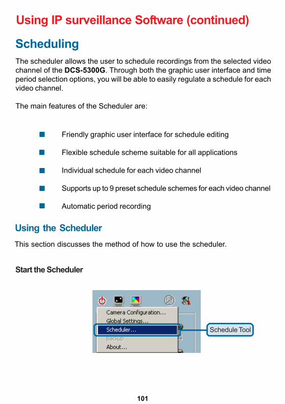
101
Using IP surveillance Software (continued)
Schedule Tool
SchedulingThe scheduler allows the user to schedule recordings from the selected videochannel of the DCS-5300G. Through both the graphic user interface and timeperiod selection options, you will be able to easily regulate a schedule for eachvideo channel.
The main features of the Scheduler are:
Friendly graphic user interface for schedule editing
Flexible schedule scheme suitable for all applications
Individual schedule for each video channel
Supports up to 9 preset schedule schemes for each video channel
Automatic period recording
Using the SchedulerThis section discusses the method of how to use the scheduler.
Start the Scheduler
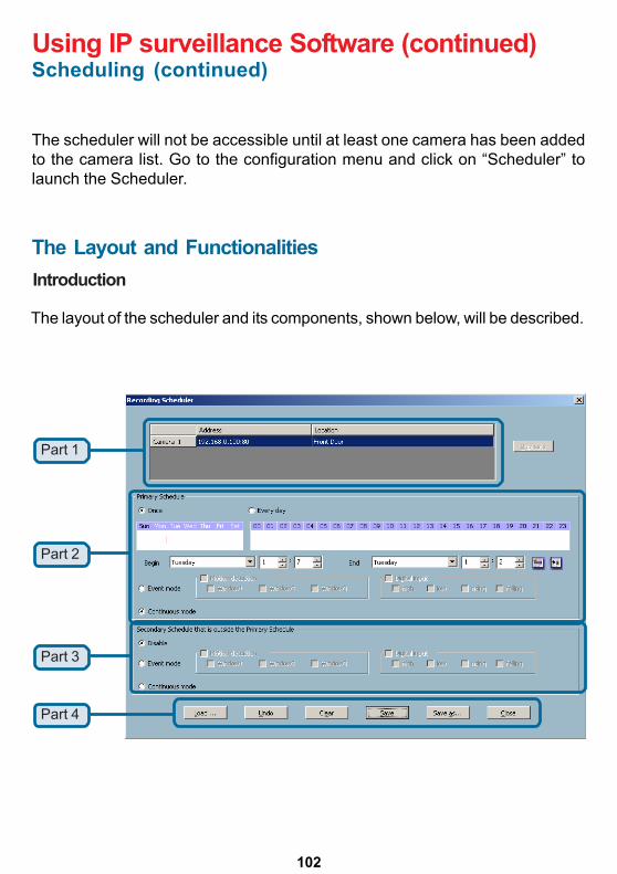
102
Using IP surveillance Software (continued)
Part 1
Part 2
Part 3
Part 4
Scheduling (continued)
The scheduler will not be accessible until at least one camera has been addedto the camera list. Go to the configuration menu and click on “Scheduler” tolaunch the Scheduler.
The Layout and FunctionalitiesIntroduction
The layout of the scheduler and its components, shown below, will be described.
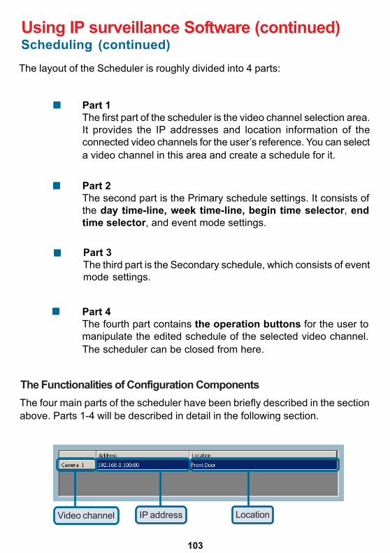
103
Using IP surveillance Software (continued)
Video channel IP address Location
Scheduling (continued)
The layout of the Scheduler is roughly divided into 4 parts:
Part 1The first part of the scheduler is the video channel selection area.It provides the IP addresses and location information of theconnected video channels for the user’s reference. You can selecta video channel in this area and create a schedule for it.
Part 2The second part is the Primary schedule settings. It consists ofthe day time-line, week time-line, begin time selector, endtime selector, and event mode settings.
Part 3The third part is the Secondary schedule, which consists of eventmode settings.
Part 4The fourth part contains the operation buttons for the user tomanipulate the edited schedule of the selected video channel.The scheduler can be closed from here.
The Functionalities of Configuration ComponentsThe four main parts of the scheduler have been briefly described in the sectionabove. Parts 1-4 will be described in detail in the following section.
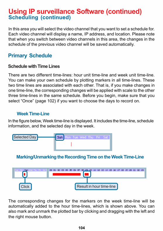
104
Using IP surveillance Software (continued)Scheduling (continued)
In this area you will select the video channel that you want to set a schedule for.Each video channel will display a name, IP address, and location. Please notethat when you switch between video channels in this area, the changes in theschedule of the previous video channel will be saved automatically.
Primary Schedule
Schedule with Time Lines
Week Time-LineIn the figure below, Week time-line is displayed. It includes the time-line, scheduleinformation, and the selected day in the week.
Selected Day
Marking/Unmarking the Recording Time on the Week Time-Line
Click Result in hour time-line
There are two different time-lines: hour unit time-line and week unit time-line.You can make your own schedule by plotting markers in all time-lines. Thesetwo time lines are associated with each other. That is, if you make changes inone time-line, the corresponding changes will be applied with scale to the otherthree time-lines in the same schedule. Before you begin, make sure that youselect “Once” (page 102) if you want to choose the days to record on.
The corresponding changes for the markers on the week time-line will beautomatically added to the hour time-lines, which is shown above. You canalso mark and unmark the plotted bar by clicking and dragging with the left andthe right mouse button.
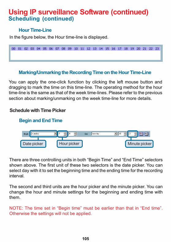
105
Using IP surveillance Software (continued)Scheduling (continued)
Hour Time-LineIn the figure below, the Hour time-line is displayed.
Marking/Unmarking the Recording Time on the Hour Time-Line
You can apply the one-click function by clicking the left mouse button anddragging to mark the time on this time-line. The operating method for the hourtime-line is the same as that of the week time-lines. Please refer to the previoussection about marking/unmarking on the week time-line for more details.
Schedule with Time Picker
Begin and End Time
Date picker Hour picker Minute picker
There are three controlling units in both “Begin Time” and “End Time” selectorsshown above. The first unit of these two selectors is the date picker. You canselect day with it to set the beginning time and the ending time for the recordinginterval.
The second and third units are the hour picker and the minute picker. You canchange the hour and minute settings for the beginning and ending time withthem.
NOTE: The time set in “Begin time” must be earlier than that in “End time”.Otherwise the settings will not be applied.
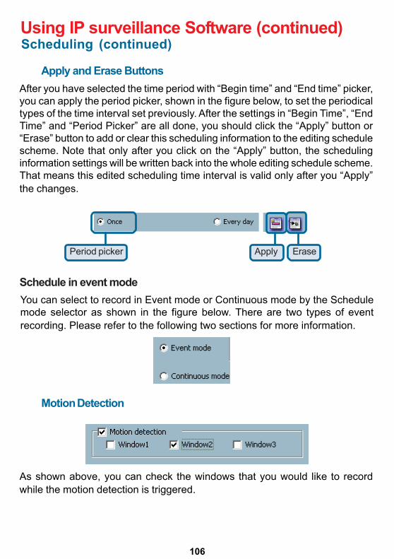
106
Using IP surveillance Software (continued)Scheduling (continued)
Apply and Erase ButtonsAfter you have selected the time period with “Begin time” and “End time” picker,you can apply the period picker, shown in the figure below, to set the periodicaltypes of the time interval set previously. After the settings in “Begin Time”, “EndTime” and “Period Picker” are all done, you should click the “Apply” button or“Erase” button to add or clear this scheduling information to the editing schedulescheme. Note that only after you click on the “Apply” button, the schedulinginformation settings will be written back into the whole editing schedule scheme.That means this edited scheduling time interval is valid only after you “Apply”the changes.
Period picker Apply Erase
Schedule in event modeYou can select to record in Event mode or Continuous mode by the Schedulemode selector as shown in the figure below. There are two types of eventrecording. Please refer to the following two sections for more information.
Motion Detection
As shown above, you can check the windows that you would like to recordwhile the motion detection is triggered.
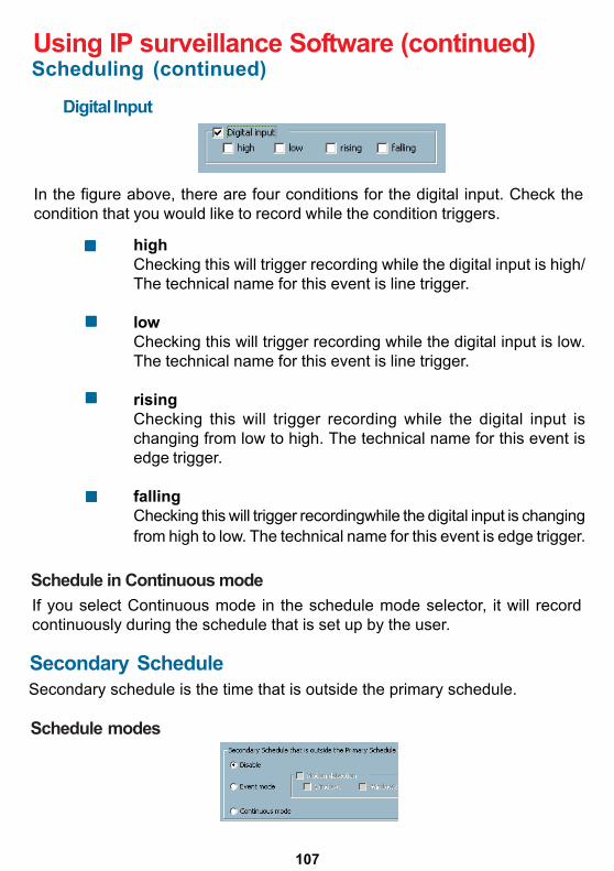
107
Using IP surveillance Software (continued)Scheduling (continued)
Digital Input
In the figure above, there are four conditions for the digital input. Check thecondition that you would like to record while the condition triggers.
highChecking this will trigger recording while the digital input is high/The technical name for this event is line trigger.
lowChecking this will trigger recording while the digital input is low.The technical name for this event is line trigger.
risingChecking this will trigger recording while the digital input ischanging from low to high. The technical name for this event isedge trigger.
fallingChecking this will trigger recordingwhile the digital input is changingfrom high to low. The technical name for this event is edge trigger.
Schedule modes
If you select Continuous mode in the schedule mode selector, it will recordcontinuously during the schedule that is set up by the user.
Secondary ScheduleSecondary schedule is the time that is outside the primary schedule.
Schedule in Continuous mode
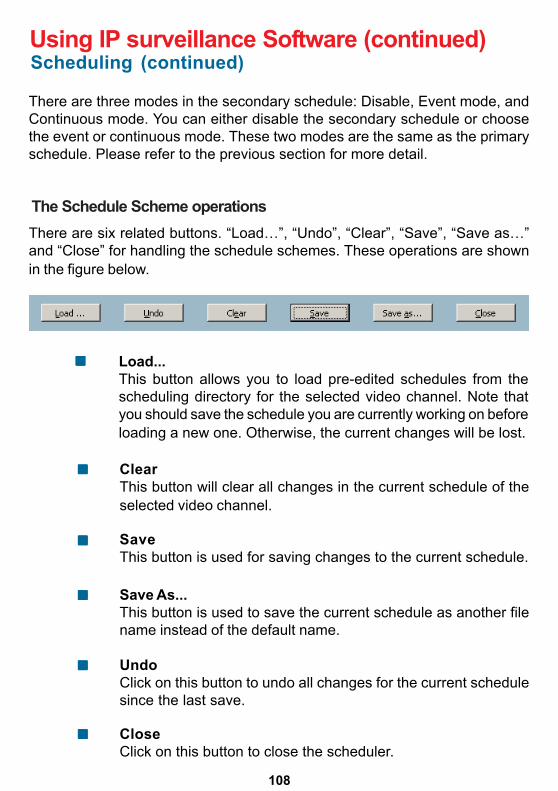
108
Using IP surveillance Software (continued)Scheduling (continued)
The Schedule Scheme operationsThere are six related buttons. “Load…”, “Undo”, “Clear”, “Save”, “Save as…”and “Close” for handling the schedule schemes. These operations are shownin the figure below.
There are three modes in the secondary schedule: Disable, Event mode, andContinuous mode. You can either disable the secondary schedule or choosethe event or continuous mode. These two modes are the same as the primaryschedule. Please refer to the previous section for more detail.
UndoClick on this button to undo all changes for the current schedulesince the last save.
CloseClick on this button to close the scheduler.
Load...This button allows you to load pre-edited schedules from thescheduling directory for the selected video channel. Note thatyou should save the schedule you are currently working on beforeloading a new one. Otherwise, the current changes will be lost.
ClearThis button will clear all changes in the current schedule of theselected video channel.
SaveThis button is used for saving changes to the current schedule.
Save As...This button is used to save the current schedule as another filename instead of the default name.
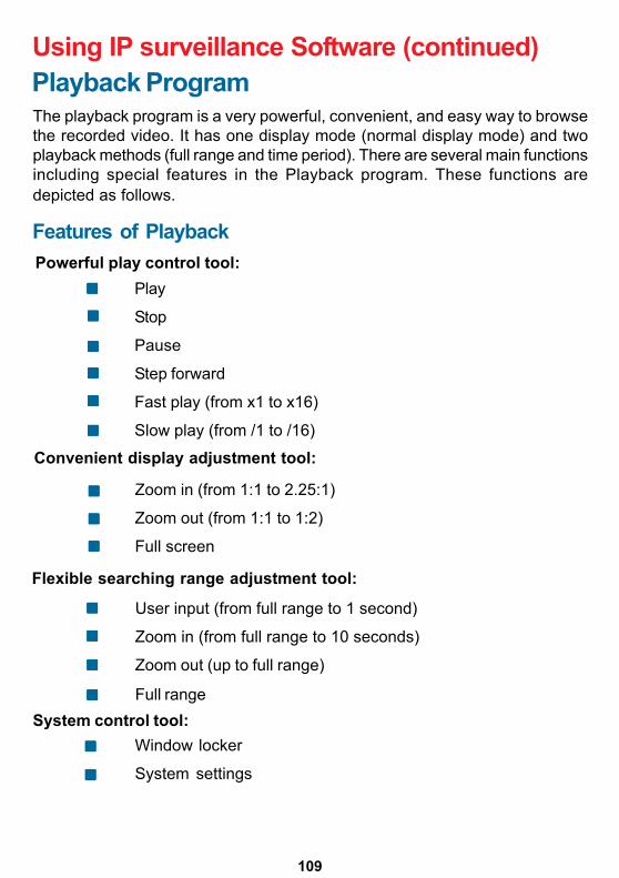
109
Using IP surveillance Software (continued)Playback ProgramThe playback program is a very powerful, convenient, and easy way to browsethe recorded video. It has one display mode (normal display mode) and twoplayback methods (full range and time period). There are several main functionsincluding special features in the Playback program. These functions aredepicted as follows.
Powerful play control tool:Play
Stop
Pause
Step forward
Fast play (from x1 to x16)
Slow play (from /1 to /16)
Convenient display adjustment tool:
Zoom in (from 1:1 to 2.25:1)
Zoom out (from 1:1 to 1:2)
Full screen
Flexible searching range adjustment tool:
User input (from full range to 1 second)
Zoom in (from full range to 10 seconds)
Zoom out (up to full range)
Full rangeSystem control tool:
Window locker
System settings
Features of Playback
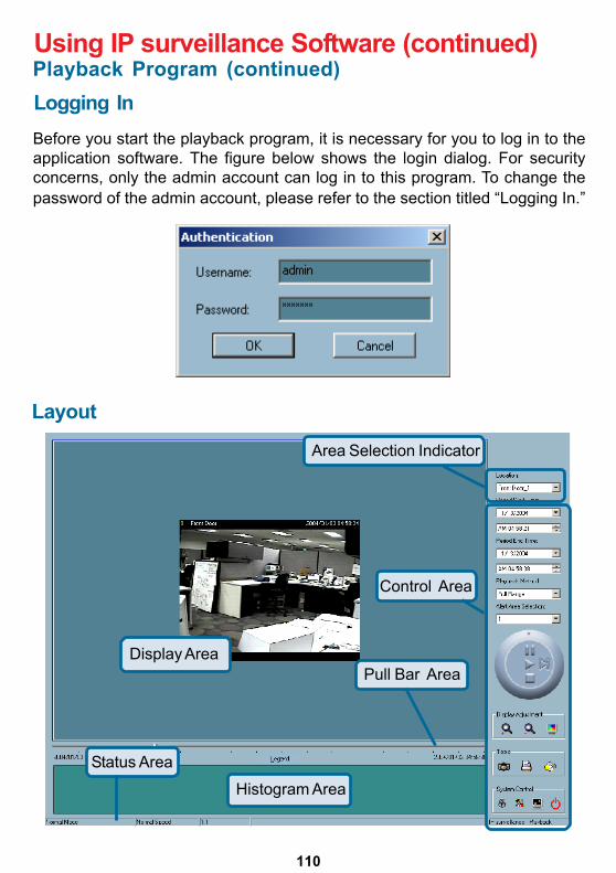
110
Using IP surveillance Software (continued)
Logging InBefore you start the playback program, it is necessary for you to log in to theapplication software. The figure below shows the login dialog. For securityconcerns, only the admin account can log in to this program. To change thepassword of the admin account, please refer to the section titled “Logging In.”
Layout
Display Area
Control Area
Pull Bar Area
Area Selection Indicator
Status Area
Histogram Area
Playback Program (continued)
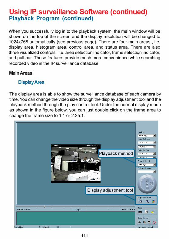
111
Using IP surveillance Software (continued)Playback Program (continued)
When you successfully log in to the playback system, the main window will beshown on the top of the screen and the display resolution will be changed to1024x768 automatically (see previous page). There are four main areas , i.e.display area, histogram area, control area, and status area. There are alsothree visualized controls , i.e. area selection indicator, frame selection indicator,and pull bar. These features provide much more convenience while searchingrecorded video in the IP surveillance database.
Main Areas
Display Area
The display area is able to show the surveillance database of each camera bytime. You can change the video size through the display adjustment tool and theplayback method through the play control tool. Under the normal display modeas shown in the figure below, you can just double click on the frame area tochange the frame size to 1:1 or 2.25:1.
Playback method
Display adjustment tool
112
Using IP surveillance Software (continued)Playback Program (continued)
Histogram Area
The histogram is an interactive control. Not only can you get the event’s locationin time domain and its quantity of the motion percentage, but you can also selecta group of events or a period from the event histogram area and show it on thedisplay area.
Control Area
The control area contains almost all the control selectors and toolboxes youneed to browse the database. These control tools include location selector,period selector, playback method selector, jog dial, display adjustment tool,searching range adjustment tool, exporting tool, and system control tool. Thesetools are discussed in more detail in the section titled “Using Tools.”
Status Area
The status area is located at the bottom of the main window. It tells you theprogram status information including display mode, display size, display speed,exporting file format, and exporting file name.
Indicators
Area Selection Indicator
In the main playback window, the display area is surrounded by a blue rectangle.This rectangle is the area selection indicator. This indicator can be set to eitherdisplay area or histogram area, as long as you move your mouse cursor to thearea you intend to select. When you select the display area, the displayadjustment tool will appear in the control area. If you select the histogram area,the display adjustment tool will disappear and the searching range adjustmenttool will be shown in the same place of the control area.
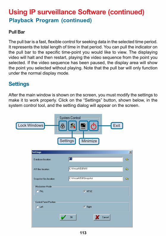
113
Using IP surveillance Software (continued)Playback Program (continued)
Pull Bar
The pull bar is a fast, flexible control for seeking data in the selected time period.It represents the total length of time in that period. You can pull the indicator onthe pull bar to the specific time-point you would like to view. The displayingvideo will halt and then restart, playing the video sequence from the point youselected. If the video sequence has been paused, the display area will showthe point you selected without playing. Note that the pull bar will only functionunder the normal display mode.
Settings
After the main window is shown on the screen, you must modify the settings tomake it to work properly. Click on the “Settings” button, shown below, in thesystem control tool, and the setting dialog will appear on the screen.
Lock Windows
Settings Minimize
Exit
114
Playback Program (continued)Using IP surveillance Software (continued)
Database locationThe most important item in the settings dialog is the databaselocation setting. You must set it to the directory that contains thesurveillance database to make the program to work properly.
The items in the settings windows are:
Modulation Mode:The modulation mode cannot be changed. This depends on howyou recorded the video sequence in the monitor program. If youselect the wrong mode, the video shown in the display area willbecome distorted. If you have chosen the wrong modulationmode, you may open the settings dialog again, change to thecorrect mode, and restart the playback program. The display willnow be normal.
AVI file locationThis sets the directory where exported AVI files will be stored.Exported AVI files will be stored in the sub-directory (cameraname) under the directory you set here.
Snapshot file locationThis sets the directory where bitmap files will be stored whenyou use the snapshot to export them. Exporting bitmap files willbe stored in the sub-directory (camera name) under the directoryyou set here.
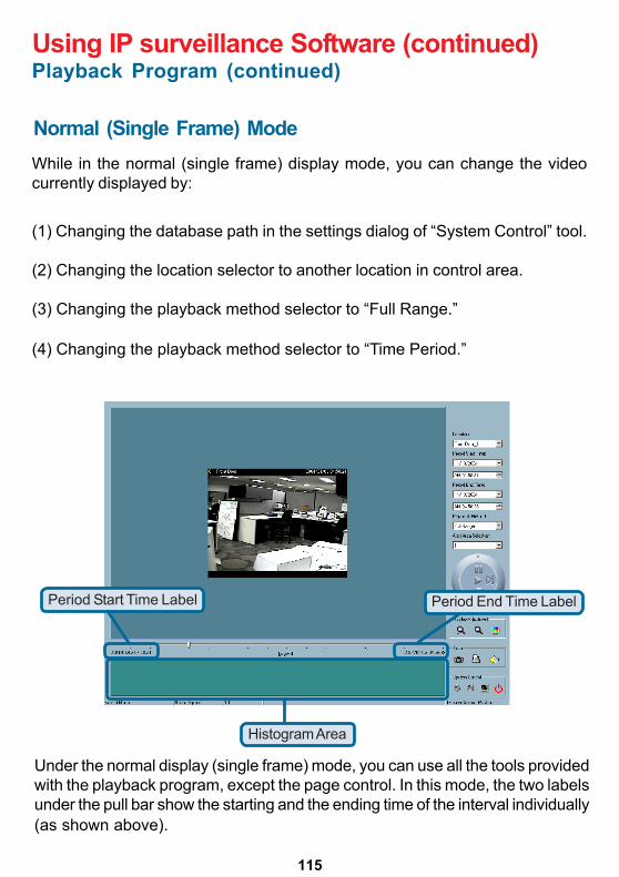
115
Playback Program (continued)Using IP surveillance Software (continued)
Normal (Single Frame) Mode
Period Start Time Label Period End Time Label
Histogram Area
Under the normal display (single frame) mode, you can use all the tools providedwith the playback program, except the page control. In this mode, the two labelsunder the pull bar show the starting and the ending time of the interval individually(as shown above).
(1) Changing the database path in the settings dialog of “System Control” tool.
(2) Changing the location selector to another location in control area.
(3) Changing the playback method selector to “Full Range.”
(4) Changing the playback method selector to “Time Period.”
While in the normal (single frame) display mode, you can change the videocurrently displayed by:
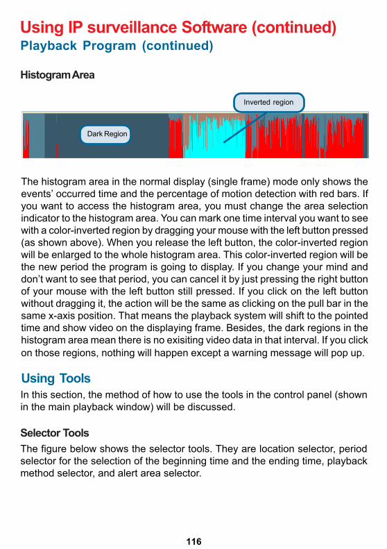
116
Playback Program (continued)Using IP surveillance Software (continued)
Histogram Area
The histogram area in the normal display (single frame) mode only shows theevents’ occurred time and the percentage of motion detection with red bars. Ifyou want to access the histogram area, you must change the area selectionindicator to the histogram area. You can mark one time interval you want to seewith a color-inverted region by dragging your mouse with the left button pressed(as shown above). When you release the left button, the color-inverted regionwill be enlarged to the whole histogram area. This color-inverted region will bethe new period the program is going to display. If you change your mind anddon’t want to see that period, you can cancel it by just pressing the right buttonof your mouse with the left button still pressed. If you click on the left buttonwithout dragging it, the action will be the same as clicking on the pull bar in thesame x-axis position. That means the playback system will shift to the pointedtime and show video on the displaying frame. Besides, the dark regions in thehistogram area mean there is no exisiting video data in that interval. If you clickon those regions, nothing will happen except a warning message will pop up.
Using ToolsIn this section, the method of how to use the tools in the control panel (shownin the main playback window) will be discussed.
Selector ToolsThe figure below shows the selector tools. They are location selector, periodselector for the selection of the beginning time and the ending time, playbackmethod selector, and alert area selector.
Dark Region
Inverted region
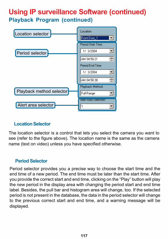
117
Playback Program (continued)Using IP surveillance Software (continued)
Location selector
Period selector
Playback method selector
Alert area selector
Location Selector
The location selector is a control that lets you select the camera you want tosee (refer to the figure above). The location name is the same as the cameraname (text on video) unless you have specified otherwise.
Period SelectorPeriod selector provides you a precise way to choose the start time and theend time of a new period. The end time must be later than the start time. Afteryou provide the correct start and end time, clicking on the “Play” button will playthe new period in the display area with changing the period start and end timelabel. Besides, the pull bar and histogram area will change, too. If the selectedperiod is not present in the database, the data in the period selector will changeto the previous correct start and end time, and a warning message will bedisplayed.
118
Playback Program (continued)Using IP surveillance Software (continued)
Playback Method Selector
Full RangeIf you select this method, the database will be displayed from thebeginning to the end of this location. Any change in the periodselector will have no effect except when you change this selectorto “Time Period.”
Time PeriodIf you change the playback method to “Time Period”, you canmodify the start and end time in the period selector. When youclick on the “Play” button in the jog dial, the period you selectedwill be displayed.
Since the program will record the previous start and end time in “Time Period”and “Events Preview” mode, whenever you want to change the period selectorto see the other periods, you must change the playback method selector to themode you want to use first. Otherwise, the period selector will revert back tothe previous period set the last time you changed the playback method selector.
Alert Area Selector
In the preview mode, the playback program can show the information of totalevents of only one alert window each time. If you want to see the events of theother two alert area windows, you must change the alert area selector to theother window numbers. In the normal display mode, the alert window that thealert area selector indicates will be highlighted with red rectangle if you checkedthat window in the settings dialog. The alert area selector will be changed toalert window 0 by default settings when you change the location selector toanother window.
Play ControlFor the play control, the jog dial, shown in the figure below, is used to providethe easiest method of controlling the video sequence display. All buttons cancontrol the displaying frame in the normal display mode.
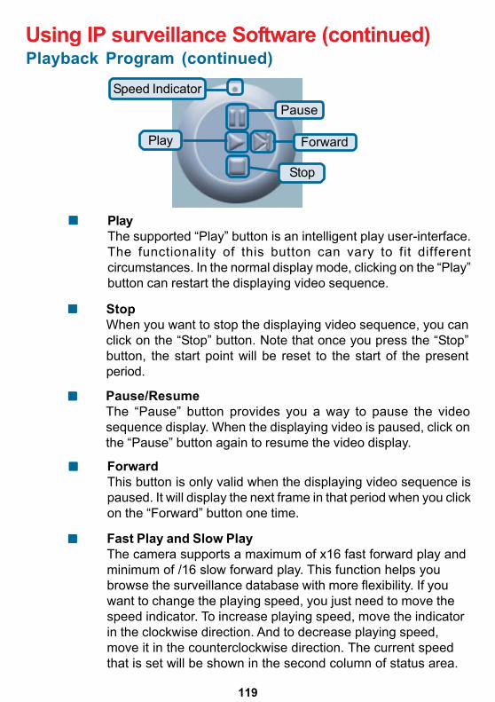
119
Playback Program (continued)Using IP surveillance Software (continued)
PlayThe supported “Play” button is an intelligent play user-interface.The functionality of this button can vary to fit differentcircumstances. In the normal display mode, clicking on the “Play”button can restart the displaying video sequence.
ForwardThis button is only valid when the displaying video sequence ispaused. It will display the next frame in that period when you clickon the “Forward” button one time.
Speed Indicator
ForwardPlay
Stop
Pause
StopWhen you want to stop the displaying video sequence, you canclick on the “Stop” button. Note that once you press the “Stop”button, the start point will be reset to the start of the presentperiod.
Pause/ResumeThe “Pause” button provides you a way to pause the videosequence display. When the displaying video is paused, click onthe “Pause” button again to resume the video display.
Fast Play and Slow PlayThe camera supports a maximum of x16 fast forward play andminimum of /16 slow forward play. This function helps youbrowse the surveillance database with more flexibility. If youwant to change the playing speed, you just need to move thespeed indicator. To increase playing speed, move the indicatorin the clockwise direction. And to decrease playing speed,move it in the counterclockwise direction. The current speedthat is set will be shown in the second column of status area.
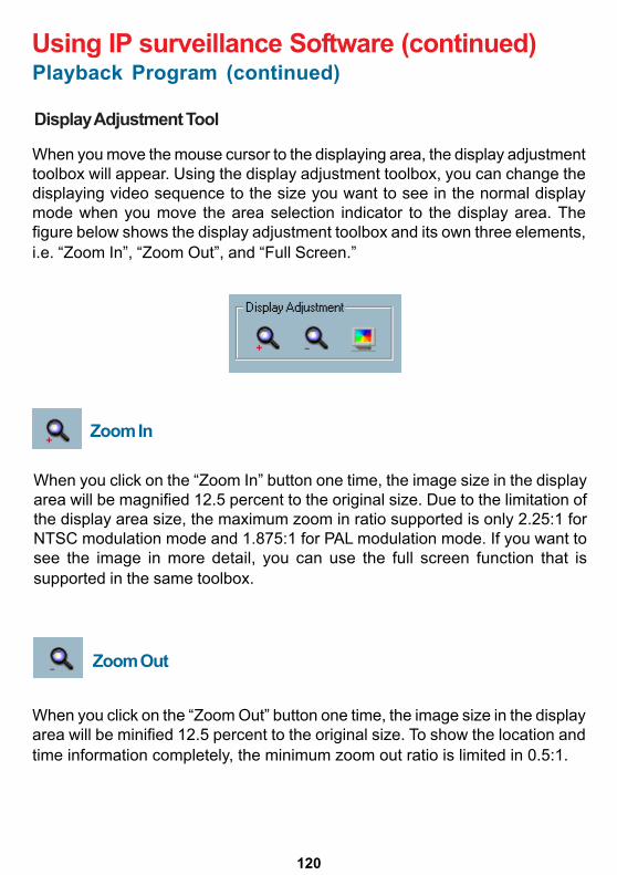
120
Playback Program (continued)Using IP surveillance Software (continued)
Display Adjustment Tool
When you move the mouse cursor to the displaying area, the display adjustmenttoolbox will appear. Using the display adjustment toolbox, you can change thedisplaying video sequence to the size you want to see in the normal displaymode when you move the area selection indicator to the display area. Thefigure below shows the display adjustment toolbox and its own three elements,i.e. “Zoom In”, “Zoom Out”, and “Full Screen.”
Zoom In
When you click on the “Zoom In” button one time, the image size in the displayarea will be magnified 12.5 percent to the original size. Due to the limitation ofthe display area size, the maximum zoom in ratio supported is only 2.25:1 forNTSC modulation mode and 1.875:1 for PAL modulation mode. If you want tosee the image in more detail, you can use the full screen function that issupported in the same toolbox.
When you click on the “Zoom Out” button one time, the image size in the displayarea will be minified 12.5 percent to the original size. To show the location andtime information completely, the minimum zoom out ratio is limited in 0.5:1.
Zoom Out
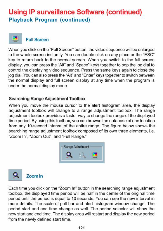
121
Playback Program (continued)Using IP surveillance Software (continued)
Full Screen
When you click on the “Full Screen” button, the video sequence will be enlargedto the whole screen instantly. You can double click on any place or the “ESC”key to return back to the normal screen. When you switch to the full screendisplay, you can press the “Alt” and “Space” keys together to pop the jog dial tocontrol the displaying video sequence. Press the same keys again to close thejog dial. You can also press the “Alt” and “Enter” keys together to switch betweenthe normal display and full screen display at any time when the program isunder the normal display mode.
Searching Range Adjustment ToolboxWhen you move the mouse cursor to the alert histogram area, the displayadjustment toolbox will change to a range adjustment toolbox. The rangeadjustment toolbox provides a faster way to change the range of the displayedtime period. By using this toolbox, you can browse the database of one locationfrom any 10-second interval of the entire range. The figure below shows thesearching range adjustment toolbox composed of its own three elements, i.e.“Zoom In”, “Zoom Out”, and “Full Range.”
Zoom In
Each time you click on the “Zoom In” button in the searching range adjustmenttoolbox, the displayed time period will be half in the center of the original timeperiod until the period is equal to 10 seconds. You can see the new interval inmore details. The scale of pull bar and alert histogram window change. Theperiod start and end time change as well. The period selector will show thenew start and end time. The display area will restart and display the new periodfrom the newly defined start time.
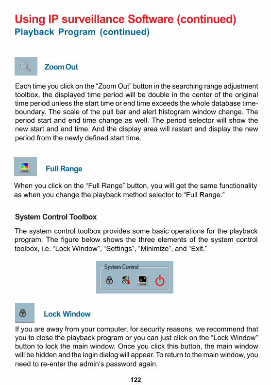
122
Zoom Out
Playback Program (continued)Using IP surveillance Software (continued)
Lock Window
Each time you click on the “Zoom Out” button in the searching range adjustmenttoolbox, the displayed time period will be double in the center of the originaltime period unless the start time or end time exceeds the whole database time-boundary. The scale of the pull bar and alert histogram window change. Theperiod start and end time change as well. The period selector will show thenew start and end time. And the display area will restart and display the newperiod from the newly defined start time.
When you click on the “Full Range” button, you will get the same functionalityas when you change the playback method selector to “Full Range.”
System Control Toolbox
The system control toolbox provides some basic operations for the playbackprogram. The figure below shows the three elements of the system controltoolbox, i.e. “Lock Window”, “Settings”, “Minimize”, and “Exit.”
Full Range
If you are away from your computer, for security reasons, we recommend thatyou to close the playback program or you can just click on the “Lock Window”button to lock the main window. Once you click this button, the main windowwill be hidden and the login dialog will appear. To return to the main window, youneed to re-enter the admin’s password again.
123
Settings
Playback Program (continued)Using IP surveillance Software (continued)
The settings dialog will pop up when you click the “Settings” button. For moreinformation about setting this program, please refer to the section titled"Settings.”
Minimize
Click this button in order to minimize the playback program window.
Exit
The playback program will be closed immediately when you click on the “Exit”button.
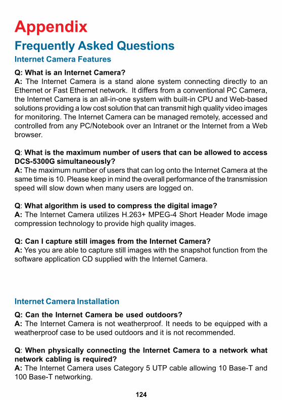
124
AppendixFrequently Asked QuestionsInternet Camera FeaturesQ: What is an Internet Camera?A: The Internet Camera is a stand alone system connecting directly to anEthernet or Fast Ethernet network. It differs from a conventional PC Camera,the Internet Camera is an all-in-one system with built-in CPU and Web-basedsolutions providing a low cost solution that can transmit high quality video imagesfor monitoring. The Internet Camera can be managed remotely, accessed andcontrolled from any PC/Notebook over an Intranet or the Internet from a Webbrowser.
Q: What is the maximum number of users that can be allowed to accessDCS-5300G simultaneously?A: The maximum number of users that can log onto the Internet Camera at thesame time is 10. Please keep in mind the overall performance of the transmissionspeed will slow down when many users are logged on.
Q: What algorithm is used to compress the digital image?A: The Internet Camera utilizes H.263+ MPEG-4 Short Header Mode imagecompression technology to provide high quality images.
Q: Can I capture still images from the Internet Camera?A: Yes you are able to capture still images with the snapshot function from thesoftware application CD supplied with the Internet Camera.
Internet Camera InstallationQ: Can the Internet Camera be used outdoors?A: The Internet Camera is not weatherproof. It needs to be equipped with aweatherproof case to be used outdoors and it is not recommended.
Q: When physically connecting the Internet Camera to a network whatnetwork cabling is required?A: The Internet Camera uses Category 5 UTP cable allowing 10 Base-T and100 Base-T networking.
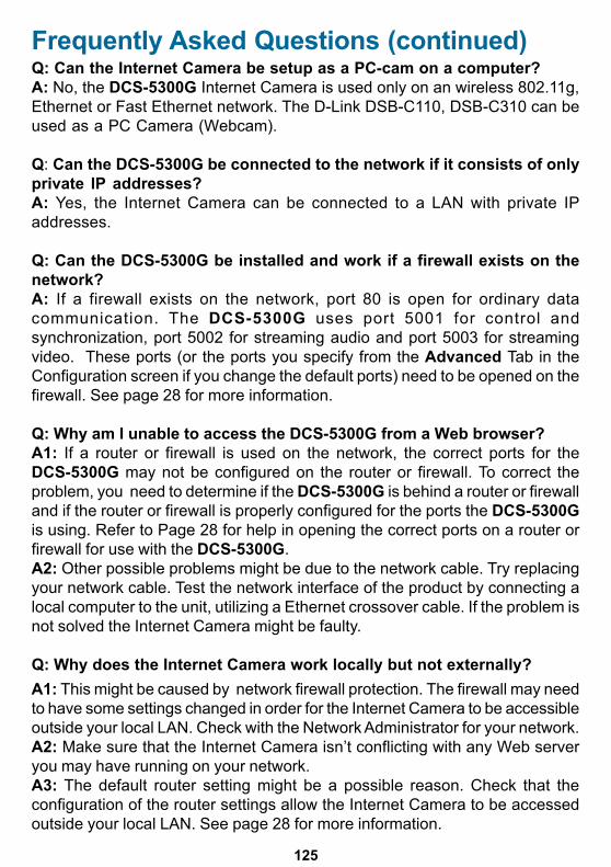
125
Q: Can the Internet Camera be setup as a PC-cam on a computer?A: No, the DCS-5300G Internet Camera is used only on an wireless 802.11g,Ethernet or Fast Ethernet network. The D-Link DSB-C110, DSB-C310 can beused as a PC Camera (Webcam).
Q: Can the DCS-5300G be connected to the network if it consists of onlyprivate IP addresses?A: Yes, the Internet Camera can be connected to a LAN with private IPaddresses.
Q: Can the DCS-5300G be installed and work if a firewall exists on thenetwork?A: If a firewall exists on the network, port 80 is open for ordinary datacommunication. The DCS-5300G uses port 5001 for control andsynchronization, port 5002 for streaming audio and port 5003 for streamingvideo. These ports (or the ports you specify from the Advanced Tab in theConfiguration screen if you change the default ports) need to be opened on thefirewall. See page 28 for more information.
Q: Why am I unable to access the DCS-5300G from a Web browser?A1: If a router or firewall is used on the network, the correct ports for theDCS-5300G may not be configured on the router or firewall. To correct theproblem, you need to determine if the DCS-5300G is behind a router or firewalland if the router or firewall is properly configured for the ports the DCS-5300Gis using. Refer to Page 28 for help in opening the correct ports on a router orfirewall for use with the DCS-5300G.A2: Other possible problems might be due to the network cable. Try replacingyour network cable. Test the network interface of the product by connecting alocal computer to the unit, utilizing a Ethernet crossover cable. If the problem isnot solved the Internet Camera might be faulty.
Q: Why does the Internet Camera work locally but not externally?A1: This might be caused by network firewall protection. The firewall may needto have some settings changed in order for the Internet Camera to be accessibleoutside your local LAN. Check with the Network Administrator for your network.A2: Make sure that the Internet Camera isn’t conflicting with any Web serveryou may have running on your network.A3: The default router setting might be a possible reason. Check that theconfiguration of the router settings allow the Internet Camera to be accessedoutside your local LAN. See page 28 for more information.
Frequently Asked Questions (continued)
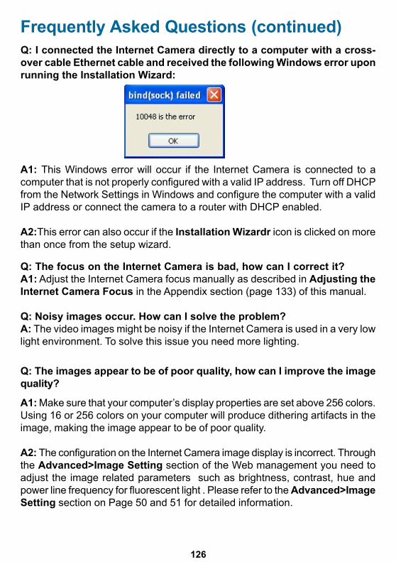
126
Q: The focus on the Internet Camera is bad, how can I correct it?A1: Adjust the Internet Camera focus manually as described in Adjusting theInternet Camera Focus in the Appendix section (page 133) of this manual.
Q: Noisy images occur. How can I solve the problem?A: The video images might be noisy if the Internet Camera is used in a very lowlight environment. To solve this issue you need more lighting.
Frequently Asked Questions (continued)Q: I connected the Internet Camera directly to a computer with a cross-over cable Ethernet cable and received the following Windows error uponrunning the Installation Wizard:
A1: This Windows error will occur if the Internet Camera is connected to acomputer that is not properly configured with a valid IP address. Turn off DHCPfrom the Network Settings in Windows and configure the computer with a validIP address or connect the camera to a router with DHCP enabled.
A2:This error can also occur if the Installation Wizardr icon is clicked on morethan once from the setup wizard.
Q: The images appear to be of poor quality, how can I improve the imagequality?
A1: Make sure that your computer’s display properties are set above 256 colors.Using 16 or 256 colors on your computer will produce dithering artifacts in theimage, making the image appear to be of poor quality.
A2: The configuration on the Internet Camera image display is incorrect. Throughthe Advanced>Image Setting section of the Web management you need toadjust the image related parameters such as brightness, contrast, hue andpower line frequency for fluorescent light . Please refer to the Advanced>ImageSetting section on Page 50 and 51 for detailed information.
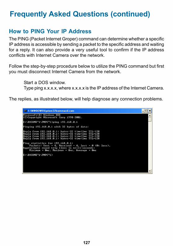
127
How to PING Your IP AddressThe PING (Packet Internet Groper) command can determine whether a specificIP address is accessible by sending a packet to the specific address and waitingfor a reply. It can also provide a very useful tool to confirm if the IP addressconflicts with Internet Camera over the network.
Follow the step-by-step procedure below to utilize the PING command but firstyou must disconnect Internet Camera from the network.
Start a DOS window.Type ping x.x.x.x, where x.x.x.x is the IP address of the Internet Camera.
The replies, as illustrated below, will help diagnose any connection problems.
Frequently Asked Questions (continued)
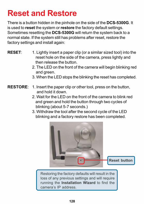
128
There is a button hidden in the pinhole on the side of the DCS-5300G. Itis used to reset the system or restore the factory default settings.Sometimes resetting the DCS-5300G will return the system back to anormal state. If the system still has problems after reset, restore thefactory settings and install again:
RESET: 1. Lightly insert a paper clip (or a similar sized tool) into the reset hole on the side of the camera, press lightly and then release the button.2. The LED on the front of the camera will begin blinking red and green.3. When the LED stops the blinking the reset has completed.
RESTORE: 1. Insert the paper clip or other tool, press on the button, and hold it down.2. Wait for the LED on the front of the camera to blink red and green and hold the button through two cycles of blinking (about 5-7 seconds.)3. Withdraw the tool after the second cycle of the LED blinking and a factory restore has been completed.
Reset and Restore
Restoring the factory defaults will result in theloss of any previous settings and will requirerunning the Installation Wizard to find thecamera’s IP address.
Reset button
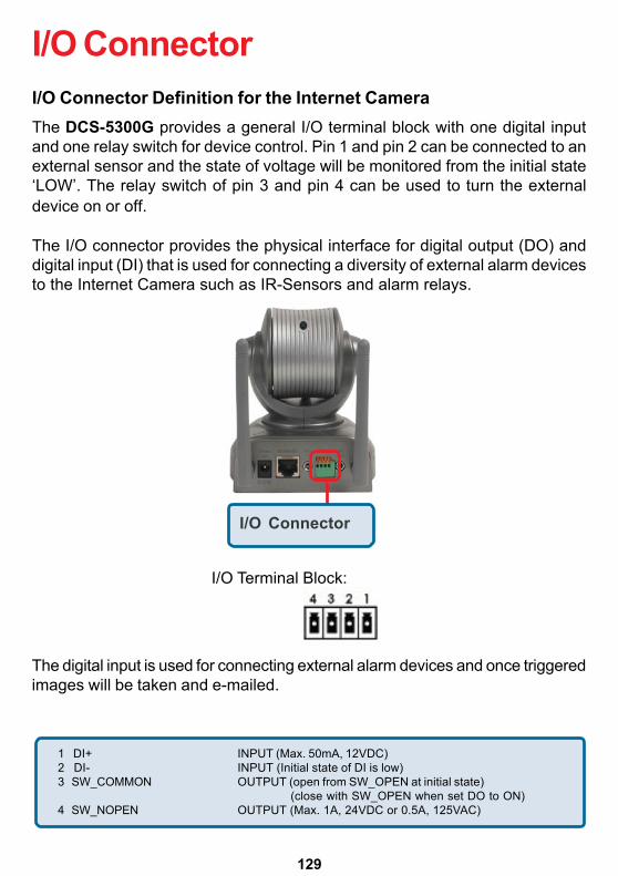
129
I/O Connector Definition for the Internet CameraThe DCS-5300G provides a general I/O terminal block with one digital inputand one relay switch for device control. Pin 1 and pin 2 can be connected to anexternal sensor and the state of voltage will be monitored from the initial state‘LOW’. The relay switch of pin 3 and pin 4 can be used to turn the externaldevice on or off.
The I/O connector provides the physical interface for digital output (DO) anddigital input (DI) that is used for connecting a diversity of external alarm devicesto the Internet Camera such as IR-Sensors and alarm relays.
I/O Connector
The digital input is used for connecting external alarm devices and once triggeredimages will be taken and e-mailed.
1 DI+ INPUT (Max. 50mA, 12VDC)2 DI- INPUT (Initial state of DI is low)3 SW_COMMON OUTPUT (open from SW_OPEN at initial state)
(close with SW_OPEN when set DO to ON)4 SW_NOPEN OUTPUT (Max. 1A, 24VDC or 0.5A, 125VAC)
I/O Terminal Block:
I/O Connector
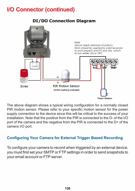
130
The above diagram shows a typical wiring configuration for a normally closedPIR motion sensor. Please refer to your specific motion sensor for the powersupply connection to the device since this will be critical to the success of yourinstallation. Note that the positive from the PIR is connected to the D- of the I/Oport of the camera and the negative from the PIR is connected to the D+ of thecamera I/O port.
Configuring Your Camera for External Trigger Based Recording
I/O Connector (continued)
To configure your camera to record when triggered by an external device,you must first set your SMTP or FTP settings in order to send snapshots toyour email account or FTP server.
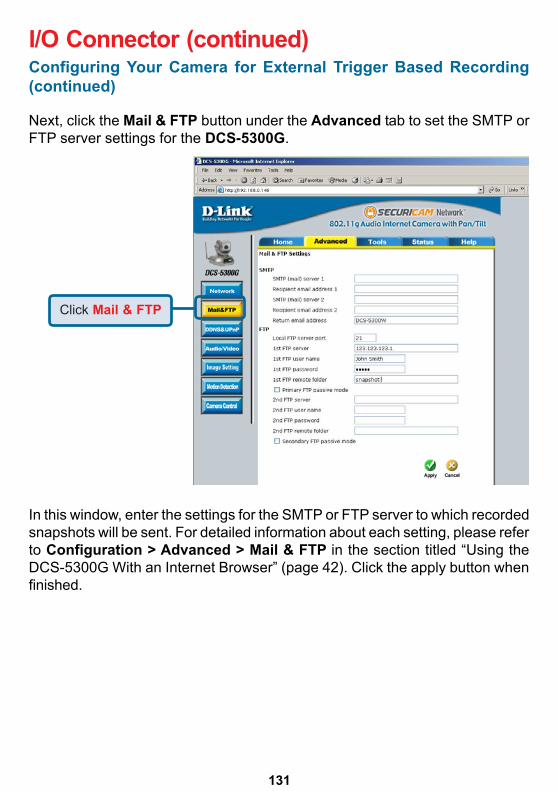
131
In this window, enter the settings for the SMTP or FTP server to which recordedsnapshots will be sent. For detailed information about each setting, please referto Configuration > Advanced > Mail & FTP in the section titled “Using theDCS-5300G With an Internet Browser” (page 42). Click the apply button whenfinished.
Configuring Your Camera for External Trigger Based Recording(continued)
I/O Connector (continued)
Next, click the Mail & FTP button under the Advanced tab to set the SMTP orFTP server settings for the DCS-5300G.
Click Mail & FTP
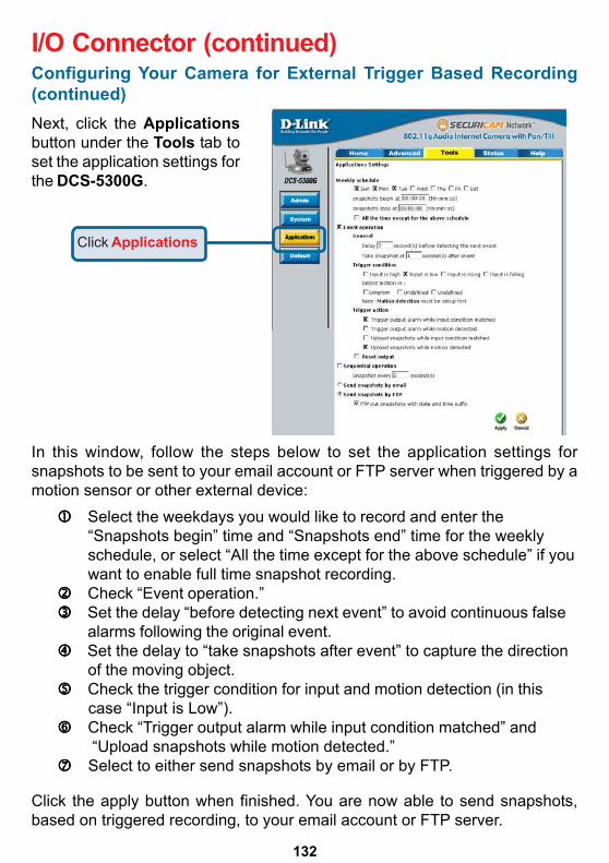
132
Configuring Your Camera for External Trigger Based Recording(continued)
I/O Connector (continued)
In this window, follow the steps below to set the application settings forsnapshots to be sent to your email account or FTP server when triggered by amotion sensor or other external device:
Select the weekdays you would like to record and enter the “Snapshots begin” time and “Snapshots end” time for the weekly schedule, or select “All the time except for the above schedule” if you want to enable full time snapshot recording. Check “Event operation.” Set the delay “before detecting next event” to avoid continuous false alarms following the original event. Set the delay to “take snapshots after event” to capture the direction
of the moving object.55555 Check the trigger condition for input and motion detection (in this
case “Input is Low”).66666 Check “Trigger output alarm while input condition matched” and
“Upload snapshots while motion detected.”77777 Select to either send snapshots by email or by FTP.
Click the apply button when finished. You are now able to send snapshots,based on triggered recording, to your email account or FTP server.
Next, click the Applicationsbutton under the Tools tab toset the application settings forthe DCS-5300G.
Click Applications
X X X
X
X
X
Living room
X
133
Adjusting the Cameras FocusTo adjust the focus of the lens you will need to turn the lens slowly eitherclockwise or counterclockwise until the desired image appears. DO NOT over-turn the lens in either direction as it will be out of focus and may cause damageto the camera.
To help you get the best image quality, keep in mind that while adjusting theDCS-5300G’s focus you can preview the image quality from your Web browser.
Note:You can further adjust the Internet Camera’s image quality throughthe Web Configuration under: Configuration > Advanced > Audio/Video (page 47)Please refer to Using the DCS-5300G with an Internet Browsersection for further details.
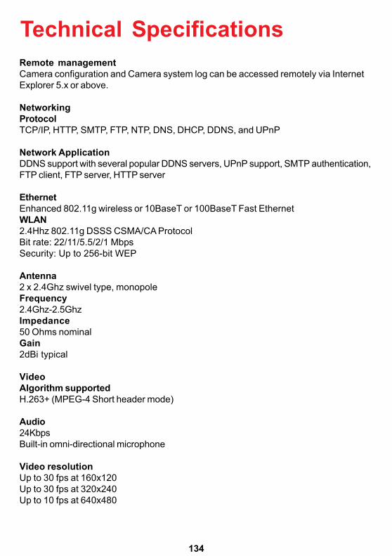
134
Remote managementCamera configuration and Camera system log can be accessed remotely via InternetExplorer 5.x or above.
NetworkingProtocolTCP/IP, HTTP, SMTP, FTP, NTP, DNS, DHCP, DDNS, and UPnP
Network ApplicationDDNS support with several popular DDNS servers, UPnP support, SMTP authentication,FTP client, FTP server, HTTP server
EthernetEnhanced 802.11g wireless or 10BaseT or 100BaseT Fast EthernetWLAN2.4Hhz 802.11g DSSS CSMA/CA ProtocolBit rate: 22/11/5.5/2/1 MbpsSecurity: Up to 256-bit WEP
Antenna2 x 2.4Ghz swivel type, monopoleFrequency2.4Ghz-2.5GhzImpedance50 Ohms nominalGain2dBi typical
VideoAlgorithm supportedH.263+ (MPEG-4 Short header mode)
Audio24KbpsBuilt-in omni-directional microphone
Video resolutionUp to 30 fps at 160x120Up to 30 fps at 320x240Up to 10 fps at 640x480
Technical Specifications
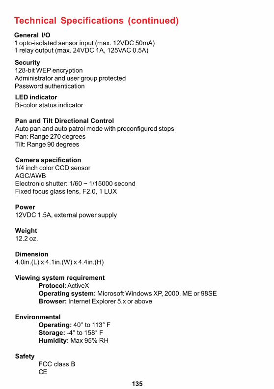
135
LED indicatorBi-color status indicator
Pan and Tilt Directional ControlAuto pan and auto patrol mode with preconfigured stopsPan: Range 270 degreesTilt: Range 90 degrees
Camera specification1/4 inch color CCD sensorAGC/AWBElectronic shutter: 1/60 ~ 1/15000 secondFixed focus glass lens, F2.0, 1 LUX
Power12VDC 1.5A, external power supply
Weight12.2 oz.
Dimension4.0in.(L) x 4.1in.(W) x 4.4in.(H)
Viewing system requirementProtocol: ActiveXOperating system: Microsoft Windows XP, 2000, ME or 98SEBrowser: Internet Explorer 5.x or above
EnvironmentalOperating: 40° to 113° FStorage: -4° to 158° FHumidity: Max 95% RH
SafetyFCC class BCE
Technical Specifications (continued)
Security128-bit WEP encryptionAdministrator and user group protectedPassword authentication
General I/O1 opto-isolated sensor input (max. 12VDC 50mA)1 relay output (max. 24VDC 1A, 125VAC 0.5A)

136
Contacting Technical Support
Technical SupportTechnical SupportTechnical SupportTechnical SupportTechnical SupportYou can find software updates and user documentation on the D-Link website.
D-Link provides free technical support for customers within the United States andwithin Canada for the duration of the warranty period on this product.
U.S. and Canadian customers can contact D-Link Technical Support through ourwebsite, or by phone.
Tech Support for customers within the United States:D-Link Technical Support over the Telephone:(877) 453-546524 hours a day, seven days a week.
D-Link Technical Support over the Internet:http://support.dlink.comemail:[email protected]
Tech Support for customers within Canada:D-Link Technical Support over the Telephone:(800) 361-5265Monday to Friday 7:30am to 12:00am EST
D-Link Technical Support over the Internet:http://support.dlink.caemail:[email protected]

137
Time Zone TableGMT stands for Greenwich Mean Time, which is the global time that alltime zones are measured from.

138
Time Zone Table (continued)

139
Subject to the terms and conditions set forth herein, D-Link Systems, Inc. (“D-Link”) provides this Limitedwarranty for its product only to the person or entity that originally purchased the product from:• D-Link or its authorized reseller or distributor and• Products purchased and delivered within the fifty states of the United States, the District of Columbia,
U.S. Possessions or Protectorates, U.S. Military Installations, addresses with an APO or FPO.Limited Warranty: D-Link warrants that the hardware portion of the D-Link products described below will befree from material defects in workmanship and materials from the date of original retail purchase of theproduct, for the period set forth below applicable to the product type (“Warranty Period”), except as otherwisestated herein.1-Year Limited Warranty for the Product(s) is defined as follows:
• Hardware (excluding power supplies and fans) One (1) Year• Power Supplies and Fans One (1) Year• Spare parts and spare kits Ninety (90) daysD-Link’s sole obligation shall be to repair or replace the defective Hardware during the Warranty Period at nocharge to the original owner or to refund at D-Link’s sole discretion. Such repair or replacement will berendered by D-Link at an Authorized D-Link Service Office. The replacement Hardware need not be new orhave an identical make, model or part. D-Link may in its sole discretion replace the defective Hardware (orany part thereof) with any reconditioned product that D-Link reasonably determines is substantially equivalent(or superior) in all material respects to the defective Hardware. Repaired or replacement Hardware will bewarranted for the remainder of the original Warranty Period from the date of original retail purchase. If amaterial defect is incapable of correction, or if D-Link determines in its sole discretion that it is not practicalto repair or replace the defective Hardware, the price paid by the original purchaser for the defective Hardwarewill be refunded by D-Link upon return to D-Link of the defective Hardware. All Hardware (or part thereof) thatis replaced by D-Link, or for which the purchase price is refunded, shall become the property of D-Link uponreplacement or refund.Limited Software Warranty: D-Link warrants that the software portion of the product (“Software”) willsubstantially conform to D-Link’s then current functional specifications for the Software, as set forth in theapplicable documentation, from the date of original retail purchase of the Software for a period of ninety (90)days (“Warranty Period”), provided that the Software is properly installed on approved hardware and operatedas contemplated in its documentation. D-Link further warrants that, during the Warranty Period, the magneticmedia on which D-Link delivers the Software will be free of physical defects. D-Link’s sole obligation shall beto replace the non-conforming Software (or defective media) with software that substantially conforms to D-Link’s functional specifications for the Software or to refund at D-Link’s sole discretion. Except as otherwiseagreed by D-Link in writing, the replacement Software is provided only to the original licensee, and is subjectto the terms and conditions of the license granted by D-Link for the Software. Software will be warranted forthe remainder of the original Warranty Period from the date or original retail purchase. If a material non-conformance is incapable of correction, or if D-Link determines in its sole discretion that it is not practical toreplace the non-conforming Software, the price paid by the original licensee for the non-conforming Softwarewill be refunded by D-Link; provided that the non-conforming Software (and all copies thereof) is first returnedto D-Link. The license granted respecting any Software for which a refund is given automatically terminates.Non-Applicability of Warranty: The Limited Warranty provided hereunder for hardware and software of D-Link’s products will not be applied to and does not cover any refurbished product and any product purchasedthrough the inventory clearance or liquidation sale or other sales in which D-Link, the sellers, or the liquidatorsexpressly disclaim their warranty obligation pertaining to the product and in that case, the product is beingsold “As-Is” without any warranty whatsoever including, without limitation, the Limited Warranty as describedherein, notwithstanding anything stated herein to the contrary.
Submitting A Claim: The customer shall return the product to the original purchase point based on itsreturn policy. In case the return policy period has expired and the product is within warranty, the customershall submit a claim to D-Link as outlined below:
• The customer must submit with the product as part of the claim a written description of the Hardwaredefect or Software nonconformance in sufficient detail to allow D-Link to confirm the same.
Warranty and RegistrationUSA only
• The original product owner must obtain a Return Material Authorization (“RMA”) number from theAuthorized D-Link Service Office and, if requested, provide written proof of purchase of the product (suchas a copy of the dated purchase invoice for the product) before the warranty service is provided.

140
• After an RMA number is issued, the defective product must be packaged securely in the original orother suitable shipping package to ensure that it will not be damaged in transit, and the RMA numbermust be prominently marked on the outside of the package. Do not include any manuals or accessoriesin the shipping package. D-Link will only replace the defective portion of the Product and will not shipback any accessories.
• The customer is responsible for all in-bound shipping charges to D-Link. No Cash on Delivery(“COD”) is allowed. Products sent COD will either be rejected by D-Link or become the property of D-Link. Products shall be fully insured by the customer and shipped to D-Link Systems, Inc., 17595Mt. Herrmann, Fountain Valley, CA 92708. D-Link will not be held responsible for any packagesthat are lost in transit to D-Link. The repaired or replaced packages will be shipped to the customervia UPS Ground or any common carrier selected by D-Link, with shipping charges prepaid. Expeditedshipping is available if shipping charges are prepaid by the customer and upon request.
D-Link may reject or return any product that is not packaged and shipped in strict compliance with theforegoing requirements, or for which an RMA number is not visible from the outside of the package. Theproduct owner agrees to pay D-Link’s reasonable handling and return shipping charges for any product thatis not packaged and shipped in accordance with the foregoing requirements, or that is determined by D-Linknot to be defective or non-conforming.What Is Not Covered: This limited warranty provided by D-Link does not cover: Products, if in D-Link’sjudgment, have been subjected to abuse, accident, alteration, modification, tampering, negligence, misuse,faulty installation, lack of reasonable care, repair or service in any way that is not contemplated in thedocumentation for the product, or if the model or serial number has been altered, tampered with, defaced orremoved; Initial installation, installation and removal of the product for repair, and shipping costs; Operationaladjustments covered in the operating manual for the product, and normal maintenance; Damage that occursin shipment, due to act of God, failures due to power surge, and cosmetic damage; Any hardware, software,firmware or other products or services provided by anyone other than D-Link; Products that have beenpurchased from inventory clearance or liquidation sales or other sales in which D-Link, the sellers, or theliquidators expressly disclaim their warranty obligation pertaining to the product. Repair by anyone otherthan D-Link or an Authorized D-Link Service Office will void this Warranty.Disclaimer of Other Warranties: EXCEPT FOR THE LIMITED WARRANTY SPECIFIED HEREIN, THEPRODUCT IS PROVIDED “AS-IS” WITHOUT ANY WARRANTY OF ANY KIND WHATSOEVER INCLUDING,WITHOUT LIMITATION, ANY WARRANTY OF MERCHANTABILITY, FITNESS FOR A PARTICULAR PURPOSEAND NON-INFRINGEMENT. IF ANY IMPLIED WARRANTY CANNOT BE DISCLAIMED IN ANY TERRITORYWHERE A PRODUCT IS SOLD, THE DURATION OF SUCH IMPLIED WARRANTY SHALL BE LIMITED TONINETY (90) DAYS. EXCEPT AS EXPRESSLY COVERED UNDER THE LIMITED WARRANTY PROVIDEDHEREIN, THE ENTIRE RISK AS TO THE QUALITY, SELECTION AND PERFORMANCE OF THE PRODUCTIS WITH THE PURCHASER OF THE PRODUCT.Limitation of Liability: TO THE MAXIMUM EXTENT PERMITTED BY LAW, D-LINK IS NOT LIABLE UNDERANY CONTRACT, NEGLIGENCE, STRICT LIABILITY OR OTHER LEGAL OR EQUITABLE THEORY FORANY LOSS OF USE OF THE PRODUCT, INCONVENIENCE OR DAMAGES OF ANY CHARACTER,WHETHER DIRECT, SPECIAL, INCIDENTAL OR CONSEQUENTIAL (INCLUDING, BUT NOT LIMITED TO,DAMAGES FOR LOSS OF GOODWILL, LOSS OF REVENUE OR PROFIT, WORK STOPPAGE, COMPUTERFAILURE OR MALFUNCTION, FAILURE OF OTHER EQUIPMENT OR COMPUTER PROGRAMS TO WHICHD-LINK’S PRODUCT IS CONNECTED WITH, LOSS OF INFORMATION OR DATA CONTAINED IN, STOREDON, OR INTEGRATED WITH ANY PRODUCT RETURNED TO D-LINK FOR WARRANTY SERVICE)RESULTING FROM THE USE OF THE PRODUCT, RELATING TO WARRANTY SERVICE, OR ARISINGOUT OF ANY BREACH OF THIS LIMITED WARRANTY, EVEN IF D-LINK HAS BEEN ADVISED OF THEPOSSIBILITY OF SUCH DAMAGES. THE SOLE REMEDY FOR A BREACH OF THE FOREGOING LIMITEDWARRANTY IS REPAIR, REPLACEMENT OR REFUND OF THE DEFECTIVE OR NON-CONFORMINGPRODUCT. THE MAXIMUM LIABILITY OF D-LINK UNDER THIS WARRANTY IS LIMITED TO THE PURCHASEPRICE OF THE PRODUCT COVERED BY THE WARRANTY. THE FOREGOING EXPRESS WRITTENWARRANTIES AND REMEDIES ARE EXCLUSIVE AND ARE IN LIEU OF ANY OTHER WARRANTIES ORREMEDIES, EXPRESS, IMPLIED OR STATUTORYGoverning Law: This Limited Warranty shall be governed by the laws of the State of California. Some statesdo not allow exclusion or limitation of incidental or consequential damages, or limitations on how long animplied warranty lasts, so the foregoing limitations and exclusions may not apply. This limited warrantyprovides specific legal rights and the product owner may also have other rights which vary from state to state.
Warranty and RegistrationUSA only (continued)
141
Trademarks: D-Link is a registered trademark of D-Link Systems, Inc. Other trademarks or registeredtrademarks are the property of their respective manufacturers or owners.
Copyright Statement: No part of this publication or documentation accompanyingthis Product may be reproduced in any form or by any means or used to make anyderivative such as translation, transformation, or adaptation without permission fromD-Link Corporation/D-Link Systems, Inc., as stipulated by the United StatesCopyright Act of 1976. Contents are subject to change without prior notice.Copyright© 2002 by D-Link Corporation/D-Link Systems, Inc. All rights reserved.
CE Mark Warning: This is a Class B product. In a domestic environment, this product may cause radiointerference, in which case the user may be required to take adequate measures.
FCC Statement: This equipment has been tested and found to comply with the limits for a Class B digitaldevice, pursuant to part 15 of the FCC Rules. These limits are designed to provide reasonable protectionagainst harmful interference in a residential installation. This equipment generates, uses, and can radiateradio frequency energy and, if not installed and used in accordance with the instructions, may cause harmfulinterference to radio communication. However, there is no guarantee that interference will not occur in aparticular installation. If this equipment does cause harmful interference to radio or television reception,which can be determined by turning the equipment off and on, the user is encouraged to try to correct theinterference by one or more of the following measures:• Reorient or relocate the receiving antenna.• Increase the separation between the equipment and receiver.• Connect the equipment into an outlet on a circuit different from that to which the receiver is connected.• Consult the dealer or an experienced radio/TV technician for help.
Warranty and RegistrationUSA only (continued)
For detailed warranty outside the United States, please contact corresponding localD-Link office.
Register online your D-Link product at http://support.dlink.com/register/
Register online your D-Link product at http://support.dlink.com/register/
07/16/04