Embed Size (px)
Citation preview

DCN286 INTRODUCTION TO DATA COMMUNICATION TECHNOLOGY
Ethernet Fundamentals
Introduction to Ethernet
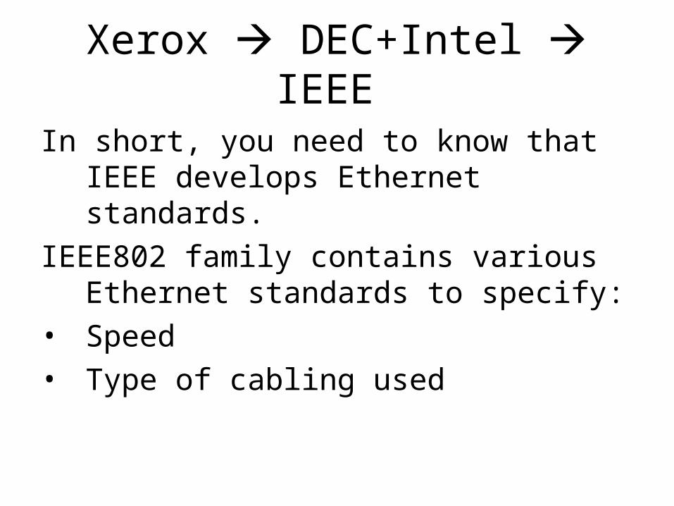
Xerox DEC+Intel IEEE
In short, you need to know that IEEE develops Ethernet standards.
IEEE802 family contains various Ethernet standards to specify:
• Speed
• Type of cabling used
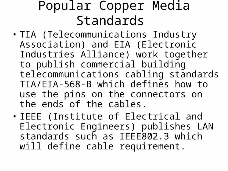
Popular Copper Media Standards
• TIA (Telecommunications Industry Association) and EIA (Electronic Industries Alliance) work together to publish commercial building telecommunications cabling standards TIA/EIA-568-B which defines how to use the pins on the connectors on the ends of the cables.
• IEEE (Institute of Electrical and Electronic Engineers) publishes LAN standards such as IEEE802.3 which will define cable requirement.
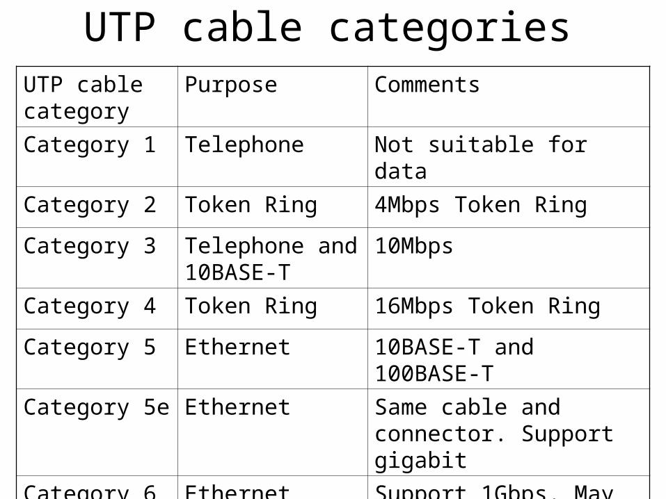
UTP cable categoriesUTP cable category
Purpose Comments
Category 1 Telephone Not suitable for data
Category 2 Token Ring 4Mbps Token Ring
Category 3 Telephone and 10BASE-T
10Mbps
Category 4 Token Ring 16Mbps Token Ring
Category 5 Ethernet 10BASE-T and 100BASE-T
Category 5e Ethernet Same cable and connector. Support gigabit
Category 6 Ethernet Support 1Gbps. May support 10Gbps
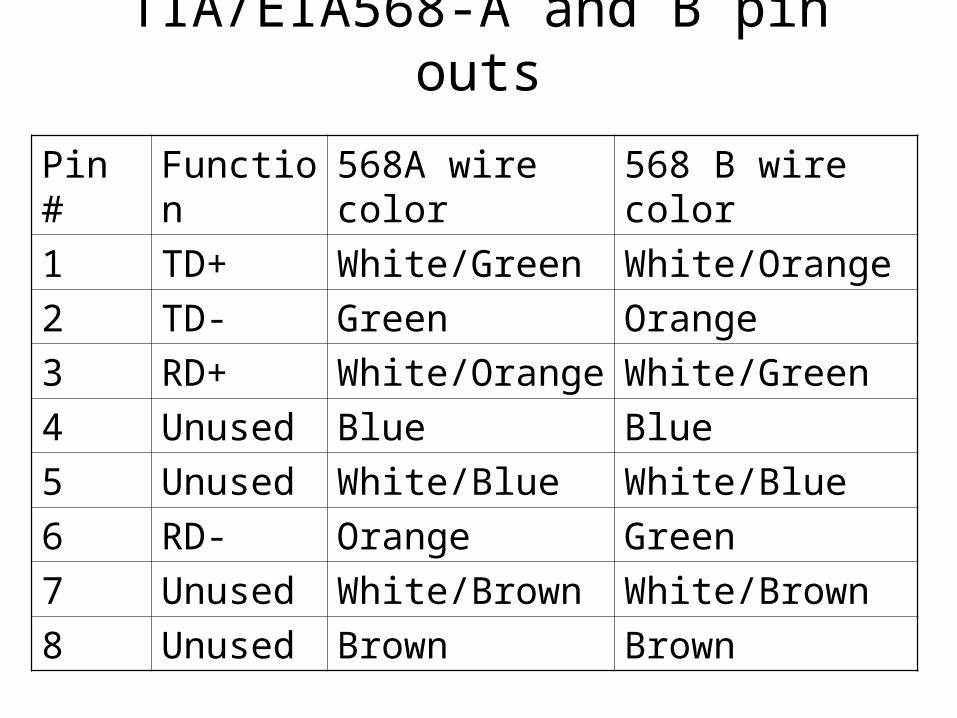
TIA/EIA568-A and B pin outs
Pin # Function 568A wire color 568 B wire color
1 TD+ White/Green White/Orange
2 TD- Green Orange
3 RD+ White/Orange White/Green
4 Unused Blue Blue
5 Unused White/Blue White/Blue
6 RD- Orange Green
7 Unused White/Brown White/Brown
8 Unused Brown Brown
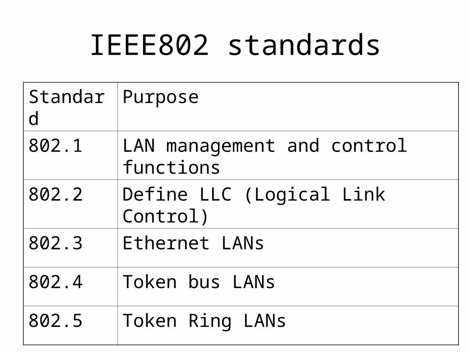
IEEE802 standards
Standard Purpose
802.1 LAN management and control functions
802.2 Define LLC (Logical Link Control)
802.3 Ethernet LANs
802.4 Token bus LANs
802.5 Token Ring LANs
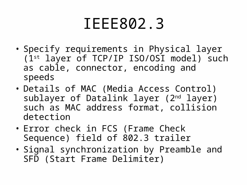
IEEE802.3
• Specify requirements in Physical layer (1st layer of TCP/IP ISO/OSI model) such as cable, connector, encoding and speeds
• Details of MAC (Media Access Control) sublayer of Datalink layer (2nd layer) such as MAC address format, collision detection
• Error check in FCS (Frame Check Sequence) field of 802.3 trailer
• Signal synchronization by Preamble and SFD (Start Frame Delimiter)
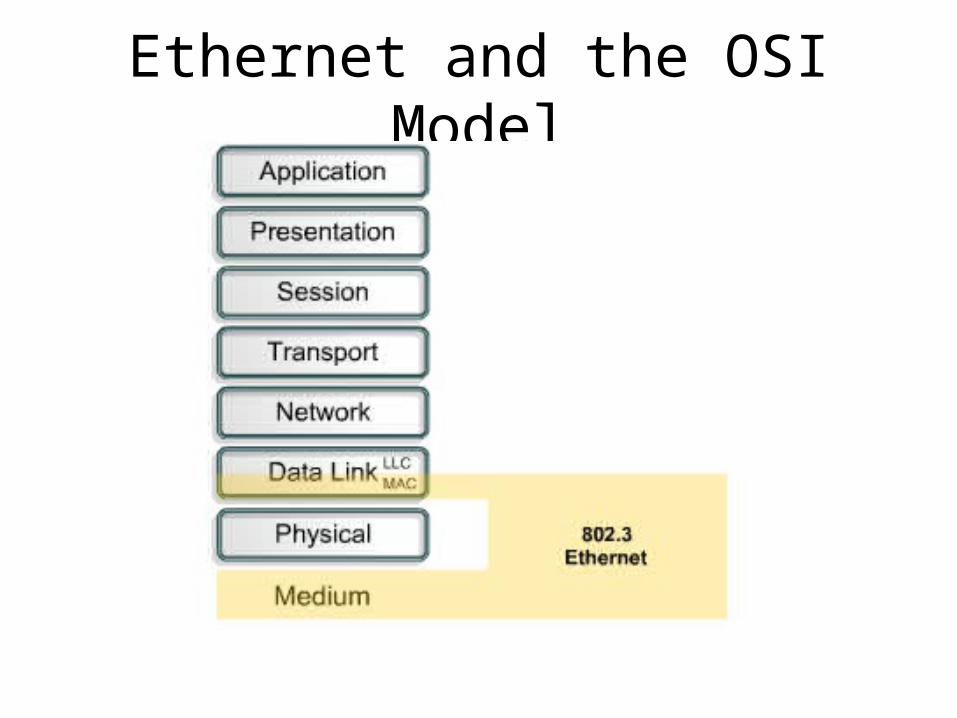
Ethernet and the OSI Model
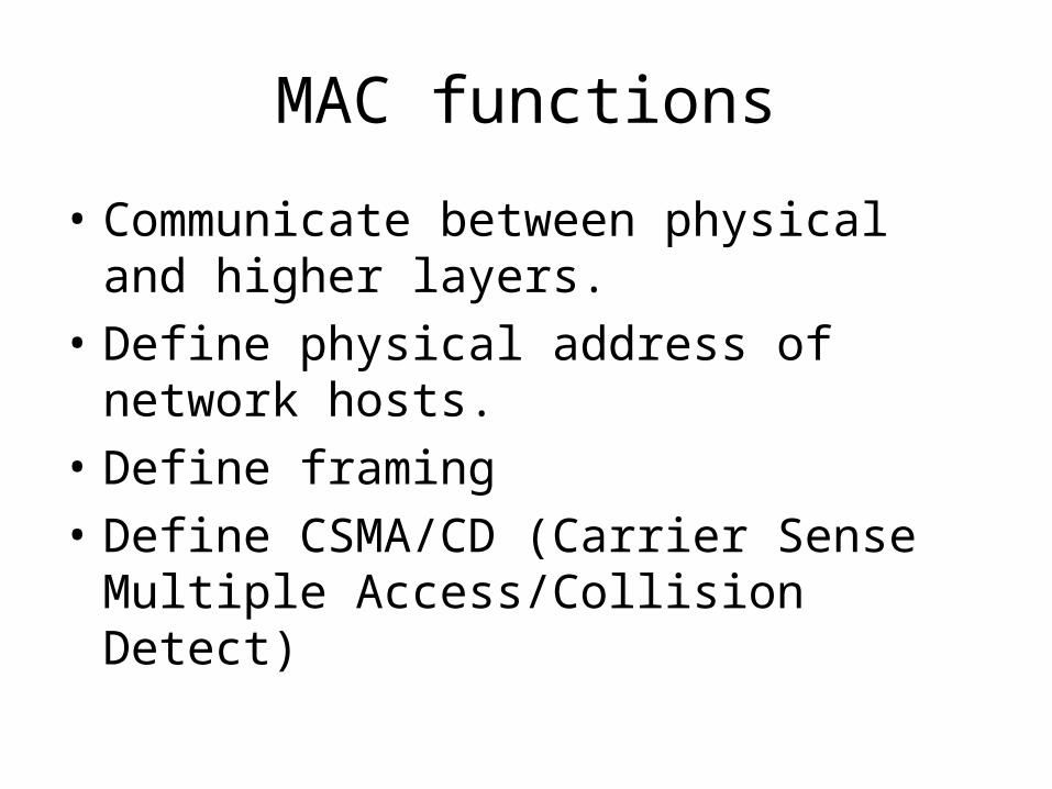
MAC functions
• Communicate between physical and higher layers.
• Define physical address of network hosts.
• Define framing
• Define CSMA/CD (Carrier Sense Multiple Access/Collision Detect)
Framing
• The process of encapsulating data inside a header and possibly a trailer
• The meaning given to the bits inside those headers and trailers
• All IEEE Ethernet standards use the same framing.
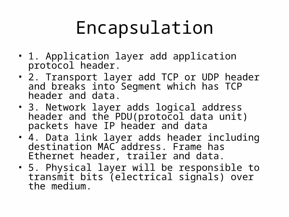
• 1. Application layer add application protocol header.• 2. Transport layer add TCP or UDP header and breaks
into Segment which has TCP header and data.• 3. Network layer adds logical address header and the
PDU(protocol data unit) packets have IP header and data
• 4. Data link layer adds header including destination MAC address. Frame has Ethernet header, trailer and data.
• 5. Physical layer will be responsible to transmit bits (electrical signals) over the medium.
Encapsulation
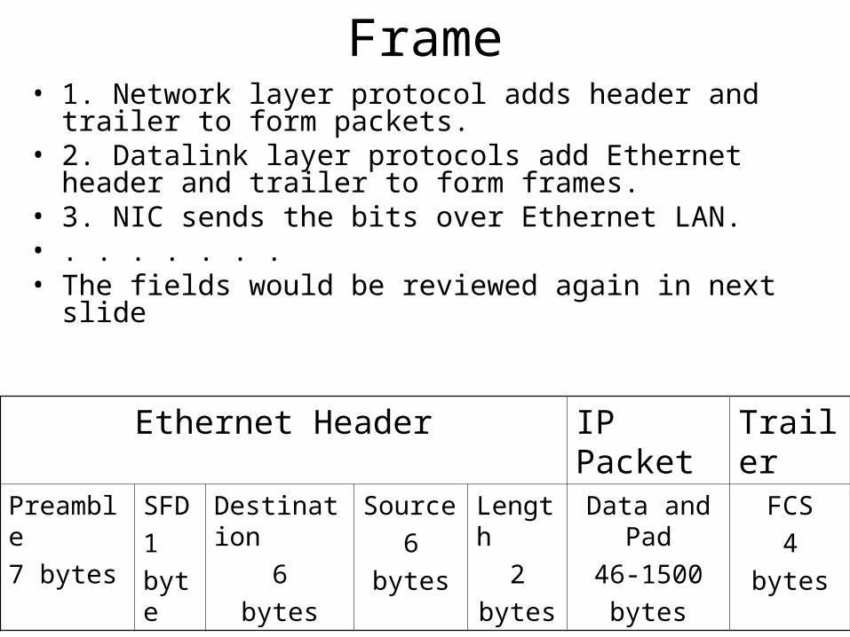
Frame
Ethernet Header IP Packet Trailer
Preamble
7 bytes
SFD
1
byte
Destination
6
bytes
Source
6
bytes
Length
2
bytes
Data and Pad
46-1500
bytes
FCS
4
bytes
• 1. Network layer protocol adds header and trailer to form packets.
• 2. Datalink layer protocols add Ethernet header and trailer to form frames.
• 3. NIC sends the bits over Ethernet LAN.• . . . . . . .• The fields would be reviewed again in next slide
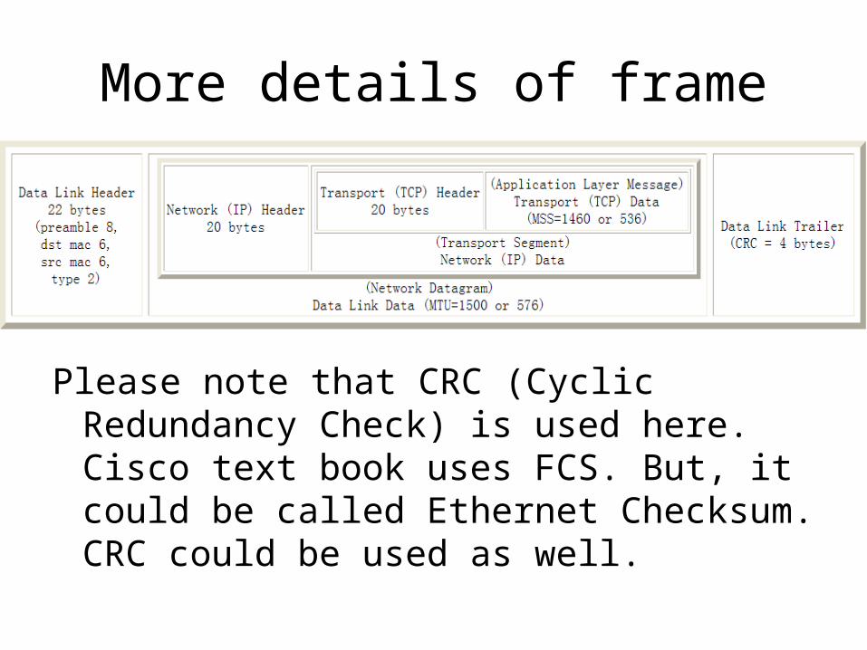
More details of frame
Please note that CRC (Cyclic Redundancy Check) is used here. Cisco text book uses FCS. But, it could be called Ethernet Checksum. CRC could be used as well.
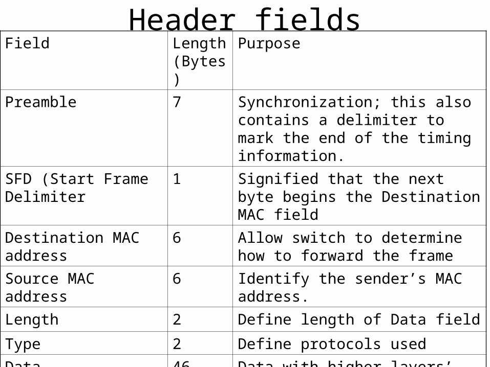
Header fieldsField Length
(Bytes)Purpose
Preamble 7 Synchronization; this also contains a delimiter to mark the end of the timing information.
SFD (Start Frame Delimiter
1 Signified that the next byte begins the Destination MAC field
Destination MAC address
6 Allow switch to determine how to forward the frame
Source MAC address 6 Identify the sender’s MAC address.
Length 2 Define length of Data field
Type 2 Define protocols used
Data 46-1500 Data with higher layers’ header/trailer
Frame Check Sequence (FCS)
4 Receiver can re-calculate CRC and compare the result with sender’s.
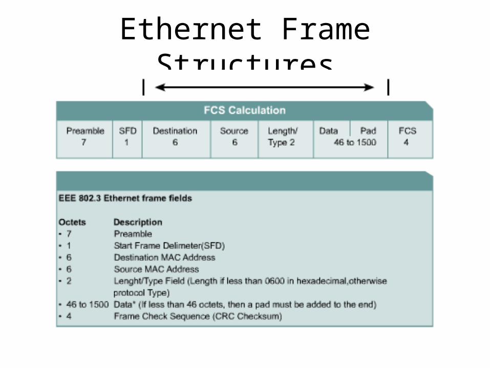
Ethernet Frame Structures
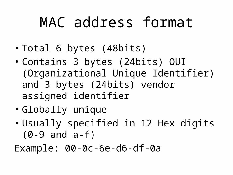
MAC address format
• Total 6 bytes (48bits)
• Contains 3 bytes (24bits) OUI (Organizational Unique Identifier) and 3 bytes (24bits) vendor assigned identifier
• Globally unique
• Usually specified in 12 Hex digits (0-9 and a-f)
Example: 00-0c-6e-d6-df-0a
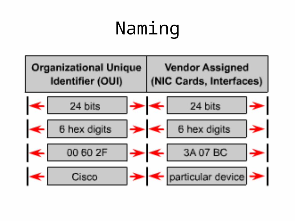
Naming
IEEE802.2 LLC
Basic features:
• Identify the type of data inside the frames’ data field
• Control the transmissions and perform error detection and recovery
IEEE802.2 header
IEEE802.2 header has fields containing:
• SSAP: Source Service Access Point
• DSAP: Destination Service Access Point
SNAP (Subnetwork Access Protocol) header is used when DSAP cannot contain so many protocol types informaitn
CSMA/CD (Carrier Sense Multiple Access/Collision Detect)
• Carrier Sense: all devices listen
• Multiple Access: more than one devices start sending signals. Collision occurs when two devices send signals at the same time leading their electrical signals to overlap.
• Collision Detect: detect the collision, sending out jam signals and wait for next try.
• Half Duplex logic is used in CSMA/CD
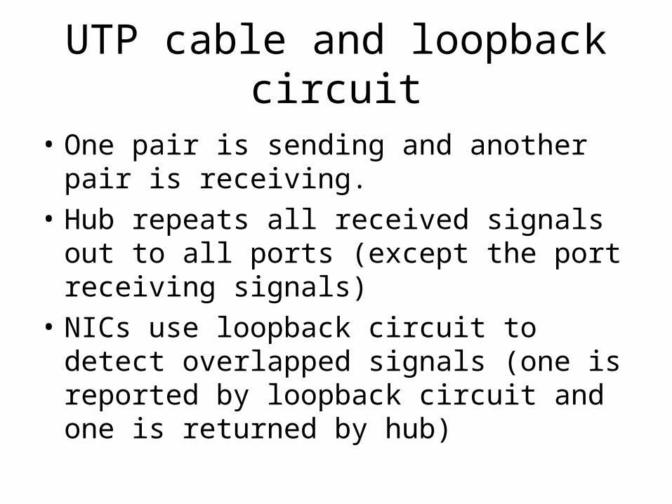
UTP cable and loopback circuit
• One pair is sending and another pair is receiving.
• Hub repeats all received signals out to all ports (except the port receiving signals)
• NICs use loopback circuit to detect overlapped signals (one is reported by loopback circuit and one is returned by hub)
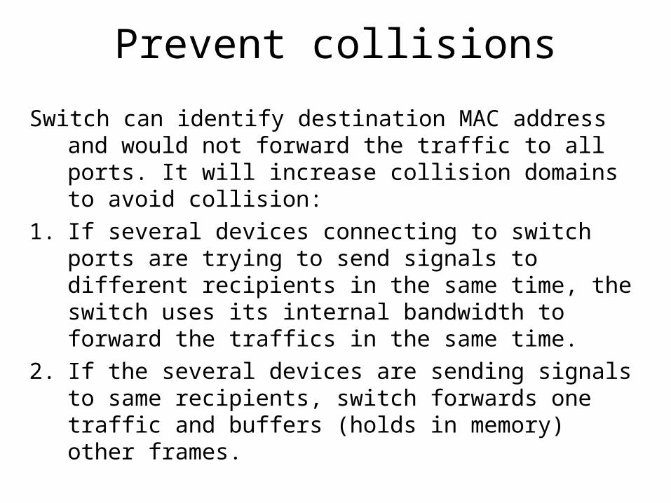
Prevent collisions
Switch can identify destination MAC address and would not forward the traffic to all ports. It will increase collision domains to avoid collision:
1. If several devices connecting to switch ports are trying to send signals to different recipients in the same time, the switch uses its internal bandwidth to forward the traffics in the same time.
2. If the several devices are sending signals to same recipients, switch forwards one traffic and buffers (holds in memory) other frames.
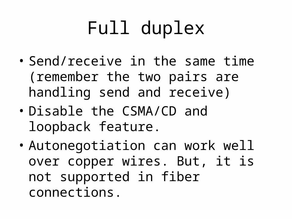
Full duplex
• Send/receive in the same time (remember the two pairs are handling send and receive)
• Disable the CSMA/CD and loopback feature.
• Autonegotiation can work well over copper wires. But, it is not supported in fiber connections.
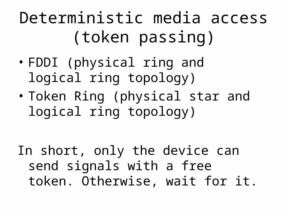
Deterministic media access (token passing)
• FDDI (physical ring and logical ring topology)
• Token Ring (physical star and logical ring topology)
In short, only the device can send signals with a free token. Otherwise, wait for it.
WLAN (Wireless LAN) collision avoidance
• WLAN is in half duplex mode and using CSMA/CA (CSMA with Collision Avoidance)
• Collision detection is not possible in WLAN.
Two reasons:1. Each wireless station has one antenna for both sending
and receiving. Hence we can’t use the same antenna for both transmitting and at the same time detecting collisions. Even if we have two antennas, it will be difficult to detect collision. Because the transmitting signal power will be much higher than the incoming signal, it will not recognize any collision.
2. In wireless, only the receiver is in problem, not the transmitter. We need to detect collision at the receivers end and the sender is not able to tell it whether there is a collision in receivers end.
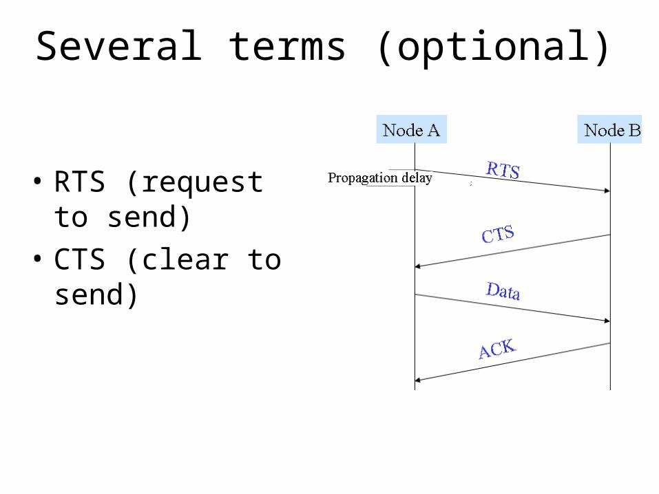
Several terms (optional)
• RTS (request to send)
• CTS (clear to send)
Question
Any question?
If you do not have question, please search internet and collect more information of those IEEE802 standards.
1. Please be comfortable to explain collision detection and avoidance process.
2. Please be familiar with those organizations’ full name and main responsibilities.