Embed Size (px)
Citation preview
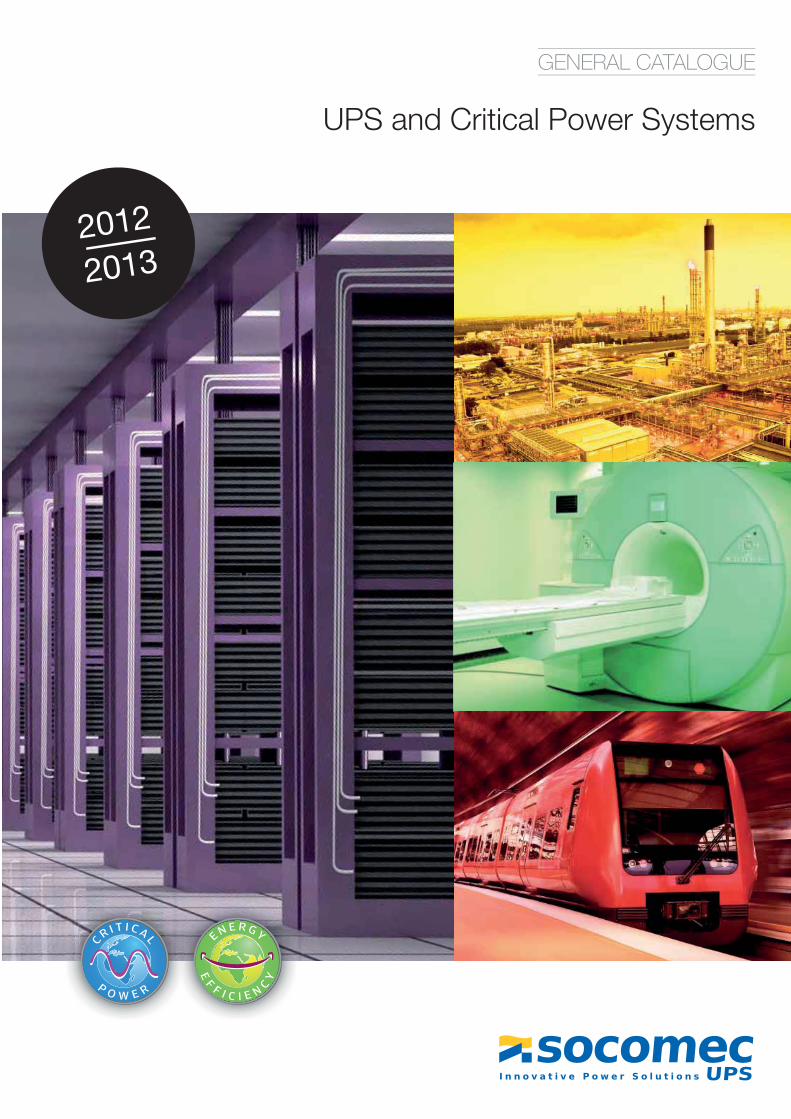
2012
2013
UPS and Critical Power Systems
GENERAL CATALOGUE
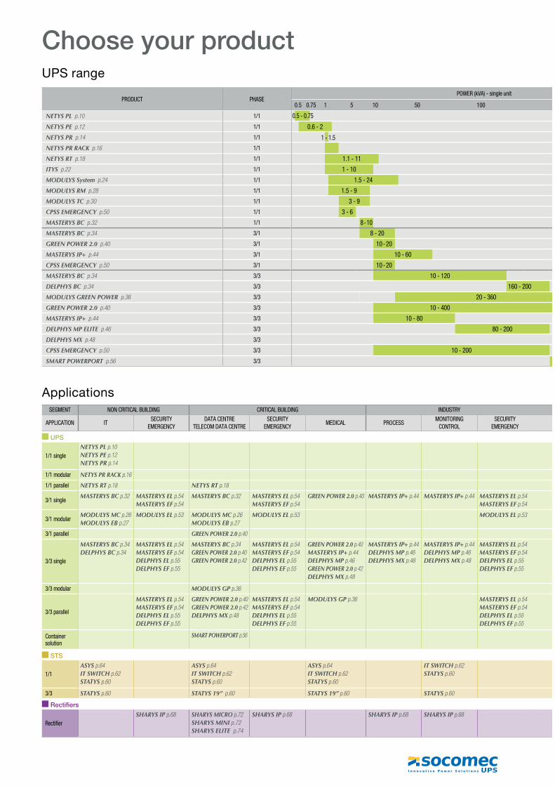
Choose your productUPS range
PRODUCT PHASEPOWER (kVA) - single unit
0.5 0.75 1 5 10 50 100
NETYS PL��p.10 1/1
NETYS PE��p.12 1/1 0.6 - 2
NETYS PR��p.14 1/1
NETYS PR RACK��p.16 1/1
NETYS RT��p.18 1/1 1.1 - 11
ITYS��p.22 1/1 1 - 10
MODULYS System��p.24 1/1 1.5 - 24
MODULYS RM��p.28 1/1 1.5 - 9
MODULYS TC��p.30 1/1 3 - 9
CPSS EMERGENCY��p.50 1/1 3 - 6
MASTERYS BC��p.32 1/1 8 - 10
MASTERYS BC��p.34 3/1 8 - 20
GREEN POWER 2.0��p.40 3/1 10 - 20
MASTERYS IP+��p.44 3/1 10 - 60
CPSS EMERGENCY��p.50 3/1 10 - 20
MASTERYS BC��p.34 3/3 10 - 120
DELPHYS BC��p.34 3/3 160 - 200
MODULYS GREEN POWER��p.36 3/3 20 - 360
GREEN POWER 2.0��p.40 3/3 10 - 400
MASTERYS IP+��p.44 3/3 10 - 80
DELPHYS MP ELITE��p.46 3/3 80 - 200
DELPHYS MX��p.48 3/3
CPSS EMERGENCY��p.50 3/3 10 - 200
SMART POWERPORT��p.56 3/3
ApplicationsSEGMENT NON CRITICAL BUILDING CRITICAL BUILDING INDUSTRY
APPLICATION ITSECURITY
EMERGENCYDATA CENTRE
TELECOM DATA CENTRESECURITY
EMERGENCYMEDICAL PROCESS
MONITORING CONTROL
SECURITY EMERGENCY
UPS
1/1 singleNETYS PL�p.10NETYS PE�p.12NETYS PR�p.14
1/1 modular NETYS PR RACK�p.16
1/1 parallel NETYS RT�p.18 NETYS RT�p.18
3/1 singleMASTERYS BC�p.32 MASTERYS EL�p.54
MASTERYS EF�p.54MASTERYS BC�p.32 MASTERYS EL�p.54
MASTERYS EF�p.54GREEN POWER 2.0�p.40 MASTERYS IP+�p.44 MASTERYS IP+�p.44 MASTERYS EL�p.54
MASTERYS EF�p.54
3/1 modularMODULYS MC�p.26MODULYS EB�p.27
MODULYS EL�p.53 MODULYS MC�p.26MODULYS EB�p.27
MODULYS EL�p.53 MODULYS EL�p.53
3/1 parallel GREEN POWER 2.0�p.40
3/3 single
MASTERYS BC�p.34DELPHYS BC�p.34
MASTERYS EL�p.54MASTERYS EF�p.54DELPHYS EL�p.55DELPHYS EF�p.55
MASTERYS BC�p.34GREEN POWER 2.0�p.40GREEN POWER 2.0�p.42
MASTERYS EL�p.54MASTERYS EF�p.54DELPHYS EL�p.55DELPHYS EF�p.55
GREEN POWER 2.0�p.40MASTERYS IP+�p.44DELPHYS MP�p.46GREEN POWER 2.0�p.42DELPHYS MX�p.48
MASTERYS IP+�p.44DELPHYS MP�p.46DELPHYS MX�p.48
MASTERYS IP+�p.44DELPHYS MP�p.46DELPHYS MX�p.48
MASTERYS EL�p.54MASTERYS EF�p.54DELPHYS EL�p.55DELPHYS EF�p.55
3/3 modular MODULYS GP�p.36
3/3 parallel
MASTERYS EL�p.54MASTERYS EF�p.54DELPHYS EL�p.55DELPHYS EF�p.55
GREEN POWER 2.0�p.40GREEN POWER 2.0�p.42DELPHYS MX�p.48
MASTERYS EL�p.54MASTERYS EF�p.54DELPHYS EL�p.55DELPHYS EF�p.55
MODULYS GP�p.36 MASTERYS EL�p.54MASTERYS EF�p.54DELPHYS EL�p.55DELPHYS EF�p.55
Container solution
SMART POWERPORT�p.56
STS
1/1ASYS�p.64IT SWITCH�p.62STATYS�p.60
ASYS�p.64IT SWITCH�p.62STATYS�p.60
ASYS�p.64IT SWITCH�p.62STATYS�p.60
IT SWITCH�p.62STATYS�p.60
3/3 STATYS�p.60 STATYS 19” �p.60 STATYS 19”�p.60 STATYS�p.60
Rectifiers
RectifierSHARYS IP�p.68 SHARYS MICRO�p.72
SHARYS MINI�p.72SHARYS ELITE �p.74
SHARYS IP�p.68 SHARYS IP�p.68 SHARYS IP�p.68
0.5 - 0.75
1 - 1.5
General Catalogue 2012 - 2013 1
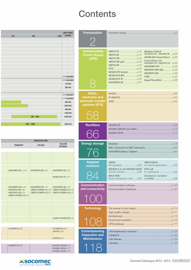
Presentation
2Socomec Group� ..........................................................................p.2
UninterruptiblePower Supply
(UPS)
8
N TYS PL� ..........................p.10N TYS PE� ..........................p.12N TYS PR� ..........................p.14N TYS PR rack� ..................p.16N TYS RT� ..........................p.18ITYS� ...................................p.22MODULYS System� .............p.24MODULYS RM� ..................p.28MODULYS TC� ...................p.30MASTERYS BC� ...................p.32
Business Critical MASTERYS BC - DELPHYS BC� ..p.34MODULYS Green Power� ...p.36Green Power 2.0MASTERYS GP - DELPHYS GP� ..p.40MASTERYS IP+� ..................p.44DELPHYS MP elite� .............p.46DELPHYS MX� ....................p.48CPSS� ..................................p.50Smart PowerPort� ...............p.56
Static, electronic and
automatic transfer systems (STS)
58
STATYS� .......................................................................................p.60
IT SWITCH� .................................................................................p.62
ASYS� ..........................................................................................p.64
Recti� ers
66SHARYS IP� .................................................................................p.68
SHARYS MICRO and MINI� .......................................................p.72
SHARYS ELITE� ...........................................................................p.74
Energy storage
76Flywheel�.....................................................................................p.78
BHC Universal and BHC Interactive� .........................................p.80
MASTERYS Battery Cabinets� .....................................................p.82
Adaptedsolutions
84ATRYS��H3 equalizers� .....................p.86
PHASYS S.A. and PHASYS ELITE��DC/AC inverters� .................p.88
RACK PDU��Power Distribution Units� .....p.90
N TYS RT-M��for marine applications� .......p.92
ITYS cab��for substations� ...................p.94
Solutions in container or shelter� ...........................p.98
Communication and connectivity
100Communication software� ........................................................p.102
Communication interfaces� ......................................................p.107
Technology
108The answer to your needs� ......................................................p.110
High quality voltage� ................................................................p.111
Architectures� ...........................................................................p.113
Economical operation� .............................................................p.116
UPS interfaces � .......................................................................p.117
Commissioning Inspection and Maintenance
118
CIM maintenance contracts� .....................................................p.122
T.SERVICE� ................................................................................p.123
CIM Thermo� ............................................................................p.124
CIM Rent� .................................................................................p.126
MAX POWER(parallel)250 500 1000
-
-
-
-
-
-
-
-
-
-
1+1 redundant
1+1 redundant
120 kVA
360 kVA
-
1+1 redundant
1+1 redundant
360 kVA
2400 kVA
480 kVA
1200 kVA
250 - 900 5400 kVA
-
200 - 1000 2400 kVA
Contents
INFRASTRUCTURE
TRANSPORT UTILITIESTELECOM NETWORK
MASTERYS IP+ �p.44 MASTERYS BC�p.32 MASTERYS BC�p.32
MODULYS TC�p.30
MASTERYS IP+�p.44DELPHYS MP�p.46DELPHYS MX�p.48GREEN POWER 2.0�p.40
MASTERYS BC�p.34GREEN POWER 2.0�p.40GREEN POWER 2.0�p.42
MASTERYS BC�p.34GREEN POWER 2.0�p.40GREEN POWER 2.0�p.42
SMART POWERPORT�p.56
IT SWITCH�p.62 IT SWITCH�p.62STATYS�p.60
STATYS�p.60
SHARYS IP�p.68 SHARYS MICRO�p.72SHARYS MINI�p.72SHARYS ELITE �p.74
2 General Catalogue 2012 - 2013
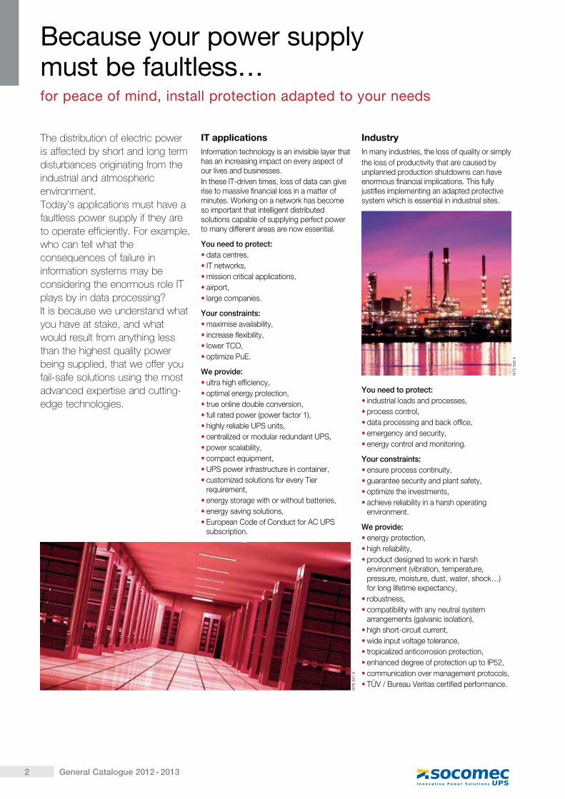
The distribution of electric power is affected by short and long term disturbances originating from the industrial and atmospheric environment.Today’s applications must have a faultless power supply if they are to operate efficiently. For example, who can tell what the consequences of failure in information systems may be considering the enormous role IT plays by in data processing?It is because we understand what you have at stake, and what would result from anything less than the highest quality power being supplied, that we offer you fail-safe solutions using the most advanced expertise and cutting-edge technologies.
IT applicationsInformation technology is an invisible layer that has an increasing impact on every aspect of our lives and businesses.In these IT-driven times, loss of data can give rise to massive financial loss in a matter of minutes. Working on a network has become so important that intelligent distributed solutions capable of supplying perfect power to many different areas are now essential.
You need to protect:� data centres,� IT networks,� mission critical applications,� airport,� large companies.
Your constraints:� maximise availability,� increase flexibility,� lower TCO,� optimize PuE.
We provide:� ultra high efficiency,� optimal energy protection,� true online double conversion,� full rated power (power factor 1),� highly reliable UPS units,� centralized or modular redundant UPS,� power scalability,� compact equipment,� UPS power infrastructure in container,� customized solutions for every Tier
requirement,� energy storage with or without batteries,� energy saving solutions,� European Code of Conduct for AC UPS
subscription.
IndustryIn many industries, the loss of quality or simplythe loss of productivity that are caused by unplanned production shutdowns can have enormous financial implications. This fully justifies implementing an adapted protective system which is essential in industrial sites.
You need to protect:� industrial loads and processes,� process control,� data processing and back office,� emergency and security,� energy control and monitoring.
Your constraints:� ensure process continuity,� guarantee security and plant safety,� optimize the investments,� achieve reliability in a harsh operating
environment.
We provide:� energy protection,� high reliability,� product designed to work in harsh
environment (vibration, temperature, pressure, moisture, dust, water, shock…) ����������� �������� �����
� robustness,� compatibility with any neutral system
arrangements (galvanic isolation),� high short-circuit current,� wide input voltage tolerance,� tropicalized anticorrosion protection,� enhanced degree of protection up to IP52,� communication over management protocols,� TÜV / Bureau Veritas certified performance.
Because your power supply ���������������� ������� ���������������� ����� ��������� �� ��������
SIT
E 6
21 A
SIT
E 5
58 A
3General Catalogue 2012 - 2013
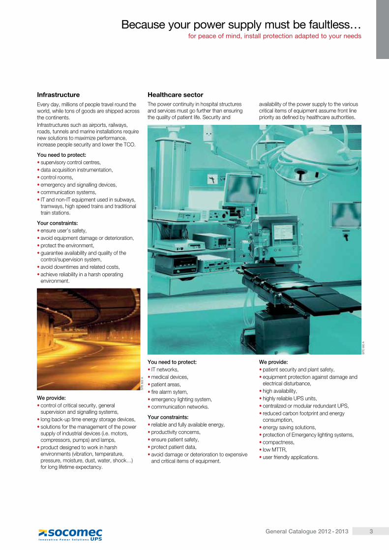
InfrastructureEvery day, millions of people travel round the world, while tons of goods are shipped across the continents.Infrastructures such as airports, railways, roads, tunnels and marine installations require new solutions to maximize performance, increase people security and lower the TCO.
You need to protect:� supervisory control centres,� data acquisition instrumentation,� control rooms,� emergency and signalling devices,� communication systems,� IT and non-IT equipment used in subways,
tramways, high speed trains and traditional train stations.
Your constraints:� ensure user’s safety,� avoid equipment damage or deterioration,� protect the environment,� guarantee availability and quality of the
control/supervision system,� avoid downtimes and related costs,� achieve reliability in a harsh operating
environment.
We provide:� control of critical security, general
supervision and signalling systems,� long back-up time energy storage devices,� solutions for the management of the power
supply of industrial devices (i.e. motors, compressors, pumps) and lamps,
� product designed to work in harsh environments (vibration, temperature, pressure, moisture, dust, water, shock…) ����������� �������� �����
�������� ���� ��������������������������� ������� ���������������� ����� ��������� �� ��������
The power continuity in hospital structures and services must go further than ensuring the quality of patient life. Security and
availability of the power supply to the various critical items of equipment assume front line priority as defined by healthcare authorities.
You need to protect:� IT networks,� medical devices,� patient areas,� fire alarm sytem,� emergency lighting system,� communication networks.
Your constraints:� reliable and fully available energy,� productivity concerns,� ensure patient safety,� protect patient data,� avoid damage or deterioration to expensive
and critical items of equipment.
We provide:� patient security and plant safety,� equipment protection against damage and
electrical disturbance,� high availability,� highly reliable UPS units,� centralized or modular redundant UPS,� reduced carbon footprint and energy
consumption,� energy saving solutions,� protection of Emergency lighting systems,� compactness,� low MTTR,� user friendly applications.
Healthcare sector
SIT
E 6
22 A
SIT
E 5
60 A
4 General Catalogue 2012 - 2013
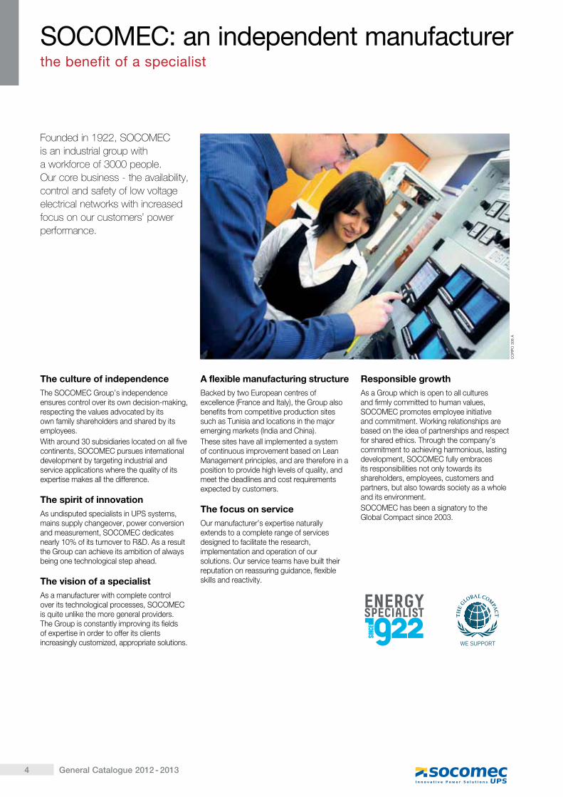
Founded in 1922, SOCOMEC is an industrial group with a workforce of 3000 people.Our core business - the availability, control and safety of low voltage electrical networks with increased focus on our customers’ power performance.
CO
RP
O 3
08 A
The culture of independenceThe SOCOMEC Group’s independence ensures control over its own decision-making, respecting the values advocated by its own family shareholders and shared by its employees.With around 30 subsidiaries located on all five continents, SOCOMEC pursues international development by targeting industrial and service applications where the quality of its expertise makes all the difference.
The spirit of innovationAs undisputed specialists in UPS systems, mains supply changeover, power conversion and measurement, SOCOMEC dedicates nearly 10% of its turnover to R&D. As a result the Group can achieve its ambition of always being one technological step ahead.
The vision of a specialistAs a manufacturer with complete control over its technological processes, SOCOMEC is quite unlike the more general providers. The Group is constantly improving its fields of expertise in order to offer its clients increasingly customized, appropriate solutions.
A flexible manufacturing structureBacked by two European centres of excellence (France and Italy), the Group also benefits from competitive production sites such as Tunisia and locations in the major emerging markets (India and China).These sites have all implemented a system of continuous improvement based on Lean Management principles, and are therefore in a position to provide high levels of quality, and meet the deadlines and cost requirements expected by customers.
The focus on serviceOur manufacturer’s expertise naturally extends to a complete range of services designed to facilitate the research, implementation and operation of our solutions. Our service teams have built their reputation on reassuring guidance, flexible skills and reactivity.
Responsible growthAs a Group which is open to all cultures and firmly committed to human values, SOCOMEC promotes employee initiative and commitment. Working relationships are based on the idea of partnerships and respect for shared ethics. Through the company’s commitment to achieving harmonious, lasting development, SOCOMEC fully embraces its responsibilities not only towards its shareholders, employees, customers and partners, but also towards society as a whole and its environment. SOCOMEC has been a signatory to the Global Compact since 2003.
������������������������������������������� �����������
5General Catalogue 2012 - 2013
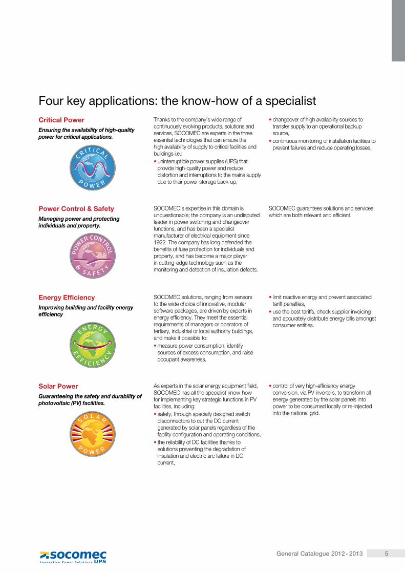
Power Control & SafetyManaging power and protecting individuals and property.
SOCOMEC’s expertise in this domain is unquestionable; the company is an undisputed leader in power switching and changeover functions, and has been a specialist manufacturer of electrical equipment since 1922. The company has long defended the benefits of fuse protection for individuals and property, and has become a major player in cutting-edge technology such as the monitoring and detection of insulation defects.
SOCOMEC guarantees solutions and services which are both relevant and efficient.
Critical PowerEnsuring the availability of high-quality power for critical applications.
Thanks to the company’s wide range of continuously evolving products, solutions and services, SOCOMEC are experts in the three essential technologies that can ensure the high availability of supply to critical facilities and buildings i.e.:� uninterruptible power supplies (UPS) that
provide high-quality power and reduce distortion and interruptions to the mains supply due to their power storage back-up,
� changeover of high availability sources to transfer supply to an operational backup source,
� continuous monitoring of installation facilities to prevent failures and reduce operating losses.
Energy EfficiencyImproving building and facility energy efficiency
SOCOMEC solutions, ranging from sensors to the wide choice of innovative, modular software packages, are driven by experts in energy efficiency. They meet the essential requirements of managers or operators of tertiary, industrial or local authority buildings, and make it possible to:� measure power consumption, identify
sources of excess consumption, and raise occupant awareness,
� limit reactive energy and prevent associated tariff penalties,
� use the best tariffs, check supplier invoicing and accurately distribute energy bills amongst consumer entities.
Solar PowerGuaranteeing the safety and durability of photovoltaic (PV) facilities.
As experts in the solar energy equipment field, SOCOMEC has all the specialist know-how for implementing key strategic functions in PV facilities, including:� safety, through specially designed switch
disconnectors to cut the DC current generated by solar panels regardless of the facility configuration and operating conditions,
� the reliability of DC facilities thanks to solutions preventing the degradation of insulation and electric arc failure in DC current,
� control of very high-efficiency energy conversion, via PV inverters, to transform all energy generated by the solar panels into power to be consumed locally or re-injected into the national grid.
! ���"���������� ��������"� �#� �� ������������
6 General Catalogue 2012 - 2013
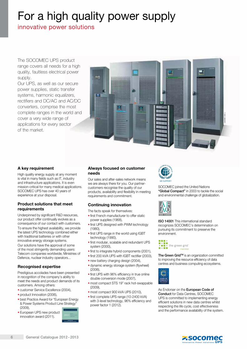
����������� ����������range covers all needs for a high quality, faultless electrical power supply.����� �������������������������power supplies, static transfer systems, harmonic equalizers, rectifiers and DC/AC and AC/DC converters, comprise the most complete ranges in the world and cover a very wide range of applications for every sector of the market.
! �����$��%������� ������������� &��&��� ����� ���� ���
A key requirementHigh quality energy supply at any moment is vital in many fields such as IT, industry and infrastructure applications. It is even mission-critical for many medical applications. SOCOMEC UPS has over 40 years of experience at your disposal.
Product solutions that meet requirementsUnderpinned by significant R&D resources, our product offer continually evolves as a consequence of our contact with customers.To ensure the highest availability, we provide the latest UPS technology combined either with traditional batteries or with other innovative energy storage systems.Our solutions have the approval of some of the most stringently demanding users: Telecom companies worldwide, Ministries of Defence, nuclear industry operators...
Recognised expertise Prestigious accolades have been presented in recognition of the company’s ability to meet the needs and product demands of its customers. Among others:� customer Service Excellence (2004),� product Innovation (2006),� ��� ���� ��������������������������
& Power Systems Product Line Strategy” (2009),
� European UPS new product innovation award (2011).
Always focused on customer needsOur sales and after-sales network means we are always there for you. Our partner-customers recognise the quality of our products, availability and flexibility in meeting requirements and commitment.
Continuing innovationThe facts speak for themselves:� first French manufacturer to offer static
power supplies (1968),� first UPS designed with PWM technology
(1980),� first UPS range in the world using IGBT
technology (1990),� first modular, scalable and redundant UPS
system (2000),� first to integrate hybrid components (2001),� first 200 kVA UPS with IGBT rectifier (2003),� new battery charging design (2004),� dynamic energy storage system (flywheel)
(2006),� first UPS with 96% efficiency in true online
double conversion mode (2007),� most compact STS 19” rack hot-swappable
(2009),� most compact 900 kVA UPS (2010),� first complete UPS range (10-2400 kVA)
with 3-level technology, 96% efficiency and power factor 1 (2012).
SOCOMEC joined the United Nations ������������ � in 2003 to tackle the social and environmental challenge of globalization.
ISO 14001 This international standard recognizes SOCOMEC’s determination on pursuing its commitment to preserve the environment.
The Green GridTM is an organization committed to improving the resource efficiency of data centres and business computing ecosystems.
As Endorser on the European Code of Conduct for Data Centres, SOCOMEC UPS is committed to implementing energy efficient solutions in new data centres whilst respecting the life cycle, cost effectiveness and the performance availability of the system.
GA
MM
E 0
08 U
7General Catalogue 2012 - 2013
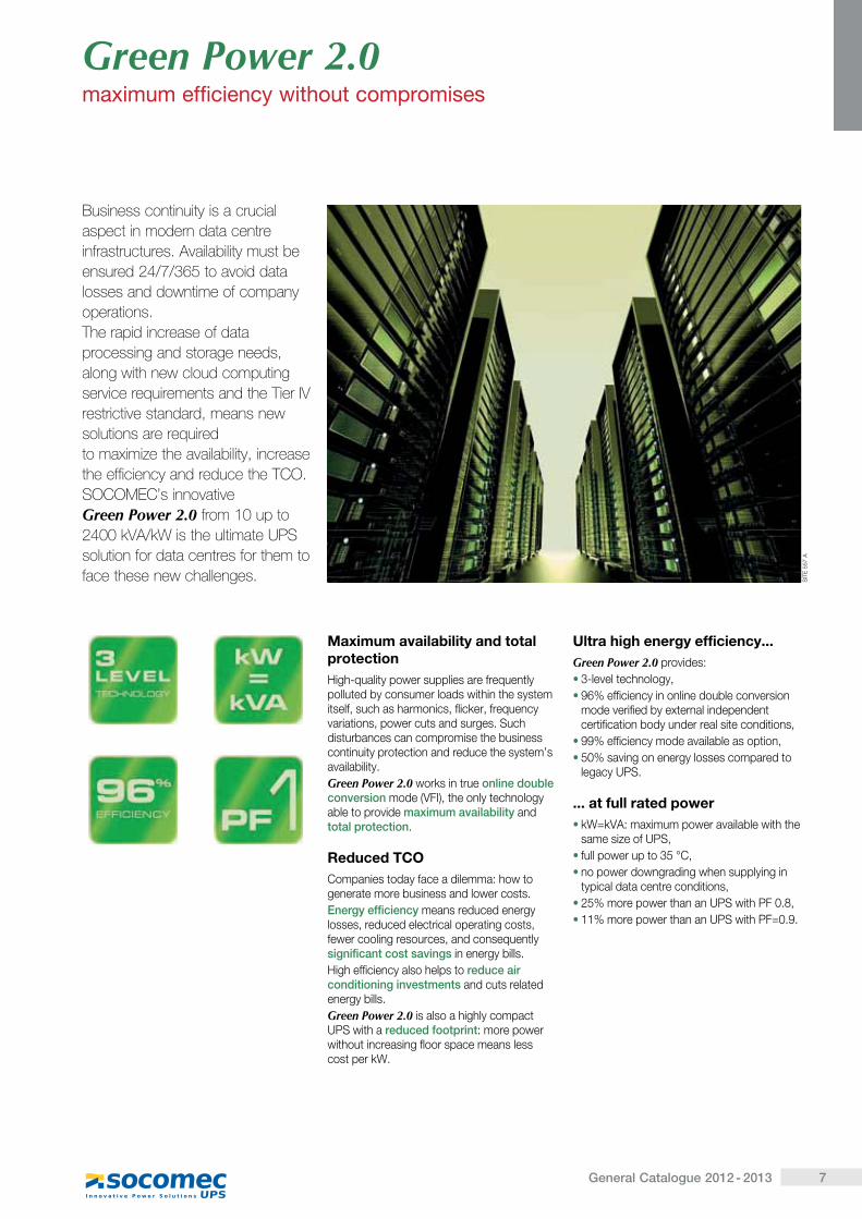
Business continuity is a crucial aspect in modern data centre infrastructures. Availability must be ensured 24/7/365 to avoid data losses and downtime of company operations.The rapid increase of data processing and storage needs, along with new cloud computing �����������������������������������!�restrictive standard, means new solutions are required to maximize the availability, increase the efficiency and reduce the TCO.SOCOMEC’s innovative Green Power 2.0 from 10 up to "#$$�%!&'%(������������������ ��solution for data centres for them to face these new challenges.
Maximum availability and total protectionHigh-quality power supplies are frequently polluted by consumer loads within the system itself, such as harmonics, flicker, frequency variations, power cuts and surges. Such disturbances can compromise the business continuity protection and reduce the system’s availability.Green Power 2.0 works in true online double conversion mode (VFI), the only technology able to provide ��������������� � and total protection.
Reduced TCOCompanies today face a dilemma: how to generate more business and lower costs.������������������means reduced energy losses, reduced electrical operating costs, fewer cooling resources, and consequently significant cost savings in energy bills.High efficiency also helps to reduce air ����� ������������ �� � and cuts related energy bills.Green Power 2.0 is also a highly compact UPS with a reduced footprint: more power without increasing floor space means less cost per kW.
Ultra high energy efficiency...Green Power 2.0 provides:� 3-level technology,� 96% efficiency in online double conversion
mode verified by external independent certification body under real site conditions,
� 99% efficiency mode available as option,� 50% saving on energy losses compared to
legacy UPS.
... at full rated power� kW=kVA: maximum power available with the
same size of UPS,� full power up to 35 °C,� no power downgrading when supplying in
typical data centre conditions,� 25% more power than an UPS with PF 0.8,� 11% more power than an UPS with PF=0.9.
Green Power 2.0�'������������������ ���� ��� �����
SIT
E 5
57 A

9General Catalogue 2012 - 2013
Single and three-phase UPS from 550 VA to 900 kVA
N TYS PLSingle-phase UPS550 and 750 VAp.10
N TYS PESingle-phase UPS600 to 2000 VAp.12
N TYS PRSingle-phase UPS1000 to 3000 VAp.14
N TYS PR rackSingle-phase UPS1000 to 1500 VA - Rack 1Up.16
N TYS RTSingle-phase UPS1100 to 11000 VAp.18
ITYSSingle-phase UPS1000 to 10000 VAp.22
MODULYS SystemSingle-phase UPS1.5 to 24 kVAp.24
MODULYS RMSingle-phase UPS1.5 to 9 kVAp.28
MODULYS TCSingle-phase UPS3 to 9 kVAp.30
MASTERYS BCSingle and three-phase UPS8 to 12 kVAp.32
BUSINESS CRITICALMASTERYS BCSingle and three-phase UPS15 to 120 kVAp.34DELPHYS BCThree-phase UPS160 to 200 kVAp.34
MODULYS Green PowerThree-phase UPS20 to 360 kVAp.36
Green Power 2.0MASTERYS GPThree-phase UPS10 to 120 kVAp.40DELPHYS GPThree-phase UPS160 to 400 kVAp.42
MASTERYS IP+Single and three-phase UPS10 to 80 kVAp.44
DELPHYS MP eliteThree-phase UPS80 to 200 kVAp.46
DELPHYS MXThree-phase UPS250 to 900 kVAp.48
CPSS EMergencyEmergency power supplies3 to 200 kVAp.50
Smart PowerPortUPS power infrastructure in containerfrom 100 kW to 2.4 MWp.56
10 General Catalogue 2012 - 2013
Sin
gle
-pha
se U
PS
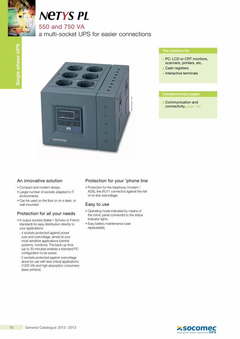
An innovative solution� Compact and modern design.� Larger number of sockets adapted to IT
environments.� Can be used on the floor or on a desk, or
wall-mounted.
Protection for all your needs� 6 output sockets (Italian / Schuko or French
standard) for easy distribution directly to your applications:- 4 sockets protected against power
cuts and overvoltage, aimed at your most sensitive applications (central systems, monitors). The back-up time (up to 30 minutes) enables a standard PC configuration to be saved.
- 2 sockets protected against overvoltage alone for use with less critical applications (1200 VA) and high absorption consumers (laser printers).
Protection for your ’phone line� Protection for the telephone /modem /
ADSL line (RJ11 connector) against the risk of on-line overvoltage.
Easy to use� Operating mode indicated by means of
the mimic panel connected to the status indicator lights.
� Easy battery maintenance (user replaceable).
N TYS PL550 and 750 VAa multi-socket UPS for easier connections
The solution for
> PC: LCD or CRT monitors, scanners, printers, etc.
> Cash registers> Interactive terminals
Complementary pages
> Communication and connectivity, page 102
NE
TYS
008
B 1
CA
T
11General Catalogue 2012 - 2013
N TYS PL 550 and 750 VA
Single-phase UPS
Technical data
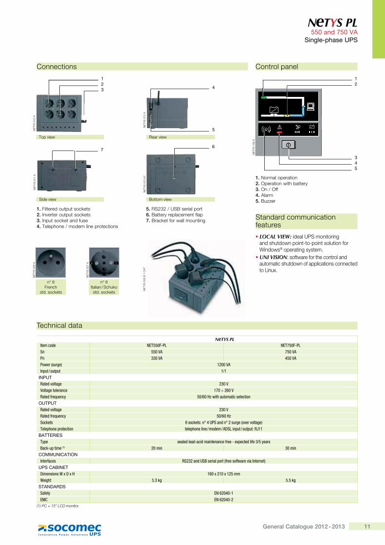
NeTYS PLItem code NET550F-PL NET750F-PLSn 550 VA 750 VAPn 330 VA 450 VAPower (surge) �������Input / output 1/1
INPUTRated voltage �����Voltage tolerance ��������Rated frequency �����������������������������
OUTPUTRated voltage 230 VRated frequency ������Sockets ����������!�"#$%��&�!����'*�,�:�':����*�;<���=����='�������� ����=�����������&����>%?��=������=���@J��
BATTERIESType �����&���&Q���&�����������Z'��Q�[=����&��Z��� \��'�]���Q�=����(1) ����� �����
COMMUNICATIONInterfaces @%�����&#%]��'���=�'�,Z'����Z���'�:��^���'���;
UPS CABINET>���������_[>[� ���[���[�� ��_��*�� 5.3 kg 5.5 kg
STANDARDSSafety EN 62040-1EMC EN 62040-2
������������� ���������
Connections
1. Filtered output sockets2. Inverter output sockets3. Input socket and fuse4. Telephone / modem line protections
5. RS232 / USB serial port6. Battery replacement flap7. Bracket for wall mounting Standard communication
features
� LOCAL VIEW: ideal UPS monitoring and shutdown point-to-point solution for Windows® operating system.
� UNI VISION: software for the control and automatic shutdown of applications connected to Linux.
Control panel
1. Normal operation2. Operation with battery3. On / Off4. Alarm5. Buzzer
NE
TYS
109
A
2
345
1
NE
TYS
035
B 1
CA
T
NE
TYS
028
A
���! French
std. sockets
NE
TYS
027
A
���!Italian / Schuko std. sockets
Top view
NE
TYS
010
A
21
3
Bottom view
NE
TYS
013
A7
6
Side view
NE
TYS
011
A
7
Rear view
NE
TYS
012
A
4
5
12 General Catalogue 2012 - 2013
Sin
gle
-pha
se U
PS
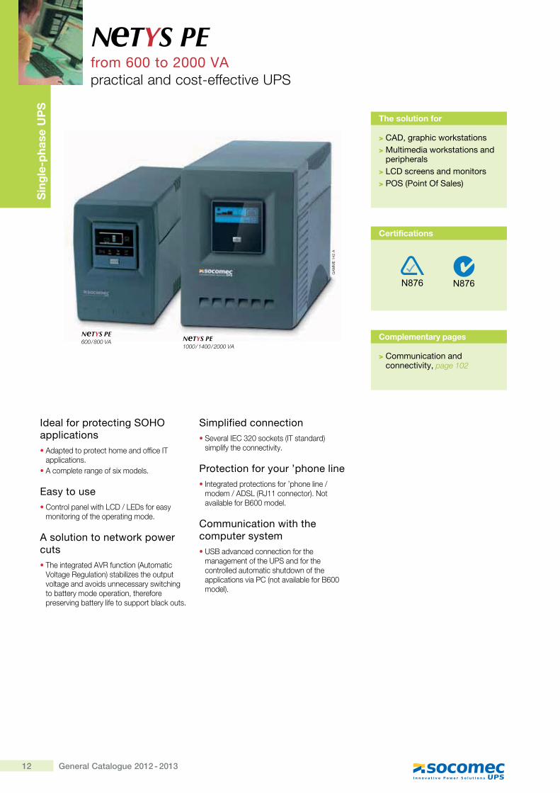
Ideal for protecting SOHO applications� Adapted to protect home and office IT
applications.� A complete range of six models.
Easy to use� Control panel with LCD / LEDs for easy
monitoring of the operating mode.
A solution to network power cuts� The integrated AVR function (Automatic
Voltage Regulation) stabilizes the output voltage and avoids unnecessary switching to battery mode operation, therefore preserving battery life to support black outs.
Simplified connection� Several IEC 320 sockets (IT standard)
simplify the connectivity.
Protection for your ’phone line� Integrated protections for ’phone line /
modem / ADSL (RJ11 connector). Not available for B600 model.
Communication with the computer system� USB advanced connection for the
management of the UPS and for the controlled automatic shutdown of the applications via PC (not available for B600 model).
N TYS PEfrom 600 to 2000 VApractical and cost-effective UPS
The solution for
> CAD, graphic workstations> Multimedia workstations and
peripherals> LCD screens and monitors> POS (Point Of Sales)
Complementary pages
> Communication and connectivity, page 102
GA
MM
E 1
42 A
NeTYS PE600 / 800 VA NeTYS PE
1000 / 1400 / 2000 VA
Certifications
13General Catalogue 2012 - 2013
N TYS PE from 600 to 2000 VA
Single-phase UPS
Technical data
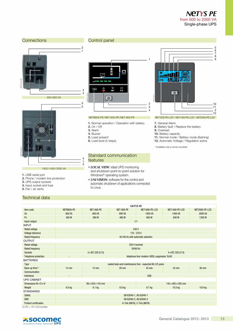
NeTYS PEItem code NETB600-PE NET-600-PE NET-800-PE NET1000-PE-LCD NET1400-PE-LCD NET2000-PE-LCDSn 600 VA 600 VA 800 VA 1000 VA 1400 VA 2000 VAPn 360 W 360 W 480 W 600 W 840 W 1200 WInput / output 1/1
INPUTRated voltage 230 VVoltage tolerance 170 - 270 VRated frequency �����������������������������
OUTPUTRated voltage �����������Rated frequency �������%������ 3 x IEC 320 (C13) 4 x IEC 320 (C13)<���=����='�������� - ����=�����������&����>%?��=='����'�@J"
BATTERIESType �����&���&Q���&�����������Z'��Q�[=����&��Z��� \��'�]���Q�=���� (1) � ��� � ��� ����� " ��� ��� �����`������������^���'Z���� - USB
UPS CABINET>���������_[>[� 99 x 334 x 143 mm 145 x 405 x 205 mm_��*�� 6.0 kg 6.1 kg 6.6 kg 9.7 kg 10.5 kg 10.6 kg
STANDARDSSafety EN 62040-1, AS 62040-1EMC EN 62040-2, AS 62040-2$'�&�����'��Z������� �Q<���,hj�;z`Q<���,hj�;
������������� ���������
Connections
1. USB serial port2. Phone / modem line protection3. UPS output sockets4. Input socket and fuse5. Fan / air vents
600 / 800 VA
"###$"'##$*###�+�
NE
TYS
015
B
12
43
NE
TYS
082
A
41
52
3
NETB600-PE / NET-600-PE / NET-800-PE
Control panel
1. Normal operation / Operation with battery2. On / Off3. Alarm4. Buzzer5. Load present6. Load level (5 steps)
7. General Alarm8. Battery fault / Replace the battery9. Overload10. Battery capacity11. Normal mode / Battery mode (flashing)12. Automatic Voltage / Regulation active
NE
TYS
102
A
1
234
NE
TYS
103
A
112
765
98
10
12
NET1000-PE-LCD* / NET1400-PE-LCD* / NET2000-PE-LCD*
Standard communication features
� LOCAL VIEW: ideal UPS monitoring and shutdown point-to-point solution for Windows® operating system.
� UNI VISION: software for the control and automatic shutdown of applications connected to Linux.
����������������������������������
14 General Catalogue 2012 - 2013
Sin
gle
-pha
se U
PS
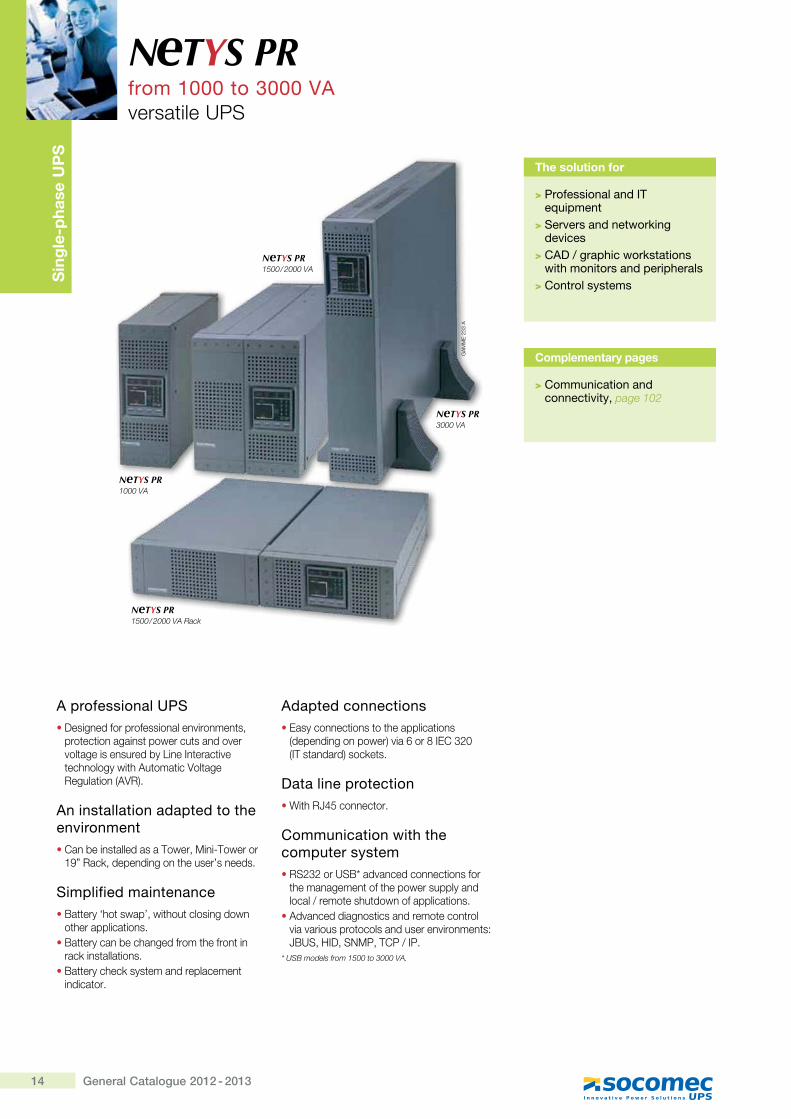
A professional UPS� Designed for professional environments,
protection against power cuts and over voltage is ensured by Line Interactive technology with Automatic Voltage Regulation (AVR).
An installation adapted to the environment� Can be installed as a Tower, Mini-Tower or
19” Rack, depending on the user’s needs.
Simplified maintenance� Battery ‘hot swap’, without closing down
other applications.� Battery can be changed from the front in
rack installations.� Battery check system and replacement
indicator.
Adapted connections� Easy connections to the applications
(depending on power) via 6 or 8 IEC 320 >?@�� ������K���Q� ��
Data line protection� With RJ45 connector.
Communication with the computer system� RS232 or USB* advanced connections for
the management of the power supply and local / remote shutdown of applications.
� Advanced diagnostics and remote control via various protocols and user environments: JBUS, HID, SNMP, TCP / IP.
* USB models from 1500 to 3000 VA.
N TYS PRfrom 1000 to 3000 VAversatile UPS
The solution for
> Professional and IT equipment
> Servers and networking devices
> CAD / graphic workstations with monitors and peripherals
> Control systems
Complementary pages
> Communication and connectivity, page 102
NeTYS PR1500 / 2000 VA Rack
GA
MM
E 2
33 A
NeTYS PR3000 VA
NeTYS PR1500 / 2000 VA
NeTYS PR1000 VA
15General Catalogue 2012 - 2013
N TYS PR from 1000 to 3000 VA
Single-phase UPS
Technical data
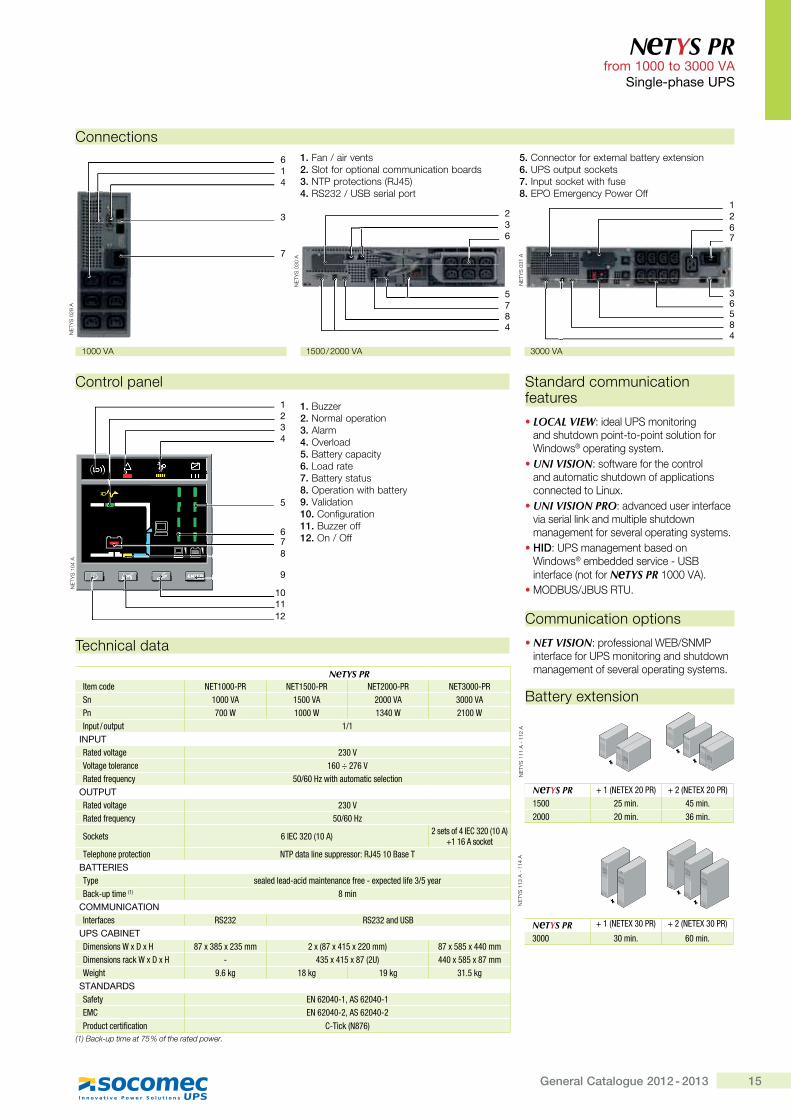
NeTYS PRItem code NET1000-PR NET1500-PR NET2000-PR NET3000-PRSn 1000 VA 1500 VA 2000 VA 3000 VAPn 700 W 1000 W 1340 W 2100 WInput / output 1/1
INPUTRated voltage �����Voltage tolerance 160 ÷ 276 VRated frequency �����������������������������
OUTPUTRated voltage 230 VRated frequency ������
%������ 6 IEC 320 (10 A) ������Z"^{`���,���;|����������
<���=����='�������� h<$&���������=='����'�@J" ��]���<BATTERIESType �����&���&Q���&�����������Z'��Q�[=����&��Z��� \��']���Q�=����(1) j���
COMMUNICATION^���'Z���� RS232 @%�����&#%]
UPS CABINET>���������_[>[� j[�j [�� �� �[,j["� [�����; j[ j [""���>���������'���_[>[� - "� ["� [j,�#; ""�[ j [j��_��*�� 9.6 kg 18 kg 19 kg 31.5 kg
STANDARDSSafety EN 62040-1, AS 62040-1EMC EN 62040-2, AS 62040-2$'�&�����'��Z������� `Q<���,hj�;
(1) Back-up time at 75 % of the rated power.
Connections1. Fan / air vents2. Slot for optional communication boards3. NTP protections (RJ45)4. RS232 / USB serial port
5. Connector for external battery extension6. UPS output sockets7. Input socket with fuse8. EPO Emergency Power Off
Control panel
1. Buzzer2. Normal operation3. Alarm4. Overload5. Battery capacity6. Load rate7. Battery status8. Operation with battery 9. Validation 10. Configuration11. Buzzer off12. On / Off
Standard communication features
� LOCAL VIEW: ideal UPS monitoring and shutdown point-to-point solution for Windows® operating system.
� UNI VISION: software for the control and automatic shutdown of applications connected to Linux.
� UNI VISION PRO: advanced user interface via serial link and multiple shutdown management for several operating systems.
� HID: UPS management based on Windows® embedded service - USB interface (not for N TYS PR 1000 VA).
� MODBUS/JBUS RTU.
Communication options
� NET VISION: professional WEB/SNMP interface for UPS monitoring and shutdown management of several operating systems.
1000 VA
Battery extension
NE
TYS
111
A -
112
A
NeTYS PR + 1 (NETEX 20 PR) + 2 (NETEX 20 PR)1500 � ���} " ���}2000 �����} �����}
NE
TYS
113
A -
114
A
NeTYS PR + 1 (NETEX 30 PR) + 2 (NETEX 30 PR)
3000 �����} �����}
NE
TYS
104
A
4
101112
32
8
5
6
1
9
7
NE
TYS
029
A
3
41
7
6
1500 / 2000 VA
NE
TYS
030
A
2
63
5784
3000 VA
NE
TYS
031
A
1
62
6584
7
3
16 General Catalogue 2012 - 2013
Sin
gle
-pha
se U
PS
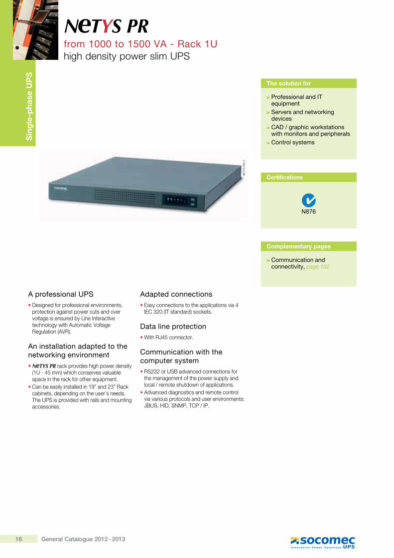
A professional UPS� Designed for professional environments,
protection against power cuts and over voltage is ensured by Line Interactive technology with Automatic Voltage Regulation (AVR).
An installation adapted to the networking environment� N TYS PR rack provides high power density
(1U - 45 mm) which conserves valuable space in the rack for other equipment.
� Can be easily installed in 19” and 23” Rack cabinets, depending on the user’s needs. The UPS is provided with rails and mounting accessories.
Adapted connections� Easy connections to the applications via 4
IEC 320 (IT standard) sockets.
Data line protection� With RJ45 connector.
Communication with the computer system� RS232 or USB advanced connections for
the management of the power supply and local / remote shutdown of applications.
� Advanced diagnostics and remote control via various protocols and user environments: JBUS, HID, SNMP, TCP / IP.
N TYS PRfrom 1000 to 1500 VA - Rack 1Uhigh density power slim UPS
The solution for
> Professional and IT equipment
> Servers and networking devices
> CAD / graphic workstations with monitors and peripherals
> Control systems
Complementary pages
> Communication and connectivity, page 102
NE
TYS
090
A
Certifications
17General Catalogue 2012 - 2013
N TYS PR from 1000 to 1500 VA - Rack 1U
Single-phase UPS
Technical data
N TYS PR RACKItem code NET1000-PR-1U NET1500-PR-1USn 1000 VA 1500 VAPn 670 W 1000 WInput / output 1/1
INPUTRated voltage 230 V (default), 220 V, 230 V, 240 V selectableRated frequency �����������Q������*
OUTPUTRated voltage 230 VRated frequency ������Sockets 4 x IEC 320 (10 A)<���=����='�������� h<$&���������=='����'�@J" ��]���<
BATTERIESType �����&���&Q���&�����������Z'��Q�[=����&��Z��� \��'�]���Q�=����(1) �����
COMMUNICATIONInterfaces @%���Q#%]
UPS CABINET>���������_[>[� 440 x 578 x 44.5 mm_��*�� 21 kg 23 kg
STANDARDSSafety EN 62040-1, AS 62040-1EMC EN 62040-2, AS 62040-2$'�&�����'��Z������� `Q<���,hj�;
(1) Back-up time at 75 % of the rated power.
Standard communication features
� LOCAL VIEW: ideal UPS monitoring and shutdown point-to-point solution for Windows® operating system.
� UNI VISION: software for the control and automatic shutdown of applications connected to Linux.
� UNI VISION PRO: advanced user interface via serial link and multiple shutdown management for several operating systems.
� HID: UPS management based on Windows® embedded service - USB interface.
� MODBUS/JBUS RTU.
Communication options
� NET VISION: professional WEB/SNMP interface for UPS monitoring and shutdown management of several operating systems.
� Dry-contact interface.
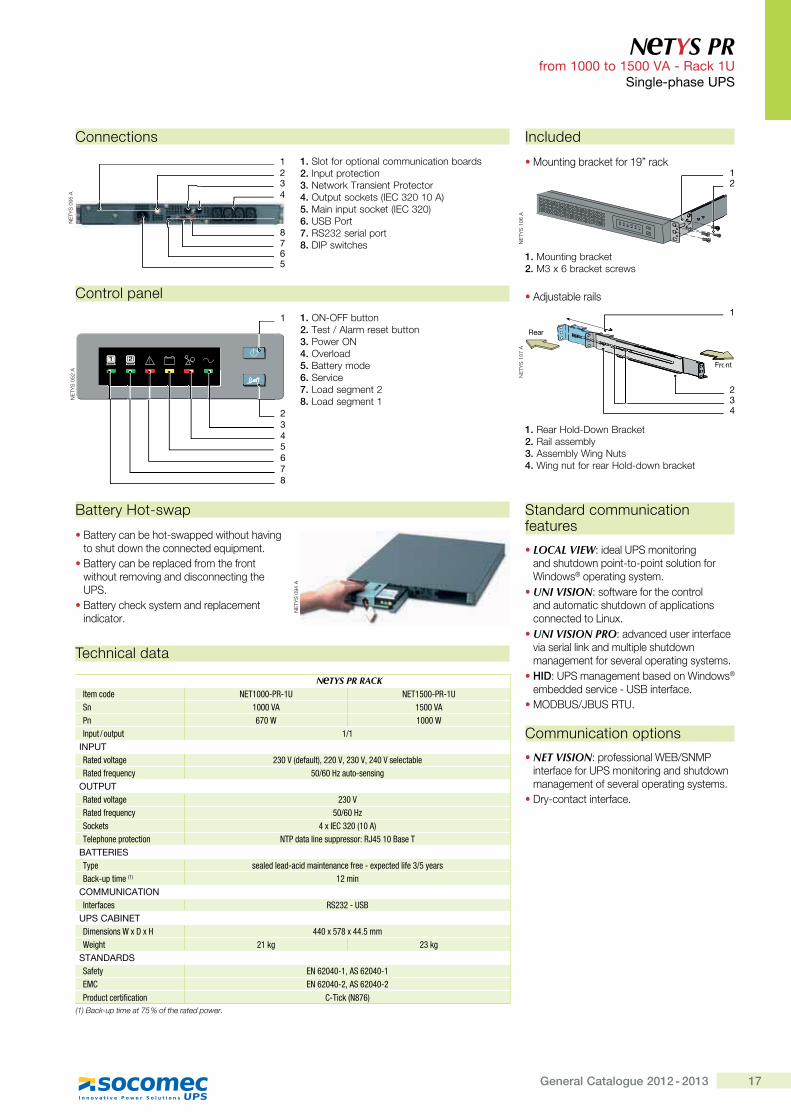
Connections
1. Slot for optional communication boards2. Input protection3. Network Transient Protector4. Output sockets (IEC 320 10 A)5. Main input socket (IEC 320)6. USB Port7. RS232 serial port8. DIP switches
1
5
NE
TYS
095
A
2
43
876
NE
TYS
052
A
Control panel
1. ON-OFF button2. Test / Alarm reset button3. Power ON 4. Overload 5. Battery mode 6. Service 7. Load segment 2 8. Load segment 1
1
567
234
8
NE
TYS
094
A
Battery Hot-swap
� Battery can be hot-swapped without having to shut down the connected equipment.
� Battery can be replaced from the front without removing and disconnecting the UPS.
� Battery check system and replacement indicator.
Included
� Mounting bracket for 19” rack
1. Mounting bracket2. M3 x 6 bracket screws
� Adjustable rails
1. Rear Hold-Down Bracket2. Rail assembly3. Assembly Wing Nuts4. Wing nut for rear Hold-down bracket
NE
TYS
106
A
12
NE
TYS
107
A
1
Rear
Front
4
ooFro
32
18 General Catalogue 2012 - 2013
Sin
gle
-pha
se U
PS
Simple to install
� IEC input and output connections >""##XZ###�+�K�� ����������� ����� �� ������ ������ [���� X������ � [��������� ��� �[>\###X""###+�K�
�]����� ��� ���� ������ ���� ��������Q������ ��
�� ��� �^�������
Easy to use
�_��������� ������������������ � �� ���� ������������������ ������ ��������
�� ��� ����� �{�_�� ���Q���|������}������� ~�� ���>|}~K�
�]����{���� �������� [������� [� ������� ��������� � [������ ��� � ���� [���~��^������������������ �����>""##XZ###+�K�
�{]���������� [�����^���������!�������>\###X""###+�K�
Meets practical needs
����������������^������ ��[������� [������������^������������ ������ ����� ������ ������������$ � [������������������������������������� �� ����� [�� ��� ��
�}�������� ����� ������>�|}K ���� ������QX�� ������������� ���^���� ����� ���� ����
���������� ���"�"���������������� �������� ��� ��������� [��^�������� ������ ����� ��� �����^���� [��^�� �������������Q����>\###X""###+�K�
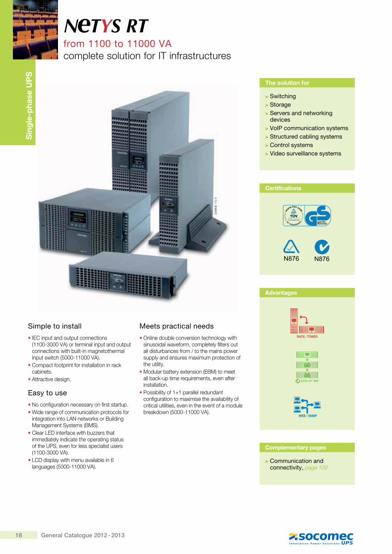
N TYS RTfrom 1100 to 11000 VA������ ����� ������?@������ ��� ����
The solution for
>���������$>��� �$�>�����&����������� �"��$�
��&����>�* +;�� �������� ���������>�����������������$��������>�� ��� ���������>�*��� ����&���������������
��
}}
�"
"#�
Advantages
Complementary pages
>��� �������� ������ ������&�����page 102
Certifications
19General Catalogue 2012 - 2013
N TYS RT from 1100 to 11000 VA
���$��#�����<;�
@��[������� �
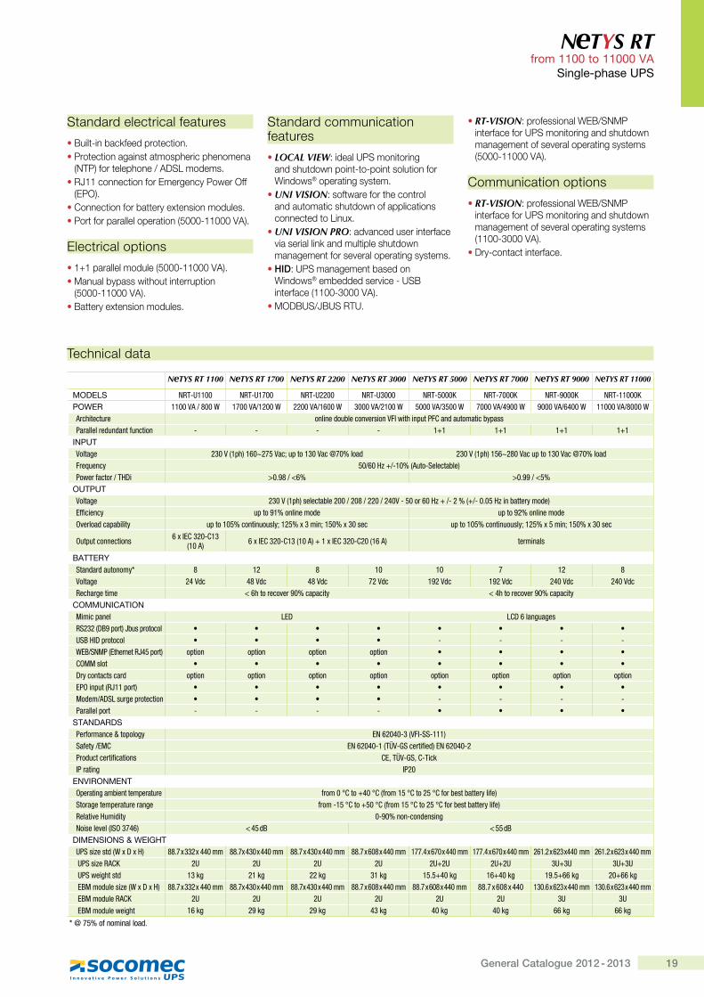
NeTYS RT 1100 NeTYS RT 1700 NeTYS RT 2200 NeTYS RT 3000 NeTYS RT 5000 NeTYS RT 7000 NeTYS RT 9000 NeTYS RT 11000
MODELS NRT-U1100 NRT-U1700 NRT-U2200 NRT-U3000 NRT-5000K NRT-7000K NRT-9000K NRT-11000K;�=�> 1100 VA / 800 W 1700 VA/1200 W 2200 VA/1600 W 3000 VA/2100 W 5000 VA/3500 W 7000 VA/4900 W 9000 VA/6400 W 11000 VA/8000 WArchitecture online double conversion VFI with input PFC and automatic bypassParallel redundant function - - - - 1+1 1+1 1+1 1+1
+?;<@Voltage 230 V (1ph) 160~275 Vac; up to 130 Vac @70% load 230 V (1ph) 156~280 Vac up to 130 Vac @70% loadFrequency 50/60 Hz +/-10% (Auto-Selectable)Power factor / THDi >0.98 / <6% >0.99 / <5%
�<@;<@Voltage 230 V (1ph) selectable 200 / 208 / 220 / 240V - 50 or 60 Hz + /- 2 % (+/- 0.05 Hz in battery mode)Efficiency up to 91% online mode up to 92% online modeOverload capability up to 105% continuously; 125% x 3 min; 150% x 30 sec up to 105% continuously; 125% x 5 min; 150% x 30 sec
Output connections 6 x IEC 320-C13 (10 A) 6 x IEC 320-C13 (10 A) + 1 x IEC 320-C20 (16 A) terminals
�J@@�>KStandard autonomy* 8 12 8 10 10 7 12 8Voltage 24 Vdc 48 Vdc 48 Vdc 72 Vdc 192 Vdc 192 Vdc 240 Vdc 240 VdcRecharge time < 6h to recover 90% capacity < 4h to recover 90% capacity
����<?+�J@+�?Mimic panel LED LCD 6 languagesRS232 (DB9 port) Jbus protocol � � � � � � � �USB HID protocol � � � � - - - -WEB/SNMP (Ethernet RJ45 port) option option option option � � � �COMM slot � � � � � � � �Dry contacts card option option option option option option option option EPO input (RJ11 port) � � � � � � � �Modem/ADSL surge protection � � � � - - - -Parallel port - - - - � � � �
�@J?QJ>Q�Performance & topology EN 62040-3 (VFI-SS-111)Safety /EMC EN 62040-1 (TÜV-GS certified) EN 62040-2Product certifications CE, TÜV-GS, C-TickIP rating IP20
�?*+>�?��?@Operating ambient temperature from 0 °C to +40 °C (from 15 °C to 25 °C for best battery life)Storage temperature range from -15 °C to +50 °C (from 15 °C to 25 °C for best battery life)Relative Humidity 0-90% non-condensingNoise level (ISO 3746) < 45 dB < 55 dB
Q+��?�+�?��W�=�+XY@UPS size std (W x D x H) 88.7 x 332 x 440 mm 88.7x 430 x 440 mm 88.7 x 430 x 440 mm 88.7 x 608 x 440 mm 177.4 x 670 x 440 mm 177.4 x 670 x 440 mm 261.2 x 623 x440 mm 261.2 x 623 x 440 mm UPS size RACK 2U 2U 2U 2U 2U+2U 2U+2U 3U+3U 3U+3U UPS weight std 13 kg 21 kg 22 kg 31 kg 15.5+40 kg 16+40 kg 19.5+66 kg 20+66 kg EBM module size (W x D x H) 88.7 x 332 x 440 mm 88.7x 430 x 440 mm 88.7x 430 x 440 mm 88.7 x 608 x 440 mm 88.7 x 608 x 440 mm 88.7 x 608 x 440 130.6 x 623 x 440 mm 130.6 x 623 x 440 mm EBM module RACK 2U 2U 2U 2U 2U 2U 3U 3U EBM module weight 16 kg 29 kg 29 kg 43 kg 40 kg 40 kg 66 kg 66 kg
* @ 75% of nominal load.
~ ���������� �������� ����
�|��� X�����Q������� �� �������� �� �������� � ����[�����[�������
>_@�K��� ����[���$��~{����������""������ ����������������������
>���K��]����� �������� ����� ������������������ ���������������� ���>\###X""###+�K�
���� ������� ����
�"�"��������������>\###X""###+�K��}������������� [�� �� ����� ���
>\###X""###+�K��|� ����� ��������������
~ ��������������� ������ ����
� LOCAL VIEW��������~���� ��������[� �������� X �X���� ���� ������Windows®����� ����� ���
� UNI VISION���� ������� [���� �������� ��� ���[� ������������� ���������� �� �{�����
� UNI VISION PRO���^����������� ������^�����������Q������ �����[� ������������ �����^��������� ����� ����
� HID���~�������� �������Windows®�����������^���X�~|�� ������>""##XZ###+�K�
�}��|�~$�|�~�@��
� RT-VISION�������������`�|$~_}��� �����������~���� ��������[� ������������ ����^��������� ����� ���>\###X""###+�K�
]�������� ����� ����
� RT-VISION�������������`�|$~_}��� �����������~���� ��������[� ������������ ����^��������� ����� ���>""##XZ###+�K�
����X��� �� �� �������
20 General Catalogue 2012 - 2013
N TYS RT from 1100 to 11000 VA ���$��#�����<;�
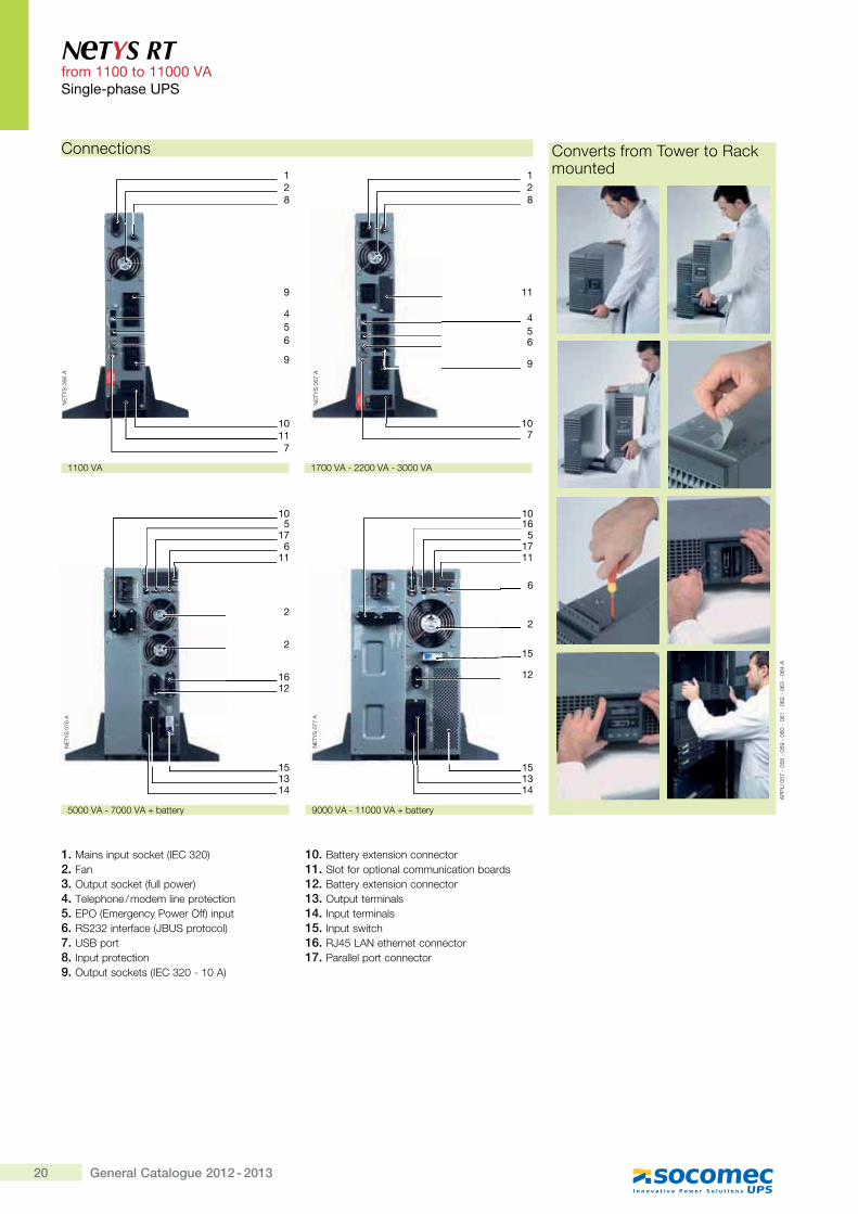
Connections
1. }�������� ���Q� >?�]Z*#K2. Fan3. �� �� ���Q� >���������K4. @����[���$������������ �� ���5. ���>����������������K���� 6. �~*Z*�� ������>�|�~��� ����K7. �~|��� 8. ?��� ��� �� ���9. �� �� ���Q� �>?�]Z*#X"#�K
10. |� ����� ������������ ��11. ~�� ����� �������������� ���������12. |� ����� ������������ ��13. �� �� ��������14. ?��� ��������15. Input switch16. ��'\{�_� [���� ������ ��17. ����������� ������ ��
_�
@�~
#��
�
_�
@�~
#!!
�
28
1
1011
7
9
9
456
_�
@�~
#�!
�
1314
2
116
175
10
15
1612
2
1314
1117
51610
15
15
12
2
6
""##+�
�###+�X""###+����� ���\###+�X�###+����� ���
��
�{?
#\�
X#
\�X
#\�
X#
!#X
#!"
X#
!*X
#!Z
X#
!'�
]��^�� �����@���� ����Q���� ��
"�##+�X**##+�XZ###+�
_�
@�~
#!�
�
28
1
107
11
456
9
21General Catalogue 2012 - 2013
N TYS RT from 1100 to 11000 VA
���$��#�����<;�
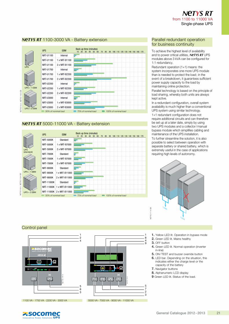
10 20 30 40 50 60 70 80 90 100 110 120 130 140 150 160 170UPS EBM Back up time (minutes)
NRT-5000K Standard
NRT-5000K 1 x NRT-B7000
NRT-5000K 2 x NRT-B7000
NRT-7000K Standard
NRT-7000K 1 x NRT-B7000
NRT-7000K 2 x NRT-B7000
NRT-9000K Standard
NRT-9000K 1 x NRT-B11000
NRT-9000K 2 x NRT-B11000
NRT-11000K Standard
NRT-11000K 1 x NRT-B11000
NRT-11000K 2 x NRT-B1100050% of nominal load 75% of nominal load 100% of nominal load
50% of nominal load 75% of nominal load 100% of nominal load
UPS EBMBack up time (minutes)10 20 30 40 50 60 70 80 90 100 110 120 130 140 150 160 170
NRT-U1100 Internal
NRT-U1100 1 x NRT-B1100
NRT-U1100 2 x NRT-B1100
NRT-U1700 Internal
NRT-U1700 1 x NRT-B2200
NRT-U1700 2 x NRT-B2200
NRT-U2200 Internal
NRT-U2200 1 x NRT-B2200
NRT-U2200 2 x NRT-B2200
NRT-U3000 Internal
NRT-U3000 1 x NRT-B3000
NRT-U3000 2 x NRT-B3000
UPS + 1 EBM
UPS + 2 EBM
UPS (standard)
_�
@�~
""\
�X
_�
@�~
""�
��
|
UPS + 1 EBM
UPS + 2 EBM
UPS
N TYS RT""##XZ###+�X|� ����� ������
N TYS RT\###X""###+�X|� ����� ������
_�
@�~
""!
�X
_�
@�~
""�
��
|
]�� ��������
1. ������{���� ������ ���������������2. �����{���� �}����[��� [�3. OFF button4. �����{���� �_���������� ���>��^�� ��
��X����K5. �_$@�~@����������^�������� ��6. {���������������� [��� �� ���� [��
������ ���� [�� [��[�����^���� [������� ��� [��� ���
7. _�^�� ���� ���8. ���[��������{]��������9 �����{���� �~ � ���� [������
_�
@�~
"#�
�
42
5
~"
#��
~
6
~~_
�@�@@
~
3
1
_�
@�~
""#
�
57
"#�
""
2
"_
�@�@@
~"
3
481
Load
Load
���������������� ����� ��� �������������� ���� �
@���[��^� [�[�[�� ��^�����^�������� ���� ��������� ����� ��� ����N TYS RT ��~����������^�ZQ+������������������"�"������������������� ����� ���>"�"K������ [���� ����������� �����������~������ [���������� ���� �� [�������� [��^�� �������Q������ ����� ������������ ����������������� � � [����������� �������������� �� ������������ ��[�������������� [�����������������[������[������� [��� ����������Q�� �� �^��?���������� �������� �����^�������� ���^�������� ������[[�[�� [������^�� �������~��� ������������� ��[������"�"�������� �������� ��������� ����������� ����������� ������� [����������� ��� ��� ���� �������������� ����~����������������� ��$�������������������[��[����������������������� �������� [���~��� ���� ����@���� [��� �������� [����� ����� �������������� ������ �� ��������� ����� [������ ��� ������[������ �����[��[���� �������������� [�������������� ������������[�[��^������� ������
9
_�
@�~
""�
��
|
\###+�X�###+�X�###+�X""###+�""##+�X"�##+�X**##+�XZ###+�
22 General Catalogue 2012 - 2013
Sin
gle
-pha
se U
PS
High protection and high availability� Online double conversion technology (VFI)
and sinusoidal absorption compatible with all IT and industrial applications, operating environments and when used in conjunction with a generator set.
� Permanent regulation of output voltage and frequency.
� Wide tolerance of the input voltage limits the number of switchovers to battery mode, prolonging the battery life.
� The automatic bypass takes over immediately in the event of overloads or faults, ensuring continuous power supply to the loads.
Simple to install and easy to use� The UPS comes ready for power up with the
internal batteries connected and fully charged. The auto restart function to restart even in the event of prolonged power failure.
� No special plant preparation required thanks to the built-in magneto-thermal protection.
� The power distribution graphic display shows at-a-glance if the system is working correctly or not. Battery health can be checked either via the control panel or using a remote PC.
Operating efficiency and versatility� The standard configuration and the
communication accessories can easily be adapted to a wide range of operating environments.
� The manual bypass means that on site periodic and / or emergency maintenance can be performed on the 6 and 10 kVA models without having to disconnect the loads.
� The communication software can be used to program scheduled start-up and shutdown where automatic power management procedures are required.
Standard communication features� LOCAL VIEW: ideal UPS monitoring
and shutdown point-to-point solution for Windows® operating system.
� UNI VISION: software for the control and automatic shutdown of applications connected to Linux.
� UNI VISION PRO: advanced user interface via serial link and multiple shutdown management for several operating systems.
� MODBUS/JBUS RTU.
Communication options� NET VISION: professional WEB/SNMP
interface for UPS monitoring and shutdown management of several operating systems.
� Dry-contact interface.
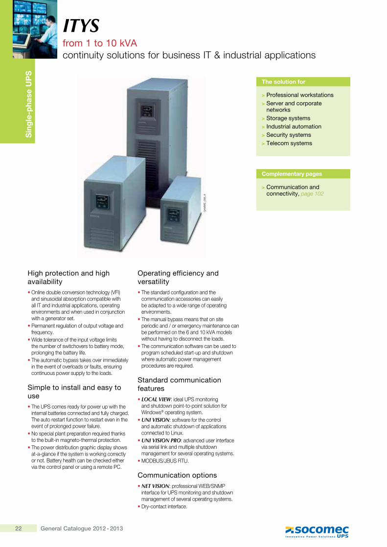
ITYSfrom 1 to 10 kVAcontinuity solutions for business IT & industrial applications
The solution for
> Professional workstations> Server and corporate
networks> Storage systems> Industrial automation> Security systems> Telecom systems
GA
MM
E_0
66_A
Complementary pages
> Communication and connectivity, page 102
23General Catalogue 2012 - 2013
ITYS from 1 to 10 kVA
Single-phase UPS
Technical data
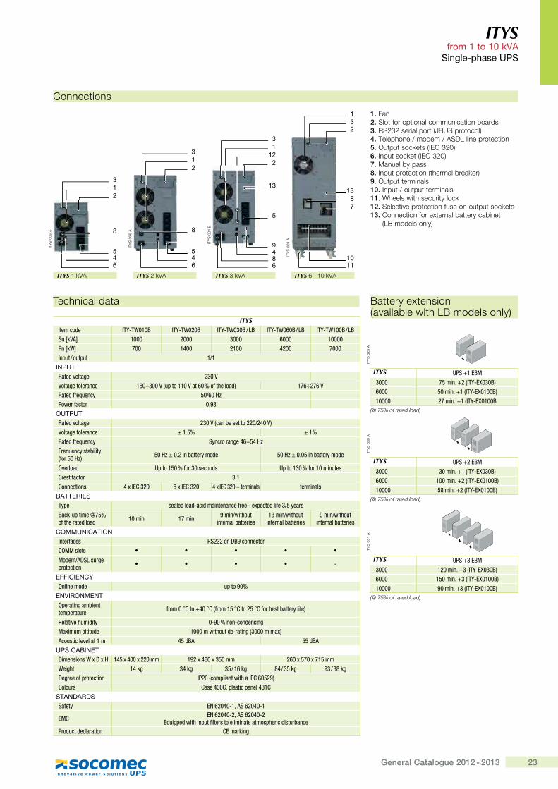
ITYSItem code ITY-TW010B ITY-TW020B ITY-TW030B / LB ITY-TW060B / LB ITY-TW100B / LBSn [kVA] 1000 2000 3000 6000 10000Pn [kW] 700 1400 2100 4200 7000Input / output 1/1
INPUTRated voltage 230 VVoltage tolerance 160÷300 V (up to 110 V at 60 % of the load) 176÷276 VRated frequency 50/60 HzPower factor 0,98
OUTPUTRated voltage 230 V (can be set to 220/240 V)Voltage tolerance ± 1.5% ± 1%Rated frequency Syncro range 46÷54 Hz
Frequency stability ,Z�'� ���; 50 Hz ± 0.2 in battery mode 50 Hz ± 0.05 in battery mode
Overload Up to 150 % for 30 seconds Up to 130 % for 10 minutesCrest factor 3:1Connections 4 x IEC 320 6 x IEC 320 4 x IEC 320 + terminals terminals
BATTERIESType sealed lead-acid maintenance free - expected life 3/5 years
Back-up time @75% of the rated load 10 min 17 min 9 min/without
internal batteries13 min/without
internal batteries9 min/without
internal batteries
COMMUNICATIONInterfaces RS232 on DB9 connectorCOMM slots � � � � �
Modem/ADSL surge protection � � � � -
EFFICIENCYOnline mode up to 90%
ENVIRONMENTOperating ambient temperature Z'����!`��|"��!`,Z'��� �!`��� �!`Z�'���������'\��Z�;
Relative humidity 0-90 % non-condensingMaximum altitude 1000 m without de-rating (3000 m max)Acoustic level at 1 m 45 dBA 55 dBA
UPS CABINETDimensions W x D x H 145 x 400 x 220 mm 192 x 460 x 350 mm 260 x 570 x 715 mmWeight 14 kg 34 kg 35 / 16 kg 84 / 35 kg 93 / 38 kgDegree of protection IP20 (compliant with a IEC 60529)Colours Case 430C, plastic panel 431C
STANDARDSSafety EN 62040-1, AS 62040-1
EMC EN 62040-2, AS 62040-2Equipped with input filters to eliminate atmospheric disturbance
Product declaration CE marking
Battery extension (available with LB models only)
ITY
S 0
29 A
ITYS UPS +1 EBM3000 75 min. +2 (ITY-EX030B)6000 50 min. +1 (ITY-EX0100B)10000 27 min. +1 (ITY-EX0100B
(@ 75% of rated load)
ITY
S 0
30 A
ITYS UPS +2 EBM3000 30 min. +1 (ITY-EX030B)6000 100 min. +2 (ITY-EX0100B)10000 58 min. +2 (ITY-EX0100B)
(@ 75% of rated load)
ITY
S 0
31 A
ITYS UPS +3 EBM3000 120 min. +3 (ITY-EX030B)6000 150 min. +3 (ITY-EX0100B)10000 90 min. +3 (ITY-EX0100B)
(@ 75% of rated load)
Connections
1. Fan2. Slot for optional communication boards3. RS232 serial port (JBUS protocol)4. Telephone / modem / ASDL line protection5. Output sockets (IEC 320)6. Input socket (IEC 320)7. Manual by pass8. Input protection (thermal breaker)9. Output terminals10. Input / output terminals11. Wheels with security lock12. Selective protection fuse on output sockets13. Connection for external battery cabinet
>{|�����������K
ITYS 1 kVA
ITY
S 0
05 A
213
546
8
ITYS 2 kVA
ITY
S 0
06 A
2
3
546
8
1
ITYS 6 - 10 kVA
ITY
S 0
03 A
231
1011
1387
ITYS 3 kVA
ITY
S 0
04 B
3
948
13
1
212
6
5
24 General Catalogue 2012 - 2013
Sin
gle
-pha
se U
PS
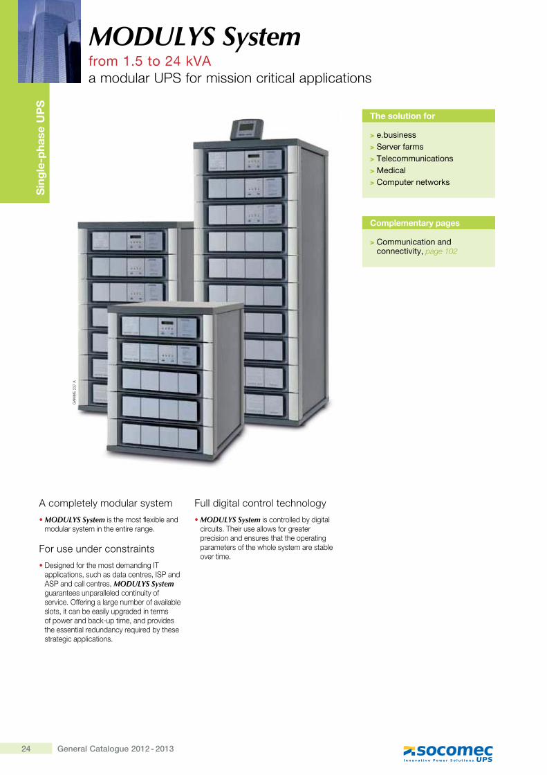
A completely modular system
� MODULYS System is the most flexible and modular system in the entire range.
For use under constraints
� Designed for the most demanding IT applications, such as data centres, ISP and ASP and call centres, MODULYS System guarantees unparalleled continuity of service. Offering a large number of available slots, it can be easily upgraded in terms of power and back-up time, and provides the essential redundancy required by these strategic applications.
Full digital control technology
� MODULYS System is controlled by digital circuits. Their use allows for greater precision and ensures that the operating parameters of the whole system are stable over time.
MODULYS Systemfrom 1.5 to 24 kVAa modular UPS for mission critical applications
Complementary pages
> Communication and connectivity, page 102
The solution for
>��\��������>����&������>�@���� �������� ��> Medical>�� ����������� �"�
GA
MM
E 2
37 A
25General Catalogue 2012 - 2013
MODULYS Systemfrom 1.5 to 24 kVA ���$��#�����<;�
<�$������ &�������
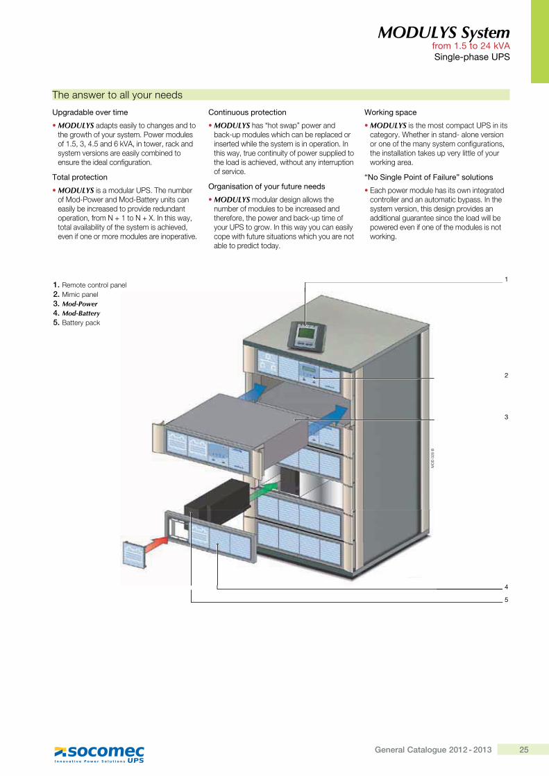
� MODULYS adapts easily to changes and to the growth of your system. Power modules of 1.5, 3, 4.5 and 6 kVA, in tower, rack and system versions are easily combined to ensure the ideal configuration.
Total protection
� MODULYS is a modular UPS. The number of Mod-Power and Mod-Battery units can easily be increased to provide redundant operation, from N + 1 to N + X. In this way, total availability of the system is achieved, even if one or more modules are inoperative.
� ����� ����� ����� �
� MODULYS has “hot swap” power and back-up modules which can be replaced or inserted while the system is in operation. In this way, true continuity of power supplied to the load is achieved, without any interruption of service.
��$����� �� �� ��������������
� MODULYS modular design allows the number of modules to be increased and therefore, the power and back-up time of your UPS to grow. In this way you can easily cope with future situations which you are not able to predict today.
= �"��$�����
� MODULYS is the most compact UPS in its category. Whether in stand- alone version or one of the many system configurations, the installation takes up very little of your working area.
]? ����$���; ���� �!�����^�� ���� ��
� Each power module has its own integrated controller and an automatic bypass. In the system version, this design provides an additional guarantee since the load will be powered even if one of the modules is not working.
The answer to all your needs
MO
D 0
28 B
1
2
4
5
3
1. Remote control panel2. Mimic panel3. Mod-Power4. Mod-Battery5. Battery pack
26 General Catalogue 2012 - 2013
MODULYS Systemfrom 1.5 to 24 kVA ���$��#�����<;�
Basic configurations
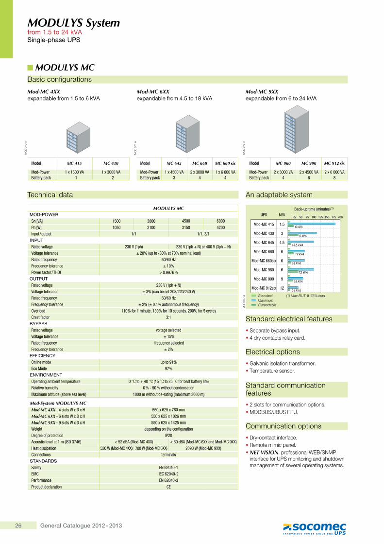
Mod-MC 4XX �'�������� ��_\`�� �j�"*J
Standard electrical features
� Separate bypass input.�'������� �� �����������
Electrical options
�Galvanic isolation transformer.� Temperature sensor.
Standard communication features
� 2 slots for communication options.� MODBUS/JBUS RTU.
Communication options
� Dry-contact interface.� Remote mimic panel.� NET VISION: professional WEB/SNMP
interface for UPS monitoring and shutdown management of several operating systems.
MODULYS
MODULYS
MO
D 0
70 A
Model MC 645 MC 660 MC 660 six
Mod-Power 1 x 4500 VA 2 x 3000 VA 1 x 6 000 VABattery pack 3 4 4
MODULYS
MODULYS
MO
D 0
71 A
Model MC 415 MC 430
Mod-Power 1 x 1500 VA 1 x 3000 VABattery pack 1 2
Model MC 960 MC 990 MC 912 six
Mod-Power 2 x 3000 VA 2 x 4500 VA 2 x 6 000 VABattery pack 4 6 8
MODULYS
MODULYS
MODULYS
MO
D 0
72 A
Mod-MC 6XX �'�������� ��x\`�� �_z�"*J
Mod-MC 9XX �'�������� ��j�� �{x�"*J
Technical data
MODULYS MC��Q#;�=�>Sn [VA] 1500 3000 4500 6000Pn [W] 1050 2100 3150 4200Input / output 1/1 1/1, 3/1
+?;<@Rated voltage 230 V (1ph) ����,�=�|�h;�'"���,�=�|�h;Voltage tolerance ± 20% (up to -30% at 70% nominal load)Rated frequency �������Frequency tolerance ± 10%$���'Z����'�<�>^ ���}�����
�<@;<@Rated voltage ����,�=�|h;Voltage tolerance ± 3% (can be set 208/220/240 V)Rated frequency ������Frequency tolerance ���,��}������������Z'������\;Overload 110% for 1 minute, 130% for 10 seconds, 200% for 5 cyclesCrest factor 3:1
�K;J��Rated voltage voltage selectedVoltage tolerance ± 15%Rated frequency frequency selectedFrequency tolerance ± 2%
�!!+�+�?�KOnline mode �=�����Eco Mode ��
�?*+>�?��?@Operating ambient temperature ��!`��|�"��!`,� �!`��� �!`Z�'���������'\��Z�;Relative humidity ��Q�������������&��������Maximum altitude (above sea level) �������������&�Q'����*,��[����������;
Mod-System MODULYS MCMod-MC 4XX Q"�����_[>[� 550 x 625 x 760 mmMod-MC 6XX Q������_[>[� 550 x 625 x 1026 mmMod-MC 9XX Q������_[>[� 550 x 625 x 1425 mmWeight depending on the configuration>�*'���Z='�������� IP20Acoustic level at 1 m (ISO 3746) �� ��&]�,��&Q�`"��; �����&]�,��&Q�`�����&��&Q�`���;����&����=����� ��_,��&Q�`"��; ��_,��&Q�`���; ����_,��&Q�`���;Connections terminals
�@J?QJ>Q�Safety {h���"�Q�EMC IEC 62040-2Performance {h���"�Q�Product declaration CE
MODULYS MC
An adaptable system
25 50 75 100 125 150 175 200UPS
Back-up time (minutes)(1)
Mod-MC 415 1.5
3
4.5
6
6
6
9
12
Mod-MC 430
Mod-MC 645
Mod-MC 660
Mod-MC 660six
Mod-MC 960
Mod-MC 990
Mod-MC 912six
Standard (1) Max BUT @ 75% loadMaximum Expandable
kVA
6 kVA
6 kVA
13.5 kVA
12 kVA
18 kVA
12 kVA
18 kVA
24 kVA
MO
D 0
77 A
27General Catalogue 2012 - 2013
MODULYS
MODULYS
MODULYS
MO
D 0
73 A
MODULYS Systemfrom 1.5 to 24 kVA ���$��#�����<;�
Range
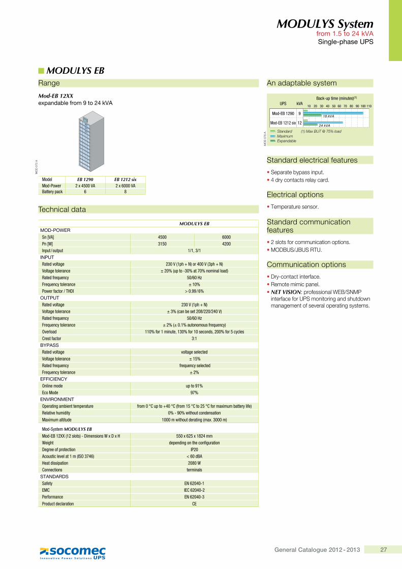
Mod-EB 12XX �'�������� ��|�� �{x�"*J
Standard electrical features
� Separate bypass input.�'������� �� �����������
Electrical options
� Temperature sensor.
Standard communication features
� 2 slots for communication options.� MODBUS/JBUS RTU.
Communication options
� Dry-contact interface.� Remote mimic panel.� NET VISION: professional WEB/SNMP
interface for UPS monitoring and shutdown management of several operating systems.
Model EB 1290 EB 1212 sixMod-Power ��[�" ����� ��[��������Battery pack 6 8
Technical data
MODULYS EB��Q#;�=�>Sn [VA] 4500 6000Pn [W] 3150 4200Input / output 1/1, 3/1
+?;<@Rated voltage ����,�=�|�h;�'"���,�=�|�h;Voltage tolerance ± 20% (up to -30% at 70% nominal load)Rated frequency �������Frequency tolerance ± 10%$���'Z����'�<�>^ ���}�����
�<@;<@Rated voltage ����,�=�|h;Voltage tolerance ± 3% (can be set 208/220/240 V)Rated frequency ������Frequency tolerance ���,��}������������Z'������\;Overload 110% for 1 minute, 130% for 10 seconds, 200% for 5 cyclesCrest factor 3:1
�K;J��Rated voltage voltage selectedVoltage tolerance ± 15%Rated frequency frequency selectedFrequency tolerance ± 2%
�!!+�+�?�KOnline mode �=�����Eco Mode ��
�?*+>�?��?@Operating ambient temperature Z'����!`�=��|"��!`,Z'��� �!`��� �!`Z�'��[���������'\��Z�;Relative humidity ��Q�������������&��������
Maximum altitude ������������&�'����*,��[}�����;
Mod-System MODULYS EB��&Q{]����,�������;Q>���������_[>[� 550 x 625 x 1824 mmWeight depending on the configuration>�*'���Z='�������� IP20Acoustic level at 1 m (ISO 3746) �����&]�����&����=����� 2080 WConnections terminals
�@J?QJ>Q�Safety {h���"�Q�EMC IEC 62040-2Performance {h���"�Q�
Product declaration CE
MODULYS EBAn adaptable system
10 20 30 40 50 60 70 80 90 100 110UPS
Back-up time (minutes)(1)
Mod-EB 1290 9
12Mod-EB 1212 six
Standard (1) Max BUT @ 75% loadMaximum Expandable
kVA
18 kVA
24 kVA
MO
D 0
76 A
28 General Catalogue 2012 - 2013
Sin
gle
-pha
se U
PS
A 19” rack solution”
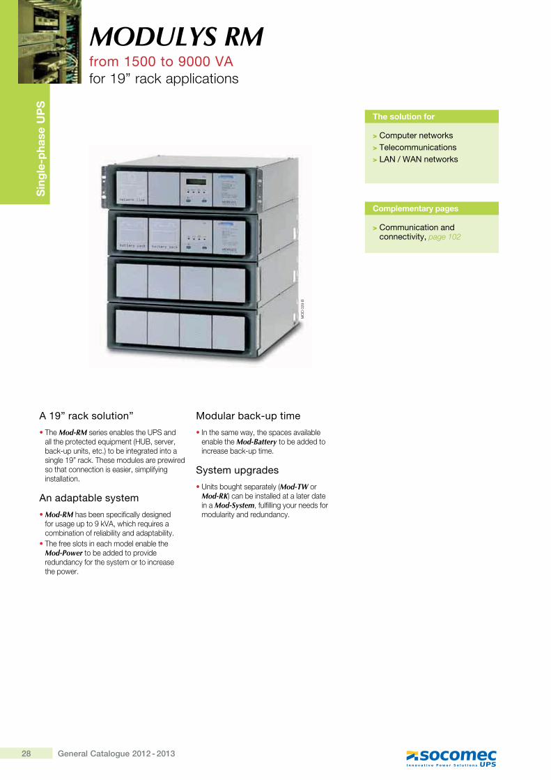
� The Mod-RM series enables the UPS and all the protected equipment (HUB, server, back-up units, etc.) to be integrated into a single 19” rack. These modules are prewired so that connection is easier, simplifying installation.
An adaptable system
� Mod-RM has been specifically designed for usage up to 9 kVA, which requires a combination of reliability and adaptability.
� The free slots in each model enable the Mod-Power to be added to provide redundancy for the system or to increase the power.
Modular back-up time
� In the same way, the spaces available enable the Mod-Battery to be added to increase back-up time.
System upgrades
� Units bought separately (Mod-TW or Mod-RK) can be installed at a later date in a Mod-System, fulfilling your needs for modularity and redundancy.
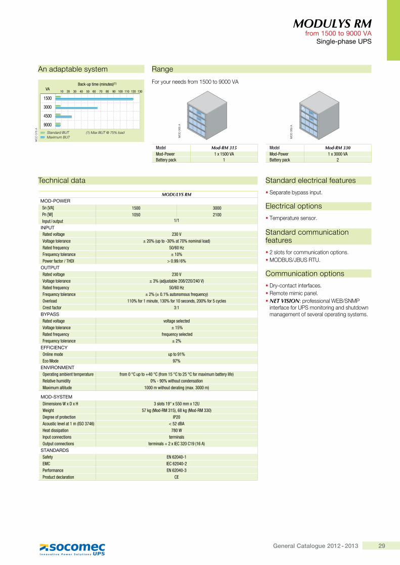
MODULYS RMfrom 1500 to 9000 VAfor 19” rack applications
Complementary pages
> Communication and connectivity, page 102
The solution for
>�� ����������� �"�> Telecommunications>�}J?�~�=J?����� �"�
MO
D 0
29 B
29General Catalogue 2012 - 2013
MODULYS RMfrom 1500 to 9000 VA
Single-phase UPS
Technical data
MODULYS RMMOD-POWERSn [VA] 1500 3000Pn [W] 1050 2100Input / output 1/1
INPUTRated voltage 230 V
Voltage tolerance ± 20% (up to -30% at 70% nominal load)Rated frequency �������Frequency tolerance ± 10%$���'Z����'�<�>^ ���}�����
OUTPUTRated voltage 230 VVoltage tolerance ± 3% (adjustable 208/220/240 V)Rated frequency ������Frequency tolerance ���,��}������������Z'������\;Overload 110% for 1 minute, 130% for 10 seconds, 200% for 5 cyclesCrest factor 3:1
BYPASSRated voltage voltage selectedVoltage tolerance ± 15%Rated frequency frequency selectedFrequency tolerance ± 2%
EFFICIENCYOnline mode �=�����Eco Mode ��
ENVIRONMENTOperating ambient temperature Z'����!`�=��|"��!`,Z'��� �!`��� �!`Z�'��[���������'\��Z�;Relative humidity ��Q�������������&����������[����������&� ������������&�'����*,��[}�����;
MOD-SYSTEM>���������_[>[� ���������[ ���[��#Weight 57 kg (Mod-RM 315), 68 kg (Mod-RM 330)>�*'���Z='�������� IP20Acoustic level at 1 m (ISO 3746) �� �&]�����&����=����� 780 WInput connections terminalsOutput connections ��'������|��[^{`���`��,���;
STANDARDSSafety EN 62040-1EMC IEC 62040-2Performance EN 62040-3Product declaration CE
Standard electrical features
� Separate bypass input.
Electrical options
� Temperature sensor.
Standard communication features
� 2 slots for communication options.� MODBUS/JBUS RTU.
Communication options
� Dry-contact interfaces.� Remote mimic panel.� NET VISION: professional WEB/SNMP
interface for UPS monitoring and shutdown management of several operating systems.
An adaptable system Range
For your needs from 1500 to 9000 VA
Model Mod-RM 315Mod-Power �[� ����]����'\=��� 1
MODULYS
MODULYS
MO
D 0
68 A
MODULYS
MODULYS
MO
D 0
69 A
Model Mod-RM 330Mod-Power �[������]����'\=��� 2
10 20 30 40 50 60 70 80 90 100 110 120 130VA
Back-up time (minutes)(1)
1500
3000
4500
9000
Standard BUT (1) Max BUT @ 75% loadMaximum BUT
MO
D 0
78 A
30 General Catalogue 2012 - 2013
Sin
gle
-pha
se U
PS
The solution for supplying power systems
� Thanks to its particular architecture, designed especially for the telecoms sector, the Mod-TC combines batteries with extended back-up time with high capacity.
� Mod-TC is the ideal solution for isolated, unmanned installations, such as radio stations or links, mobile radio stations for cellular phone networks and GSM - GPRS- UMTS repeaters.
Batteries and a charger adapted to prolonged back-up times
� Batteries have a lifespan of 10 years (AGMVRLA technology).
� Battery protection (fuses) connected by boards.
� Front battery access (easy maintenance).� To guarantee constant and reliable operation,
the 30 A battery charger provides rapid and � �������[������'��+�"##��[�� �����after each period of back-up.
Five models available with different architectures
� The Mod-TC 2XX stand-alone unit provides the ideal solution for applications which do not require an extended back-up time (more than 8 hours for the Mod-TC 230) and will not need to be upgraded.
� Mod-TC 3XX. The redundant modular system.
� Mod-TC 360 and Mod-TC 390. These are flexible, modular, redundant systems to which additional power modules may be installed to increase power or to obtain an operating redundancy N +1.
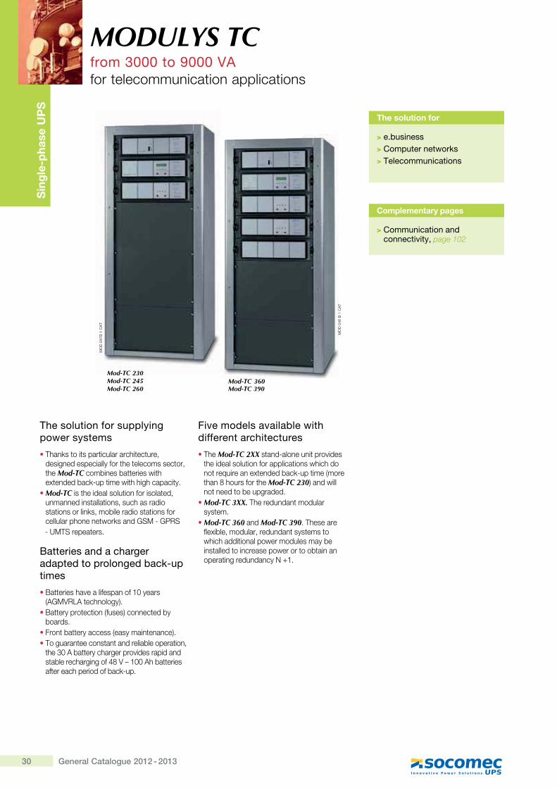
MODULYS TCfrom 3000 to 9000 VAfor telecommunication applications
Complementary pages
> Communication and connectivity, page 102
The solution for
> e.business> Computer networks> Telecommunications
MO
D 0
46 B
1 C
AT
MO
D 0
47B
1 C
AT
Mod-TC 230Mod-TC 245Mod-TC 260
Mod-TC 360Mod-TC 390
31General Catalogue 2012 - 2013
MODULYS TCfrom 3000 to 9000 VA
Single-phase UPS
Technical data
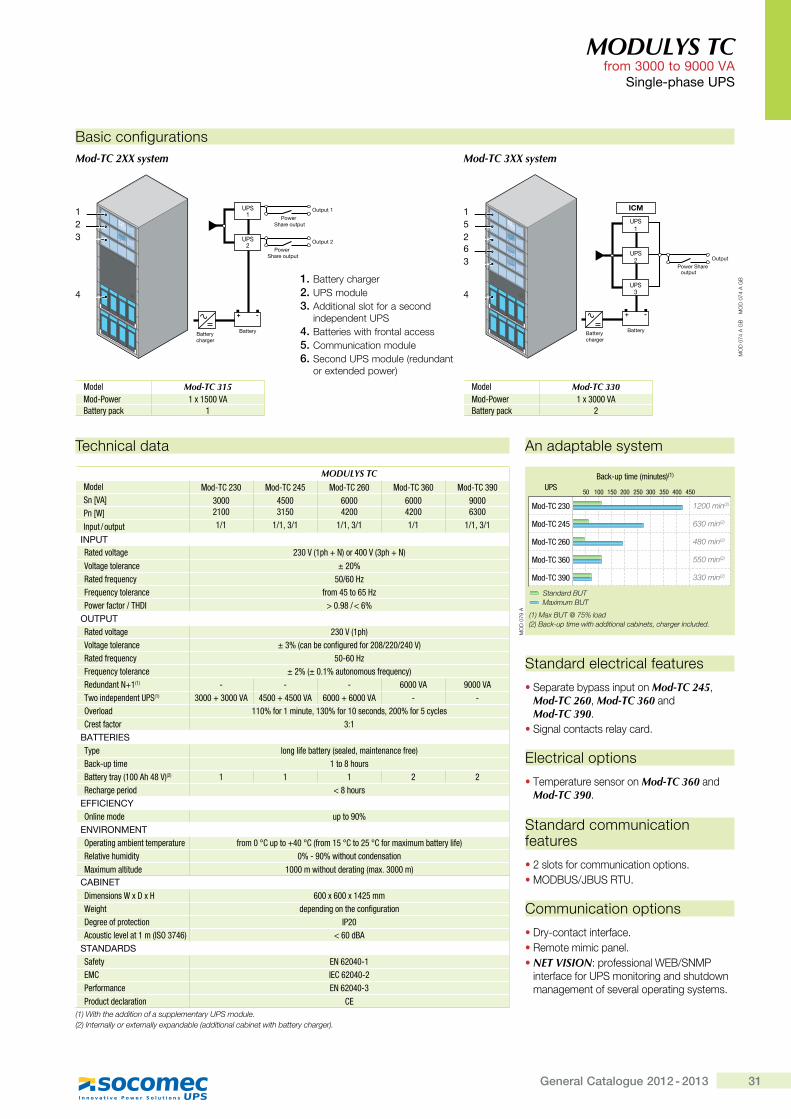
MODULYS TCModel Mod-TC 230 Mod-TC 245 Mod-TC 260 Mod-TC 360 Mod-TC 390Sn [VA] 3000 4500 6000 6000 9000Pn [W] 2100 3150 4200 4200 6300
Input / output 1/1 1/1, 3/1 1/1, 3/1 1/1 1/1, 3/1
INPUTRated voltage ����,�=�|h;�'"���,�=�|�h;
Voltage tolerance ± 20%Rated frequency �������Frequency tolerance Z'��" ��� ���$���'Z����'�<�>^ ���}�j����
OUTPUTRated voltage 230 V (1ph)Voltage tolerance ���,��������Z�*�'�&Z�'��j������"��;Rated frequency �Q����Frequency tolerance ���,��}������������Z'������\;Redundant N+1(1) - - - 6000 VA 9000 VATwo independent UPS(1) �����|������� " ���|�" ���� �����|������� - -Overload ����Z�'�������z����Z�'�������&�z����Z�' �\����`'���Z����' 3:1
BATTERIESType ���*��Z������'\,�����&z�����������Z'��;Back-up time ���j����'�]����'\�'�\,�����"j��;(2) 1 1 1 2 2Recharge period �j���'�
EFFICIENCYOnline mode up to 90%
ENVIRONMENTOperating ambient temperature Z'����!`�=��|"��!`,Z'��� �!`��� �!`Z�'��[���������'\��Z�;Relative humidity ��Q�������������&����������[����������&� ������������&�'����*,��[}�����;
CABINET>���������_[>[� ���[���[�"� ��Weight depending on the configuration>�*'���Z='�������� IP20����������:������,^%��"�; ����&]�
STANDARDSSafety EN 62040-1EMC IEC 62040-2Performance EN 62040-3Product declaration CE
(1) With the addition of a supplementary UPS module.(2) Internally or externally expandable (additional cabinet with battery charger).
Standard electrical features
� Separate bypass input on Mod-TC 245, Mod-TC 260, Mod-TC 360 and Mod-TC 390.
� Signal contacts relay card.
Electrical options
� Temperature sensor on Mod-TC 360 and Mod-TC 390.
Standard communication features
� 2 slots for communication options.� MODBUS/JBUS RTU.
Communication options
� Dry-contact interface.� Remote mimic panel.� NET VISION: professional WEB/SNMP
interface for UPS monitoring and shutdown management of several operating systems.
Basic configurationsMod-TC 2XX system
Model Mod-TC 315Mod-Power �[� ����Battery pack 1
UPS1
Battery
Power Share output
Power Share output
Output 1
Output 2
Battery charger
+ -
UPS2
MODULYS
MODULYS
MODULYS
MODULYS
MODULYS
MO
D 0
74 A
GB
Model Mod-TC 330Mod-Power �[������Battery pack 2
Mod-TC 3XX system
UPS1
ICM
UPS2
UPS3
Battery
Power Shareoutput
Output
Battery charger
� �
MODULYS
MODULYS
MODULYS
MODULYS
MODULYS
MODULYS
MO
D 0
74 A
GB
123
4
152
4
63
1. Battery charger2. UPS module3. Additional slot for a second
independent UPS4. Batteries with frontal access5. Communication module6. Second UPS module (redundant
or extended power)
An adaptable system
50 100 150 200 250 300 350 400 450UPS
Back-up time (minutes)(1)
Mod-TC 230
Mod-TC 245
Mod-TC 260
Mod-TC 360
Mod-TC 390
Standard BUT
(1) Max BUT @ 75% load(2) Back-up time with additional cabinets, charger included.
Maximum BUT
1200 min(2)
630 min(2)
480 min(2)
550 min(2)
330 min(2)
MO
D 0
79 A
32 General Catalogue 2012 - 2013
Sin
gle
-pha
se a
nd
thre
e-p
hase
UP
S
The ideal protection� Simple and reliable power protection.� Tailored for medium-sized businesses.� Advantages of advanced technology.
An excellent size/power/back-up time ratio� Ideal for sensitive professional applications.� Suitable for protection in IT environments
thanks to the internal back-up time and the possibility of installation in 19” rack cabinets.
Tailored to your environment� Easy to install.� Unique to the market with its highly compact
size.� Flexible back-up times: different back-up
time configurations are available either within the UPS standard cabinet or by using taller UPS cabinets, without changing the floor space (W = 444, D = 795 mm).
� Increased system availability placing two UPS in parallel.
� Combi Concept: BC108 and BC110 models are compatible with single or three-phase inputs, which can be configured during installation.
� Fitted with a multilanguage LCD display.� Separate rectifier supply and bypass
networks.
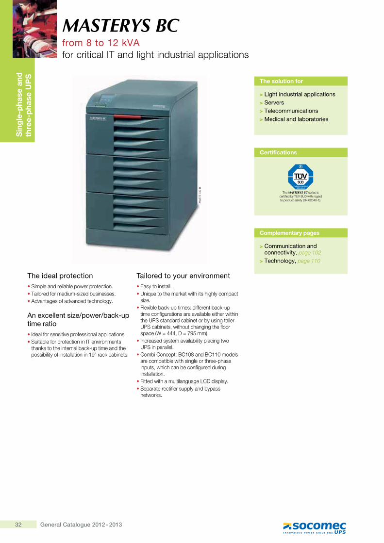
MASTERYS BCfrom 8 to 12 kVAfor critical IT and light industrial applications
The solution for
> Light industrial applications> Servers> Telecommunications> Medical and laboratories
Complementary pages
> Communication and connectivity, page 102
> Technology, page 110
MA
STE
049
B
Certifications
The MASTERYS BC series is ��� ������@�+~���� [����� ������� ���� �>�_�!*#'#X"K�
33General Catalogue 2012 - 2013
MASTERYS BC from 8 to 12 kVA
Single-phase and three-phase UPS
Technical data
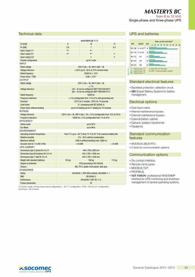
MASTERYS BC 8-12Sn [kVA] 8 10 12
Pn [kW] 5.6 7 8.4Input / output 1/1 �(1) �(1) -Input / output 3/1 �(1) �(1) �Input / output 3/3 - � �Parallel configuration up to 2 units
INPUTRated voltage ����,�=�|�h;z"���,�=�|�h;Voltage tolerance ± 20 % (up to -35 % at 70 % nominal load)Rated frequency �����������$���'Z����'�<�>^ �}�������(2)
OUTPUTRated voltage ����,�=�|h;z"���,�=�|h;
Voltage tolerance± 1 %
�=�|h��������Z�*�'�&��j(3)/220/230/240 V�=�|h��������Z�*�'�&���(3)/380/400/415 V
Rated frequency �������Frequency tolerance ���,���Z�*�'����Z'������j�����*���'����*���;Overload �� �Z�'��������z� ��Z�'�������&�Crest factor 3:1 (complying with IEC 62040-3)Power factor without derating up to 0.9 leading (up to 0.7 leading for 10 minutes)
BYPASSVoltage tolerance ����,�=�|h;z"���,�=�|h;�� �,���Z�*�'����Z'����������;Frequency tolerance ����������,���Z�*�'����Z'������j�;
EFFICIENCYOnline mode up to 92 %
Eco Mode up to 98 %ENVIRONMENT�=�'����*����������=�'���'� Z'����!`�=��|"��!`,Z'��� �!`��� �!`Z�'��[���������'\��Z�;Relative humidity 0 % - 95 % without condensation��[����������&� ������������&�'����*,��[}�����;Acoustic level at 1 m (ISO 3746) �� ��&]� �� ��&]�
UPS CABINET>����������\=�%,���'�;_[>[� """[� [j����>����������\=��,��&���;_[>[� """[� [������>����������\=�<,����;_[>[� """[� [�"����_��*����������&�'&�����'��� 155 kg 160 kg 175 kg>�*'���Z='�������� IP20 (according to IEC 60529)Colours @�?���z=������Z'���=������&�'�*'�\
STANDARDSSafety {h���"�Q�,<��%�>��'��Z��&;z{h��� �Q�Q�EMC {h���"�Q�Performance {h���"�Q����^Q%%Q����Product declaration CE
���������!����"�������#���$&#������&������'�"����������$��+����:�����'�"�������;�<= >�?�+F�'���G:�����'�"���������G��J������K�LN�F�������
Standard electrical features
� Backfeed protection: detection circuit.� EBS (Expert Battery System) for battery
management.
Electrical options
� Dual input mains.� Internal maintanance bypass.� External maintanance bypass.� External battery cabinet.� Galvanic isolation transformer.� Parallel kit.
Standard communication features
� MODBUS/JBUS RTU. �*��� ������������� ����� �����
Communication options
� Dry-contact interface.� Remote mimic panel.� MODBUS TCP.� PROFIBUS.� NET VISION: professional WEB/SNMP
interface for UPS monitoring and shutdown management of several operating systems.
UPS and batteries
10 20 30 40 50 60 70 80 90 100UPS IN/OUT kVA
Back-up time (minutes)(1)
(2)BC 108 1/1 or 3/1 8
1/1 or 3/1 10
3/1
3/3
3/3
12
10
12
BC 110
BC 112
BC 310
BC 312
Cabinet type “S” (1) Max BUT @ 70% load(2) With 1 external battery cabinet
Cabinet type “T”
Cabinet type “M”
}�
~@�
#!"
�
34 General Catalogue 2012 - 2013
Sin
gle
-pha
se a
nd
thre
e-p
hase
UP
S
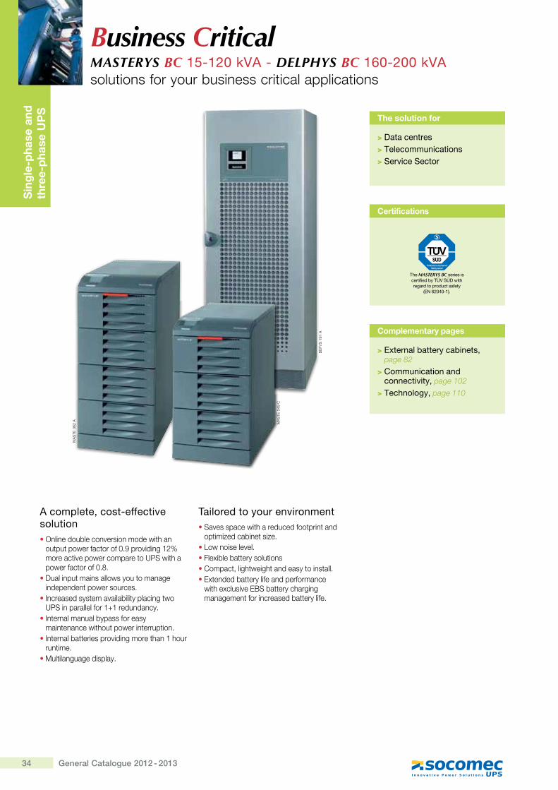
A complete, cost-effective solution� Online double conversion mode with an
output power factor of 0.9 providing 12% more active power compare to UPS with a power factor of 0.8.
� Dual input mains allows you to manage independent power sources.
� Increased system availability placing two UPS in parallel for 1+1 redundancy.
� Internal manual bypass for easy maintenance without power interruption.
� Internal batteries providing more than 1 hour runtime.
� Multilanguage display.
Tailored to your environment� Saves space with a reduced footprint and
optimized cabinet size.� Low noise level.� Flexible battery solutions� Compact, lightweight and easy to install.� Extended battery life and performance
with exclusive EBS battery charging management for increased battery life.
Business CriticalMASTERYS BC 15-120 kVA - DELPHYS BC 160-200 kVAsolutions for your business critical applications
The solution for
> Data centres> Telecommunications> Service Sector
Certifications
The MASTERYS BC series is certified by TÜV SÜD with regard to product safety
��?�j{�x�#_�\
Complementary pages
> External battery cabinets, page 82
> Communication and connectivity, page 102
> Technology, page 110
DE
FYS
191
A
MA
STE
062
A MA
STE
049
C
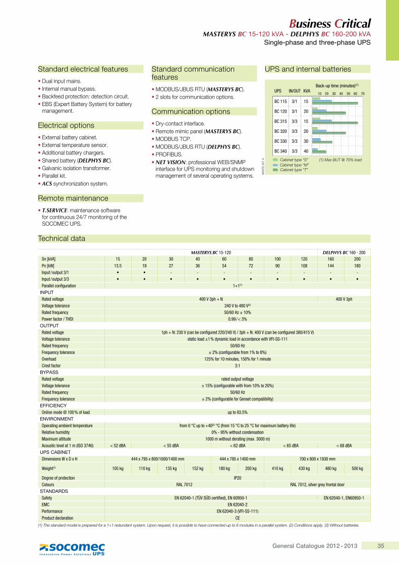
35General Catalogue 2012 - 2013
Business Critical MASTERYS BC 15-120 kVA - DELPHYS BC 160-200 kVA
Single-phase and three-phase UPS
Technical data
MASTERYS BC 15-120 DELPHYS BC 160 - 200Sn [kVA] 15 20 30 40 60 80 100 120 160 200
Pn [kW] 13.5 18 27 36 54 72 90 108 144 180Input / output 3/1 • • - - - - - - - -Input / output 3/3 • • • • • • • • • •Parallel configuration 1+1(1)
INPUTRated voltage 400 V 3ph + N 400 V 3phVoltage tolerance 240 V to 480 V(2)
Rated frequency 50/60�Hz ± 10%Power factor / THDI 0.99 / <�3%
OUTPUTRated voltage 1ph + N: 230 V (can be configured 220/240 V) / 3ph + N: 400 V (can be configured 380/415 V)Voltage tolerance static load ±1 % dynamic load in accordance with VFI-SS-111Rated frequency 50/60 HzFrequency tolerance ± 2% (configurable from 1% to 8%)Overload 125% for 10 minutes, 150% for 1 minuteCrest factor 3:1
BYPASSRated voltage rated output voltageVoltage tolerance ± 15% (configurable with from 10% to 20%)Rated frequency 50/60 HzFrequency tolerance ± 2% (configurable for Genset compatibility)
EFFICIENCYOnline mode @ 100 % of load up to 93.5%
ENVIRONMENTOperating ambient temperature from 0�°C up to +40(2)�°C (from 15�°C to 25�°C for maximum battery life)Relative humidity 0% - 95% without condensationMaximum altitude 1000 m without derating (max. 3000 m)Acoustic level at 1 m (ISO 3746) < 52 dBA < 55 dBA < 62 dBA < 65 dBA < 68 dBA
UPS CABINETDimensions W x D x H 444 x 795 x 800/1000/1400 mm 444 x 795 x 1400 mm 700 x 800 x 1930 mm
Weight(3) 105 kg 110 kg 135 kg 152 kg 180 kg 200 kg 410 kg 430 kg 480 kg 500 kg
Degree of protection IP20Colours RAL 7012 RAL 7012, silver grey frontal door
STANDARDSSafety EN 62040-1 (TÜV SÜD certified), EN 60950-1 EN 62040-1, EN60950-1EMC EN 62040-2Performance EN 62040-3 (VFI-SS-111)Product declaration CE
(1) The standard model is prepared for a 1+1 redundant system. Upon request, it is possible to have connected up to 6 modules in a parallel system. (2) Conditions apply. (3) Without batteries.
UPS and internal batteries
10 20 30 40 50 60 70UPS IN/OUT KVA
Back-up time (minutes)(1)
BC 115 3/1 15
3/1 20
3/3
3/3
3/3
3/3
15
20
30
40
BC 120
BC 315
BC 320
BC 330
BC 340
Cabinet type “S” (1) Max BUT @ 70% load
Cabinet type “T”
Cabinet type “M”
MA
STE
057
A
Standard electrical features
• Dual input mains.• Internal manual bypass.• Backfeed protection: detection circuit.• EBS (Expert Battery System) for battery
management.
Electrical options
• External battery cabinet.• External temperature sensor.• Additional battery chargers.• Shared battery (DELPHYS BC).• Galvanic isolation transformer.• Parallel kit.• ACS synchronization system.
Remote maintenance
• T.SERVICE: maintenance software for continuous 24/7 monitoring of the SOCOMEC UPS.
Standard communication features
• MODBUS/JBUS RTU (MASTERYS BC). • 2 slots for communication options.
Communication options
• Dry-contact interface.• Remote mimic panel (MASTERYS BC).• MODBUS TCP.• MODBUS/JBUS RTU (DELPHYS BC).• PROFIBUS.• NET VISION: professional WEB/SNMP
interface for UPS monitoring and shutdown management of several operating systems.
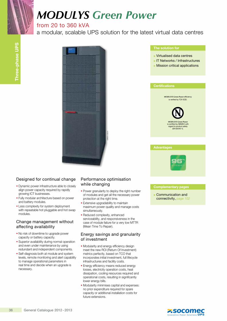
36 General Catalogue 2012 - 2013
Thr
ee-p
hase
UP
S
Designed for continual change
� Dynamic power infrastructure able to closely align power capacity required by rapidly growing ICT businesses.
� Fully modular architecture based on power and battery modules.
� Less complexity for system deployment with repeatable hot pluggable and hot swap modules.
Change management without affecting availability
� No risk of downtime to upgrade power capacity or battery capacity.
� Superior availability during normal operation and even under maintenance by using redundant and independent components.
� Self-diagnosis both at module and system levels, remote monitoring and alert capability to manage operational parameters in real time and decide when an upgrade is necessary.
Performance optimisation while changing
� Power granularity to deploy the right number of modules and get all the necessary power protection at the right time.
� Extensive upgradability to maintain maximum power quality and manage costs simultaneously.
� Reduced complexity, enhanced serviceability, and responsiveness in the case of module failure for a very low MTTR (Mean Time To Repair).
Energy savings and granularity of investment
� Modularity and energy efficiency design meet the new ROI (Return Of Investment) metrics perfectly, based on TCO that incorporates initial investment, full lifecycle infrastructures and facility costs.
� Energy efficiency means reduced energy losses, electricity operation costs, heat dissipation, cooling resources required and operational costs, resulting in significantly lower energy bills.
� Modularity minimises capital and expenses: no prior expenditure required for spare capacity or additional installation costs for future extensions.
MODULYS Green Powerfrom 20 to 360 kVAa modular, scalable UPS solution for the latest virtual data centres
Complementary pages
> Communication and connectivity, page 102
The solution for
>�*��������������������>�+@�?��� �"��~�+������������>������ ����������������� ��
GR
EE
N 0
39 A
Advantages
Certifications
MODULYS Green Power ����������������?����������
regard to product safety ��?�j{�x�#_�\
MODULYS Green Power efficiency
���&����������@�*���Q\
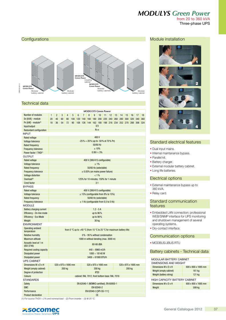
37General Catalogue 2012
MODULYS Green Powerfrom 20 to 360 kVA
@����#�����<;�
Technical data
MODULYS Green PowerNumber of modules 1 2 3 4 5 6 7 8 9 10 11 12 13 14 15 16 17 18Sn [kVA] - module 20 40 60 80 100 120 140 160 180 200 220 240 260 280 300 320 340 360Pn [kW] - module(3) 18 36 54 72 90 108 126 144 162 180 198 216 234 252 270 288 306 324Input/output 3/3
Redundant configuration N+x
+?;<@Rated voltage 400 V
Voltage tolerance -25 % + 20 % (up to -50 % at 70 % Pn)
Rated frequency 50/60 Hz
Frequency tolerance ± 10%
Power factor / THDI(1) 0.99 / < 3%
�<@;<@Rated voltage 400 V (380/415 configurable)
Voltage tolerance ± 1%Rated frequency �������,����������;Frequency tolerance ± 0.05% (on mains power failure)Voltage distortion ����Overload(2) 125% for 10 minutes, 150% for 1 minuteCrest factor 3:1
�K;J��Rated voltage 400 V (380/415 configurable)Voltage tolerance ��� �,���Z�*�'����Z'��j���� �;Rated frequency �������,����������;Frequency tolerance ������,���Z�*�'����Z'���z �� ���;
��Q<}�Battery charging current 1.2 - 5 AEfficiency - On-line mode up to 96 %Efficiency - Eco Mode up to 98 %Weight 30 kg
�?*+>�?��?@Operating ambient temperature Z'����!`�=��|"��!`,Z'��� �!`��� �!`Z�'��[���������'\��Z�;
Relative humidity 0 % - 95 % without condensationMaximum altitude 1000 m without derating (max. 3000 m)
Acoustic level at 1 m (ISO 3746) 60-66 dBA
Required cooling capacity 440 ÷ 8960 m3/hDissipated power 1000 ÷ 18140 WDissipated power 3400 ÷ 61900 BTU/h
<;���J�+?�@Dimensions W x D x H 520 x 975 x 1695 mm 520 x 975 x 1695 mm 520 x 975 x 1695 mmWeight (empty cabinet) 200 kg 200 kg 200 kgDegree of protection IP20Colours cabinet: RAL 7012, front bottom base: RAL 7016
�@J?QJ>Q�Safety EN 62040-1 (NEMKO certified), EN 60950-1EMC EN 62040-2Performance EN 62040-3 [VFI-SS-111]Product declaration CE
����Q����������<= X�?�+�F���Y������������Y��$��+��Q��������������$��G��J�+�Z��
Standard electrical features
� Dual input mains.� Internal maintanance bypass.� Parallel kit.� Battery charger.� External modular battery cabinet.� Long life batteries.
Electrical options
� External maintanance bypass up toZ!#�Q+��
�Relay card.
Standard communication features
� Embedded LAN connection: professional WEB/SNMP interface for UPS monitoring and shutdown management of several operating systems.
� Dry-contact interface.
Communication options
� MODBUS/JBUS RTU
Configurations
MODULYS Green Power
MODULYS Green Power
MODULYS Green Power
Modularbattery cabinet
Modularbattery cabinet
Modularbattery cabinetsModular
battery cabinet
Couplingcabinet
MODULYSGreen Power
MODULYSGreen Power
MODULYSGreen Power
GR
EE
N 0
91 A
Module installation
1
3
2
4
Battery cabinets - Technical data
��Q<}J>��J@@�>K��J�+?�@Q+��?�+�?��J?Q�=�+XY@Dimensions W x D x H 600 x 900 x 1695 mmWeight (empty cabinet) 161 kgWeight (battery string) 121 kg
Y+XY��J;J�+@K��J@@�>K��J�+?�@Dimensions W x D x H 600 x 900 x 1695 mmWeight 599 kg
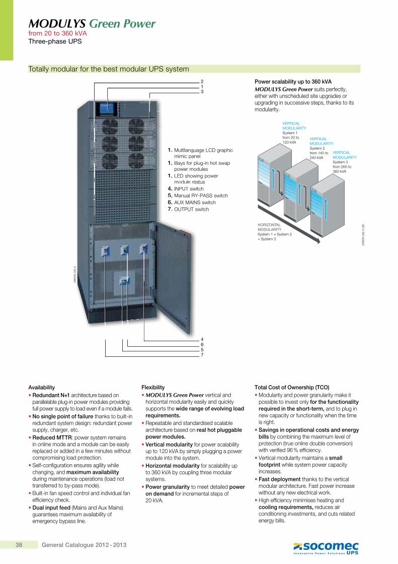
38 General Catalogue 2012 - 2013
MODULYS Green Powerfrom 20 to 360 kVA @����#�����<;�
Totally modular for the best modular UPS system
Power scalability up to 360 kVAMODULYS Green Power suits perfectly, either with unscheduled site upgrades or upgrading in successive steps, thanks to its modularity.
1. Multilanguage LCD graphic mimic panel
1. Bays for plug-in hot swap power modules
1. LED showing power module status
4. INPUT switch5. Manual BY-PASS switch6. AUX MAINS switch7. OUTPUT switch
Availability� Redundant N+1 architecture based on
parallelable plug-in power modules providing full power supply to load even if a module fails.
� No single point of failure thanks to built-in redundant system design: redundant power ��������[������� ��
� Reduced MTTR: power system remains in online mode and a module can be easily replaced or added in a few minutes without compromising load protection.
� Self-configuration ensures agility while changing, and maximum availability during maintenance operations (load not transferred to by-pass mode).
� Built-in fan speed control and individual fan efficiency check.
� Dual input feed (Mains and Aux Mains) guarantees maximum availability of emergency bypass line.
Flexibility � MODULYS Green Power vertical and
horizontal modularity easily and quickly supports the wide range of evolving load requirements.
� Repeatable and standardised scalable architecture based on real hot pluggable power modules.
� Vertical modularity for power scalability �� �"*#Q+��������������������module into the system.
� Horizontal modularity for scalability up �Z!#Q+���������� [����������systems.
� Power granularity to meet detailed power on demand for incremental steps of *#�Q+��
Total Cost of Ownership (TCO) � Modularity and power granularity make it
possible to invest only for the functionality required in the short-term, and to plug in new capacity or functionality when the time is right.
� Savings in operational costs and energy bills by combining the maximum level of protection (true online double conversion) with verified 96 % efficiency.
�+�� ������������ ����� �����small footprint while system power capacity increases.
� Fast deployment thanks to the vertical modular architecture. Fast power increase without any new electrical work.
� High efficiency minimises heating and cooling requirements, reduces air conditioning investments, and cuts related energy bills.
MODULYS Green Power
MODULYS Green Power
MODULYS Green Power
VERTICALMODULARITYSystem 1from 20 to120 kVA
VERTICALMODULARITYSystem 2from 140 to 240 kVA
HORIZONTALMODULARITYSystem 1 + System 2 + System 3
VERTICALMODULARITYSystem 3from 260 to 360 kVA
GR
EE
N 0
92 A
GB
1. Multilanguamimic pan
1. Bays for plpower mod
1. LED showimodule sta
4. INPUT swi5. Manual BY6. AUX MAIN7. OUTPUT s
GR
EE
N 0
35 A
_3
2
x657
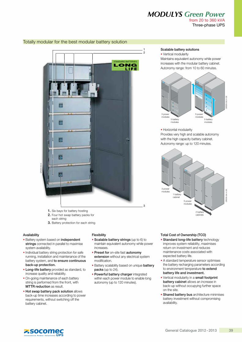
39General Catalogue 2012 - 2013
MODULYS Green Powerfrom 20 to 360 kVA
@����#�����<;�
MODULYS Green Power
3 powermodules
1 batterycabinet
2 batterycabinets
5 powermodules
MODULYS Green Power
GR
EE
N 0
94 A
GB
Totally modular for the best modular battery solution
Scalable battery solutions�+�� ������������ �Maintains equivalent autonomy while powerincreases with the modular battery cabinet.Autonomy range: from 10 to 60 minutes.
� Horizontal modularityProvides very high and scalable autonomywith the high capacity battery cabinet.Autonomy range: up to 120 minutes.
MODULYS Green Power
MODULYS Green Power
3 powermodules
5 powermodules
3 batterymodules
5 batterymodules
GR
EE
N 0
93 A
GB
Availability� Battery system based on independent
strings connected in parallel to maximise system availability.
� Individual battery string protection for safe running, installation and maintenance of the battery system, and to ensure continuous back-up protection.
� Long-life battery provided as standard, to increase quality and reliability.
� On-going maintenance of each battery string is performed from the front, with MTTR reduction as result.
� Hot swap battery pack solution allows back-up time increases according to power requirements, without switching off the battery cabinet.
Flexibility � Scalable battery strings (up to 6) to
maintain equivalent autonomy while power increases.
� Preset for on-site fast autonomy extension without any electrical system modification.
� Battery scalability based on unique battery packs (up to 24).
� Powerful battery charger integrated within each power module to enable long autonomy (up to 120 minutes).
Total Cost of Ownership (TCO) � Standard long-life battery technology
improves system reliability, maximises return on investment and reduces maintenance costs associated with expected battery life.
� A standard temperature sensor optimises the battery recharging parameters according to environment temperature to extend battery life and investment.
�+�� ������������ ����small footprint battery cabinet allows an increase in back-up without occupying further space on the site.
� Shared battery bus architecture minimises battery investment without compromising availability.
1. Six bays for battery hosting2. Four hot swap battery packs for
each string3. Battery protection for each string
GR
EE
N 0
54 A
STANDARD BATTERIES
LONGL I F E
_
3
STST AANDARD BATT TTERIETTAAA S
GLONGEFL IL I F EL I
2
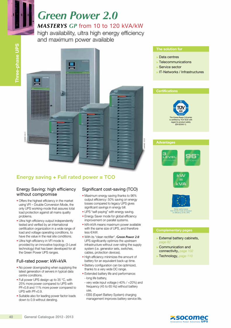
40 General Catalogue 2012 - 2013
Thr
ee-p
hase
UP
S
Energy Saving: high efficiency without compromise������� [�[�[�� ������������ [����Q�
����+�?�������]��^������}���� [�������~���Q��X���� [� ������� � ��������� �� �������� ������������� ����������
��� ��[�[������������ �� ���������� �� �� �����^������������� ���� �������� ����� ���������� �����������������������^�� ������� ������� ����� �[�^� [�^������ [������� ������ �����
��� ��[�[������������+�?���������^������������^� �^� ������>ZX{�^�� ��[�����K [� [��������^������������ [�������������~������
Full-rated power: kW=kVA�_����������������[���������� [�
�� �� ����� ��������^����� �������� ���� ������� �����
������������~������� �Z\�]��� [*\������������������ ���~�� [���#�����""������������������ ���~�� [���#���
�~�� ������������������������� ����������� �#���� [�� ���� ���
Significant cost-saving (TCO)�}�������������^�� [��Q� ��!�
�� �� �����������\#���^����������������������� ��������~�^����������� ��^���������������
���~�����X�������� [�������^���������~�^������������������������
�����^���� ������������� �����Q`�Q+�������������������^�������
�� [ [�������������~���� [������������$Q`�
� � [� ���������� �������Green Power 2.0��~��������� ���� ����� [���� ���������� ��� ����� [�� �^���� �� [���������� ��>��������� ���� ����� �[������������� �� �����^����K�
���[������������������� [������ ���� ������������^���� ���QX�� ����
�|� ����������� ���������� ������� [��Q� ��^��������]�����
��� ������� ����������������������X��������� ����X ����������� ^�� ��>X'#�$�*#�K���
���������>'\ �!\��K�� [�� �� �������
X�|~>����� |� ���~�� ��K�[������������ �����^���� ������^��������
Green Power 2.0MASTERYS GP from 10 to 120 kVA/kW[�[�^�������� ���� ��[�[�������������������������������^�������
The solution for
> Data centres> Telecommunications> Service sector> IT-Networks / Infrastructures
Complementary pages
> External battery cabinets, page 82
> Communication and connectivity, page 102
> Technology, page 110
��
}}
�*
#*]
Certifications
The Green Power 2.0 series is certified by TÜV SÜD with
regard to product safety ��?�j{�x�#_�\
��
}}
�"
*\|
Energy saving + Full rated power = TCO
Advantages
Better performancethan the EU Code of Conduct
on efficiency of AC UPS
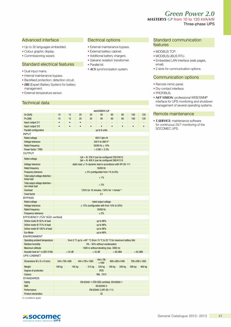
41General Catalogue 2012 - 2013
Green Power 2.0MASTERYS GP from 10 to 120 kVA/kW
Three-phase UPS
Technical data
MASTERYS GPSn [kVA] 10 15 20 30 40 60 80 100 120
Pn [kW] 10 15 20 30 40 60 80 100 120Input / output 3/1 • • • - - - - - -Input / output 3/3 • • • • • • • • •Parallel configuration up to 6 units
INPUTRated voltage 400 V 3ph+NVoltage tolerance 240 V to 480 V(1)
Rated frequency 50/60�Hz ± 10%Power factor / THDI >�0.99 / <�2.5%
OUTPUT
Rated voltage 1ph + N: 230 V (can be configured 220/240 V)3ph + N: 400 V (can be configured 380/415 V)
Voltage tolerance static load ±1 % dynamic load in accordance with VFI-SS-111Rated frequency 50/60 HzFrequency tolerance ± 2% (configurable from 1% to 8%)
Total output voltage distortion - linear load < 1%
Total output voltage distortion - non-linear load < 3%
Overload 125% for 10 minutes, 150% for 1 minute (1)
Crest factor 3:1BYPASSRated voltage rated output voltageVoltage tolerance ± 15% (configurable with from 10% to 20%)Rated frequency 50/60 HzFrequency tolerance ± 2%
EFFICIENCY (TÜV SÜD verified)Online mode @ 50 % of load up to 96%Online mode @ 75 % of load up to 96%Online mode @ 100 % of load up to 96%Eco Mode up to 98%
ENVIRONMENTOperating ambient temperature from 0�°C up to +40(1)�°C (from 15�°C to 25�°C for maximum battery life)Relative humidity 0% - 95% without condensationMaximum altitude 1000 m without derating (max. 3000 m)Acoustic level at 1 m (ISO 3746) < 52 dB < 55 dB < 60 dBA < 65 dBA
UPS CABINET
Dimensions W x D x H (mm) 444 x 795 x 800 444 x 795 x 1000 444 x 795 x 1400 600 x 800 x1400 700 x 800 x 1930
Weight 190 kg 195 kg 315 kg 320 kg 180 kg 200 kg 380 kg 460 kgDegree of protection IP20Colours RAL 7012
STANDARDSSafety EN 62040-1 (TÜV SÜD certified), EN 60950-1EMC EN 62040-2Performance EN 62040-3 (VFI-SS-111)Product declaration CE
(1) conditions apply
Advanced interface
• Up to 30 languages embedded.• Colour graphic display.• Commissioning wizard.
Standard electrical features
• Dual input mains.• Internal maintanance bypass.• Backfeed protection: detection circuit.• EBS (Expert Battery System) for battery
management.• External temperature sensor.
Electrical options
• External maintanance bypass.• External battery cabinet.• Additional battery chargers.• Galvanic isolation transformer.• Parallel kit.• ACS synchronization system.
Standard communication features
• MODBUS TCP.• MODBUS/JBUS RTU. • Embedded LAN interface (web pages,
email).• 2 slots for communication options.
Communication options
• Remote mimic panel.• Dry-contact interface.• PROFIBUS.• NET VISION: professional WEB/SNMP
interface for UPS monitoring and shutdown management of several operating systems.
Remote maintenance
• T.SERVICE: maintenance software for continuous 24/7 monitoring of the SOCOMEC UPS.
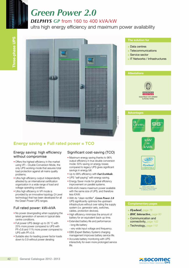
42 General Catalogue 2012 - 2013
Green Power 2.0DELPHYS GP from 160 to 400 kVA/kWultra high energy efficiency and maximum power availability
Thre
e-ph
ase
UP
S
The solution for
> Data centres> Telecommunications> Service sector> IT Networks / Infrastructures
Complementary pages
> Flywheel, page 78
> BHC Interactive, page 80
> Communication and connectivity, page 102
> Technology, page 110
GA
MM
E 1
84 B
Energy saving: high efficiency without compromise�Offers the highest efficiency in the market
using VFI – Double Conversion Mode, the only UPS working-mode that assures total load protection against all mains quality problems.
�Ultra high efficiency output independently attested by an international certification organization in a wide range of load and voltage operating condition.
�Ultra high efficiency in VFI mode is provided by an innovative topology (3-Level technology) that has been developed for all the Green Power UPS ranges.
Full rated power: kW=kVA�No power downgrading when supplying the
latest generation of servers in typical data centre conditions.
�Full power UPS design up to 35 °C with 25% more power compared to UPS with PF=0.8 and 11% more power compared to UPS with PF=0.9.
�Suitable also for leading power factor loads down to 0.9 without power derating
Significant cost-saving (TCO)�Maximum energy saving thanks to 96%
output efficiency in true double conversion mode: 50% saving on energy losses compared to legacy UPS gives significant savings in energy bill.
�Up to 99% efficiency with Fast EcoMode.�UPS “self-paying” with energy saving.�Energy Saver mode for global efficiency
improvement on parallel systems.�kW=kVA means maximum power available
with the same size of UPS, and therefore less €/kW.
�With its “clean rectifier”, Green Power 2.0 UPS significantly optimize the upstream infrastructure without over rating the supply ��� ��>���������� ���� ����� �[���cables, protection devices).
�High efficiency minimizes the amount of battery for an equivalent back-up time.
�Extended battery life and performance:- long life battery- very wide input voltage and frequency.
�EBS (Expert Battery System) charging management improves battery service life.
�Accurate battery monitoring with UPS interactivity for even more prolonged service life.
Attestations
B U R E A UV E R I T A S
Green Power 2.0 is attested by Bureau Veritas
Energy saving + Full rated power = TCO
Advantages
Better performancethan the EU Code of Conduct
on efficiency of AC UPS
FlywheelCOMPATIBLE
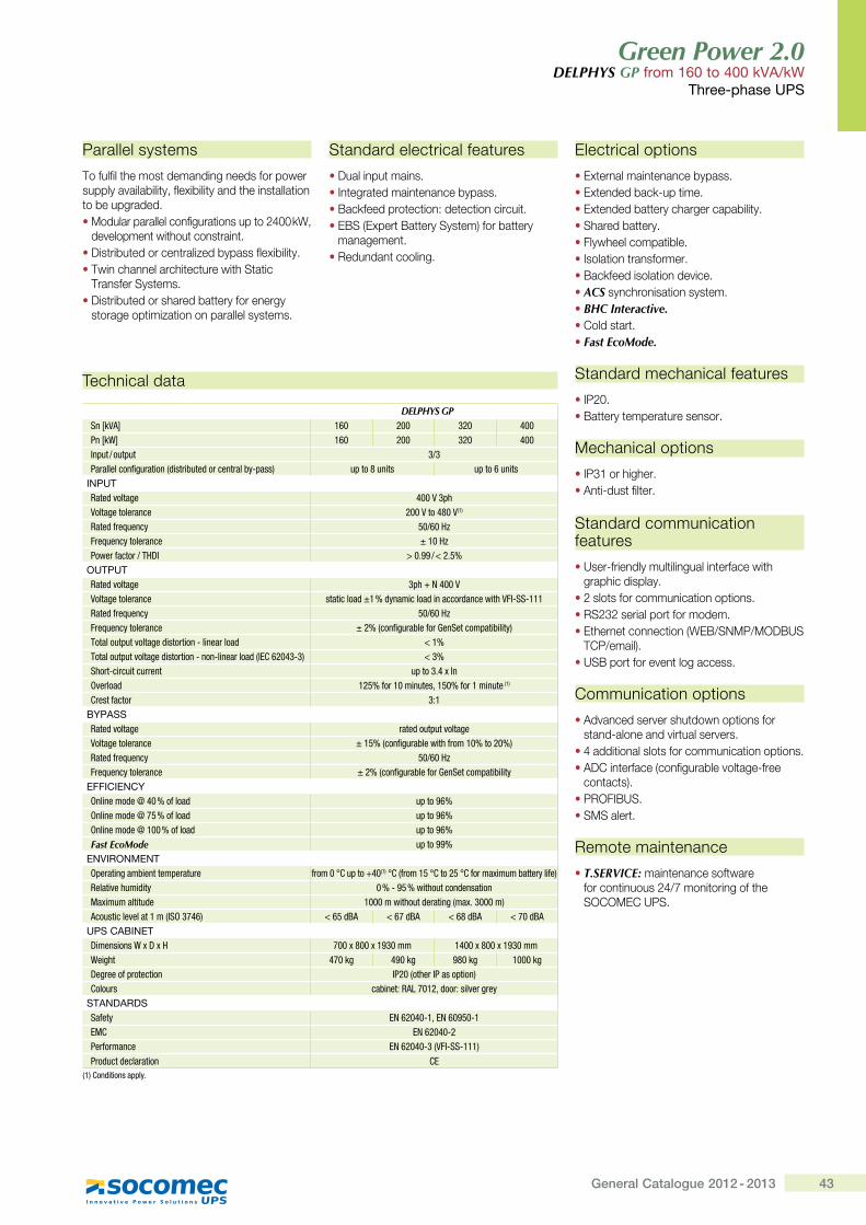
43General Catalogue 2012 - 2013
Green Power 2.0 DELPHYS GP from 160 to 400 kVA/kW
Three-phase UPS
Parallel systems
To fulfil the most demanding needs for power supply availability, flexibility and the installation to be upgraded.• Modular parallel configurations up to 2400 kW,
development without constraint.• Distributed or centralized bypass flexibility.• Twin channel architecture with Static
Transfer Systems.• Distributed or shared battery for energy
storage optimization on parallel systems.
Standard electrical features
• Dual input mains.• Integrated maintenance bypass.• Backfeed protection: detection circuit.• EBS (Expert Battery System) for battery
management.• Redundant cooling.
Technical data
DELPHYS GPSn [kVA] 160 200 320 400Pn [kW] 160 200 320 400Input / output 3/3Parallel configuration (distributed or central by-pass) up to 8 units up to 6 units
INPUTRated voltage 400 V 3phVoltage tolerance 200 V to 480 V(1)
Rated frequency 50/60 HzFrequency tolerance ± 10 HzPower factor / THDI > 0.99 / < 2.5%
OUTPUTRated voltage 3ph + N 400 VVoltage tolerance static load ±1 % dynamic load in accordance with VFI-SS-111Rated frequency 50/60 HzFrequency tolerance ± 2% (configurable for GenSet compatibility)Total output voltage distortion - linear load <�1%Total output voltage distortion - non-linear load (lEC 62043-3) <�3%Short-circuit current up to 3.4 x InOverload 125% for 10 minutes, 150% for 1 minute (1)
Crest factor 3:1BYPASSRated voltage rated output voltageVoltage tolerance ± 15% (configurable with from 10% to 20%)Rated frequency 50/60 HzFrequency tolerance ± 2% (configurable for GenSet compatibility
EFFICIENCYOnline mode @ 40 % of load up to 96%Online mode @ 75 % of load up to 96%Online mode @ 100 % of load up to 96%Fast EcoMode up to 99%
ENVIRONMENTOperating ambient temperature from 0�°C up to +40(1)�°C (from 15�°C to 25�°C for maximum battery life)Relative humidity 0 % - 95 % without condensationMaximum altitude 1000 m without derating (max. 3000 m)Acoustic level at 1 m (ISO 3746) < 65 dBA < 67 dBA < 68 dBA < 70 dBA
UPS CABINETDimensions W x D x H 700 x 800 x 1930 mm 1400 x 800 x 1930 mmWeight 470 kg 490 kg 980 kg 1000 kgDegree of protection IP20 (other IP as option)Colours cabinet: RAL 7012, door: silver grey
STANDARDSSafety EN 62040-1, EN 60950-1EMC EN 62040-2Performance EN 62040-3 (VFI-SS-111)Product declaration CE
(1) Conditions apply.
Electrical options
• External maintenance bypass.• Extended back-up time.• Extended battery charger capability.• Shared battery.• Flywheel compatible.• Isolation transformer.• Backfeed isolation device.• ACS synchronisation system.• BHC Interactive.• Cold start.• Fast EcoMode.
Standard mechanical features
• IP20.• Battery temperature sensor.
Mechanical options
• IP31 or higher.• Anti-dust filter.
Standard communication features
• User-friendly multilingual interface with graphic display.
• 2 slots for communication options.• RS232 serial port for modem.• Ethernet connection (WEB/SNMP/MODBUS
TCP/email).• USB port for event log access.
Communication options
• Advanced server shutdown options for stand-alone and virtual servers.
• 4 additional slots for communication options.• ADC interface (configurable voltage-free
contacts).• PROFIBUS.• SMS alert.
Remote maintenance
• T.SERVICE: maintenance software for continuous 24/7 monitoring of the SOCOMEC UPS.
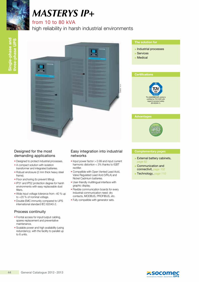
44 General Catalogue 2012 - 2013
Sin
gle
-pha
se a
nd
thre
e-p
hase
UP
S
Designed for the most demanding applications� Designed to protect industrial processes.� A compact solution with isolation
transformer and integrated batteries.� Robust enclosure (2 mm thick heavy steel
frame).� Floor anchoring (to prevent tilting).� IP31 and IP52 protection degree for harsh
environments with easy replaceable dust filters.
� Wide input voltage tolerance from -40 % up to +20 % of nominal voltage.
� Double EMC immunity compared to UPS international standard IEC 62040-2.
Process continuity� Frontal access for input/output cabling,
spares replacement and preventative maintenance.
� Scalable power and high availability (using redundancy), with the facility to parallel up to 6 units.
Easy integration into industrial networks � Input power factor > 0.99 and input current
harmonic distortion < 3% thanks to IGBT rectifier.
� Compatible with Open Vented Lead Acid, Valve Regulated Lead Acid (VRLA) and Nickel Cadmium batteries.
� User-friendly multilingual interface with graphic display.
� Flexible communication boards for every industrial communication need: dry contacts, MODBUS, PROFIBUS, etc.
� Fully compatible with generator sets.
MASTERYS IP+from 10 to 80 kVAhigh reliability in harsh industrial environments
The solution for
> Industrial processes> Services> Medical
Complementary pages
> External battery cabinets, page 82
> Communication and connectivit, page 102
> Technology, page 110
Advantages
Available
IP52models
GA
MM
E 1
40 A
Certifications
The MASTERYS IP+ series is certified by TÜV SÜD with regard to product safety
��?�j{�x�#_�\
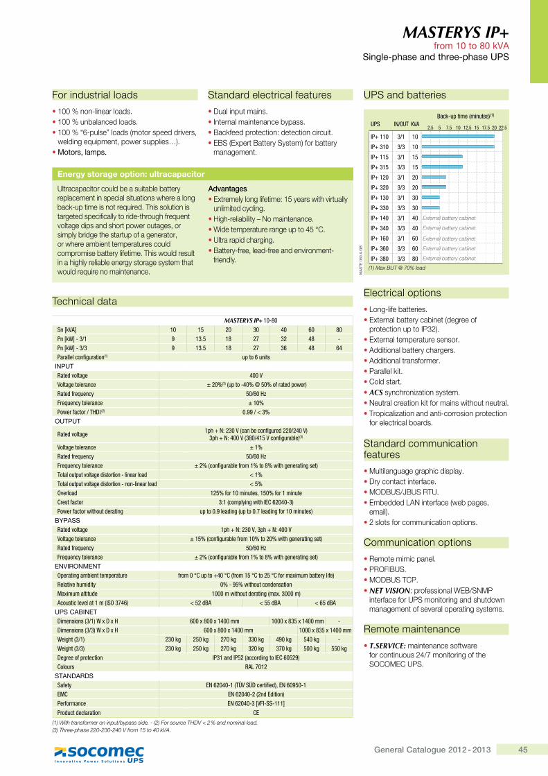
45General Catalogue 2012 - 2013
MASTERYS IP+ from 10 to 80 kVA
���$��#�������������#�����<;�
Technical data
MASTERYS IP+ 10-80Sn [kVA] 10 15 20 30 40 60 80Pn [kW] - 3/1 9 13.5 18 27 32 48 -Pn [kW] - 3/3 9 13.5 18 27 36 48 64Parallel configuration(1) up to 6 units
+?;<@Rated voltage "����Voltage tolerance ± 20%(3) (up to -40% @ 50% of rated power)Rated frequency �������Frequency tolerance ± 10%$���'Z����'�<�>^ (2) 0.99 / < 3%
�<@;<@
Rated voltage �=�|�h������,��������Z�*�'�&�����"��;�=�|�h�"���,�j��"� ����Z�*�'����;(3)
Voltage tolerance ± 1%Rated frequency �������Frequency tolerance ���,���Z�*�'����Z'������j�����*���'����*���;Total output voltage distortion - linear load < 1%Total output voltage distortion - non-linear load < 5%Overload �� �Z�'���������z� ��Z�'�������Crest factor ���,���=�\��*����^{`���"�Q�;Power factor without derating �=���}����&��*,�=���}���&��*Z�'����������;
BYPASSRated voltage �=�|�h������z�=�|�h�"���Voltage tolerance �� �,���Z�*�'����Z'��������������*���'����*���;Rated frequency �������Frequency tolerance ���,���Z�*�'����Z'������j�����*���'����*���;
ENVIRONMENT�=�'����*����������=�'���'� Z'����!`�=��|"��!`,Z'��� �!`��� �!`Z�'��[���������'\��Z�;@�����:�����&��\ 0% - 95% without condensation��[����������&� ������������&�'����*,��[}�����;����������:������,^%��"�; < 52 dBA < 55 dBA < 65 dBA
<;���J�+?�@>���������,���;_[>[� ���[j��[�"���� ����[j� [�"���� ->���������,���;_[>[� ���[j��[�"���� ����[j� [�"����Weight (3/1) 230 kg 250 kg 270 kg 330 kg 490 kg 540 kg -Weight (3/3) 230 kg 250 kg 270 kg 320 kg 370 kg 500 kg 550 kg>�*'���Z='�������� ^$����&^$ �,����'&��*��^{`�� ��;Colours RAL 7012
STANDARDSSafety {h���"�Q�,<��%�>��'��Z��&;z{h��� �Q�{�` {h���"�Q�,��&{&�����;$�'Z�'����� {h���"�Q����^Q%%Q����Product declaration `{
����[��#������'�����������&��:��&������Y���$��+��Q����������<= X�?�+�F���Y������������Y�� (3) Three-phase 220-230-240 V from 15 to 40 kVA.
For industrial loads
� 100 % non-linear loads.� 100 % unbalanced loads.� 100 % “6-pulse” loads (motor speed drivers,
welding equipment, power supplies…).� � � ��������\
UPS and batteries
2.5 5 7.5 10 12.5 15 17.5 20 22.5UPS IN/OUT KVA
Back-up time (minutes)(1)
IP+ 110
IP+ 310
IP+ 115
IP+ 315
IP+ 120
IP+ 320
IP+ 130
IP+ 330
IP+ 140
IP+ 340
IP+ 160
IP+ 360
IP+ 380
3/1
3/3
3/1
3/3
3/1
3/3
3/1
3/3
3/1
3/3
3/1
3/3
3/3
10
10
15
15
20
20
30
30
40
40
60
60
80(1) Max BUT @ 70% load
External battery cabinet
External battery cabinet
External battery cabinet
External battery cabinet
External battery cabinet
MA
STE
060
A G
B
Standard electrical features
� Dual input mains.� Internal maintenance bypass.� Backfeed protection: detection circuit.� EBS (Expert Battery System) for battery
management.
Electrical options
�Long-life batteries.� External battery cabinet (degree of
protection up to IP32).� External temperature sensor.� Additional battery chargers.� Additional transformer.� Parallel kit.� Cold start.� ACS synchronization system.� Neutral creation kit for mains without neutral.� Tropicalization and anti-corrosion protection
for electrical boards.
Standard communication features
� Multilanguage graphic display.� Dry contact interface.� MODBUS/JBUS RTU. � Embedded LAN interface (web pages,
email).� 2 slots for communication options.
Communication options
� Remote mimic panel.� PROFIBUS.� MODBUS TCP.� NET VISION: professional WEB/SNMP
interface for UPS monitoring and shutdown management of several operating systems.
Remote maintenance
� T.SERVICE: maintenance software for continuous 24/7 monitoring of the SOCOMEC UPS.
Energy storage option: ultracapacitor
Ultracapacitor could be a suitable battery replacement in special situations where a long back-up time is not required. This solution is targeted specifically to ride-through frequent voltage dips and short power outages, or simply bridge the startup of a generator, or where ambient temperatures could compromise battery lifetime. This would result in a highly reliable energy storage system that would require no maintenance.
Advantages� Extremely long lifetime: 15 years with virtually
unlimited cycling.� High-reliability – No maintenance.� Wide temperature range up to 45 °C.� Ultra rapid charging.� Battery-free, lead-free and environment-
friendly.
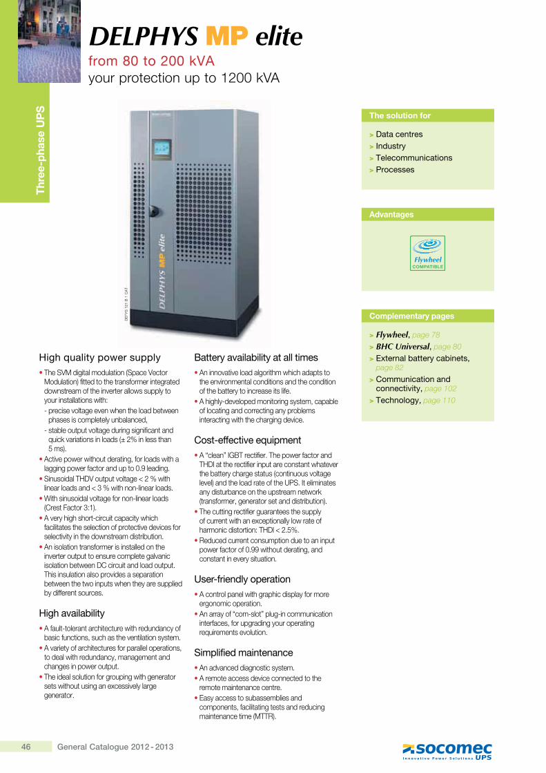
46 General Catalogue 2012 - 2013
DELPHYS MP elitefrom 80 to 200 kVAyour protection up to 1200 kVA
Thre
e-ph
ase
UP
S
High quality power supply� The SVM digital modulation (Space Vector
Modulation) fitted to the transformer integrated downstream of the inverter allows supply to your installations with:- precise voltage even when the load between
phases is completely unbalanced,- stable output voltage during significant and
quick variations in loads (± 2% in less than \���K�
� Active power without derating, for loads with a ������������ ������� �#���������
� Sinusoidal THDV output voltage < 2 % with ��������������¥Z��� [���X������������
� With sinusoidal voltage for non-linear loads >]��� ��� ��Z�"K�
� A very high short-circuit capacity which facilitates the selection of protective devices for ����� �^� ��� [������ ������� ���� ����
� An isolation transformer is installed on the inverter output to ensure complete galvanic ����� ����� �����]������ ��������� �� �This insulation also provides a separation between the two inputs when they are supplied ���������� ��������
High availability� A fault-tolerant architecture with redundancy of
��������� ��������[�� [�^�� ��� ������ ���� A variety of architectures for parallel operations,
to deal with redundancy, management and �[������������� �� �
� The ideal solution for grouping with generator sets without using an excessively large ����� ���
Battery availability at all times� An innovative load algorithm which adapts to
the environmental conditions and the condition �� [��� ��� ���������� ������
� A highly-developed monitoring system, capable of locating and correcting any problems �� ���� ���� [ [��[������^����
Cost-effective equipment���������?�|@��� ������@[��������� �����
THDI at the rectifier input are constant whatever the battery charge status (continuous voltage ��^��K��� [������� ��� [���~�? ������� ��any disturbance on the upstream network > ���������������� ���� ������ ���� ���K�
� The cutting rectifier guarantees the supply of current with an exceptionally low rate of [���������� �� ����@��?¥*�\��
� Reduced current consumption due to an input �������� ����#����� [�� ���� ���������� �� ���^����� �� ����
User-friendly operation� A control panel with graphic display for more
������������� ����� An array of “com-slot” plug-in communication
interfaces, for upgrading your operating ���������� ��^��� ����
Simplified maintenance�����^����������� ����� ���� A remote access device connected to the
���� ����� ��������� ���� Easy access to subassemblies and
components, facilitating tests and reducing ���� ������ ���>}@@�K�
The solution for
> Data centres> Industry> Telecommunications> Processes
Complementary pages
> Flywheel, page 78
> BHC Universal, page 80
> External battery cabinets, page 82
> Communication and connectivity, page 102
> Technology, page 110
Advantages
FlywheelCOMPATIBLE
DE
FYS
121
B 1
CA
T
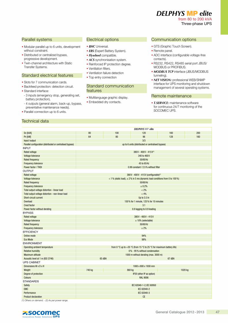
47General Catalogue 2012 - 2013
DELPHYS MP elite from 80 to 200 kVA
Three-phase UPS
� Modular parallel up to 6 units, development �� [�� ���� ���� �
� Distributed or centralized bypass, ��������^���^������� �
� Twin-channel architecture with Static @�������~�� ����
Standard electrical features
�~�� �������������� ����������|��Q������� �� ������ �� ��������� �� Standard interface:
- 3 inputs (emergency stop, generating set, battery protection),
- 4 outputs (general alarm, back-up, bypass, ���^�� � �^����� �����������K�
��������������� ����� �!��� ��
Communication options
��@~>����[��@���[~�����K������ �������� ADC interface (configurable voltage-free
��� �� �K�� RS232, RS422, RS485 serial port JBUS/
}��|�~������?|�~�� MODBUS TCP interface (JBUS/MODBUS
�������K�� NET VISION: professional WEB/SNMP
interface for UPS monitoring and shutdown �������� ����^��������� ����� ����
Remote maintenance
� T.SERVICE: maintenance software for continuous 24/7 monitoring of the ~�]�}�]��~�
Parallel systems Electrical options
� BHC���^������� EBS >����� |� ���~�� ��K�� Flywheel ����� ������ ACS����[������ ������ ��������������?���� �� ����������+�� ��� ������ ����� Ventilation failure detection� Top entry connection
Standard communication features
� }�� ����������[����������� �������������� �� ��
Technical data
DELPHYS MP eliteSn [kVA] 80 100 120 160 200Pn [kW] 64 80 96 128 160Input / output 3/3Parallel configuration (distributed or centralised bypass) up to 6 units (distributed or centralised bypass)
INPUTRated voltage 380 V - 400 V - 415 V(1)
Voltage tolerance 340 to 460 VRated frequency 50/60 HzFrequency tolerance 45 to 65 HzPower factor / THDI 0.99 constant / 2.5 % without filter
OUTPUTRated voltage 380 V - 400 V - 415 V (configurable)(1)
Voltage tolerance ����,���������&;z����� ���,&\��������&���&������Z'���������;Rated frequency 50/60 HzFrequency tolerance ��}��Total output voltage distortion - linear load < 2%Total output voltage distortion - non-linear load < 4%Short-circuit current Up to 3.5 InOverload � ��Z�'�������z�� �Z�'���������Crest factor 3:1Power factor without derating 0.9 lagging to 0.9 leading
BYPASSRated voltage 380 V - 400 V - 415 VVoltage tolerance ����,����������;Rated frequency 50/60 HzFrequency tolerance ���
EFFICIENCY��������&� 94%Eco Mode 98%
ENVIRONMENT�=�'����*����������=�'���'� Z'����!`�=��|� �!`,Z'��� �!`��� �!`Z�'��[���������'\��Z�;@�����:�����&��\ 0 % - 95 % without condensation��[����������&� ������������&�'����*,��[}�����;����������:������,^%��"�; 65 dBA �&]�
UPS CABINET>���������_[>[� ����[j��[������Weight "��* 860 kg 1020 kgDegree of protection IP20 (other IP as option)Colours RAL 9006
STANDARDSSafety ^{`���"�Q�Q�z{`��� �EMC IEC 62040-2$�'Z�'����� IEC 62040-3Product declaration CE
(1) Others on demand. - (2) As per power range.
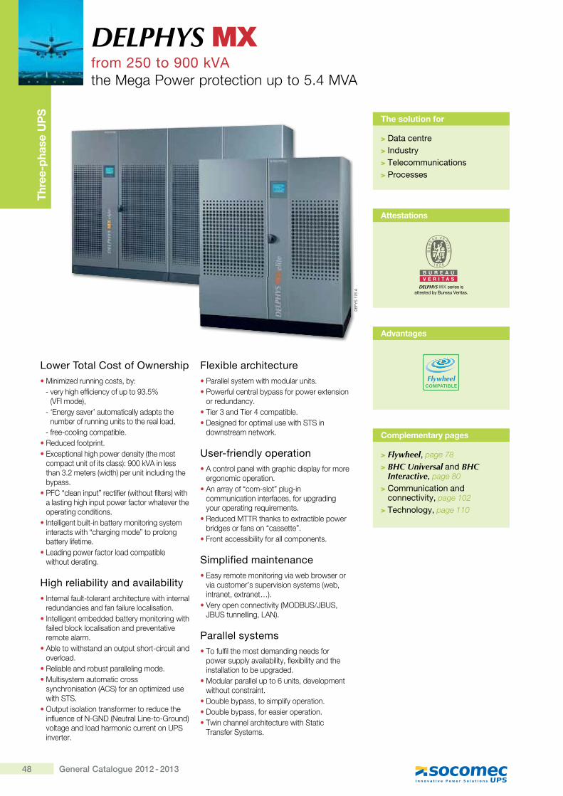
48 General Catalogue 2012 - 2013
DELPHYS MXfrom 250 to 900 kVAthe Mega Power protection up to 5.4 MVA
Thre
e-ph
ase
UP
S
Lower Total Cost of Ownership� Minimized running costs, by:
- very high efficiency of up to 93.5% >+�?�����K�
- ‘Energy saver’ automatically adapts the number of running units to the real load,
- free-cooling compatible.� Reduced footprint.� Exceptional high power density (the most
������ ��� ��� ������K��##Q+������� [��Z�*�� ���>��� [K������ �������� [�bypass.
���]���������� ���� �����>�� [�� ��� ���K�� [a lasting high input power factor whatever the operating conditions.
� Intelligent built-in battery monitoring system interacts with “charging mode” to prolong battery lifetime.
� Leading power factor load compatible without derating.
High reliability and availability� Internal fault-tolerant architecture with internal
redundancies and fan failure localisation.� Intelligent embedded battery monitoring with
����������Q�������� ���������^�� � �^�remote alarm.
� Able to withstand an output short-circuit and overload.
� Reliable and robust paralleling mode.� Multisystem automatic cross
����[������ ���>�]~K������� ���������with STS.
� Output isolation transformer to reduce the �����������_X�_�>_�� ���{���X �X������Kvoltage and load harmonic current on UPS inverter.
Flexible architecture� Parallel system with modular units.� Powerful central bypass for power extension
or redundancy.� Tier 3 and Tier 4 compatible.� Designed for optimal use with STS in
����� ������ ���Q�
User-friendly operation� A control panel with graphic display for more
ergonomic operation.� An array of “com-slot” plug-in
communication interfaces, for upgrading your operating requirements.
��������}@@� [��Q� ��� ��� ���������bridges or fans on “cassette”.
� Front accessibility for all components.
Simplified maintenance� Easy remote monitoring via web browser or
via customer’s supervision systems (web, �� ���� ��� ���� ¦K�
� Very open connectivity (MODBUS/JBUS, JBUS ���������{�_K�
Parallel systems� To fulfil the most demanding needs for
power supply availability, flexibility and the installation to be upgraded.
� Modular parallel up to 6 units, development without constraint.
� Double bypass, to simplify operation.� Double bypass, for easier operation.� Twin channel architecture with Static
Transfer Systems.
The solution for
> Data centre> Industry> Telecommunications> Processes
Complementary pages
> Flywheel, page 78
> BHC Universal and BHC Interactive, page 80
> Communication and connectivity, page 102
> Technology, page 110
DE
FYS
176
A
Attestations
B U R E A UV E R I T A S
DELPHYS MX series is attested by Bureau Veritas.
Advantages
FlywheelCOMPATIBLE
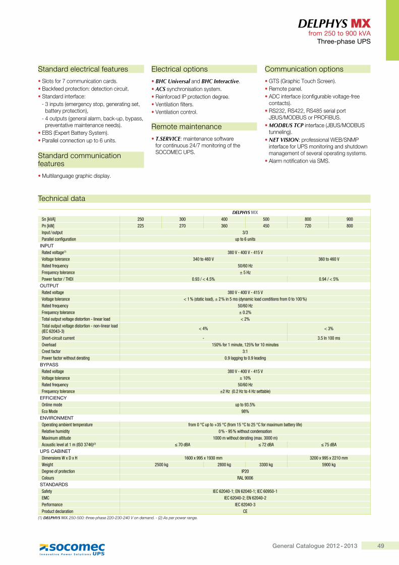
49General Catalogue 2012 - 2013
DELPHYS MX from 250 to 900 kVA
Three-phase UPS
Standard electrical features
� Slots for 7 communication cards.�|��Q������� �� ������ �� ��������� �� Standard interface:
- 3 inputs (emergency stop, generating set, �� ������ �� ���K�
X'�� �� �>���������������QX�������������^�� � �^����� �����������K�
��|~>����� |� ���~�� ��K�� Parallel connection up to 6 units.
Standard communication features
� Multilanguage graphic display.
Electrical options
� BHC Universal and BHC Interactive.� ACS synchronisation system.� Reinforced IP protection degree.� Ventilation filters.� Ventilation control.
Remote maintenance
� T.SERVICE: maintenance software for continuous 24/7 monitoring of the SOCOMEC UPS.
Communication options
��@~>����[��@���[~�����K�� Remote panel.� ADC interface (configurable voltage-free
��� �� �K�� RS232, RS422, RS485 serial port
JBUS/MODBUS or PROFIBUS.� MODBUS TCP interface (JBUS/MODBUS
�������K�� NET VISION: professional WEB/SNMP
interface for UPS monitoring and shutdown management of several operating systems.
� Alarm notification via SMS.
Technical data
DELPHYS MXSn [kVA] 250 300 400 500 800 900Pn [kW] 225 270 360 450 720 800Input / output 3/3Parallel configuration up to 6 units
INPUTRated voltage(1) 380 V - 400 V - 415 VVoltage tolerance 340 to 460 V 360 to 460 VRated frequency 50/60 HzFrequency tolerance ± 5 HzPower factor / THDI 0.93 / < 4.5% 0.94 / < 5%
OUTPUTRated voltage 380 V - 400 V - 415 VVoltage tolerance ����,���������&;z����� ���,&\��������&���&������Z'���������;Rated frequency 50/60 HzFrequency tolerance ± 0.2%Total output voltage distortion - linear load < 2%
Total output voltage distortion - non-linear load (lEC 62043-3) < 4% < 3%
Short-circuit current - �} ^������Overload � ��Z�'�������z�� �Z�'���������Crest factor 3:1Power factor without derating 0.9 lagging to 0.9 leading
BYPASSRated voltage 380 V - 400 V - 415 VVoltage tolerance ± 10%Rated frequency 50/60 HzFrequency tolerance ±2 Hz (0.2 Hz to 4 Hz settable)
EFFICIENCY��������&� up to 93.5%Eco Mode 98%
ENVIRONMENT�=�'����*����������=�'���'� Z'����!`�=��|� �!`,Z'��� �!`��� �!`Z�'��[���������'\��Z�;@�����:�����&��\ 0 % - 95 % without condensation��[����������&� ������������&�'����*,��[}�����;����������:������,^%��"�;(2) ��&]� ��&]� � &]�
UPS CABINET>���������_[>[� ����[�� [������ ����[�� [������Weight 2500 kg 2800 kg 3300 kg 5900 kgDegree of protection IP20Colours RAL 9006
STANDARDSSafety IEC 62040-1; EN 62040-1; IEC 60950-1EMC IEC 62040-2; EN 62040-2$�'Z�'����� IEC 62040-3Product declaration CE
(1) DELPHYS MX 250-500: three-phase 220-230-240 V on demand. - (2) As per power range.
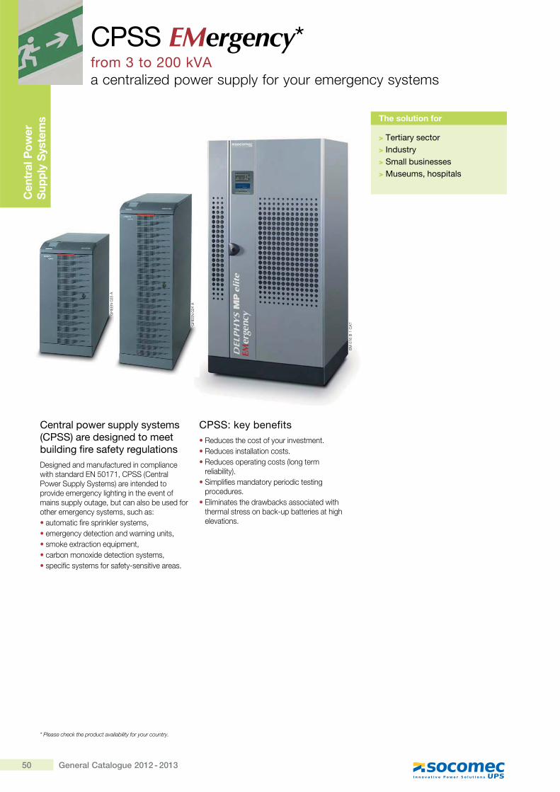
50 General Catalogue 2012 - 2013
CPSS EMergency*from 3 to 200 kVAa centralized power supply for your emergency systems
Cen
tral
Pow
er
Sup
ply
Sys
tem
s
Central power supply systems (CPSS) are designed to meet building fire safety regulations Designed and manufactured in compliance with standard EN 50171, CPSS (Central Power Supply Systems) are intended to provide emergency lighting in the event of mains supply outage, but can also be used for other emergency systems, such as:• automatic fire sprinkler systems,• emergency detection and warning units,• smoke extraction equipment,• carbon monoxide detection systems,• specific systems for safety-sensitive areas.
CPSS: key benefits• Reduces the cost of your investment.• Reduces installation costs.• Reduces operating costs (long term
reliability).• Simplifies mandatory periodic testing
procedures.• Eliminates the drawbacks associated with
thermal stress on back-up batteries at high elevations.
The solution for
> Tertiary sector> Industry> Small businesses> Museums, hospitals
EM
016
B 1
CA
T
GR
EE
N 0
25 A
GR
EE
N 0
24 A
* Please check the product availability for your country.
51General Catalogue 2012 - 2013
Batteries� VRLA (Valved Regulated Lead Acid).� Long life expectancy: 10 years operating at
20 °C.� Compliant with EN 50272-2.� Back-up time between 30 and 180 minutes.
Slow-discharge protection� Inverter shutdown function, designed to
prevent deep-discharge battery damage.� Preventive alarm and manual reset after
shutdown.
Battery charger� Compliant with EN 50272-2 and
EN 60146-1-1.� Recharge to 80 % capacity within 12 hours,
in conformity with EN 50171.� Low AC ripple currents for maximum battery
life, and in conformity with EN 50171.� Battery voltage regulated automatically
according to temperature.
Test� Automatic and manual battery test.� Input switch for mandatory periodicverification of battery back-up time.
Enclosure� Metal structure compliant with EN 60598-1.� Minimum protection category IP 20.� Compact dimensions (small footprint).
Inverter� Low harmonic distortion (THDU %) on
output side.� Protection against battery polarity inversion,
in conformity with EN 50171.
Transformers� Double wound with safety earth screen,
conforms to EN 61558-2-6 (option).
On request� Galvanic isolation transformer compliant
with EN 61558-2-6.� Prewired for isolated neutral (IT).� Permanent Isolation Controller.
Remote indicationAdvanced Dry Contact (ADC) card, availabledepending on the model selected:� Operating status.� Battery charge low.� Battery charger fault.� General alarm.� Earth leakage fault.
Local signalling� Input voltage out of tolerance.� Output voltage present.� Battery mode.� Battery circuit interrupted.� Floating voltage fault.� On battery when mains present.� Slow discharge pre-alarm.� Slow discharge protection alarm.� Charger fault.� Earth leakage fault (option).
CPSS EMergency from 3 to 200 kVA
Central Power Supply Systems
Fully compliant product ranges
The CPSS EMergency range has been developed to meet your critical needs, while ensuring compliance with European standards.
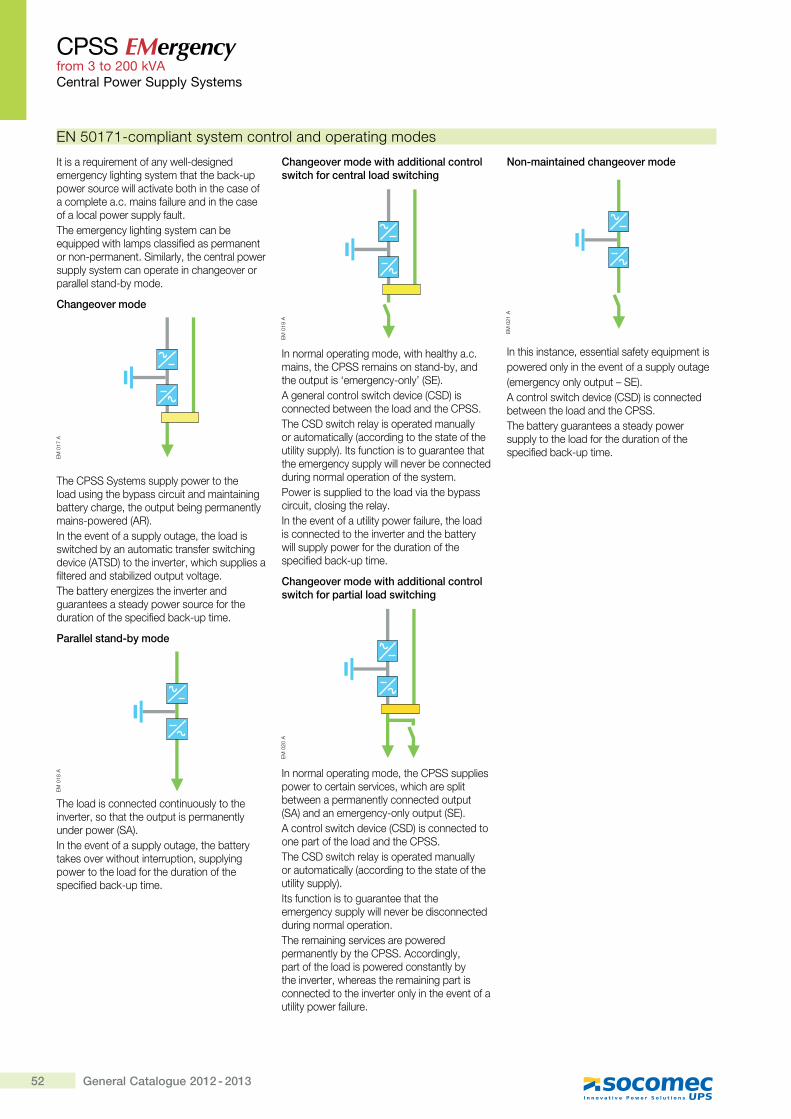
52 General Catalogue 2012 - 2013
CPSS EMergency from 3 to 200 kVACentral Power Supply Systems
It is a requirement of any well-designed emergency lighting system that the back-up power source will activate both in the case of a complete a.c. mains failure and in the case of a local power supply fault.The emergency lighting system can be equipped with lamps classified as permanent or non-permanent. Similarly, the central power supply system can operate in changeover or parallel stand-by mode.
Changeover mode
The CPSS Systems supply power to the load using the bypass circuit and maintaining battery charge, the output being permanently mains-powered (AR).In the event of a supply outage, the load is switched by an automatic transfer switching device (ATSD) to the inverter, which supplies a filtered and stabilized output voltage.The battery energizes the inverter and guarantees a steady power source for the duration of the specified back-up time.
Parallel stand-by mode
The load is connected continuously to the inverter, so that the output is permanently under power (SA).In the event of a supply outage, the battery takes over without interruption, supplying power to the load for the duration of the specified back-up time.
Changeover mode with additional control switch for central load switching
In normal operating mode, with healthy a.c. mains, the CPSS remains on stand-by, and the output is ‘emergency-only’ (SE).A general control switch device (CSD) is connected between the load and the CPSS.The CSD switch relay is operated manually or automatically (according to the state of the utility supply). Its function is to guarantee that the emergency supply will never be connected during normal operation of the system.Power is supplied to the load via the bypass circuit, closing the relay.In the event of a utility power failure, the load is connected to the inverter and the battery will supply power for the duration of the specified back-up time.
Changeover mode with additional control switch for partial load switching
In normal operating mode, the CPSS supplies power to certain services, which are split between a permanently connected output (SA) and an emergency-only output (SE).A control switch device (CSD) is connected to one part of the load and the CPSS.The CSD switch relay is operated manually or automatically (according to the state of the utility supply).Its function is to guarantee that the emergency supply will never be disconnected during normal operation.The remaining services are powered permanently by the CPSS. Accordingly, part of the load is powered constantly by the inverter, whereas the remaining part is connected to the inverter only in the event of a utility power failure.
Non-maintained changeover mode
In this instance, essential safety equipment ispowered only in the event of a supply outage(emergency only output – SE).A control switch device (CSD) is connected between the load and the CPSS.The battery guarantees a steady power supply to the load for the duration of the specified back-up time.
EN 50171-compliant system control and operating modes
EM
017
AE
M 0
18 A
EM
019
AE
M 0
20 A
EM
021
A
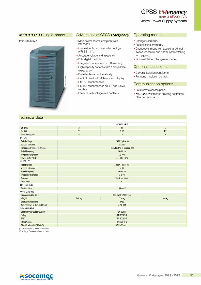
53General Catalogue 2012 - 2013
CPSS EMergency from 3 to 200 kVA
Central Power Supply Systems
Technical data
MODULYS ELSn [kVA] 3 4.5 6Pn [kW] 2.1 3.15 4.2Input / output 1/1 � � �
INPUTRated voltage 230 V (1ph + N)Voltage tolerance ± 20%Permissable voltage tolerance -30% to 70% of nominal loadRated frequency �Q�����Frequency tolerance ± 10%$���'Z����'�<�>^ ���}�j��� �
OUTPUTRated voltage 230 V (1ph + N)Voltage tolerance ± 3%Rated frequency �Q�����Frequency tolerance ± 0.1%Overload 130% for 10 secCrest factor 3:1
BATTERIESBack-up time 60 min(1)
UPS CABINET>���������_[>[� """[� [������Weight 240 kg 330 kg 340 kg>�*'���Z='�������� IP20Acoustic level at 1 m (ISO 3746) �� ��&]�
STANDARDSCentral Power Supply System EN 50171Safety EN 62040-1EMC {h ����Q�Performance IEC 62040-3Classification (IEC 62040-3) VFI(2) - SS - 111
(1) Other back-up times on request. (2) Voltage Frequency Independent.
MODULYS EL single-phase
from 3 to 6 kVA
Advantages of CPSS EMergency
� Main power source compliant with �_�\#"�"�
� Online double conversion technology (VFI-SS-111).
� Accurate voltage and frequency.� Fully digital controls.� Integrated batteries (up to 60 minutes).� High capacity batteries with a 10-year life
expectancy.� Batteries tested automatically.� Control panel with alphanumeric display.� RS 232 serial interface.� RS 485 serial interface on 4.5 and 6 kVA
models.� Interface with voltage-free contacts.
Operating modes
� Changeover mode.� Parallel stand-by mode.� Changeover mode with additional control
switch for central and partial load switching (on request).
� Non-maintained changeover mode.
Optional accessories
� Galvanic isolation transformer.� Permanent isolation control.
Communication options
� LCD remote access panel.� NET VISION interface allowing control via
Ethernet network.
EM
015
B 1
CA
T
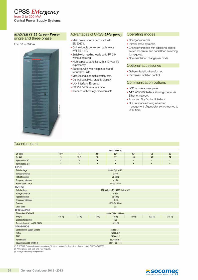
54 General Catalogue 2012 - 2013
CPSS EMergency from 3 to 200 kVACentral Power Supply Systems
Technical data
MASTERYS ELSn [kVA] 10(1) 15(1) 20(1) 30(1) 40(1) 60 j�Pn [kW] � 13.5 �j 27 36 "j 64Input / output 3/1 � � � - - - -Input / output 3/3 � � � � � � �
INPUTRated voltage "���,�=�|�h;(2)
Voltage tolerance ± 20%Rated frequency �Q�����Frequency tolerance ± 10%$���'Z����'�<�>^ ���}�������
OUTPUTRated voltage 230 V (1ph + N) - 400 V (3ph + N)(1)
Voltage tolerance ± 1%Rated frequency �Q�����Frequency tolerance ± 0.1%Overload 150% for 60 secCrest factor 3:1
UPS CABINET>���������_[>[� """[� [�"����Weight ��j�* 123 kg 126 kg 137 kg 157 kg 200 kg 210 kg>�*'���Z='�������� IP20Acoustic level at 1 m (ISO 3746) �����&]�
STANDARDSCentral Power Supply System EN 50171Safety EN 62040-1EMC {h ����Q�Performance IEC 62040-3Classification (IEC 62040-3) VFI(3) - SS - 111
(1) TÜV SÜD. Battery dimensions and weight, dependent on back-up time: please contact SOCOMEC UPS. �+��<#���$&#����++N$+GN$+_N�X������`������ (3) Voltage Frequency Independent.
MASTERYS EL Green Power single and three-phase
from 10 to 80 kVA
Advantages of CPSS EMergency
� Main power source compliant with �_�\#"�"�
� Online double conversion technology (VFI-SS-111).
� Suitable for leading loads up to PF 0.9 without derating.
� High capacity batteries with a 10-year life expectancy.
� Batteries with two independent and redundant units.
� Manual and automatic battery test.� Control panel with graphic display.� LAN interface (Ethernet).� RS 232 / 485 serial interface.� Interface with voltage-free contacts
Operating modes
� Changeover mode.� Parallel stand-by mode.� Changeover mode with additional control
switch for central and partial load switching (on request).
� Non-maintained changeover mode.
Optional accessories
� Galvanic isolation transformer.� Permanent isolation control.
Communication options
� LCD remote access panel.� NET VISION interface allowing control via
Ethernet network.� Advanced Dry Contact interface.� GSS interface allowing advanced
management of generator set connected to UPS input.
GR
EE
N 0
24 A
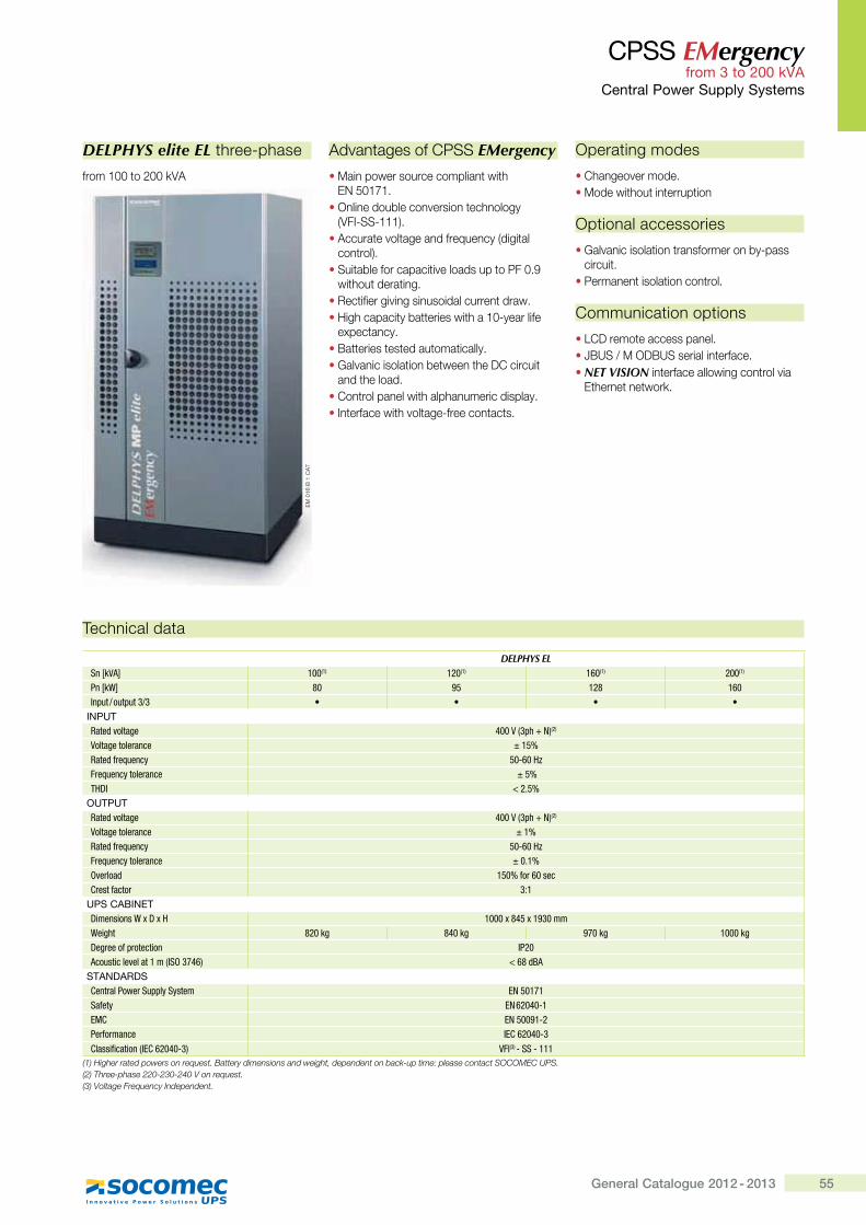
55General Catalogue 2012 - 2013
CPSS EMergency from 3 to 200 kVA
Central Power Supply Systems
Technical data
DELPHYS ELSn [kVA] 100(1) 120(1) 160(1) 200(1)
Pn [kW] j� � ��j 160Input / output 3/3 � � � �
INPUTRated voltage "���,�=�|�h;(2)
Voltage tolerance ± 15%Rated frequency �Q�����Frequency tolerance ± 5%<�>^ ���} �
OUTPUTRated voltage 400 V (3ph + N)(2)
Voltage tolerance ± 1%Rated frequency �Q�����Frequency tolerance ± 0.1%Overload 150% for 60 secCrest factor 3:1
UPS CABINET>���������_[>[� ����[j" [������Weight j���* j"��* ���* 1000 kg>�*'���Z='�������� IP20Acoustic level at 1 m (ISO 3746) ���j�&]�
STANDARDSCentral Power Supply System EN 50171Safety EN 62040-1EMC {h ����Q�Performance IEC 62040-3Classification (IEC 62040-3) VFI(3) - SS - 111
(1) Higher rated powers on request. Battery dimensions and weight, dependent on back-up time: please contact SOCOMEC UPS. �+��<#���$&#����++N$+GN$+_N�X������`����� (3) Voltage Frequency Independent.
DELPHYS elite EL three-phase
from 100 to 200 kVA
Advantages of CPSS EMergency
� Main power source compliant with �_�\#"�"�
� Online double conversion technology (VFI-SS-111).
� Accurate voltage and frequency (digital control).
� Suitable for capacitive loads up to PF 0.9 without derating.
� Rectifier giving sinusoidal current draw.� High capacity batteries with a 10-year life
expectancy.� Batteries tested automatically.� Galvanic isolation between the DC circuit
and the load.� Control panel with alphanumeric display.� Interface with voltage-free contacts.
Operating modes
� Changeover mode.� Mode without interruption
Optional accessories
� Galvanic isolation transformer on by-pass circuit.
� Permanent isolation control.
Communication options
� LCD remote access panel.� JBUS / M ODBUS serial interface.� NET VISION interface allowing control via
Ethernet network.
EM
016
B 1
CA
T
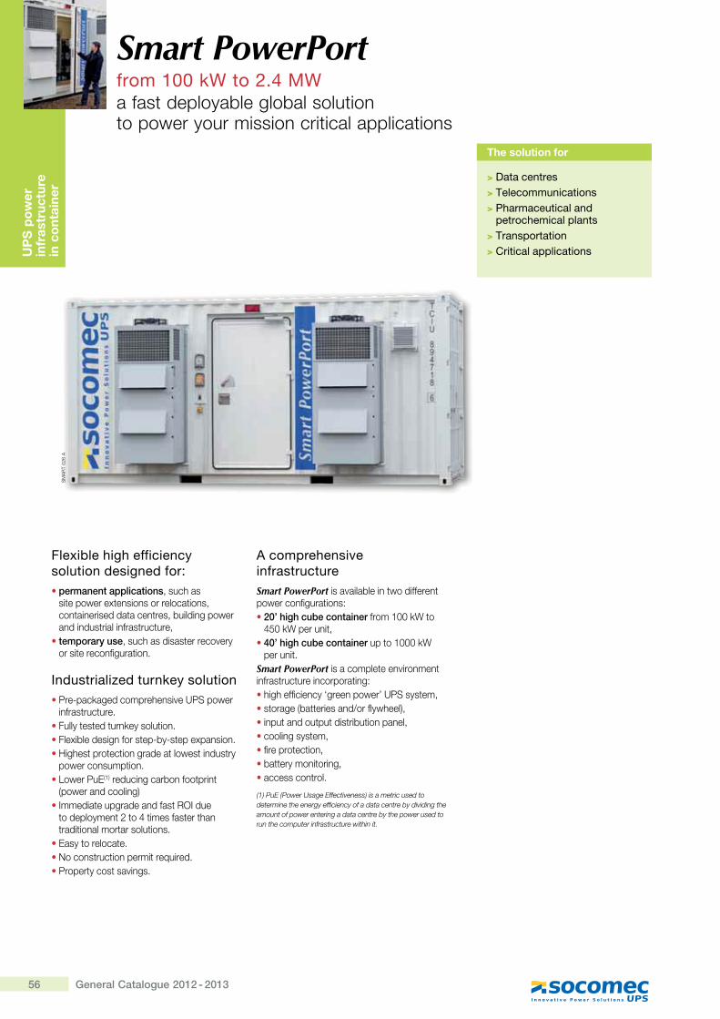
56 General Catalogue 2012 - 2013
Smart PowerPortfrom 100 kW to 2.4 MWa fast deployable global solution to power your mission critical applications
UP
S p
ow
er
infr
astr
uctu
re
in c
ont
aine
r
The solution for
> Data centres> Telecommunications> Pharmaceutical and
petrochemical plants> Transportation> Critical applications
Flexible high efficiency solution designed for:� permanent applications, such as
site power extensions or relocations, containerised data centres, building power and industrial infrastructure,
� temporary use, such as disaster recovery or site reconfiguration.
Industrialized turnkey solution�Pre-packaged comprehensive UPS power
infrastructure.�Fully tested turnkey solution.�Flexible design for step-by-step expansion.�Highest protection grade at lowest industry
power consumption.�Lower PuE(1) reducing carbon footprint
(power and cooling)�Immediate upgrade and fast ROI due
to deployment 2 to 4 times faster than traditional mortar solutions.
�Easy to relocate.�No construction permit required.�Property cost savings.
A comprehensive infrastructureSmart PowerPort is available in two different power configurations:�20’ high cube container from 100 kW to
450 kW per unit,�40’ high cube container up to 1000 kW
per unit.Smart PowerPort is a complete environment infrastructure incorporating:�high efficiency ‘green power’ UPS system,�storage (batteries and/or flywheel),�input and output distribution panel,�cooling system,�fire protection,�battery monitoring,�access control.
(1) PuE (Power Usage Effectiveness) is a metric used to determine the energy efficiency of a data centre by dividing the amount of power entering a data centre by the power used to run the computer infrastructure within it.
SM
AR
T 02
6 A
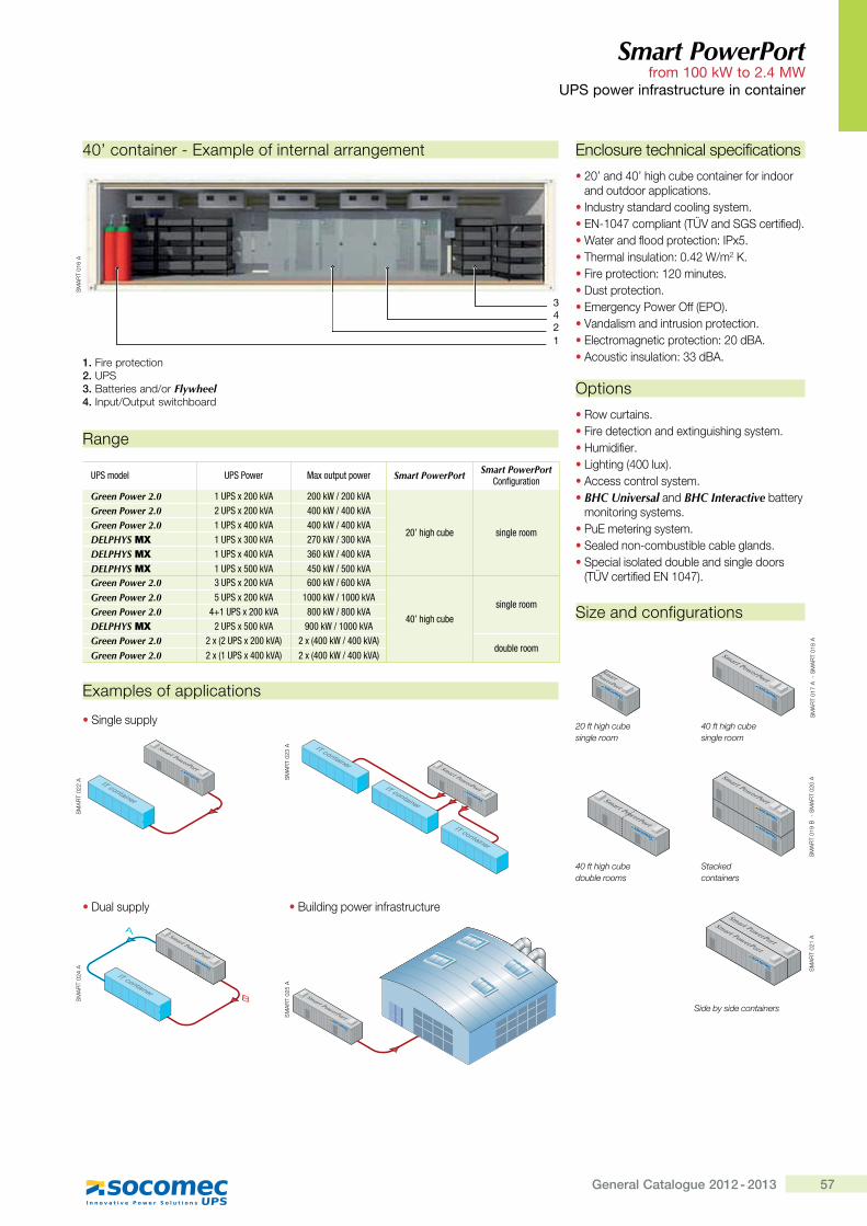
57General Catalogue 2012 - 2013
Smart PowerPort from 100 kW to 2.4 MW
UPS power infrastructure in container
Examples of applications
Range
40’ container - Example of internal arrangement
Size and configurations
Enclosure technical specifications
�20’ and 40’ high cube container for indoor and outdoor applications.
�Industry standard cooling system.�EN-1047 compliant (TÜV and SGS certified).�Water and flood protection: IPx5.�Thermal insulation: 0.42 W/m2 K.�Fire protection: 120 minutes.�Dust protection.�Emergency Power Off (EPO).�Vandalism and intrusion protection.�Electromagnetic protection: 20 dBA.�Acoustic insulation: 33 dBA.
Options
�Row curtains.�Fire detection and extinguishing system.�Humidifier.�Lighting (400 lux).�Access control system.� BHC Universal and BHC Interactive battery
monitoring systems.�PuE metering system.�Sealed non-combustible cable glands.�Special isolated double and single doors
(TÜV certified EN 1047).
UPS model UPS Power Max output power Smart PowerPort Smart PowerPort Configuration
Green Power 2.0 1 UPS x 200 kVA 200 kW / 200 kVA
20’ high cube single room
Green Power 2.0 2 UPS x 200 kVA 400 kW / 400 kVAGreen Power 2.0 1 UPS x 400 kVA 400 kW / 400 kVADELPHYS MX 1 UPS x 300 kVA 270 kW / 300 kVADELPHYS MX 1 UPS x 400 kVA 360 kW / 400 kVA
DELPHYS MX 1 UPS x 500 kVA 450 kW / 500 kVAGreen Power 2.0 3 UPS x 200 kVA 600 kW / 600 kVA
40’ high cubesingle room
Green Power 2.0 5 UPS x 200 kVA 1000 kW / 1000 kVAGreen Power 2.0 4+1 UPS x 200 kVA 800 kW / 800 kVADELPHYS MX 2 UPS x 500 kVA 900 kW / 1000 kVAGreen Power 2.0 2 x (2 UPS x 200 kVA) 2 x (400 kW / 400 kVA)
double roomGreen Power 2.0 2 x (1 UPS x 400 kVA) 2 x (400 kW / 400 kVA)
�Single supply
�Dual supply �Building power infrastructure
20 ft high cubesingle room
40 ft high cubesingle room
40 ft high cubedouble rooms
Stackedcontainers
Side by side containers
SmartPowerPort
Smart PowerPort
SM
AR
T 01
7 A
-
SM
AR
T 01
8 A
Smart PowerPort
Smart PowerPortS
MA
RT
019
B
- S
MA
RT
020
A
Smart PowerPort
Smart PowerPort
SM
AR
T 02
1 A
Smart PowerPort
IT container
SM
AR
T 02
2 A
Smart PowerPort
IT container
IT container
IT container
SM
AR
T 02
3 A
Smart PowerPort
IT container
Smart PowerPort
Smart PowerPort
SM
AR
T 02
4 A
Smart PowerPortSM
AR
T 02
5 A
SM
AR
T 01
6 A
421
3
1. Fire protection2. UPS3. Batteries and/or Flywheel4. Input/Output switchboard
General Catalogue 2012 - 2013
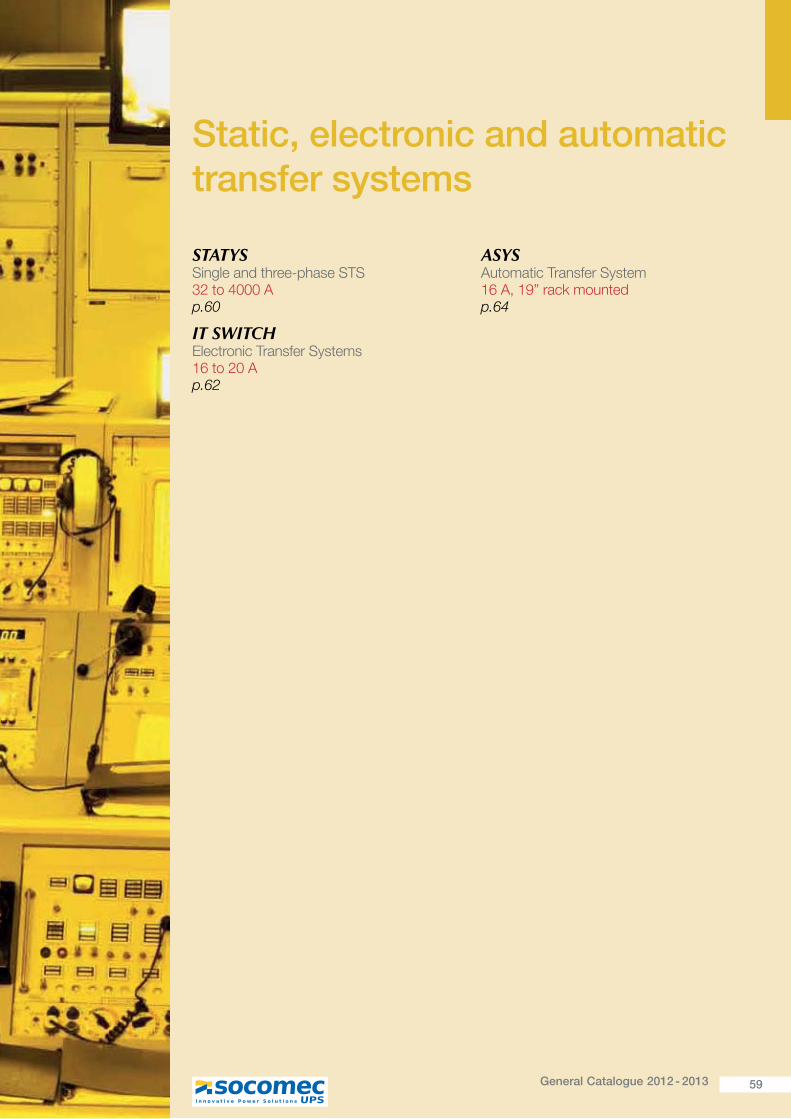
59General Catalogue 2012 - 2013
Static, electronic and automatic transfer systems
STATYS Single and three-phase STS 32 to 4000 A p.60
IT SWITCH Electronic Transfer Systems 16 to 20 A p.62
ASYS Automatic Transfer System 16 A, 19” rack mounted p.64
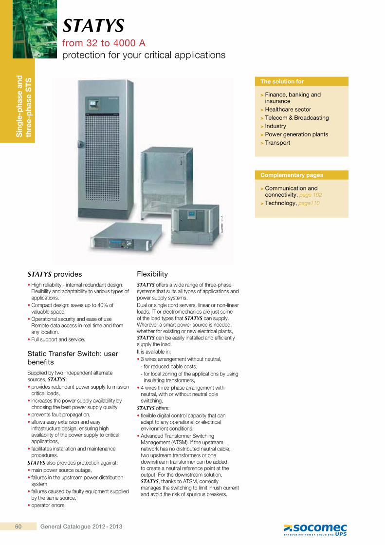
Thr
ee-p
hase
UP
S
syst
em
60 General Catalogue 2012 - 2013
STATYSfrom 32 to 4000 Aprotection for your critical applications
Sin
gle-
phas
e an
d th
ree-
phas
e S
TS
STATYS provides� High reliability - internal redundant design.
Flexibility and adaptability to various types of applications.
� Compact design: saves up to 40% of valuable space.
� Operational security and ease of use Remote data access in real time and from any location.
� Full support and service.
Static Transfer Switch: user benefitsSupplied by two independent alternate sources, STATYS:� provides redundant power supply to mission
critical loads,� increases the power supply availability by
choosing the best power supply quality� prevents fault propagation,� allows easy extension and easy
infrastructure design, ensuring high availability of the power supply to critical applications,
� facilitates installation and maintenance procedures.
STATYS also provides protection against:� main power source outage,� failures in the upstream power distribution
system,� failures caused by faulty equipment supplied
by the same source,� operator errors.
FlexibilitySTATYS offers a wide range of three-phase systems that suits all types of applications and power supply systems.Dual or single cord servers, linear or non-linear loads, IT or electromechanics are just some of the load types that STATYS can supply. Wherever a smart power source is needed, whether for existing or new electrical plants, STATYS can be easily installed and efficiently supply the load.It is available in:� 3 wires arrangement without neutral,
- for reduced cable costs,- for local zoning of the applications by using
insulating transformers,� 4 wires three-phase arrangement with
neutral, with or without neutral pole switching,
STATYS offers:� flexible digital control capacity that can
adapt to any operational or electrical environment conditions,
� Advanced Transformer Switching Management (ATSM). If the upstream network has no distributed neutral cable, two upstream transformers or one downstream transformer can be added to create a neutral reference point at the output. For the downstream solution, STATYS, thanks to ATSM, correctly manages the switching to limit inrush current and avoid the risk of spurious breakers.
The solution for
> Finance, banking and insurance
> Healthcare sector> Telecom & Broadcasting> Industry> Power generation plants> Transport
Complementary pages
> Communication and connectivity, page 102
> Technology, page110
GA
MM
E 1
01 A
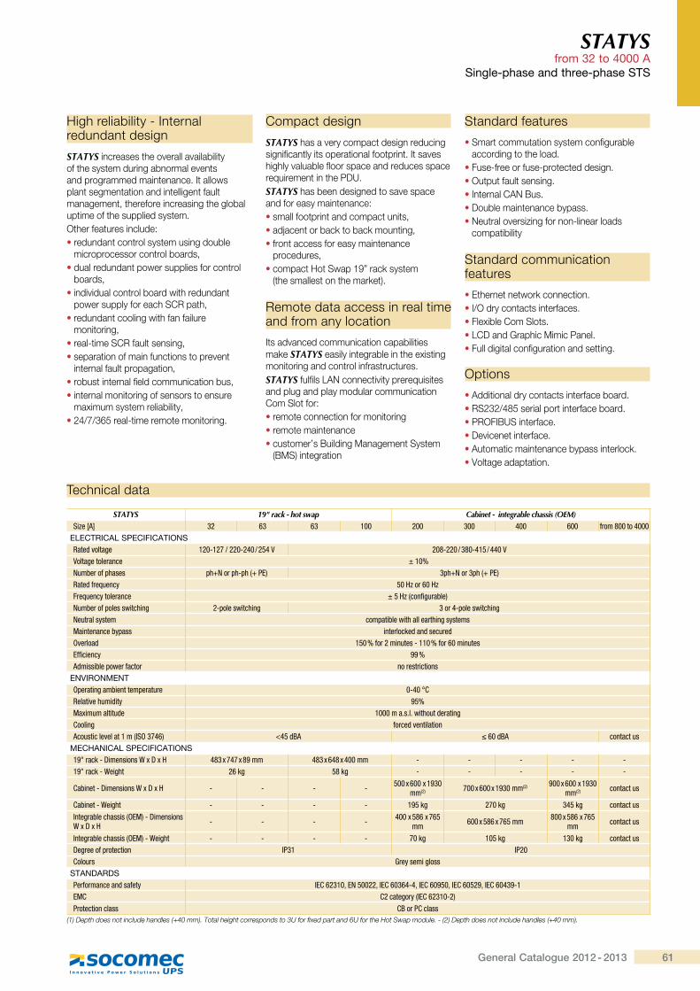
61General Catalogue 2012 - 2013
Compact design
STATYS has a very compact design reducing significantly its operational footprint. It saves highly valuable floor space and reduces space requirement in the PDU.STATYS has been designed to save space and for easy maintenance:� small footprint and compact units,� adjacent or back to back mounting,� front access for easy maintenance
procedures,� compact Hot Swap 19” rack system
(the smallest on the market).
Remote data access in real time and from any location
Its advanced communication capabilities make STATYS easily integrable in the existing monitoring and control infrastructures.STATYS fulfils LAN connectivity prerequisites and plug and play modular communication Com Slot for: � remote connection for monitoring � remote maintenance� customer’s Building Management System
(BMS) integration
High reliability - Internal redundant design
STATYS increases the overall availability of the system during abnormal events and programmed maintenance. It allows plant segmentation and intelligent fault management, therefore increasing the global uptime of the supplied system.Other features include:� redundant control system using double
microprocessor control boards,� dual redundant power supplies for control
boards,� individual control board with redundant
power supply for each SCR path,� redundant cooling with fan failure
monitoring,� real-time SCR fault sensing,� separation of main functions to prevent
internal fault propagation,� robust internal field communication bus,� internal monitoring of sensors to ensure
maximum system reliability,� 24/7/365 real-time remote monitoring.
STATYS from 32 to 4000 A
Single-phase and three-phase STS
Standard features
� Smart commutation system configurable according to the load.
� Fuse-free or fuse-protected design.� Output fault sensing.� Internal CAN Bus.� Double maintenance bypass.� Neutral oversizing for non-linear loads
compatibility
Standard communication features
� Ethernet network connection.� I/O dry contacts interfaces.� Flexible Com Slots.� LCD and Graphic Mimic Panel.� Full digital configuration and setting.
Options
� Additional dry contacts interface board.� RS232/485 serial port interface board.� PROFIBUS interface.� Devicenet interface.� Automatic maintenance bypass interlock.� Voltage adaptation.
Technical data
STATYS 19" rack - hot swap Cabinet - integrable chassis (OEM)Size [A] 32 63 63 100 200 300 400 600 from 800 to 4000
ELECTRICAL SPECIFICATIONSRated voltage 120-127 / 220-240 / 254 V 208-220 / 380-415 / 440 VVoltage tolerance ± 10%Number of phases =�|h�'=�Q=�,|�${; �=�|h�'�=�,|�${;Rated frequency 50 Hz or 60 HzFrequency tolerance � ��,���Z�*�'����;Number of poles switching 2-pole switching 3 or 4-pole switchingNeutral system compatible with all earthing systemsMaintenance bypass interlocked and securedOverload 150 % for 2 minutes - 110 % for 60 minutes{ZZ������\ 99 %Admissible power factor no restrictions
ENVIRONMENTOperating ambient temperature �Q"��!`Relative humidity 95%Maximum altitude �������}�}�}�������&�'����*`�����* forced ventilation����������:������,^%��"�; �" �&]� �����&]� contact us
MECHANICAL SPECIFICATIONS19" rack - Dimensions W x D x H 483 x 747 x 89 mm 483 x 648 x 400 mm - - - - -19" rack - Weight 26 kg 58 kg - - - - -
`������Q>���������_[>[� - - - - 500 x 600 x 1930 mm,�; 700 x 600 x 1930 mm,�; 900 x 600 x 1930
mm,�; contact us
`������Q_��*�� - - - - 195 kg 270 kg 345 kg contact us
^���*'�����������,�{�;Q>���������W x D x H - - - - 400 x 586 x 765
mm 600 x 586 x 765 mm 800 x 586 x 765 mm contact us
^���*'�����������,�{�;Q_��*�� - - - - 70 kg 105 kg 130 kg contact usDegree of protection ^$�� ^$��`����'� Grey semi gloss
STANDARDS$�'Z�'�������&��Z��\ ^{`�����z{h ����z^{`����"Q"z^{`��� �z^{`�� ��z^{`��"��Q�{�` `�����*�'\,^{`�����Q�;$'������������� `]�'$`�����
���� �&�#�Y�������������Y��#��Y�����_N������<�����#��"#��������&��Y�����Gj�'���'�{�Y�&������Y�|j�'����#��=���}~�&���Y�����$��+�� �&�#�Y�������������Y��#��Y�����_N�����
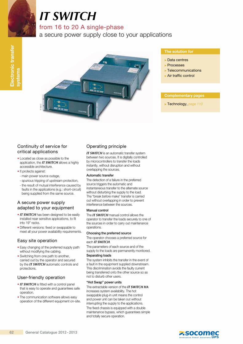
Thr
ee-p
hase
UP
S
syst
em
62 General Catalogue 2012 - 2013
IT SWITCHfrom 16 to 20 A single-phasea secure power supply close to your applications
Ele
ctro
nic
tran
sfer
sy
stem
s
Continuity of service for critical applications� Located as close as possible to the
application, the IT SWITCH allows a highly accessible architecture.
� It protects against:- main power source outage,- spurious tripping of upstream protection,- the result of mutual interference caused by
faults in the applications (e.g.: short-circuit) being supplied from the same source.
A secure power supply adapted to your equipment� IT SWITCH has been designed to be easily
installed near sensitive applications, to fit into 19” racks.
� Different versions: fixed or swappable to meet all your power availability requirements.
Easy site operation� Easy changing of the preferred supply path
without modifying the cabling.� Switching from one path to another,
carried out by the operator and secured by the IT SWITCH automatic controls and protections.
User-friendly operation� IT SWITCH is fitted with a control panel
that is easy to operate and guarantees safe operation.
� The communication software allows easy operation of the different equipment on-site.
Operating principleIT SWITCH is an automatic transfer system between two sources. It is digitally controlled by microcontrollers to transfer the loads instantly, without disruption and without overlapping the sources.
Automatic transferThe detection of a failure in the preferred source triggers the automatic and instantaneous transfer to the alternate source without disturbing the supply to the load. The “break before make” transfer is carried out without overlapping in order to prevent interference between the sources.
Manual controlThe IT SWITCH manual control allows the operator to transfer the loads securely to one of the sources in order to carry out maintenance operations.
Choosing the preferred sourceThe operator chooses a preferred source for each IT SWITCH.The parameters of each source and of the supply to the loads are permanently monitored.Separating loadsThe system inhibits the transfer in the event of a fault in the equipment supplied downstream. This discrimination avoids the faulty current being transferred onto the other source so as not to disturb other users.
“Hot Swap” power unitsThe extractable version of the IT SWITCH HA increases system availability. The hot swappable plug-in unit means the control and power unit can be taken out without interrupting the supply to the applications.The fixed chassis is equipped with a double maintenance bypass, which guarantees simple and totally secure operation.
The solution for
> Data centres> Processes> Telecommunications> Air traffic control
IT 0
30 C
Complementary pages
> Technology, page 110
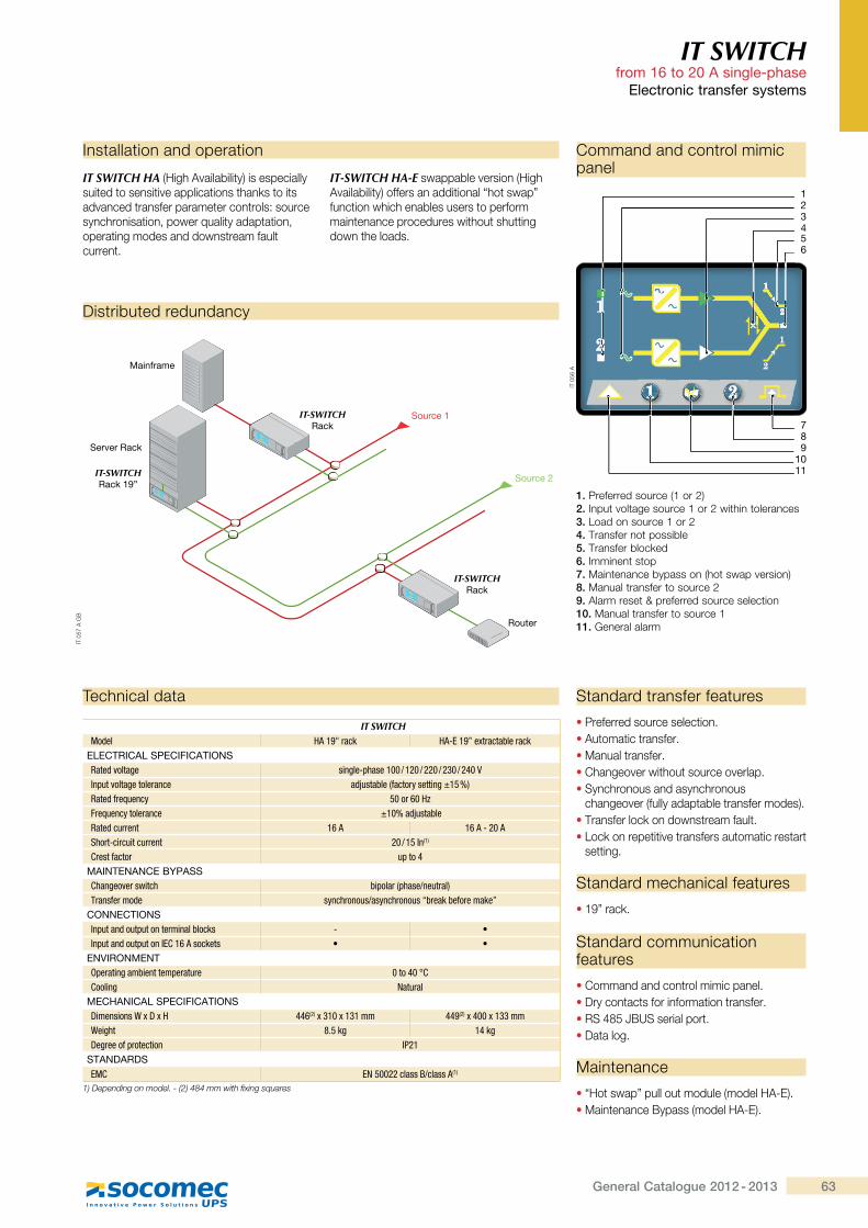
63General Catalogue 2012 - 2013
IT SWITCH from 16 to 20 A single-phase
Electronic transfer systems
Technical data
IT SWITCHModel HA 19" rack HA-E 19” extractable rack
ELECTRICAL SPECIFICATIONSRated voltage single-phase 100 / 120 / 220 / 230 / 240 VInput voltage tolerance adjustable (factory setting ±15 %)Rated frequency ��'�����Frequency tolerance ±10% adjustable Rated current 16 A 16 A - 20 AShort-circuit current 20 / 15 In(1)
Crest factor up to 4MAINTENANCE BYPASSChangeover switch bipolar (phase/neutral)Transfer mode synchronous/asynchronous “break before make”
CONNECTIONSInput and output on terminal blocks - �Input and output on IEC 16 A sockets � �
ENVIRONMENTOperating ambient temperature ���"��!`Cooling Natural
MECHANICAL SPECIFICATIONSDimensions W x D x H 446(2) x 310 x 131 mm 449(2) x 400 x 133 mmWeight 8.5 kg 14 kgDegree of protection IP21
STANDARDSEMC EN 50022 class B/class A(1)
1) Depending on model. - (2) 484 mm with fixing squares
Standard transfer features
� Preferred source selection.� Automatic transfer.� Manual transfer.� Changeover without source overlap.� Synchronous and asynchronous
changeover (fully adaptable transfer modes).� Transfer lock on downstream fault.� Lock on repetitive transfers automatic restart
setting.
Standard mechanical features
� 19” rack.
Standard communication features
� Command and control mimic panel.� Dry contacts for information transfer.� RS 485 JBUS serial port.� Data log.
Maintenance
� “Hot swap” pull out module (model HA-E).� Maintenance Bypass (model HA-E).
IT 0
57 A
GB
Mainframe
Server Rack
IT-SWITCHRack 19”
IT-SWITCHRack
Router
IT-SWITCHRack
Source 1
Source 2
Distributed redundancy
Command and control mimic panel
IT SWITCH HA (High Availability) is especially suited to sensitive applications thanks to its advanced transfer parameter controls: source synchronisation, power quality adaptation, operating modes and downstream fault current.
IT-SWITCH HA-E swappable version (High Availability) offers an additional “hot swap” function which enables users to perform maintenance procedures without shutting down the loads.
Installation and operation
1. Preferred source (1 or 2)2. Input voltage source 1 or 2 within tolerances3. Load on source 1 or 24. Transfer not possible5. Transfer blocked6. Imminent stop7. Maintenance bypass on (hot swap version)8. Manual transfer to source 29. Alarm reset & preferred source selection10. Manual transfer to source 111. General alarm
IT 0
56 A
456
789
1011
123
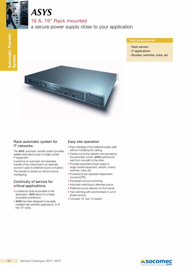
Thr
ee-p
hase
UP
S
syst
em
64 General Catalogue 2012 - 2013
ASYS16 A, 19” Rack mounteda secure power supply close to your application
Aut
omat
ic T
rans
fer
Sys
tem
Rack automatic system for IT networksThe ASYS automatic transfer system provides reliable redundant power to single corded ?@��������� �It performs an automatic and seamless transfer of the critical load to an alternate ����������������������������������� ����The transfer is carried out without source �^���������
Continuity of service for critical applications� Located as close as possible to the
application, ASYS allows for a highly �������������[� �� ����
� ASYS has been designed to be easily installed near sensitive applications, to fit �� �"�����Q��
Easy site operation� Easy changing of the preferred supply path
�� [�� �������� [��������� Carried out by the operator and secured by
the automatic control, ASYS switches the ������������� [ � [�� [���
� Provides redundant power supply to ������������������� ����^������� ������� �[���[����� ��
� Powered by two separate independent �������>��~K�
��������� ���������� �������� ��� ����� �[�� ��� ���� ����������������������������� ��������� ������� Fast switching with synchronised or out of
�[������������ Compact 19” rack 1U system
Your protection for
> Rack servers> IT applications> Routers, switches, hubs, etc
ASYS
006
A
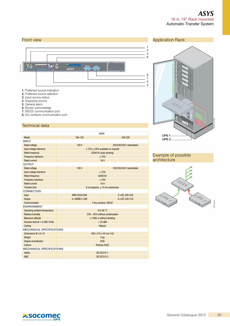
65General Catalogue 2012
ASYS 16 A, 19” Rack mounted
Automatic Transfer System
Technical data
ASYSModel 16A-120 16A-230
INPUTRated voltage 120 V 220/230/240 V (selectable)Input voltage tolerance ± 12% (± 20% available on request)Rated frequency 50/60 Hz (auto sensing)Frequency tolerance ± 15%Rated current 16 A
OUTPUTRated voltage 120 V 220/230/240 V (selectable)Input voltage tolerance ± 12%Rated frequency 50/60 HzFrequency tolerance ± 15%Rated current 16 ATransfer time ���,�\=����;z�� ��,��[����;
CONNECTIONInput AWG12X3C/20A �[^{`���Q`��Output "[h{�� Q��@ 6[^{`���Q`��Communication 5 dry contacts, RS232
ENVIRONMENTOperating ambient temperature 0 to 40 °CRelative humidity 20% - 85% without condensation��[����������&� �������������&�'����*Acoustic level at 1 m (ISO 3746) < 25 dBACooling h���'��
MECHANICAL SPECIFICATIONS>���������_[>[� "��[�� [""��,�#;Weight 5 kgDegree of protection IP30Colours Pantone 432C
MECHANICAL SPECIFICATIONSSafety ^{`�����Q�{�` ^{`�����Q�
Front view
Example of possible architecture
Application Rack
1. Preferred source indication2. Preferred source selection3. Input source status4. Supplying source5. General alarm6. Buzzer acknowledge7. RS232 communication port8. Dry contacts communication port
RS232
ASYS
1
2
ASYS
003
A
6
7
ASYS
5
ASYSASYS
3
4
RS232
2
11
1
8
UPS 1UPS 2
RS232
ASYS
1
2
ASYS
�����
ASYS
1
2
POWERSOURCE 2
POWERSOURCE 1
ASYS
UPS 1UPS 2
ASYS
010
A G
BAS
YS 0
09 A

67General Catalogue 2012 - 2013
��� �����from 15 to 600 A
SHARYS IP Industrial DC Power Station 15 to 200 A p.68
SHARYS MICRO and SHARYS MINI ��� ����� 30 to 200 A p.72
SHARYS ELITE ��� ����� 30 to 600 A p.80
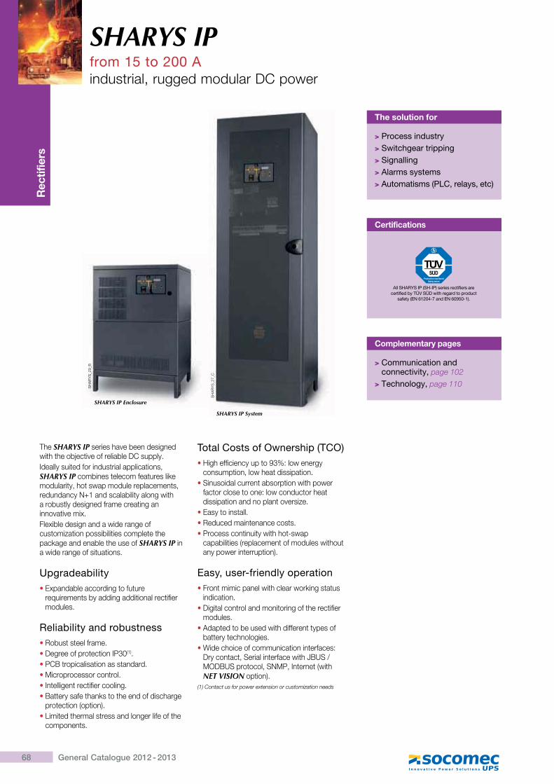
68 General Catalogue 2012 - 2013
SHARYS IPfrom 15 to 200 Aindustrial, rugged modular DC power
Rec
tifie
rs
The solution for
> Process industry> Switchgear tripping> Signalling> Alarms systems> Automatisms (PLC, relays, etc)
The SHARYS IP series have been designed with the objective of reliable DC supply.Ideally suited for industrial applications, SHARYS IP combines telecom features like modularity, hot swap module replacements, redundancy N+1 and scalability along with a robustly designed frame creating an innovative mix.Flexible design and a wide range of customization possibilities complete the package and enable the use of SHARYS IP in a wide range of situations.
Upgradeability�Expandable according to future
requirements by adding additional rectifier modules.
Reliability and robustness�Robust steel frame.�Degree of protection IP30(1).�PCB tropicalisation as standard.�Microprocessor control.�Intelligent rectifier cooling.�Battery safe thanks to the end of discharge
protection (option).�Limited thermal stress and longer life of the
components.
Total Costs of Ownership (TCO)�High efficiency up to 93%: low energy
consumption, low heat dissipation.�Sinusoidal current absorption with power
factor close to one: low conductor heat dissipation and no plant oversize.
�Easy to install.�Reduced maintenance costs.�Process continuity with hot-swap
capabilities (replacement of modules without any power interruption).
Easy, user-friendly operation�Front mimic panel with clear working status
indication.�Digital control and monitoring of the rectifier
modules.�Adapted to be used with different types of
battery technologies.�Wide choice of communication interfaces:
Dry contact, Serial interface with JBUS / MODBUS protocol, SNMP, Internet (with NET VISION option).
(1) Contact us for power extension or customization needs
Complementary pages
> Communication and connectivity, page 102
> Technology, page 110
SH
AR
YS
_27_
C
SH
AR
YS
_29_
B
Certifications
All SHARYS IP (SH-IP) series rectifiers are certified by TÜV SÜD with regard to product
safety (EN 61204-7 and EN 60950-1).
SHARYS IP Enclosure
SHARYS IP System
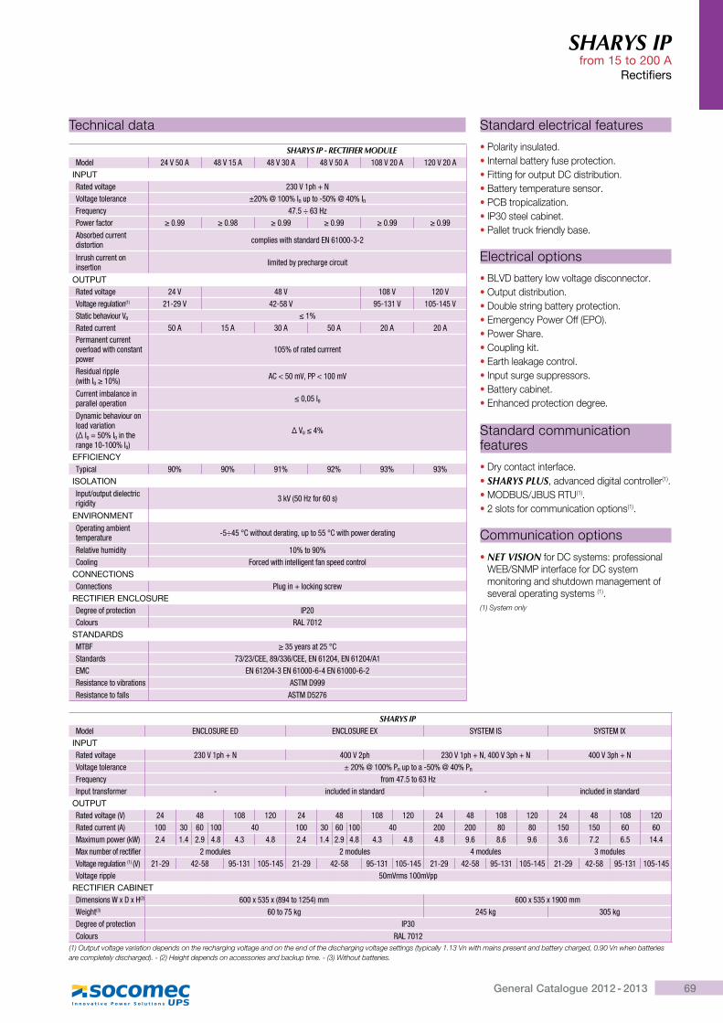
69General Catalogue 2012 - 2013
SHARYS IP from 15 to 200 A
Rectifiers
Standard electrical features
�Polarity insulated.�Internal battery fuse protection.�Fitting for output DC distribution.�Battery temperature sensor.�PCB tropicalization.�IP30 steel cabinet.�Pallet truck friendly base.
Electrical options
�BLVD battery low voltage disconnector.�Output distribution.�Double string battery protection.�Emergency Power Off (EPO).�Power Share.�Coupling kit.�Earth leakage control.�Input surge suppressors.�Battery cabinet.�Enhanced protection degree.
Standard communication features
�Dry contact interface.�SHARYS PLUS, advanced digital controller(1).�MODBUS/JBUS RTU(1).�2 slots for communication options(1).
Communication options
�NET VISION for DC systems: professional WEB/SNMP interface for DC system monitoring and shutdown management of several operating systems (1).
(1) System only
Technical data
SHARYS IP - RECTIFIER MODULEModel 24 V 50 A 48 V 15 A 48 V 30 A 48 V 50 A 108 V 20 A 120 V 20 A
INPUTRated voltage 230 V 1ph + NVoltage tolerance ±20% @ 100% In up to -50% @ 40% InFrequency 47.5 ÷ 63 HzPower factor ¤�}�� ¤�}�j ¤�}�� ¤�}�� ¤�}�� ¤�}��
Absorbed current distortion complies with standard EN 61000-3-2
Inrush current on insertion limited by precharge circuit
OUTPUTRated voltage 24 V 48 V 108 V 120 VVoltage regulation(1) ��Q��� 42-58 V � Q���� 105-145 VStatic behaviour Vo ���Rated current 50 A 15 A 30 A 50 A 20 A 20 APermanent current overload with constant power
105% of rated currrent
Residual ripple (with Io¤���; AC < 50 mV, PP < 100 mV
Current imbalance in parallel operation ��z� ^o
Dynamic behaviour on load variation,¥^o = 50% Io in the range 10-100% Io)
¥�o�"�
EFFICIENCYTypical ��� ��� ��� ��� ��� ���
ISOLATIONInput/output dielectric rigidity 3 kV (50 Hz for 60 s)
ENVIRONMENTOperating ambient temperature -5÷45 °C without derating, up to 55 °C with power derating
Relative humidity ��������Cooling Forced with intelligent fan speed control
CONNECTIONSConnections Plug in + locking screw
RECTIFIER ENCLOSUREDegree of protection IP20Colours RAL 7012
STANDARDSMTBF ¤� \��'���� !`Standards �����`{{zj������`{{z{h����"z{h����"���EMC EN 61204-3 EN 61000-6-4 EN 61000-6-2Resistance to vibrations �%<�>���Resistance to falls ASTM D5276
SHARYS IP Model ENCLOSURE ED ENCLOSURE EX SYSTEM IS SYSTEM IX
INPUTRated voltage 230 V 1ph + N 400 V 2ph 230 V 1ph + N, 400 V 3ph + N 400 V 3ph + NVoltage tolerance ± 20% @ 100% Pn up to a -50% @ 40% Pn
Frequency from 47.5 to 63 HzInput transformer - included in standard - included in standard
OUTPUTRated voltage (V) 24 48 108 120 24 48 108 120 24 48 108 120 24 48 108 120Rated current (A) 100 30 60 100 40 100 30 60 100 40 200 200 80 80 150 150 60 60Maximum power (kW) 2.4 1.4 �}� 4.8 4.3 4.8 2.4 1.4 �}� 4.8 4.3 4.8 4.8 �}� 8.6 �}� 3.6 7.2 6.5 14.4Max number of rectifier 2 modules 2 modules 4 modules 3 modulesVoltage regulation (1) (V) ��Q�� 42-58 � Q��� 105-145 ��Q�� 42-58 � Q��� 105-145 ��Q�� 42-58 � Q��� 105-145 ��Q�� 42-58 � Q��� 105-145Voltage ripple 50mVrms 100mVpp
RECTIFIER CABINETDimensions W x D x H(2) ���[ � [,j�"���� ";�� ���[ � [������Weight(3) 60 to 75 kg 245 kg 305 kgDegree of protection IP30Colours RAL 7012
(1) Output voltage variation depends on the recharging voltage and on the end of the discharging voltage settings (typically 1.13 Vn with mains present and battery charged, 0.90 Vn when batteries are completely discharged). - (2) Height depends on accessories and backup time. - (3) Without batteries.
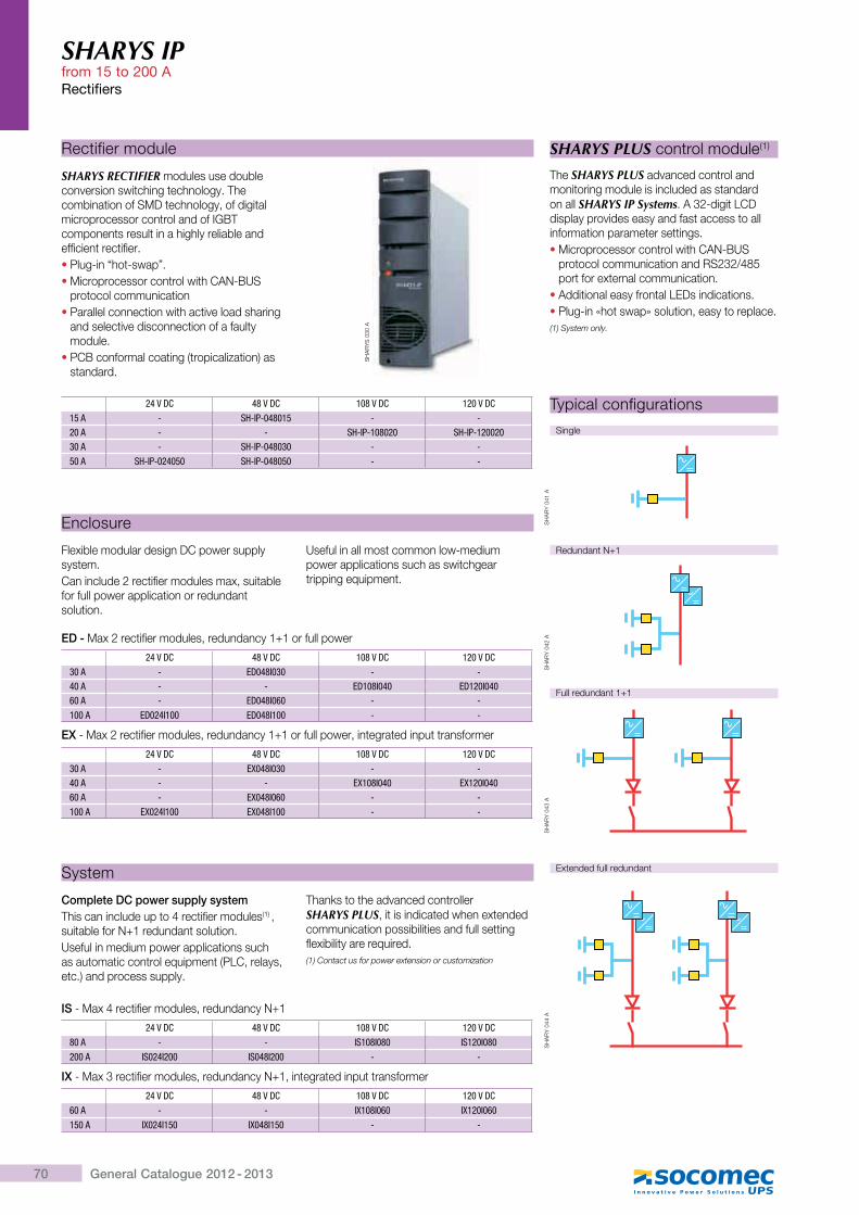
70 General Catalogue 2012 - 2013
SHARYS IP from 15 to 200 ARectifiers
Rectifier module
SHARYS RECTIFIER modules use double conversion switching technology. The combination of SMD technology, of digital microprocessor control and of IGBT components result in a highly reliable and efficient rectifier.�Plug-in “hot-swap”.�Microprocessor control with CAN-BUS
protocol communication�Parallel connection with active load sharing
and selective disconnection of a faulty module.
�PCB conformal coating (tropicalization) as standard.
SH
AR
YS
030
A
24 V DC 48 V DC 108 V DC 120 V DC15 A - SH-IP-048015 - -20 A - - SH-IP-108020 SH-IP-12002030 A - SH-IP-048030 - -50 A SH-IP-024050 SH-IP-048050 - -
ED - Max 2 rectifier modules, redundancy 1+1 or full power
24 V DC 48 V DC 108 V DC 120 V DC30 A - ED048I030 - -40 A - - ED108I040 ED120I04060 A - ED048I060 - -100 A ED024I100 ED048I100 - -
EX - Max 2 rectifier modules, redundancy 1+1 or full power, integrated input transformer
24 V DC 48 V DC 108 V DC 120 V DC30 A - EX048I030 - -40 A - - EX108I040 EX120I04060 A - EX048I060 - -100 A EX024I100 EX048I100 - -
IS - Max 4 rectifier modules, redundancy N+1
24 V DC 48 V DC 108 V DC 120 V DC80 A - - IS108I080 IS120I080200 A IS024I200 IS048I200 - -
IX - Max 3 rectifier modules, redundancy N+1, integrated input transformer
24 V DC 48 V DC 108 V DC 120 V DC60 A - - IX108I060 IX120I060150 A IX024I150 IX048I150 - -
Enclosure
Flexible modular design DC power supply system.Can include 2 rectifier modules max, suitable for full power application or redundant solution.
Useful in all most common low-medium power applications such as switchgear tripping equipment.
System
Complete DC power supply systemThis can include up to 4 rectifier modules(1) , suitable for N+1 redundant solution.Useful in medium power applications such as automatic control equipment (PLC, relays, etc.) and process supply.
Thanks to the advanced controller SHARYS PLUS, it is indicated when extended communication possibilities and full setting flexibility are required.(1) Contact us for power extension or customization
SHARYS PLUS control module(1)
The SHARYS PLUS advanced control and monitoring module is included as standard on all SHARYS IP Systems. A 32-digit LCD display provides easy and fast access to all information parameter settings.�Microprocessor control with CAN-BUS
protocol communication and RS232/485 port for external communication.
�Additional easy frontal LEDs indications.�Plug-in «hot swap» solution, easy to replace.(1) System only.
Typical configurations
Single
Redundant N+1
Full redundant 1+1
Extended full redundant
SH
AR
Y 0
41 A
SH
AR
Y 0
42 A
SH
AR
Y 0
44 A
SH
AR
Y 0
43 A
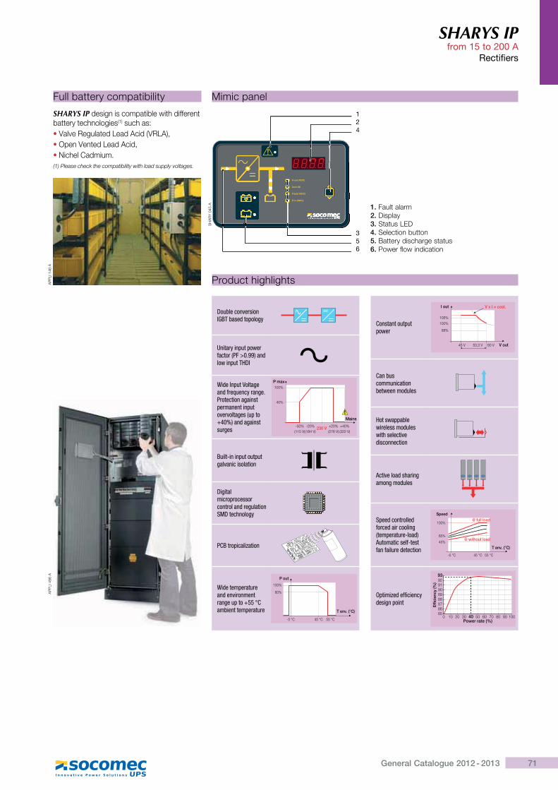
71General Catalogue 2012 - 2013
SHARYS IP from 15 to 200 A
Rectifiers
Mimic panel
1. Fault alarm 2. Display3. Status LED4. Selection button5. Battery discharge status6. Power flow indication
V out (VDC)
I out (A)
V batt (VDC)
V in (VAC)
SH
AR
Y 0
45 A
2
5
V out (VDC)
I out (A)
V batt (VDC)
6
1
4
V in (VAC)
3
AP
PLI
496
A
Product highlights
Double conversion IGBT based topology
Unitary input power Z����',$���}��;��&low input THDI
Wide Input Voltage and frequency range.Protection against permanent input overvoltages (up to +40%) and against surges
Mains
P max100%
40%
-50% -20% +20% +40%(115 V)(184 V) (276 V) (322 V)
230 V
Built-in input output galvanic isolation
Digital microprocessor control and regulationSMD technology
PCB tropicalization
Wide temperature and environment range up to +55 °C ambient temperature
P out
T env. (°C)
100%
60%
-5 °C 45 °C 55 °C
Constant output power
105%
100%
88%
45 V 53,3 V 60 V V out
V x I = cost.I out
Can bus communication between modules
Hot swappable wireless modules with selective disconnection
Active load sharing among modules
Speed controlled forced air cooling (temperature-load) Automatic self-test fan failure detection T env. (°C)
Speed@ full load
100%
45%
65%
-5 °C 45 °C 55 °C
@ without load
Optimized efficiency design point
���
����
����!
"
#�$����� ���!"0
939291908988878685
10 20 30 40 50 60 70 80 90 100
Full battery compatibility
SHARYS IP design is compatible with different battery technologies(1) such as:�Valve Regulated Lead Acid (VRLA),�Open Vented Lead Acid,�Nichel Cadmium.(1) Please check the compatibility with load supply voltages.
AP
PLI
146
A
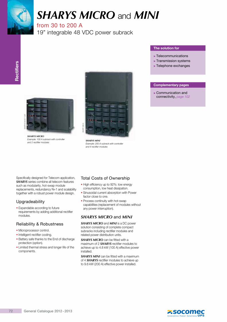
72 General Catalogue 2012 - 2013
SHARYS MICRO and MINIfrom 30 to 200 A19” integrable 48 VDC power subrack
Rec
tifie
rs
Specifically designed for Telecom application, SHARYS series combine all telecom features such as modularity, hot-swap module replacements, redundancy N+1 and scalability together with a robust power module design.
Upgradeability�Expandable according to future
requirements by adding additional rectifier modules.
Reliability & Robustness�Microprocessor control.�Intelligent rectifier cooling.�Battery safe thanks to the End of discharge
protection (option).�Limited thermal stress and longer life of the
components.
Total Costs of Ownership�High efficiency up to 92%: low energy
consumption, low heat dissipation.�Sinusoidal current absorption with Power
factor close to one.�Process continuity with hot-swap
capabilities (replacement of modules without any power interruption).
SHARYS MICRO and MINISHARYS MICRO and MINI is a DC power solution consisting of complete compact subracks including rectifier modules and related power distribution units.
SHARYS MICRO can be fitted with a ���������*�SHARYS rectifier modules to ��[��^��� �'���Q`>"##�K����� �^������installed.
SHARYS MINI can be fitted with a maximum ��'�SHARYS rectifier modules to achieve up ���!�Q`>*##�K����� �^��������� ������
SHARYS MICROExample: 100 A subrack with controller and 2 rectifier modules
SHARYS MINI Example: 200 A subrack with controller and 4 rectifier modules
~�
��
�~
##Z
|"
]�
@
~�
��
�#
!#�
The solution for
> Telecommunications> Transmission systems> Telephone exchanges
Complementary pages
> Communication and connectivity, page 102
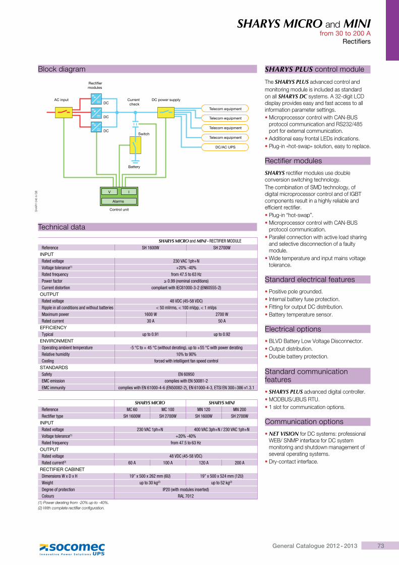
73General Catalogue 2012 - 2013
SHARYS MICRO and MINI from 30 to 200 A
Rectifiers
SHARYS PLUS control module
The SHARYS PLUS advanced control andmonitoring module is included as standard on all SHARYS DC��� �����Z*X��� {]�display provides easy and fast access to all information parameter settings.�}���������������� ����� []�_X|�~
��� ������������� �������~*Z*$'�\port for external communication.
����� ������������� ��{��������� ������Plug-in «hot-swap» solution, easy to replace.
��� ������������
SHARYS rectifier modules use double conversion switching technology. The combination of SMD technology, of digital microprocessor control and of IGBT components result in a highly reliable and efficient rectifier.�Plug-in “hot-swap”.�}���������������� ����� []�_X|�~
protocol communication.�Parallel connection with active load sharing
and selective disconnection of a faulty module.
� ��� ������ ���������� �����^�� ��tolerance.
Standard electrical features
�Positive pole grounded.�Internal battery fuse protection.�Fitting for output DC distribution.�Battery temperature sensor.
Electrical options
�BLVD Battery Low Voltage Disconnector.�Output distribution.�Double battery protection.
Standard communication features
�SHARYS PLUS advanced digital controller.�}��|�~$�|�~�@���1 slot for communication options.
Communication options
� NET VISION for DC systems: professional `�|$~_}��� ����������]��� ��monitoring and shutdown management of several operating systems.
� Dry-contact interface.
Technical data
SHARYS MICRO and MINI - RECTIFIER MODULEReference SH 1600W SH 2700W
INPUTRated voltage ������`�=�|h�����*�����'����(1) |���Q"��Rated frequency Z'��"} �������Power factor ¤��}��,����������&������;`�''���&����'���� ���=���������^{`�����Q�Q�,{h�� Q�;
OUTPUTRated voltage "j��>`," Q j�>`;@�==����������&��������&������������'��� �� ���'��z�������==z�����=���[����=���' �����_ ����_Rated current ��� ���
EFFICIENCY<\=���� �=���}�� �=���}��
ENVIRONMENT�=�'����*����������=�'���'� Q �!`��|�" �!`,�������&�'����*;z�=��| !`����=���'&�'����*@�����:�����&��\ ��������`�����* Z�'��&�����������*���Z���=��&����'��
STANDARDSSafety {h��� �{�`�������� ���=��������{h ��j�Q�{�`�������\ ���=��������{h�����Q"Q�,{h ��j�Q�;z{h�����Q"Q�z{<%^{h�����j�:�}�}�
SHARYS MICRO SHARYS MINIReference MC 60 MC 100 �h��� �h���@����Z��'�\=� SH 1600W SH 2700W SH 1600W SH 2700W
INPUTRated voltage �����`�=�|h "����`�=�|h������`�=�|h�����*�����'����(1) |���Q"��Rated frequency Z'��"} �������
OUTPUTRated voltage "j��>`," Q j�>`;Rated current(2) ��� ���� ���� ����
RECTIFIER CABINET>���������_[>[� ��§[ ��[�����,�#; ��§[ ��[ �"��,��#;_��*�� �=�����*(2) �=�� ��*(2)
>�*'���Z='�������� ^$��,������&��������'��&;`����'� @�?���
(1) Power derating from -20% up to -40%.(2) With complete rectifier configuration.
Block diagram
DC
DC
DC
V I
Alarms
Battery
AC input
Rectifier modules
Current check
DC power supply
Switch
Telecom equipment
Telecom equipment
Telecom equipment
Telecom equipment
DC/AC UPS
Control unit~�
��
�#
'#�
�|
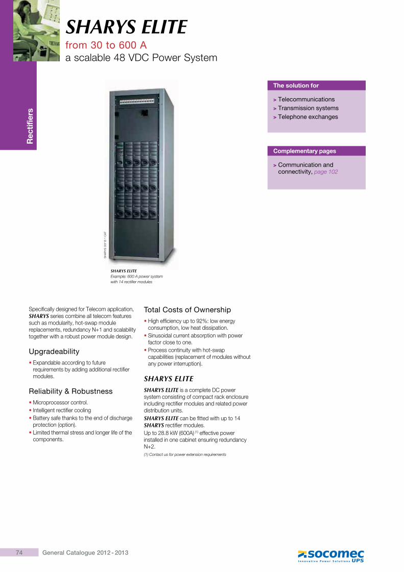
74 General Catalogue 2012 - 2013
SHARYS ELITEfrom 30 to 600 Aa scalable 48 VDC Power System
Rec
tifie
rs
The solution for
> Telecommunications> Transmission systems> Telephone exchanges
Specifically designed for Telecom application, SHARYS series combine all telecom features such as modularity, hot-swap module replacements, redundancy N+1 and scalability together with a robust power module design.
Upgradeability�Expandable according to future
requirements by adding additional rectifier modules.
Reliability & Robustness�Microprocessor control.�Intelligent rectifier cooling �Battery safe thanks to the end of discharge
protection (option).�Limited thermal stress and longer life of the
components.
Total Costs of Ownership�High efficiency up to 92%: low energy
consumption, low heat dissipation.�Sinusoidal current absorption with power
factor close to one.�Process continuity with hot-swap
capabilities (replacement of modules without any power interruption).
SHARYS ELITESHARYS ELITE is a complete DC power system consisting of compact rack enclosure including rectifier modules and related power distribution units.SHARYS ELITE can be fitted with up to 14 SHARYS rectifier modules.Up to 28.8 kW (600A) (1) effective power installed in one cabinet ensuring redundancy N+2.(1) Contact us for power extension requirements
SH
AR
YS
007
B 1
CA
T
SHARYS ELITEExample: 600 A power system with 14 rectifier modules
Complementary pages
> Communication and connectivity, page 102
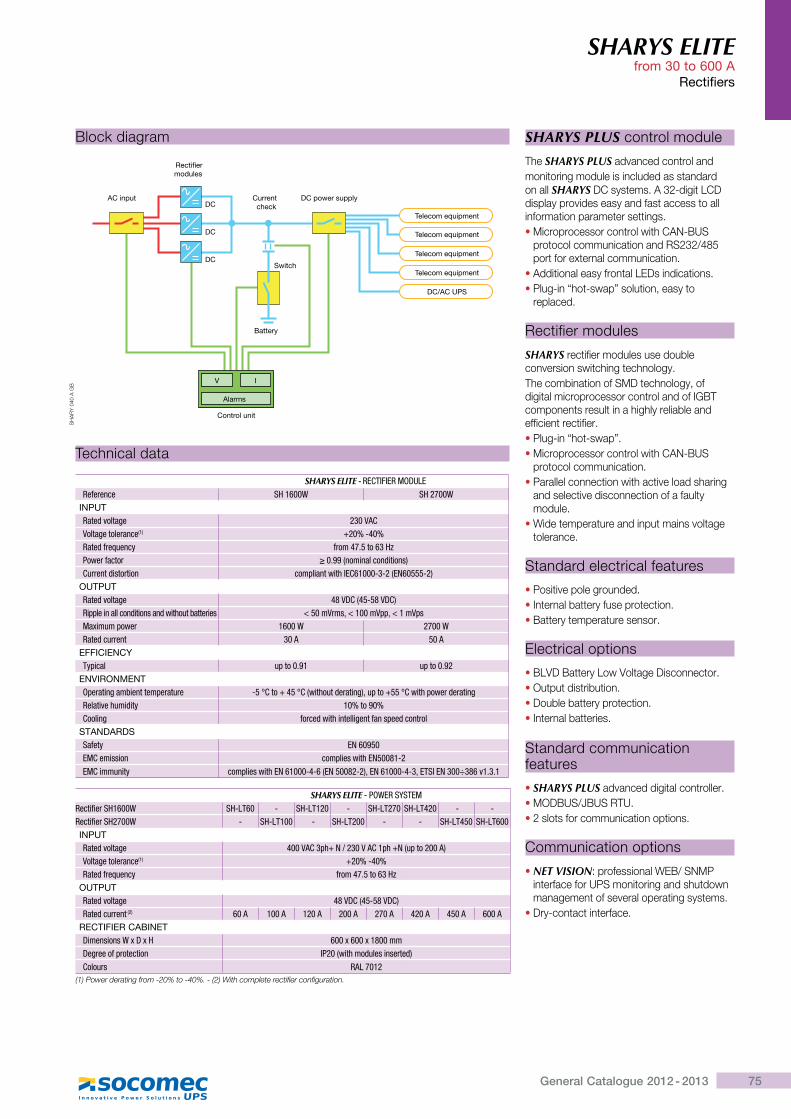
75General Catalogue 2012 - 2013
SHARYS ELITE from 30 to 600 A
Rectifiers
SHARYS PLUS control module
The SHARYS PLUS advanced control andmonitoring module is included as standard on all SHARYS DC systems. A 32-digit LCD display provides easy and fast access to all information parameter settings.�Microprocessor control with CAN-BUS
protocol communication and RS232/485 port for external communication.
�Additional easy frontal LEDs indications. �Plug-in “hot-swap” solution, easy to
replaced.
Rectifier modules
SHARYS rectifier modules use double conversion switching technology. The combination of SMD technology, of digital microprocessor control and of IGBT components result in a highly reliable and efficient rectifier.�Plug-in “hot-swap”.�Microprocessor control with CAN-BUS
protocol communication.�Parallel connection with active load sharing
and selective disconnection of a faulty module.
�Wide temperature and input mains voltage tolerance.
Standard electrical features
�Positive pole grounded.�Internal battery fuse protection.�Battery temperature sensor.
Electrical options
�BLVD Battery Low Voltage Disconnector.�Output distribution.�Double battery protection.�Internal batteries.
Standard communication features
�SHARYS PLUS advanced digital controller.�MODBUS/JBUS RTU.�2 slots for communication options.
Communication options
�NET VISION: professional WEB/ SNMP interface for UPS monitoring and shutdown management of several operating systems.
�Dry-contact interface.
SHARYS ELITE - RECTIFIER MODULEReference SH 1600W SH 2700W
INPUTRated voltage ������`�����*�����'����(1) +20% -40%Rated frequency Z'��"} �������Power factor ¤��}��,����������&������;`�''���&����'���� ���=���������^{`�����Q�Q�,{h�� Q�;
OUTPUTRated voltage "j��>`," Q j�>`;@�==����������&��������&������������'��� �� ���'��z�������==z�����=���[����=���' �����_ ����_Rated current ��� ���
EFFICIENCY<\=���� �=���}�� �=���}��
ENVIRONMENT�=�'����*����������=�'���'� Q �!`��|�" �!`,�������&�'����*;z�=��| !`����=���'&�'����*@�����:�����&��\ ��������`�����* Z�'��&�����������*���Z���=��&����'��
STANDARDSSafety {h��� �{�`�������� ���=��������{h ��j�Q�{�`�������\ ���=��������{h�����Q"Q�,{h ��j�Q�;z{h�����Q"Q�z{<%^{h�����j�:�}�}�
Technical data
SHARYS ELITE - POWER SYSTEM@����Z��'%�����_ SH-LT60 - SH-LT120 - SH-LT270 SH-LT420 - -@����Z��'%����_ - SH-LT100 - SH-LT200 - - SH-LT450 SH-LT600INPUTRated voltage "����`�=�|�h������`�=�|h,�=������;�����*�����'����(1) +20% -40%Rated frequency Z'��"} �������
OUTPUTRated voltage "j��>`," Q j�>`;Rated current (2) ��� ���� ���� ���� ��� "��� " �� ����
RECTIFIER CABINET>���������_[>[� 600 x 600 x 1800 mm>�*'���Z='�������� ^$��,������&��������'��&;`����'� @�?���
(1) Power derating from -20% to -40%. - (2) With complete rectifier configuration.
Block diagram
DC
DC
DC
V I
Alarms
Battery
AC input
Rectifier modules
Current check
DC power supply
Switch
Telecom equipment
Telecom equipment
Telecom equipment
Telecom equipment
DC/AC UPS
Control unit
SH
AR
Y 0
40 A
GB
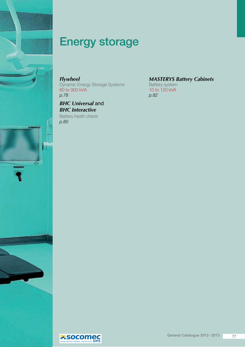
77General Catalogue 2012 - 2013
Energy storage
Flywheel Dynamic Energy Storage Systems 60 to 900 kVA p.78
BHC Universal and BHC InteractiveBattery heath checkp.80
MASTERYS Battery Cabinets Battery system 10 to 120 kVA p.82
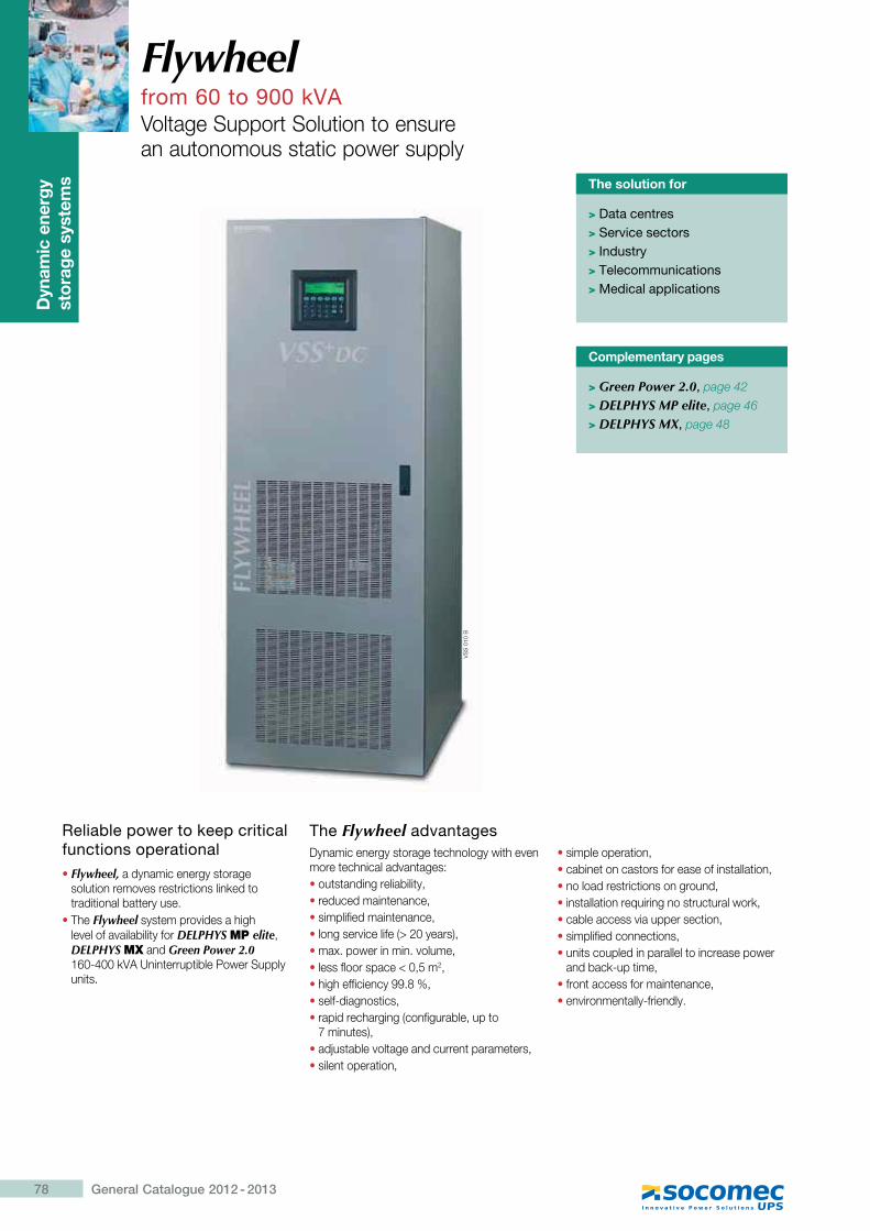
78 General Catalogue 2012 - 2013
Flywheelfrom 60 to 900 kVAVoltage Support Solution to ensure an autonomous static power supply
Dyn
amic
ene
rgy
stor
age
syst
ems The solution for
> Data centres> Service sectors> Industry> Telecommunications> Medical applications
Reliable power to keep critical functions operational�Flywheel, a dynamic energy storage
solution removes restrictions linked to traditional battery use.
�The Flywheel system provides a high level of availability for DELPHYS MP elite, DELPHYS MX and Green Power 2.0 160-400 kVA Uninterruptible Power Supply units.
The Flywheel advantagesDynamic energy storage technology with even more technical advantages:�outstanding reliability,�reduced maintenance,�simplified maintenance,�long service life (> 20 years),�max. power in min. volume,�less floor space < 0,5 m2,�high efficiency 99.8 %,�self-diagnostics,�rapid recharging (configurable, up to
������ ��K��adjustable voltage and current parameters,�silent operation,
�simple operation,�cabinet on castors for ease of installation,�no load restrictions on ground,�installation requiring no structural work,�cable access via upper section,�simplified connections,�units coupled in parallel to increase power
and back-up time,�front access for maintenance,�environmentally-friendly.
VS
S 0
10 B
Complementary pages
> Green Power 2.0, page 42
> DELPHYS MP elite, page 46
> DELPHYS MX, page 48
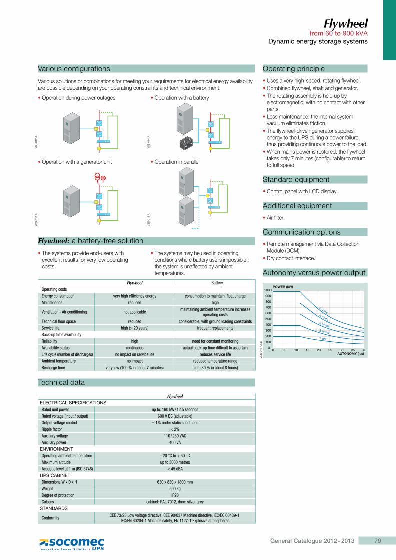
79General Catalogue 2012 - 2013
Flywheel from 60 to 900 kVA
Dynamic energy storage systems
Various configurations
Various solutions or combinations for meeting your requirements for electrical energy availability are possible depending on your operating constraints and technical environment.
Flywheel: a battery-free solution
Technical data
FlywheelELECTRICAL SPECIFICATIONSRated unit power �=��������_���} �����&�@���&:����*�,^�=������=��; ����>`,�&¨�������;���=��:����*�����'�� �����&�'���������&������@�==��Z����' ����Auxiliary voltage ���������`Auxiliary power 400 VA
ENVIRONMENT�=�'����*����������=�'���'� Q���!`��|� ��!`Maximum altitude �=���������'������������:������,^%��"�; ��" �&]�
UPS CABINET>���������_[>[� ���[j��[�j����_��*�� ���*>�*'���Z='�������� ^$��`����'� ��������@�?���z&��'����:�'*'�\
STANDARDS
Conformity `{{����?��:����*�&�'����:�z`{{�j����������&�'����:�z^{`�{`��"��Q�z^{`�{h����"Q����������Z��\z{h���Q�{[=����:������=��'��
Operating principle
�Uses a very high-speed, rotating flywheel.�Combined flywheel, shaft and generator.�The rotating assembly is held up by
electromagnetic, with no contact with other parts.
�Less maintenance: the internal system vacuum eliminates friction.
�The flywheel-driven generator supplies energy to the UPS during a power failure, thus providing continuous power to the load.
�When mains power is restored, the flywheel takes only 7 minutes (configurable) to return to full speed.
Standard equipment
�Control panel with LCD display.
Additional equipment
�Air filter.
Communication options
�Remote management via Data Collection Module (DCM).
�Dry contact interface.
Autonomy versus power output
�Operation during power outages
�Operation with a generator unit
�Operation with a battery
�Operation in parallel
00
100
200
300
400
500
600
700
800
900
1000
5 10 15 20 25 30 35 40AUTONOMY (ies)
1 unit
2 units
3 units
4 units
5 units
POWER (kW)
VS
S 0
16 A
GB
�The systems provide end-users with excellent results for very low operating costs.
�The systems may be used in operating ����� �����[����� ��������������������the system is unaffected by ambient temperatures.
Flywheel ]����'\�=�'����*�����{��'*\������=���� :�'\��*��ZZ������\���'*\ ������=��������������zZ�������'*������������ '�&���& ��*�
�����������Q��'���&�������* ����==������� ����������*����������=�'���'����'������=�'����*�����
<��������Z���'�=��� '�&���& �����&�'����z����*'���&���&��*�����'�����%�':�����Z� ��*�,���\��'�; Z'������'�=���������]���Q�=�����:���������\@���������\ ��*� ���&Z�'��������������'��*�:���������\������ ���������� ����������Q�=����&�ZZ�����������'����?�Z��\���,�����'�Z&�����'*��; ����=�������':�����Z� '�&������':�����Z�����������=�'���'� ����=��� '�&���&���=�'���'�'��*�@����'*����� :�'\���,������������������; ��*�,j���������j���'�;
VS
S 0
12 A
��
VS
S 0
13 A
VS
S 0
14 A
VS
S 0
15 A
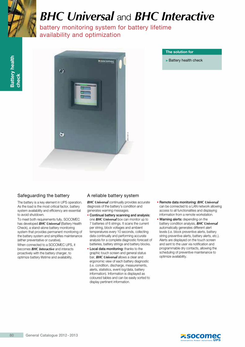
Thr
ee-p
hase
UP
S
syst
em
80 General Catalogue 2012 - 2013
BHC Universal and BHC Interactivebattery monitoring system for battery lifetime availability and optimization
Bat
tery
hea
lth
chec
k
The solution for
> Battery health check
Safeguarding the battery The battery is a key element in UPS operation. As the load is the most critical factor, battery system availability and efficiency are essential to avoid shutdown.To meet both requirements fully, SOCOMEC has developed BHC Universal (Battery Health Check), a stand-alone battery monitoring system that provides permanent monitoring of the battery system and simplifies maintenance (either preventative or curative).When connected to a SOCOMEC UPS, it becomes BHC Interactive and interacts proactively with the battery charger, to optimize battery lifetime and availability.
BH
C 0
01 A
BHC Universal continually provides accurate diagnosis of the battery’s condition and generates warning messages.�Continual battery scanning and analysis:
one BHC Universal box can monitor up to 7 batteries of 6 strings. It scans the current per string, block voltages and ambient temperatures every 10 seconds, collecting data continually and performing accurate analysis for a complete diagnostic forecast of batteries, battery strings and battery blocks.
�Local data monitoring: thanks to the graphic touch screen and general status bar, BHC Universal allows a clear and ergonomic view of each battery diagnostic (i.e. condition, discharge, measurements, alerts, statistics, event log/data, battery information). Information is displayed as coloured tables and can be easily sorted to display pertinent information.
�Remote data monitoring: BHC Universal can be connected to a LAN network allowing access to all functionalities and displaying information from a remote workstation.
�Warning alerts: depending on the battery condition analysis, BHC Universal automatically generates different alert levels (i.e. block preventive alerts, battery string preventive alerts, battery alerts, etc.). Alerts are displayed on the touch screen and sent to the user via notification and programmable dry contacts, allowing the scheduling of preventive maintenance to optimize availability.
A reliable battery system
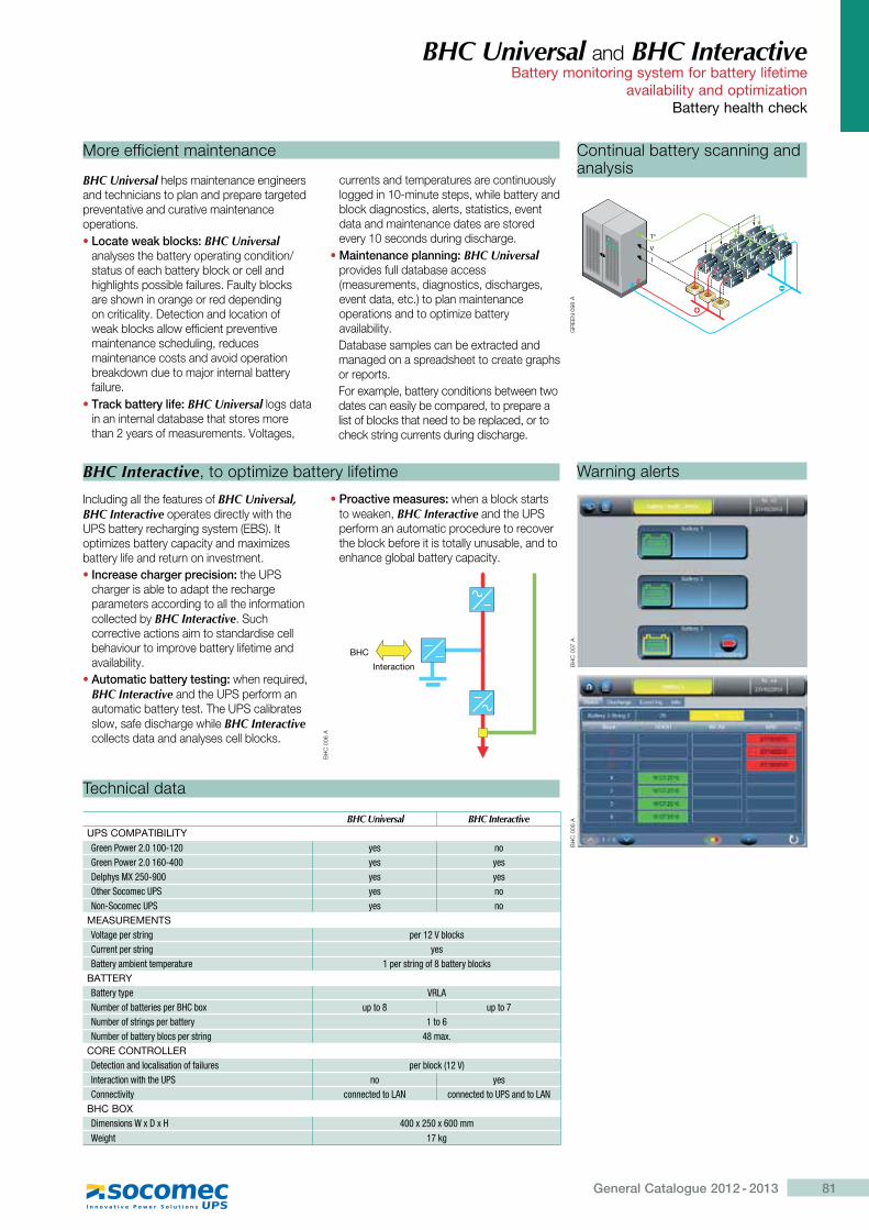
81General Catalogue 2012 - 2013
BHC Universal and BHC Interactive Battery monitoring system for battery lifetime
availability and optimizationBattery health check
More efficient maintenance
BHC Universal helps maintenance engineers and technicians to plan and prepare targeted preventative and curative maintenance operations.�Locate weak blocks: BHC Universal
analyses the battery operating condition/status of each battery block or cell and highlights possible failures. Faulty blocks are shown in orange or red depending on criticality. Detection and location of weak blocks allow efficient preventive maintenance scheduling, reduces maintenance costs and avoid operation breakdown due to major internal battery failure.
�Track battery life: BHC Universal logs data in an internal database that stores more than 2 years of measurements. Voltages,
currents and temperatures are continuously logged in 10-minute steps, while battery and block diagnostics, alerts, statistics, event data and maintenance dates are stored every 10 seconds during discharge.
�Maintenance planning: BHC Universal provides full database access (measurements, diagnostics, discharges, event data, etc.) to plan maintenance operations and to optimize battery availability.Database samples can be extracted and managed on a spreadsheet to create graphs or reports.For example, battery conditions between two dates can easily be compared, to prepare a list of blocks that need to be replaced, or to check string currents during discharge.
BHC Interactive, to optimize battery lifetime
Including all the features of BHC Universal, BHC Interactive operates directly with the UPS battery recharging system (EBS). It optimizes battery capacity and maximizes battery life and return on investment.� Increase charger precision: the UPS
charger is able to adapt the recharge parameters according to all the information collected by BHC Interactive. Such corrective actions aim to standardise cell behaviour to improve battery lifetime and availability.
�Automatic battery testing: when required, BHC Interactive and the UPS perform an automatic battery test. The UPS calibrates slow, safe discharge while BHC Interactive collects data and analyses cell blocks.
�Proactive measures: when a block starts to weaken, BHC Interactive and the UPS perform an automatic procedure to recover the block before it is totally unusable, and to enhance global battery capacity.
Technical data
BHC Universal BHC InteractiveUPS COMPATIBILITYGreen Power 2.0 100-120 yes noGreen Power 2.0 160-400 yes yesDelphys MX 250-900 yes yesOther Socomec UPS yes noNon-Socomec UPS yes no
MEASUREMENTSVoltage per string per 12 V blocksCurrent per string yesBattery ambient temperature 1 per string of 8 battery blocks
BATTERYBattery type VRLA Number of batteries per BHC box up to 8 up to 7Number of strings per battery 1 to 6Number of battery blocs per string 48 max.
CORE CONTROLLERDetection and localisation of failures per block (12 V)Interaction with the UPS no yesConnectivity connected to LAN connected to UPS and to LAN
BHC BOXDimensions W x D x H 400 x 250 x 600 mmWeight 17 kg
Continual battery scanning and analysis
BH
C 0
06 A
Warning alerts
GR
EE
N 0
98 A
���DELPHYS Green Power �
�
��
BH
C 0
07 A
Interaction
BHC
BH
C 0
06 A
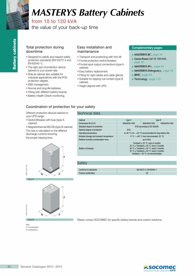
Bat
tery
cab
inet
s
82 General Catalogue 2012 - 2013
Bat
tery
cab
inet
s
Total protection during downtime� Designed to satisfy and respect safety
protection standards (EN 50272-2 and EN 62040-1).
� The right size of protection device tailored to your power rate.
� Robust cabinet also suitable for industrial applications with the IP32 protection degree.
� EBS management.� Normal and long-life batteries.� Fitting with different battery brands.� Battery Health Check monitoring.
Easy installation and maintenance� Transport and positioning with fork-lift.� Frontal protection switch/breaker.� Frontal input output connections (type A
cabinet).� Easy battery replacement.� Fitting for rigid cables and cable-glands.� Suitable for tripping coil contact (type B
cabinet).� Height aligned with UPS.
MASTERYS Battery Cabinetsfrom 10 to 120 kVAthe value of your back-up time
Complementary pages
> MASTERYS BC, page 34
> Green Power 2.0 10-120 kVA, page 40
> MASTERYS IP+, page 44
> MASTERYS EMergency, page 54
> BHC, page 80
> Technology, page 110
Different protection devices tailored to your UPS range:� Switch/Breaker with fuse (type A
cabinet)� Magnetothermal MCCB (type B cabinet)The size is calculated on the different discharge currents ensuringthe proper tripping time.
Cabinet type A type BDimensions W x D x H 600x835x1400 800x845x1930 1000x845x1930Standard degree of protection IP20 (according to IEC 60529)Optional degree of protection IP32 - -Operating temperature 0÷40 °C (15÷ +25 °C recommended for long battery life)Ambient storage and transport temperature -5 °C ÷ +40 °C max (reccomended: 25 °C)Relative humidity (condensation-free) up to 95%
Battery recharging
<��������� !`��:�'\�������� !`�<����������!`��:�'\"��������!`�<��������� !`��:�'\�������� !`�<��������"�!`��:�'\�������
Tambient > 40 °C: not recommended
Please contact SOCOMEC for specific battery brands and custom solutions.
Technical data
Conforms to standards EN 50272-2, EN 62040-1
Product certification CE
Safety
Coordination of protection for your safety
Key:C: connections P: protections
H
DW
PPP
CCC
H
DW
PPP
CCC
Type A
Type B
MA
STE
058
A G
BM
AS
TE 0
59 A
GB
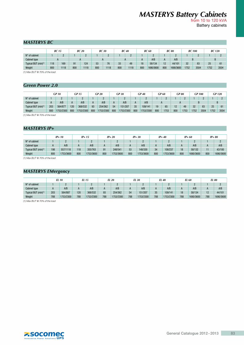
83General Catalogue 2012 - 2013
MASTERYS Battery Cabinetsfrom 10 to 120 kVA
Battery cabinets
MASTERYS BC
BC 15 BC 20 BC 30 BC 40 BC 60 BC 80 BC 100 BC 120
N° of cabinet 1 2 1 2 1 2 1 2 1 2 1 2 1 2 1 2Cabinet type A A A A A A/B A A/B B BTypical BUT (min)(1) 118 169 91 124 53 76 33 49 18 58/134 12 44/101 32 83 25 61Weight 800 1118 800 1118 800 1118 800 1118 800 1690/3600 800 1690/3600 1752 3504 1752 3504
(1) Max BUT @ 70% of the load
Green Power 2.0
GP 10 GP 15 GP 20 GP 30 GP 40 GP 60 GP 80 GP 100 GP 120
N° of cabinet 1 2 1 2 1 2 1 2 1 2 1 2 1 2 1 2 1 2Cabinet type A A/B A A/B A A/B A A/B A A/B A A B BTypical BUT (min)(1) 203 564/877 120 368/532 93 254/362 54 151/207 35 109/141 19 65 12 49 32 83 25 61Weight 800 1753/2300 800 1753/2300 800 1753/2300 800 1753/2300 800 1753/2300 800 1753 800 1753 1752 3504 1752 3504
(1) Max BUT @ 70% of the load
MASTERYS IP+
IP+ 10 IP+ 15 IP+ 20 IP+ 30 IP+ 40 IP+ 60 IP+ 80
N° of cabinet 1 2 1 2 1 2 1 2 1 2 1 2 1 2Cabinet type A A/B A A/B A A/B A A/B A A/B A A/B A A/BTypical BUT (min)(1) 198 557/1118 118 355/763 91 248/541 53 148/330 34 108/237 18 58/132 11 43/100Weight 800 1753/3600 800 1753/3600 800 1753/3600 800 1753/3600 800 1753/3600 800 1690/3600 800 1690/3600
(1) Max BUT @ 70% of the load
MASTERYS EMergency
EL 10 EL 15 EL 20 EL 30 EL 40 EL 60 EL 80
N° of cabinet 1 2 1 2 1 2 1 2 1 2 1 2 1 2Cabinet type A A/B A A/B A A/B A A/B A A/B A A/B A A/BTypical BUT (min)(1) 203 564/887 120 368/532 93 254/362 54 151/207 35 109/141 18 58/134 12 44/101Weight 788 1753/2300 788 1753/2300 788 1753/2300 788 1753/2300 788 1753/2300 788 1690/3600 788 1690/3600
(1) Max BUT @ 70% of the load
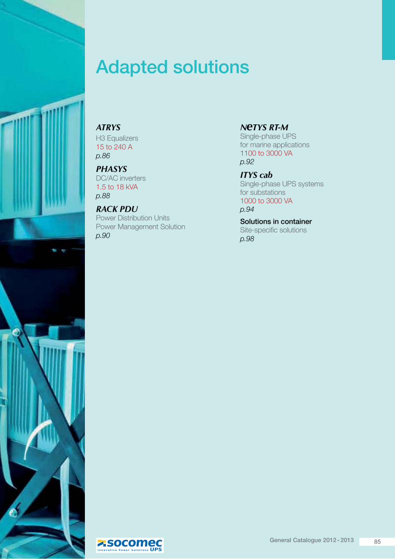
85General Catalogue 2012 - 2013
Adapted solutions
ATRYSH3 Equalizers15 to 240 Ap.86
PHASYS DC/AC inverters1.5 to 18 kVAp.88
RACK PDU Power Distribution Units Power Management Solutionp.90
N TYS RT-M Single-phase UPS for marine applications 1100 to 3000 VA p.92
ITYS cab Single-phase UPS systems for substations 1000 to 3000 VA p.94
Solutions in container ~� �X����������� ����p.98
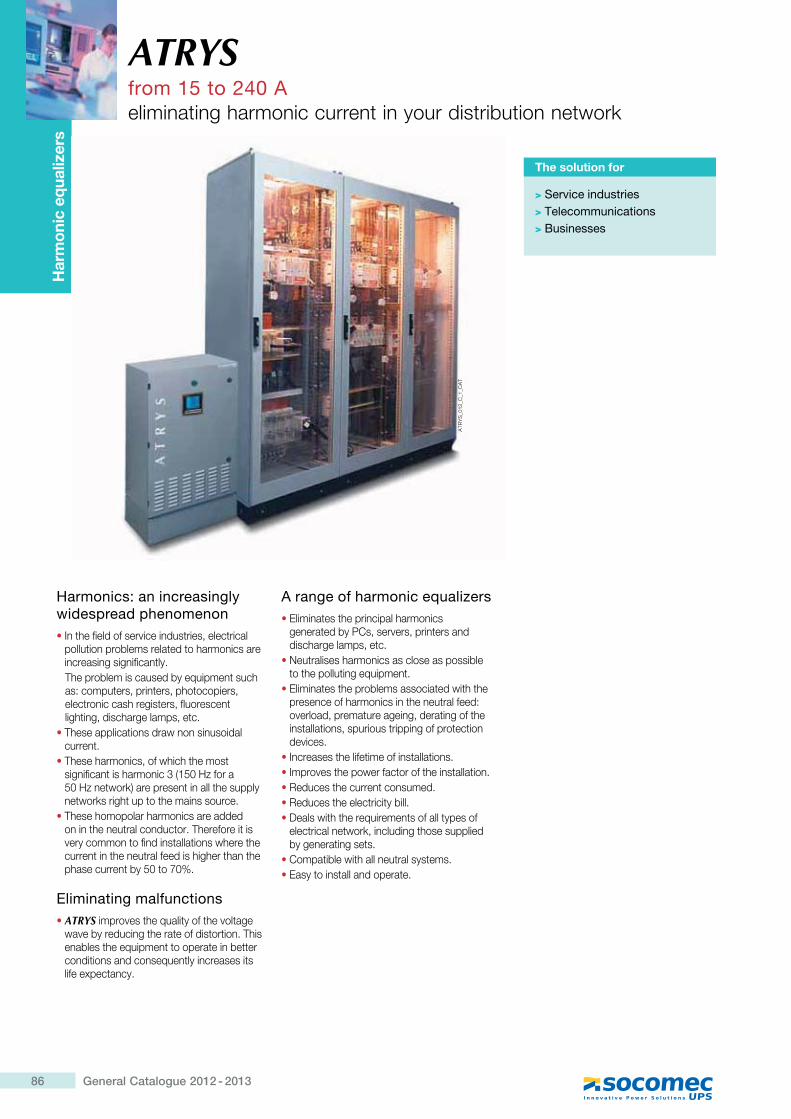
86 General Catalogue 2012 - 2013
ATRYSfrom 15 to 240 Aeliminating harmonic current in your distribution network
Har
mon
ic e
qual
izer
s
Harmonics: an increasingly widespread phenomenon� In the field of service industries, electrical
pollution problems related to harmonics are increasing significantly.The problem is caused by equipment such as: computers, printers, photocopiers, electronic cash registers, fluorescent lighting, discharge lamps, etc.
� These applications draw non sinusoidal current.
� These harmonics, of which the most ��������� ��[�������Z>"\#�������\#����� ���QK��������� ����� [�������networks right up to the mains source.
� These homopolar harmonics are added on in the neutral conductor. Therefore it is very common to find installations where the current in the neutral feed is higher than the phase current by 50 to 70%.
Eliminating malfunctions� ATRYS improves the quality of the voltage
wave by reducing the rate of distortion. This enables the equipment to operate in better conditions and consequently increases its life expectancy.
A range of harmonic equalizers� Eliminates the principal harmonics
generated by PCs, servers, printers and discharge lamps, etc.
� Neutralises harmonics as close as possible to the polluting equipment.
� Eliminates the problems associated with the presence of harmonics in the neutral feed: overload, premature ageing, derating of the installations, spurious tripping of protection devices.
� Increases the lifetime of installations. � Improves the power factor of the installation.� Reduces the current consumed.� Reduces the electricity bill.� Deals with the requirements of all types of
electrical network, including those supplied by generating sets.
� Compatible with all neutral systems.� Easy to install and operate.
The solution for
> Service industries> Telecommunications> Businesses
ATR
YS
_012
_C_1
_CA
T
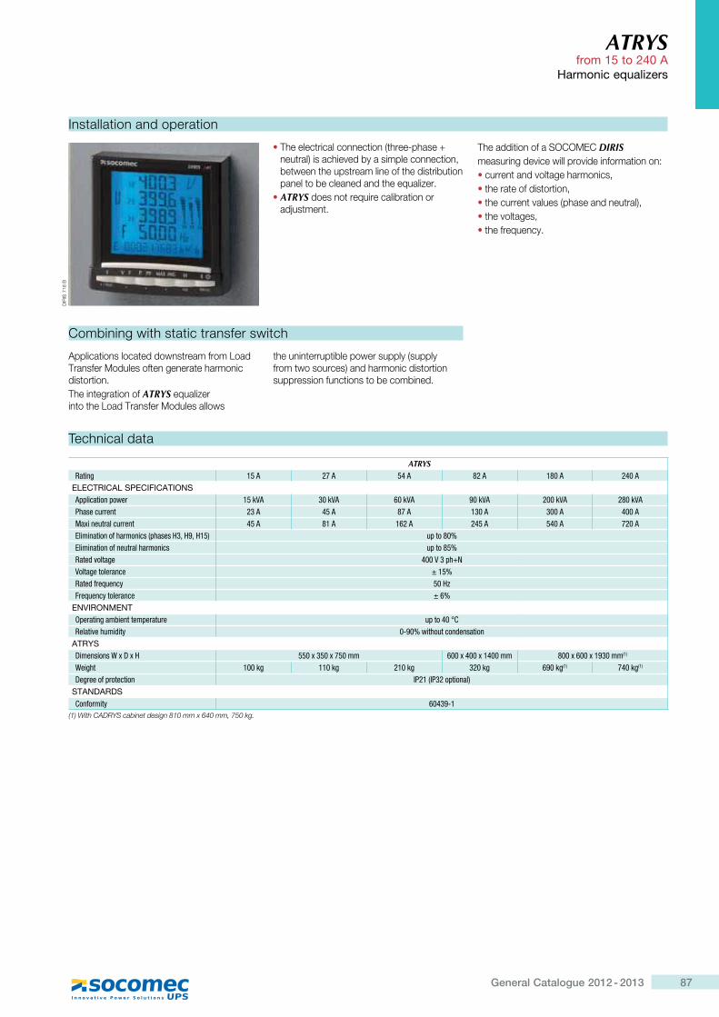
87General Catalogue 2012 - 2013
ATRYS from 15 to 240 A
Harmonic equalizers
Technical data
ATRYSRating 15 A 27 A 54 A 82 A 180 A 240 A
ELECTRICAL SPECIFICATIONSApplication power 15 kVA 30 kVA 60 kVA 90 kVA 200 kVA 280 kVAPhase current 23 A 45 A 87 A 130 A 300 A 400 AMaxi neutral current 45 A 81 A 162 A 245 A 540 A 720 AElimination of harmonics (phases H3, H9, H15) up to 80%Elimination of neutral harmonics up to 85%Rated voltage 400 V 3 ph+NVoltage tolerance ± 15%Rated frequency ����Frequency tolerance ± 6%
ENVIRONMENTOperating ambient temperature �=��"��!`Relative humidity 0-90% without condensation
ATRYSDimensions W x D x H 550 x 350 x 750 mm 600 x 400 x 1400 mm 800 x 600 x 1930 mm(1)
Weight 100 kg 110 kg 210 kg 320 kg 690 kg(1) 740 kg(1)
Degree of protection IP21 (IP32 optional)STANDARDS`��Z�'���\ 60439-1
����[��#��� ��}���������Y���"����N����{�|_N���;��N��"�
Installation and operation
Combining with static transfer switch
DIR
IS 7
18 B
� The electrical connection (three-phase + ��� ���K����[��^����������������� ����between the upstream line of the distribution ����� ������������� [�����������
� ATRYS does not require calibration or adjustment.
The addition of a SOCOMEC DIRISmeasuring device will provide information on:� current and voltage harmonics,� the rate of distortion,� [������� ^�����>�[��������� ���K�� the voltages,� the frequency.
Applications located downstream from Load Transfer Modules often generate harmonic distortion.The integration of ATRYS���������into the Load Transfer Modules allows
[������ ����� ���������������>���������� ���������K���[���������� �� ���suppression functions to be combined.
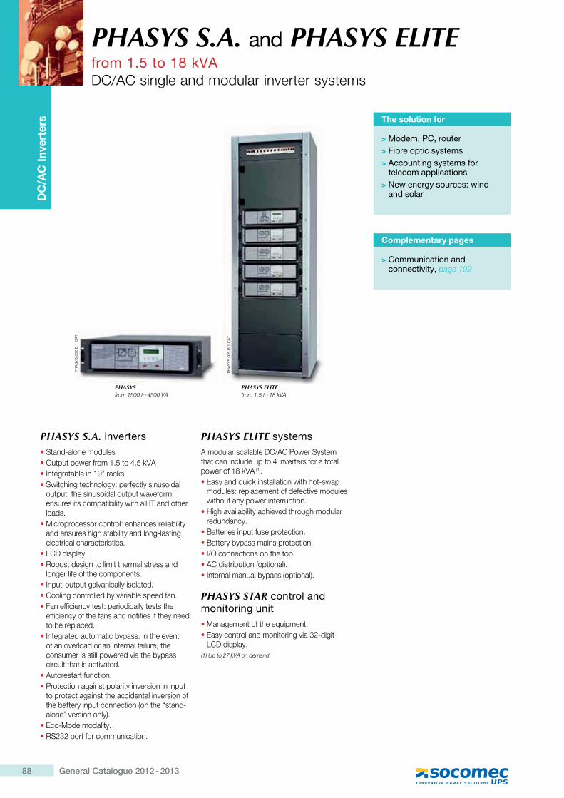
88 General Catalogue 2012 - 2013
PHASYS S.A. and PHASYS ELITEfrom 1.5 to 18 kVADC/AC single and modular inverter systems
DC
/AC
Inve
rter
s The solution for
> Modem, PC, router> Fibre optic systems> Accounting systems for
telecom applications> New energy sources: wind
and solar
PHASYS S.A. inverters�Stand-alone modules�Output power from 1.5 to 4.5 kVA�Integratable in 19” racks.�Switching technology: perfectly sinusoidal
output, the sinusoidal output waveform ensures its compatibility with all IT and other loads.
�Microprocessor control: enhances reliability and ensures high stability and long-lasting electrical characteristics.
�LCD display.�Robust design to limit thermal stress and
longer life of the components.�Input-output galvanically isolated.�Cooling controlled by variable speed fan.�Fan efficiency test: periodically tests the
efficiency of the fans and notifies if they need to be replaced.
�Integrated automatic bypass: in the event of an overload or an internal failure, the consumer is still powered via the bypass circuit that is activated.
�Autorestart function.�Protection against polarity inversion in input
to protect against the accidental inversion of the battery input connection (on the “stand-alone” version only).
�Eco-Mode modality.�RS232 port for communication.
PHASYS ELITE systemsA modular scalable DC/AC Power System that can include up to 4 inverters for a total power of 18 kVA (1).�Easy and quick installation with hot-swap
modules: replacement of defective modules without any power interruption.
�High availability achieved through modular redundancy.
�Batteries input fuse protection.�Battery bypass mains protection.�I/O connections on the top.�AC distribution (optional).�Internal manual bypass (optional).
PHASYS STAR control and monitoring unit�Management of the equipment.�Easy control and monitoring via 32-digit
LCD display.(1) Up to 27 kVA on demand
PH
AS
YS
002
B 1
CA
T
PH
AS
YS
005
B 1
CA
T
Complementary pages
> Communication and connectivity, page 102
PHASYS ELITE from 1.5 to 18 kVA
PHASYS from 1500 to 4500 VA
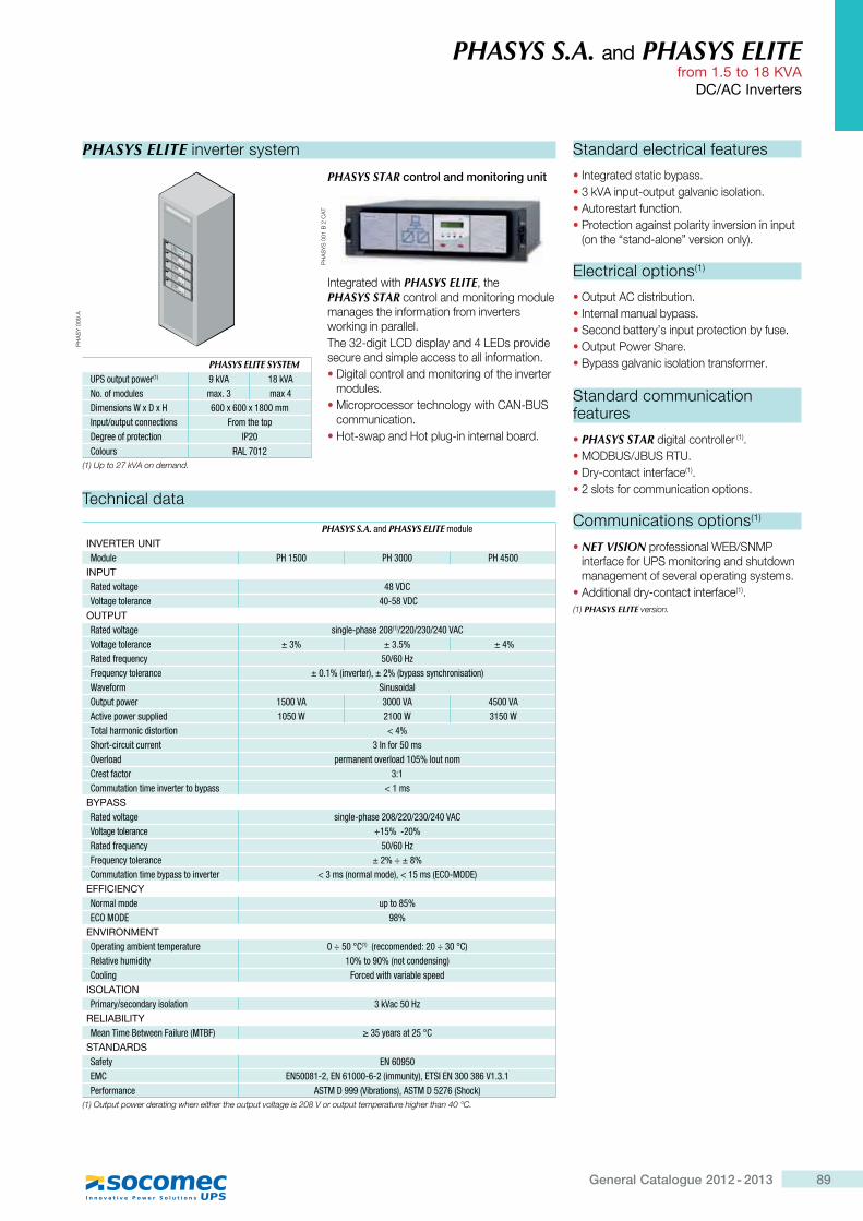
89General Catalogue 2012 - 2013
PHASYS S.A. and PHASYS ELITE from 1.5 to 18 KVA
DC/AC Inverters
Standard electrical features
�Integrated static bypass.�3 kVA input-output galvanic isolation.�Autorestart function.�Protection against polarity inversion in input
(on the “stand-alone” version only).
Electrical options(1)
�Output AC distribution.�Internal manual bypass.�Second battery’s input protection by fuse.�Output Power Share.�Bypass galvanic isolation transformer.
Standard communication features
�PHASYS STAR digital controller (1).�MODBUS/JBUS RTU. �Dry-contact interface(1). �2 slots for communication options.
Communications options(1)
�NET VISION professional WEB/SNMP interface for UPS monitoring and shutdown management of several operating systems.
�Additional dry-contact interface(1). (1) PHASYS ELITE version.
PHASYS S.A. and PHASYS ELITE moduleINVERTER UNITModule PH 1500 PH 3000 PH 4500
INPUTRated voltage 48 VDCVoltage tolerance 40-58 VDC
OUTPUTRated voltage single-phase 208(1)/220/230/240 VACVoltage tolerance ± 3% ± 3.5% ± 4%Rated frequency �������Frequency tolerance ± 0.1% (inverter), ± 2% (bypass synchronisation)Waveform SinusoidalOutput power 1500 VA 3000 VA 4500 VAActive power supplied 1050 W 2100 W 3150 WTotal harmonic distortion < 4%Short-circuit current 3 In for 50 msOverload permanent overload 105% Iout nomCrest factor 3:1Commutation time inverter to bypass < 1 ms
BYPASSRated voltage single-phase 208/220/230/240 VACVoltage tolerance +15% -20%Rated frequency ������Frequency tolerance ± 2% ÷ ± 8%Commutation time bypass to inverter < 3 ms (normal mode), < 15 ms (ECO-MODE)
EFFICIENCYNormal mode up to 85%ECO MODE 98%
ENVIRONMENTOperating ambient temperature 0 ÷ 50 °C(1) (reccomended: 20 ÷ 30 °C)Relative humidity 10% to 90% (not condensing)Cooling Forced with variable speed
ISOLATIONPrimary/secondary isolation ����� ���
RELIABILITYMean Time Between Failure (MTBF) ¤� \��'���� !`
STANDARDSSafety EN 60950EMC EN50081-2, EN 61000-6-2 (immunity), ETSI EN 300 386 V1.3.1 Performance ASTM D 999 (Vibrations), ASTM D 5276 (Shock)
(1) Output power derating when either the output voltage is 208 V or output temperature higher than 40 °C.
Technical data
PHASYS ELITE inverter system
PHASYS STAR control and monitoring unit
Integrated with PHASYS ELITE, the PHASYS STAR control and monitoring module manages the information from inverters working in parallel.The 32-digit LCD display and 4 LEDs provide secure and simple access to all information.�Digital control and monitoring of the inverter
modules.�Microprocessor technology with CAN-BUS
communication.�Hot-swap and Hot plug-in internal board.
PH
AS
Y 0
09 A
PH
AS
YS
001
B 2
CA
T
PHASYS ELITE SYSTEMUPS output power(1) 9 kVA 18 kVANo. of modules max. 3 max 4Dimensions W x D x H 600 x 600 x 1800 mmInput/output connections From the topDegree of protection IP20Colours RAL 7012
(1) Up to 27 kVA on demand.
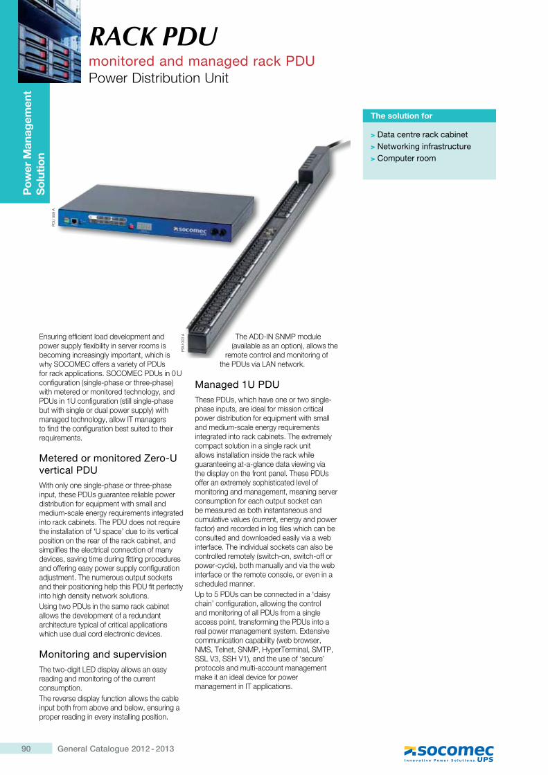
90 General Catalogue 2012 - 2013
RACK PDUmonitored and managed rack PDUPower Distribution Unit
Pow
er M
anag
emen
t S
olut
ion
Ensuring efficient load development and power supply flexibility in server rooms is becoming increasingly important, which is why SOCOMEC offers a variety of PDUs for rack applications. SOCOMEC PDUs in 0 U configuration (single-phase or three-phase) with metered or monitored technology, and PDUs in 1U configuration (still single-phase but with single or dual power supply) with managed technology, allow IT managers to find the configuration best suited to their requirements.
Metered or monitored Zero-U vertical PDUWith only one single-phase or three-phase input, these PDUs guarantee reliable power distribution for equipment with small and medium-scale energy requirements integrated into rack cabinets. The PDU does not require the installation of ‘U space’ due to its vertical position on the rear of the rack cabinet, and simplifies the electrical connection of many devices, saving time during fitting procedures and offering easy power supply configuration adjustment. The numerous output sockets and their positioning help this PDU fit perfectly into high density network solutions.Using two PDUs in the same rack cabinet allows the development of a redundant architecture typical of critical applications which use dual cord electronic devices.
Monitoring and supervisionThe two-digit LED display allows an easy reading and monitoring of the current consumption.The reverse display function allows the cable input both from above and below, ensuring a proper reading in every installing position.
The ADD-IN SNMP module (available as an option), allows the
remote control and monitoring of the PDUs via LAN network.
Managed 1U PDUThese PDUs, which have one or two single-phase inputs, are ideal for mission critical power distribution for equipment with small and medium-scale energy requirements integrated into rack cabinets. The extremely compact solution in a single rack unit allows installation inside the rack while guaranteeing at-a-glance data viewing via the display on the front panel. These PDUs offer an extremely sophisticated level of monitoring and management, meaning server consumption for each output socket can be measured as both instantaneous and cumulative values (current, energy and power factor) and recorded in log files which can be consulted and downloaded easily via a web interface. The individual sockets can also be controlled remotely (switch-on, switch-off or power-cycle), both manually and via the web interface or the remote console, or even in a scheduled manner.Up to 5 PDUs can be connected in a ‘daisy chain’ configuration, allowing the control and monitoring of all PDUs from a single access point, transforming the PDUs into a real power management system. Extensive communication capability (web browser, NMS, Telnet, SNMP, HyperTerminal, SMTP, SSL V3, SSH V1), and the use of ‘secure’ protocols and multi-account management make it an ideal device for power management in IT applications.
The solution for
> Data centre rack cabinet> Networking infrastructure> Computer room
PD
U 0
09 A
The ADD-IN SNMP module (available as an option), allows the
remote control and monitoring of
PD
U 0
03 A
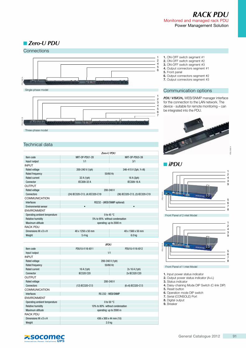
91General Catalogue 2012
RACK PDU Monitored and managed rack PDU
Power Management Solution
Communication options
PDU VISION, WEB/SNMP manager interface for the connection to the LAN network. The device - suitable for remote monitoring – can be integrated into the PDU.
PD
U 0
08 A
1. Input power status indicator 2. Output power status indicator (A÷L)3. Status indicator4. Daisy-chaining Mode DIP Switch (C-link DIP)5. Reset button6. Operation mode DIP switch7. Serial (CONSOLE) Port8. Digital output9. Breaker
Zero-U PDU
Technical data
Zero-U PDUItem code NRT-OP-PDU1-28 NRT-OP-PDU3-39Input / output 1/1 3/1
INPUTRated voltage 200-240 V (1ph) 346-415 V (3ph, Y+N)Rated frequency �������Rated current 32 A (1ph) 16 A (3ph)Connector IEC309-32 A IEC309-16 A
OUTPUTRated voltage 200-240 VConnectors (24) IEC320-C13, (4) IEC320-C19 (36) IEC320-C13, (3) IEC320-C19
COMMUNICATIONInterfaces RS232 - (WEB/SNMP optional)Environmental sensor � �
ENVIRONMENTOperating ambient temperature ���" �!`Relative humidity 5% to 95% without condensationMaximum altitude operating: up to 2000 m
RACK PDU>���������_[>[� 48 x 1250 x 50 mm 48 x 1560 x 50 mmWeight 5.4 kg 6.0 kg
iPDUItem code PDU1U-I116-I011 PDU1U-I116-I012Input / output 1/1
INPUTRated voltage 200-240 V (1ph)Rated frequency �������Rated current 16 A (1ph) 2x 16 A (1ph)Connector IEC320 C20 2x IEC320 C20
OUTPUTRated voltage 200-240 VConnectors (12) IEC320-C13 (6+6) IEC320-C13
COMMUNICATIONInterfaces RS 232 - WEB/SNMP
ENVIRONMENTOperating ambient temperature ��� ��!`Relative humidity 10% to 80% without condensationMaximum altitude operating: up to 2000 m
RACK PDU>���������_[>[� 436 x 300 x 44 mm (1U)Weight 2.0 kg
Connections
PD
U 0
02 A
PD
U 0
01 B
1
32
4
65
7
124
65
PD
U 0
10 A
1
43
2
9
5
78
6
PD
U 0
09 A
1
439
5
78
6
2
iPDU
Single-phase model
Three-phase model
1. ON-OFF switch segment #12. ON-OFF switch segment #23. ON-OFF switch segment #34. Output connectors segment #15. Front panel6. Output connectors segment #27. Output connectors segment #3
Front Panel of 2-inlet Model
Front Panel of 1-inlet Model
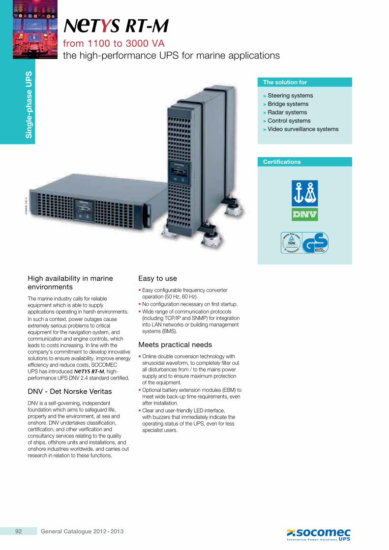
92 General Catalogue 2012 - 2013
Sin
gle
-pha
se U
PS
High availability in marine environments
The marine industry calls for reliable equipment which is able to supply applications operating in harsh environments.In such a context, power outages cause extremely serious problems to critical equipment for the navigation system, and communication and engine controls, which leads to costs increasing. In line with the company’s commitment to develop innovative solutions to ensure availability, improve energy efficiency and reduce costs, SOCOMEC UPS has introduced NeTYS RT-M, high-performance UPS DNV 2.4 standard certified.
DNV - Det Norske Veritas
DNV is a self-governing, independent foundation which aims to safeguard life, property and the environment, at sea and onshore. DNV undertakes classification, certification, and other verification and consultancy services relating to the quality of ships, offshore units and installations, and onshore industries worldwide, and carries out research in relation to these functions.
Easy to use
� Easy configurable frequency converter operation (50 Hz, 60 Hz).
� No configuration necessary on first startup.� Wide range of communication protocols
(including TCP/IP and SNMP) for integration into LAN networks or building management systems (BMS).
Meets practical needs
� Online double conversion technology with sinusoidal waveform, to completely filter out all disturbances from / to the mains power supply and to ensure maximum protection of the equipment.
� Optional battery extension modules (EBM) to meet wide back-up time requirements, even after installation.
� Clear and user-friendly LED interface, with buzzers that immediately indicate the operating status of the UPS, even for less specialist users.
N TYS RT-Mfrom 1100 to 3000 VAthe high-performance UPS for marine applications
The solution for
> Steering systems> Bridge systems> Radar systems> Control systems> Video surveillance systems
Certifications
Sin
gle
-pha
se U
PG
AM
ME
240
A
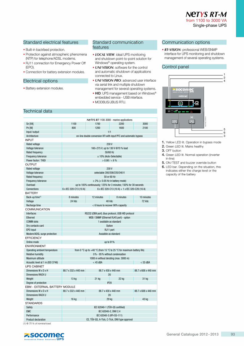
93General Catalogue 2012 - 2013
N TYS RT-M from 1100 to 3000 VA
Single-phase UPS
Technical data
NeTYS RT 1100-3000 - marine applicationsSn [VA] 1100 1700 2200 3000Pn [W] 800 1200 1600 2100Input / output 1/1Architecture on-line double conversion VFI with input PFC and automatic bypass
INPUTRated voltage 230 VVoltage tolerance 160÷275 V; up to 130 V @70 % loadRated frequency 50/60 HzFrequency tolerance ± 10% (Auto-Selectable)Power factor / THDI > 0.98 / < 6 %
OUTPUTRated voltage 230 VVoltage tolerance selectable 200/208/220/240 VRated frequency 50 or 60 HzFrequency tolerance ± 2% (± 0.05 Hz in battery mode)Overload up to 105% continuously; 125% for 3 minutes; 150% for 30 secondsConnections 6 x IEC 320-C13 (10 A) 6 x IEC 320-C13 (10 A) + 1 x IEC 320-C20 (16 A)
BATTERYBack-up time(1) 8 minutes 12 minutes 8 minutes 10 minutesVoltage 24 Vdc 48 Vdc 72 VdcRecharge time < 6 hours to recover 90% capacity
COMMUNICATIONInterfaces RS232 (DB9 port) Jbus protocol, USB HID protocolEthernet WEB / SNMP (Ethernet RJ45 port) - optionCOMM slots 1 available as standardDry contacts card OptionEPO input RJ11 portModem/ADSL surge protection Avaialble as standard
EFFICIENCYOnline mode up to 91%
ENVIRONMENTOperating ambient temperature Z'����!`�=��|"�!`,Z'��� �!`��� �!`Z�'��[���������'\��Z�;Relative humidity 0 % - 95 % without condensationMaximum altitude 1000 m without derating (max. 3000 m)Acoustic level at 1 m (ISO 3746) < 45 dBA < 55 dBA
UPS CABINETDimensions W x D x H 88.7 x 332 x 440 mm 88.7 x 430 x 440 mm 88.7 x 608 x 440 mmDimensions RACK U 2UWeight 13 kg 21 kg 22 kg 31 kgDegree of protection IP20
EBM - EXTERNAL BATTERY MODULEDimensions W x D x H 88.7 x 332 x 440 mm 88.7 x 430 x 440 mm 88.7 x 608 x 440 mmDimensions RACK U 2UWeight 16 kg 29 kg 43 kg
STANDARDSSafety IEC 62040-1 (TÜV-GS certified)EMC IEC 62040-2, DNV 2.4Performance IEC 62040-3 (VFI-SS-111)Product declaration CE, TÜV-GS, A-Tick, C-Tick, DNV type approval
(1) @ 75 % of nominal load.
Standard electrical features
� Built-in backfeed protection.� Protection against atmospheric phenomena
(NTP) for telephone/ADSL modems.� RJ11 connection for Emergency Power Off
(EPO).� Connection for battery extension modules.
Electrical options
� Battery extension modules.
1. Yellow LED lit. Operation in bypass mode2. Green LED lit. Mains healthy3. OFF button4. Green LED lit. Normal operation (inverter
in-line)5. ON / TEST and buzzer override button6. LED bar. Depending on the situation, this
indicates either the charge level or the capacity of the battery
NE
TYS
108
A
42
5
S 1
08A
S
6
SSN
ETY
S
3
1
Control panel
Standard communication features
� LOCAL VIEW: ideal UPS monitoring and shutdown point-to-point solution for Windows® operating system.
� UNI VISION: software for the control and automatic shutdown of applications connected to Linux.
� UNI VISION PRO: advanced user interface via serial link and multiple shutdown management for several operating systems.
� HID: UPS management based on Windows® embedded service - USB interface.
� MODBUS/JBUS RTU.
Communication options
� RT-VISION: professional WEB/SNMP interface for UPS monitoring and shutdown management of several operating systems.
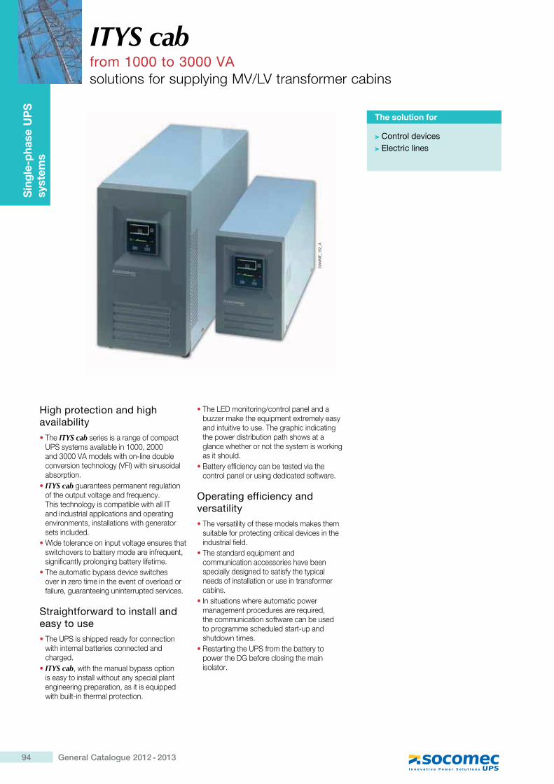
94 General Catalogue 2012 - 2013
Sin
gle-
phas
e U
PS
sy
stem
s
High protection and high availability� The ITYS cab series is a range of compact
UPS systems available in 1000, 2000 and 3000 VA models with on-line double conversion technology (VFI) with sinusoidal absorption.
� ITYS cab guarantees permanent regulation of the output voltage and frequency. This technology is compatible with all IT and industrial applications and operating environments, installations with generator sets included.
� Wide tolerance on input voltage ensures that switchovers to battery mode are infrequent, significantly prolonging battery lifetime.
� The automatic bypass device switches over in zero time in the event of overload or failure, guaranteeing uninterrupted services.
Straightforward to install and easy to use� The UPS is shipped ready for connection
with internal batteries connected and charged.
� ITYS cab, with the manual bypass option is easy to install without any special plant engineering preparation, as it is equipped with built-in thermal protection.
� The LED monitoring/control panel and a buzzer make the equipment extremely easy and intuitive to use. The graphic indicating the power distribution path shows at a glance whether or not the system is working as it should.
� Battery efficiency can be tested via the control panel or using dedicated software.
Operating efficiency and versatility� The versatility of these models makes them
suitable for protecting critical devices in the industrial field.
� The standard equipment and communication accessories have been specially designed to satisfy the typical needs of installation or use in transformer cabins.
� In situations where automatic power management procedures are required, the communication software can be used to programme scheduled start-up and shutdown times.
� Restarting the UPS from the battery to power the DG before closing the main isolator.
ITYS cabfrom 1000 to 3000 VAsolutions for supplying MV/LV transformer cabins
The solution for
> Control devices> Electric lines
GA
MM
E_1
52_A
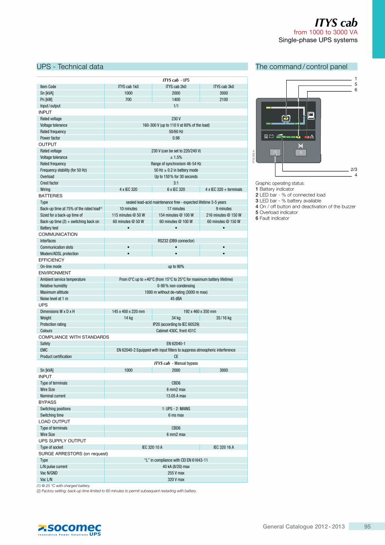
95General Catalogue 2012 - 2013
ITYS cab from 1000 to 3000 VA
Single-phase UPS systems
The command / control panel
Graphic operating status:1 Battery indicator2 LED bar - % of connected load3 LED bar - % battery available4 On / off button and deactivation of the buzzer5 Overload indicator6 Fault indicator
ITY
S 0
33 A
6
2/3224
51
UPS - Technical data
ITYS cab - UPSItem Code ITYS cab 1k0 ITYS cab 2k0 ITYS cab 3k0Sn [kVA] 1000 2000 3000Pn [kW] 700 1400 2100Input / output 1/1
INPUTRated voltage 230 VVoltage tolerance 160-300 V (up to 110 V at 60% of the load)Rated frequency 50/60 HzPower factor 0.98
OUTPUTRated voltage 230 V (can be set to 220/240 V)Voltage tolerance ± 1.5%Rated frequency Range of synchronism 46-54 HzFrequency stability (for 50 Hz) 50 Hz ± 0.2 in battery modeOverload Up to 150 % for 30 secondsCrest factor 3:1Wiring 4 x IEC 320 6 x IEC 320 4 x IEC 320 + terminals
BATTERIESType sealed lead-acid maintenance free - expected lifetime 3-5 yearsBack-up time at 75% of the rated load(1) 10 minutes 17 minutes 9 minutesSized for a back-up time of 115 minutes @ 50 W 154 minutes @ 100 W 216 minutes @ 150 WBack-up time (2) + switching back on 60 minutes @ 50 W 60 minutes @ 100 W 60 minutes @ 150 WBattery test � � �
COMMUNICATIONInterfaces RS232 (DB9 connector)Communication slots � � �Modem/ADSL protection � � �
EFFICIENCYOn-line mode up to 90%
ENVIRONMENTAmbient service temperature From 0°C up to +40°C (from 15°C to 25°C for maximum battery lifetime)Relative humidity 0-90 % non-condensingMaximum altitude 1000 m without de-rating (3000 m max)Noise level at 1 m 45 dBA
UPSDimensions W x D x H 145 x 400 x 220 mm 192 x 460 x 350 mmWeight 14 kg 34 kg 35 / 16 kgProtection rating IP20 (according to IEC 60529)Colours Cabinet 430C, front 431C
COMPLIANCE WITH STANDARDSSafety EN 62040-1EMC EN 62040-2 Equipped with input filters to suppress atmospheric interferenceProduct certification CE
ITYS cab - Manual bypass
Sn [kVA] 1000 2000 3000INPUTType of terminals CBD6Wire Size 6 mm2 maxNominal current 13.05 A max
BYPASSSwitching positions 1: UPS - 2: MAINSSwitching time 6 ms max
LOAD OUTPUTType of terminals CBD6Wire Size 6 mm2 max
UPS SUPPLY OUTPUTType of socket IEC 320 10 A IEC 320 16 A
SURGE ARRESTORS (on request)Type “L” in compliance with CEI EN 61643-11L/N pulse current 40 kA (8/20) maxVac N/GND 255 V maxVac L/N 320 V max
(1) @ 25 °C with charged battery.(2) Factory setting: back-up time limited to 60 minutes to permit subsequent restarting with battery.
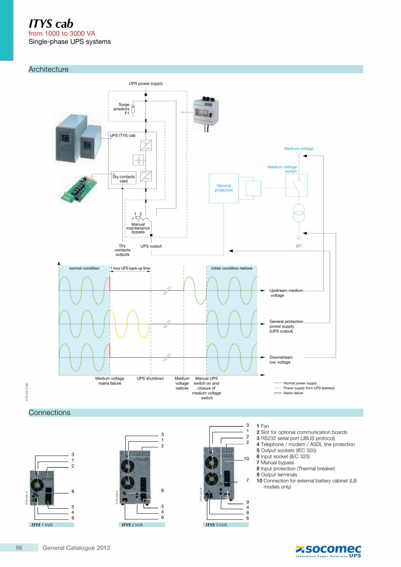
96 General Catalogue 2012
Architecture
ITYS cab from 1000 to 3000 VASingle-phase UPS systems
1 Fan2 Slot for optional communication boards3 RS232 serial port (JBUS protocol)4 Telephone / modem / ASDL line protection5 Output sockets (IEC 320)6 Input socket (IEC 320)7 Manual bypass8 Input protection (Thermal breaker)9 Output terminals10 ]����� �������� ������� ��������� >{|11 models only)12 1%
m
Connections
ITYS 1 kVA
ITY
S 0
05 A
213
546
8
ITYS 2 kVA
ITY
S 0
06 A
2
3
546
8
1
ITYS 3 kVA
ITY
S 0
04 B
3
948
10
1
22
6
7
21
Manualmaintenance
bypass
Surgearrestors
F1
UPS outputDrycontactsoutputs
UPS power supply
Dry contactscard
UPS ITYS cab
BT
Medium voltageswitch
Generalprotection
Medium voltage
initial condition restore
Medium voltagemains failure
Upstream medium voltage
General protection power supply (UPS output)
Downstream low voltage
1 hour UPS back-up timenormal condition
Power supply from UPS (battery)Normal power supply
Mains failure
UPS shutdown Mediumvoltagerestore
Manual UPS switch on and
closure of medium voltage
switch
ITY
S 0
32 A
GB
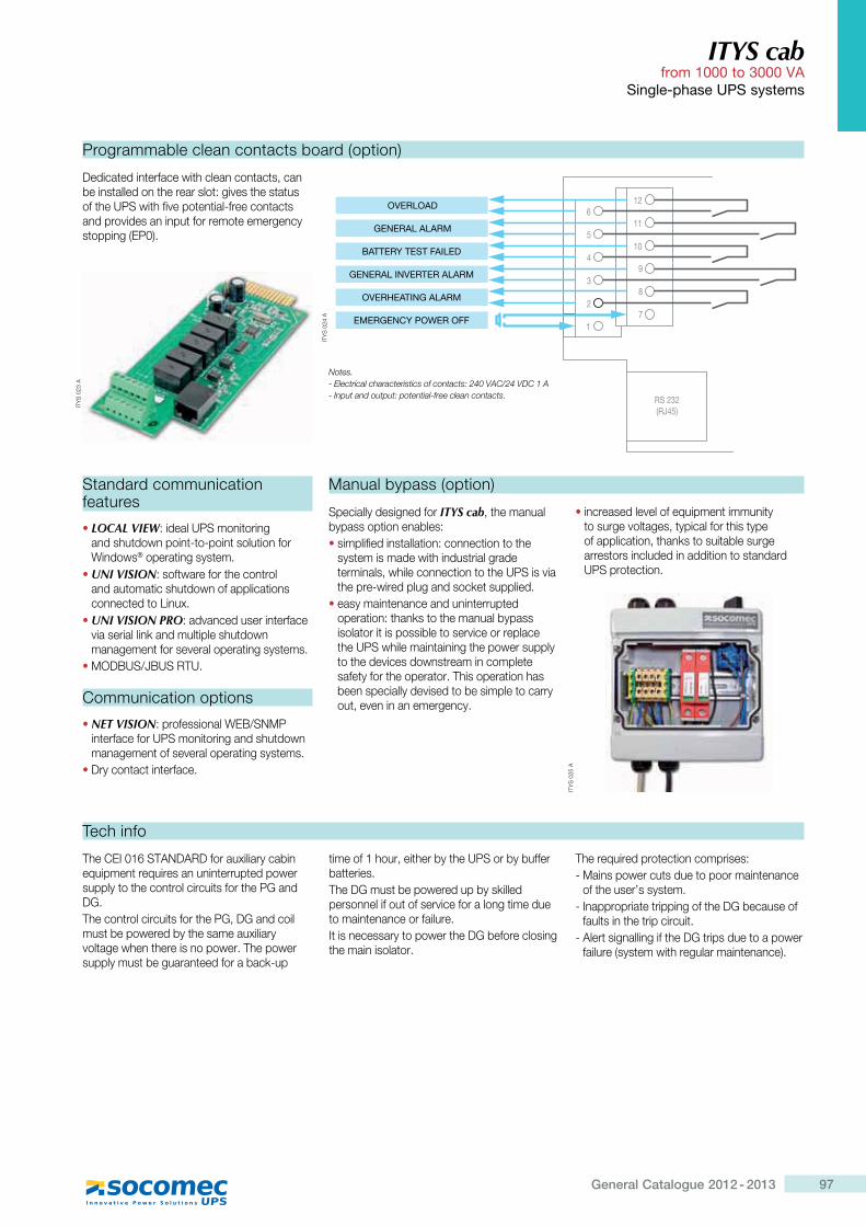
97General Catalogue 2012 - 2013
ITYS cab from 1000 to 3000 VA
Single-phase UPS systems
Programmable clean contacts board (option)
Dedicated interface with clean contacts, can be installed on the rear slot: gives the status of the UPS with five potential-free contacts and provides an input for remote emergency stopping (EP0).
ITY
S 0
23 A
1
2
3
4
5
6
7
RS 232(RJ45)
8
9
10
11
12OVERLOAD
GENERAL ALARM
BATTERY TEST FAILED
GENERAL INVERTER ALARM
OVERHEATING ALARM
EMERGENCY POWER OFFIT
YS
024
A
Standard communication features
� LOCAL VIEW: ideal UPS monitoring and shutdown point-to-point solution for Windows® operating system.
� UNI VISION: software for the control and automatic shutdown of applications connected to Linux.
� UNI VISION PRO: advanced user interface via serial link and multiple shutdown management for several operating systems.
� MODBUS/JBUS RTU.
Communication options
� NET VISION: professional WEB/SNMP interface for UPS monitoring and shutdown management of several operating systems.
� Dry contact interface.
Manual bypass (option)
Specially designed for ITYS cab, the manual bypass option enables:� simplified installation: connection to the
system is made with industrial grade terminals, while connection to the UPS is via the pre-wired plug and socket supplied.
� easy maintenance and uninterrupted operation: thanks to the manual bypass isolator it is possible to service or replace the UPS while maintaining the power supply to the devices downstream in complete safety for the operator. This operation has been specially devised to be simple to carry out, even in an emergency.
� increased level of equipment immunity to surge voltages, typical for this type of application, thanks to suitable surge arrestors included in addition to standard UPS protection.
ITY
S 0
25 A
Tech info
The CEI 016 STANDARD for auxiliary cabin equipment requires an uninterrupted power supply to the control circuits for the PG and DG.The control circuits for the PG, DG and coil must be powered by the same auxiliary voltage when there is no power. The power supply must be guaranteed for a back-up
time of 1 hour, either by the UPS or by buffer batteries.The DG must be powered up by skilled personnel if out of service for a long time due to maintenance or failure.It is necessary to power the DG before closing the main isolator.
The required protection comprises:- Mains power cuts due to poor maintenance
of the user’s system.- Inappropriate tripping of the DG because of
faults in the trip circuit.- Alert signalling if the DG trips due to a power
failure (system with regular maintenance).
Notes.- Electrical characteristics of contacts: 240 VAC/24 VDC 1 A- Input and output: potential-free clean contacts.
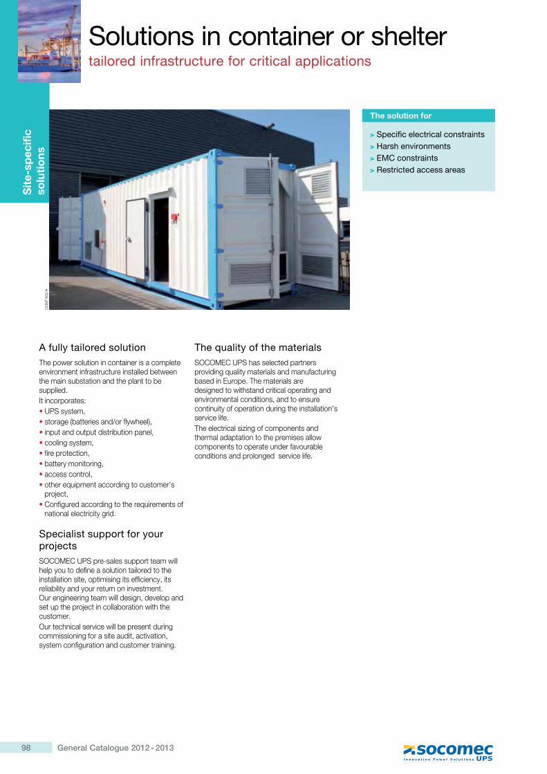
98 General Catalogue 2012 - 2013
Solutions in container or sheltertailored infrastructure for critical applications
Sit
e-sp
ecifi
c so
luti
ons
A fully tailored solutionThe power solution in container is a complete environment infrastructure installed between the main substation and the plant to be supplied.It incorporates:� UPS system,� storage (batteries and/or flywheel),� input and output distribution panel,� cooling system,� fire protection,� battery monitoring,� access control,� other equipment according to customer’s
project,� Configured according to the requirements of
national electricity grid.
Specialist support for your projectsSOCOMEC UPS pre-sales support team will help you to define a solution tailored to the installation site, optimising its efficiency, its reliability and your return on investment. Our engineering team will design, develop and set up the project in collaboration with the customer.Our technical service will be present during commissioning for a site audit, activation, system configuration and customer training.
The quality of the materialsSOCOMEC UPS has selected partners providing quality materials and manufacturing based in Europe. The materials are designed to withstand critical operating and environmental conditions, and to ensure continuity of operation during the installation’s service life.The electrical sizing of components and thermal adaptation to the premises allow components to operate under favourable conditions and prolonged service life.
The solution for
> Specific electrical constraints> Harsh environments> EMC constraints> Restricted access areas
CO
NT
003
A
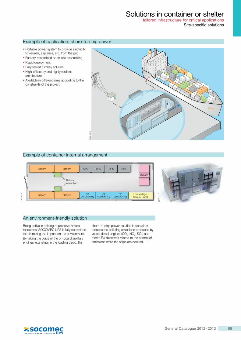
99General Catalogue 2012 - 2013
Solutions in container or shelter tailored infrastructure for critical applications
Site-specific solutions
An environment-friendly solution
Being active in helping to preserve natural resources, SOCOMEC UPS is fully committed to minimizing the impact on the environment.By taking the place of the on-board auxiliary engines (e.g. ships in the loading deck), the
shore-to-ship power solution in container reduces the polluting emissions produced by vessel diesel engines (CO2, NOX, SOX) and meets EU directives related to the control of emissions while the ships are docked.
Example of container internal arrangement
Battery Battery
Battery Battery Low Voltage Control Panel
Batteryprotection
UPS
Airconditioning
Airconditioning
Airconditioning
UPS UPS UPS
Bypass
CO
NT
002
A
CO
NT
001
A
� Portable power system to provide electricity to vessels, airplanes, etc. from the grid.
� Factory-assembled or on-site assembling.� Rapid deployment.� Fully tested turnkey solution.� High-efficiency and highly resilient
architecture.� Available in different sizes according to the
constraints of the project.
Example of application: shore-to-ship power
CO
NT
004
A


101General Catalogue 2012 - 2013
Communication and connectivity
Communication SoftwareManagement solutionsp.102
Communication InterfacesConnectivity solutionsp.107
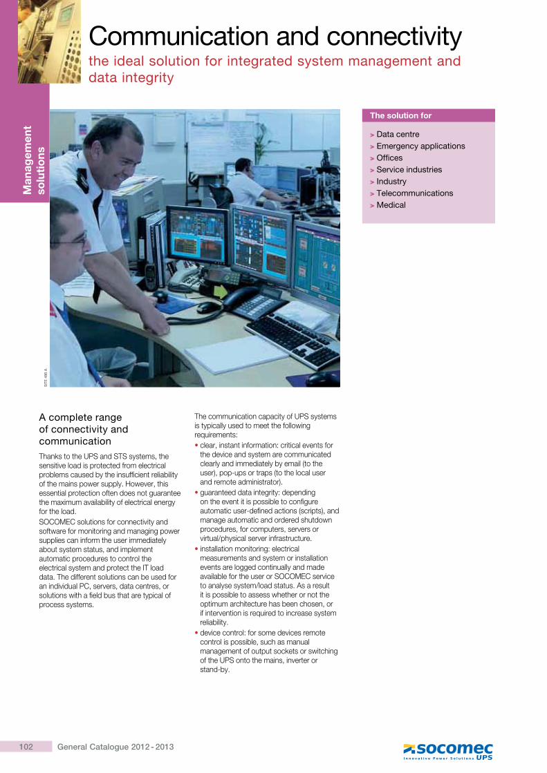
102 General Catalogue 2012 - 2013
Man
agem
ent
solu
tio
ns
A complete range of connectivity and communicationThanks to the UPS and STS systems, the sensitive load is protected from electrical problems caused by the insufficient reliability of the mains power supply. However, this essential protection often does not guarantee the maximum availability of electrical energy for the load.SOCOMEC solutions for connectivity and software for monitoring and managing power supplies can inform the user immediately about system status, and implement automatic procedures to control the electrical system and protect the IT load data. The different solutions can be used for an individual PC, servers, data centres, or solutions with a field bus that are typical of process systems.
The communication capacity of UPS systems is typically used to meet the following requirements:� clear, instant information: critical events for
the device and system are communicated clearly and immediately by email (to the user), pop-ups or traps (to the local user �������� �������� �� ��K�
� guaranteed data integrity: depending on the event it is possible to configure automatic user-defined actions (scripts), and manage automatic and ordered shutdown procedures, for computers, servers or virtual/physical server infrastructure.
� installation monitoring: electrical measurements and system or installation events are logged continually and made available for the user or SOCOMEC service to analyse system/load status. As a result it is possible to assess whether or not the optimum architecture has been chosen, or if intervention is required to increase system reliability.
� device control: for some devices remote control is possible, such as manual management of output sockets or switching of the UPS onto the mains, inverter or stand-by.
Communication and connectivitythe ideal solution for integrated system management and data integrity
The solution for
> Data centre> Emergency applications> Offices> Service industries> Industry> Telecommunications> Medical
SIT
E 4
86 A
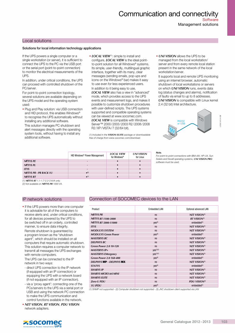
103General Catalogue 2012 - 2013
Communication and connectivity Software
Management solutions
If the UPS powers a single computer or a single workstation (or server), it is sufficient to connect the UPS to the PC via the USB port or the serial port (point-to-point connection) to monitor the electrical measurements of the UPS.In addition, under critical conditions, the UPS can proceed with controlled shutdown of the PC/server.For point-to-point connection topology, several solutions are available depending on the UPS model and the operating system used:� Plug and Play solution: via USB connection
and HID protocol, this enables Windows®
to recognise the UPS automatically without installing any additional software.This solution manages PC shutdown and alert messages directly with the operating system tools, without having to install any additional software.
� LOCAL VIEW(1): simple to install and configure, LOCAL VIEW is the ideal point-to-point solution for all Windows® systems. Its simple, user-friendly, multilingual graphic interface, together with its many, clear messages (sending emails, pop-ups and icons on the Windows® bar) makes it easy to use even for less experienced users.In addition to it being easy to use, LOCAL VIEW also has a view in “advanced” mode, which provides access to the UPS events and measurement logs, and makes it possible to customize shutdown procedures with user-defined scripts. The UPS systems supported and compatible operating systems can be viewed at www.socomec.com. LOCAL VIEW is compatible with Windows Server™ 2000 / 2003 / 2003 R2 / 2008 / 2008 R2 / XP / VISTA / 7 (32/64 bit).
� UNI VISION allows the UPS to be managed from the local workstation/server and from every remote local station present in the same network of the local workstation/server.It supports local and remote UPS monitoring using an internet browser, automatic shutdown of local workstations or servers on which UNI VISION runs, events data log (status changes and alarms), notification of faults via email to up to 8 addresses. UNI VISION is compatible with Linux kernel 2.4 (32 bit) Intel architecture.
Local solutions
RS232or USB
LOG
IC 0
15 A
GB
Solutions for local information technology applications
HID Windows® Power Management LOCAL VIEW for Windows®
UNI VISION for Linux
N TYS PE - � �N TYS PL - � �ITYS - � �N TYS PR - PR RACK 1U �(2) � �N TYS RT �(1) � �
(1) N TYS RT 1.1-1.7-2.2-3 kVA only.(2) Not available on N TYS PR 1000 VA.
� If the UPS powers more than one computer it is advisable for all of the computers to receive alerts and, under critical conditions, for all devices powered by the UPS to be switched off in an orderly, controlled manner, to ensure data integrity.Remote shutdown is guaranteed by a program known as the “shutdown agent”, which should be installed on all computers that require automatic shutdown. @[������� ����������������� ���� ���Q �transmit all messages the UPS exchanges with remote computers.The UPS can be connected to the IP network in two ways:- direct UPS connection to the IP network
(if equipped with an IP connection) or equipping the UPS with a network board >����� ���������� [��?������� ���K�
- via a ‘proxy agent’: connecting one of the PCs/servers to the UPS via a serial port or USB and using the network PC connection to make the UPS communication and control functions available in the network.
� NET VISION, RT VISION, PDU VISION network adapters.
IP network solutions
Note.For point-to-point connections with IBM-AIX, HP-UX, Sun Solaris and Novell operating systems, UNI VISION PRO software must be used.
(1) Included in the VISION-SUITE package or downloadable free of charge from www.socomec.com/download.
Product Embedded LAN Optional advanced LAN
N TYS PR no NET VISION(3)
N TYS RT 1100-3000 no RT VISION(3)
N TYS RT 5000-11000 yes(3) embedded(3)
ITYS no NET VISION(3)
MODULYS SYSTEM no NET VISION(3)
MODULYS Green Power yes(3) embedded(3)
MASTERYS BC no NET VISION(3)
DELPHYS BC no NET VISION(3)
Green Power 2.0 10-120 no NET VISION(3)
MASTERYS IP+ yes(1)(2) NET VISION(3)
MASTERYS EMergency yes(1)(2) NET VISION(3)
Green Power 2.0 160-400 yes(3) embedded(3)
DELPHYS MP - DELPHYS MX no NET VISION(3)
STATYS yes(2) embedded(2)
SHARYS IP no NET VISION(3)
SHARYS MICRO and MINI no NET VISION(3)
SHARYS ELITE no NET VISION(3)
Zero-U PDU no PDU VISION(2)
1U iPDU yes(2) embedded(2)
(1) SNMP not supported - (2) Computer shutdown not supported - (3) JNC shutdown client supported via LAN
Connection of SOCOMEC devices to the LAN
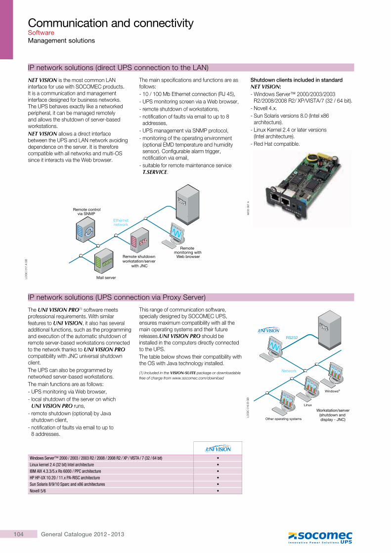
104 General Catalogue 2012 - 2013
NET VISION is the most common LAN interface for use with SOCOMEC products. It is a communication and management interface designed for business networks. The UPS behaves exactly like a networked peripheral, it can be managed remotely and allows the shutdown of server-based workstations.NET VISION allows a direct interface between the UPS and LAN network avoiding dependence on the server. It is therefore compatible with all networks and multi-OS since it interacts via the Web browser.
The main specifications and functions are as follows:- 10 / 100 Mb Ethernet connection (RJ 45),- UPS monitoring screen via a Web browser,- remote shutdown of workstations,- notification of faults via email to up to 8
addresses,- UPS management via SNMP protocol,- monitoring of the operating environment
(optional EMD temperature and humidity sensor). Configurable alarm trigger, notification via email,
- suitable for remote maintenance service T.SERVICE.
Shutdown clients included in standard NET VISION:- Windows Server™ 2000/2003/2003
R2/2008/2008 R2/ XP/VISTA/7 (32 / 64 bit).- Novell 4.x.- Sun Solaris versions 8.0 (Intel x86
architecture).- Linux Kernel 2.4 or later versions
>?� ������[� �� ���K�- Red Hat compatible.
Communication and connectivitySoftwareManagement solutions
Ethernetnetwork
Remotemonitoring with
Web browserRemote shutdown workstation/server
with JNC
Mail server
Remote controlvia SNMP
LOG
IC 0
17 A
GB
IP network solutions (direct UPS connection to the LAN)
MO
D 0
67 A
The UNI VISION PRO(1) software meets professional requirements. With similar features to UNI VISION, it also has several additional functions, such as the programming and execution of the automatic shutdown of remote server-based workstations connected to the network thanks to UNI VISION PRO compatibility with JNC universal shutdown client.The UPS can also be programmed by networked server-based workstations.The main functions are as follows:- UPS monitoring via Web browser,- local shutdown of the server on which
UNI VISION PRO runs,- remote shutdown (optional) by Java
shutdown client,- notification of faults via email to up to
������������
This range of communication software, specially designed by SOCOMEC UPS, ensures maximum compatibility with all the main operating systems and their future releases.UNI VISION PRO should be installed in the computers directly connected to the UPS.The table below shows their compatibility with the OS with Java technology installed.
(1) Included in the VISION-SUITE package or downloadable free of charge from www.socomec.com/download
Windows Server™ 2000 / 2003 / 2003 R2 / 2008 / 2008 R2 / XP / VISTA / 7 (32 / 64 bit) �Linux kernel 2.4 (32 bit) Intel architecture �IBM AIX 4.3.3/5.x Rs 6000 / PPC architecture �HP HP-UX 10.20 / 11.x PA-RISC architecture �Sun Solaris 8/9/10 Sparc and x86 architectures �Novell 5/6 �
IP network solutions (UPS connection via Proxy Server)
Network
RS232
Other operating systems
Linux
Windows®
������
� ��
������
� ��
������
� ��
Workstation/server(shutdown and display - JNC)
LOG
IC 0
16 B
GB
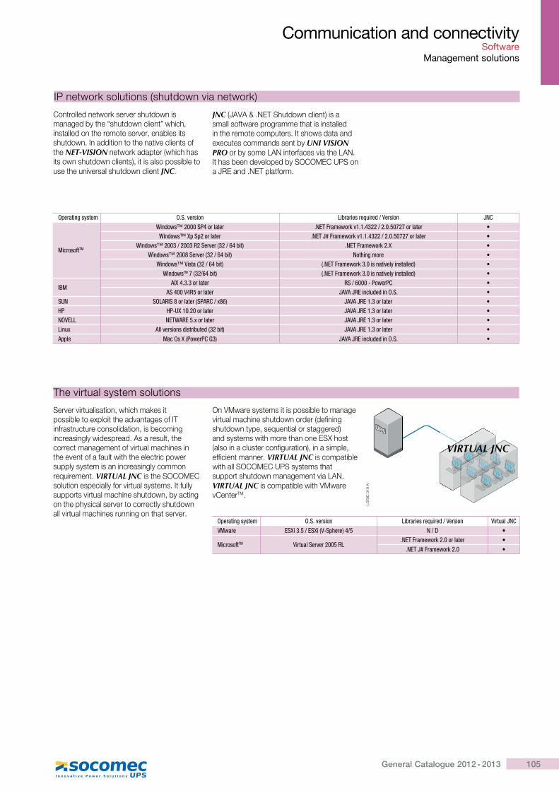
105General Catalogue 2012 - 2013
Server virtualisation, which makes it possible to exploit the advantages of IT infrastructure consolidation, is becoming increasingly widespread. As a result, the correct management of virtual machines in the event of a fault with the electric power supply system is an increasingly common requirement. VIRTUAL JNC is the SOCOMEC solution especially for virtual systems. It fully supports virtual machine shutdown, by acting on the physical server to correctly shutdown all virtual machines running on that server.
On VMware systems it is possible to manage virtual machine shutdown order (defining shutdown type, sequential or staggered) and systems with more than one ESX host (also in a cluster configuration), in a simple, efficient manner. VIRTUAL JNC is compatible with all SOCOMEC UPS systems that support shutdown management via LAN. VIRTUAL JNC is compatible with VMware vCenterTM.
LOG
IC 0
19 A
VIRTUAL JNC
Communication and connectivity Software
Management solutions
The virtual system solutions
Operating system O.S. version Libraries required / Version Virtual JNC VMware ESXi 3.5 / ESXi (V-Sphere) 4/5 N / D �
MicrosoftTM Virtual Server 2005 RL.NET Framework 2.0 or later �
.NET J# Framework 2.0 �
Operating system O.S. version Libraries required / Version JNC
MicrosoftTM
Windows™ 2000 SP4 or later .NET Framework v1.1.4322 / 2.0.50727 or later �Windows™ Xp Sp2 or later .NET J# Framework v1.1.4322 / 2.0.50727 or later �
Windows™ 2003 / 2003 R2 Server (32 / 64 bit) .NET Framework 2.X �Windows™ 2008 Server (32 / 64 bit) Nothing more �
Windows™ Vista (32 / 64 bit) (.NET Framework 3.0 is natively installed) �WindowsTM 7 (32/64 bit) (.NET Framework 3.0 is natively installed) �
IBMAIX 4.3.3 or later RS / 6000 - PowerPC �
AS 400 V4R5 or later JAVA JRE included in O.S. �SUN SOLARIS 8 or later (SPARC / x86) JAVA JRE 1.3 or later �HP HP-UX 10.20 or later JAVA JRE 1.3 or later �NOVELL NETWARE 5.x or later JAVA JRE 1.3 or later �Linux All versions distributed (32 bit) JAVA JRE 1.3 or later �Apple Mac Os X (PowerPC G3) JAVA JRE included in O.S. �
Controlled network server shutdown is managed by the “shutdown client” which, installed on the remote server, enables its shutdown. In addition to the native clients of the NET-VISION network adapter (which has its own shutdown clients), it is also possible to use the universal shutdown client JNC.
JNC (JAVA & .NET Shutdown client) is a small software programme that is installed in the remote computers. It shows data and executes commands sent by UNI VISION PRO or by some LAN interfaces via the LAN. It has been developed by SOCOMEC UPS on a JRE and .NET platform.
IP network solutions (shutdown via network)
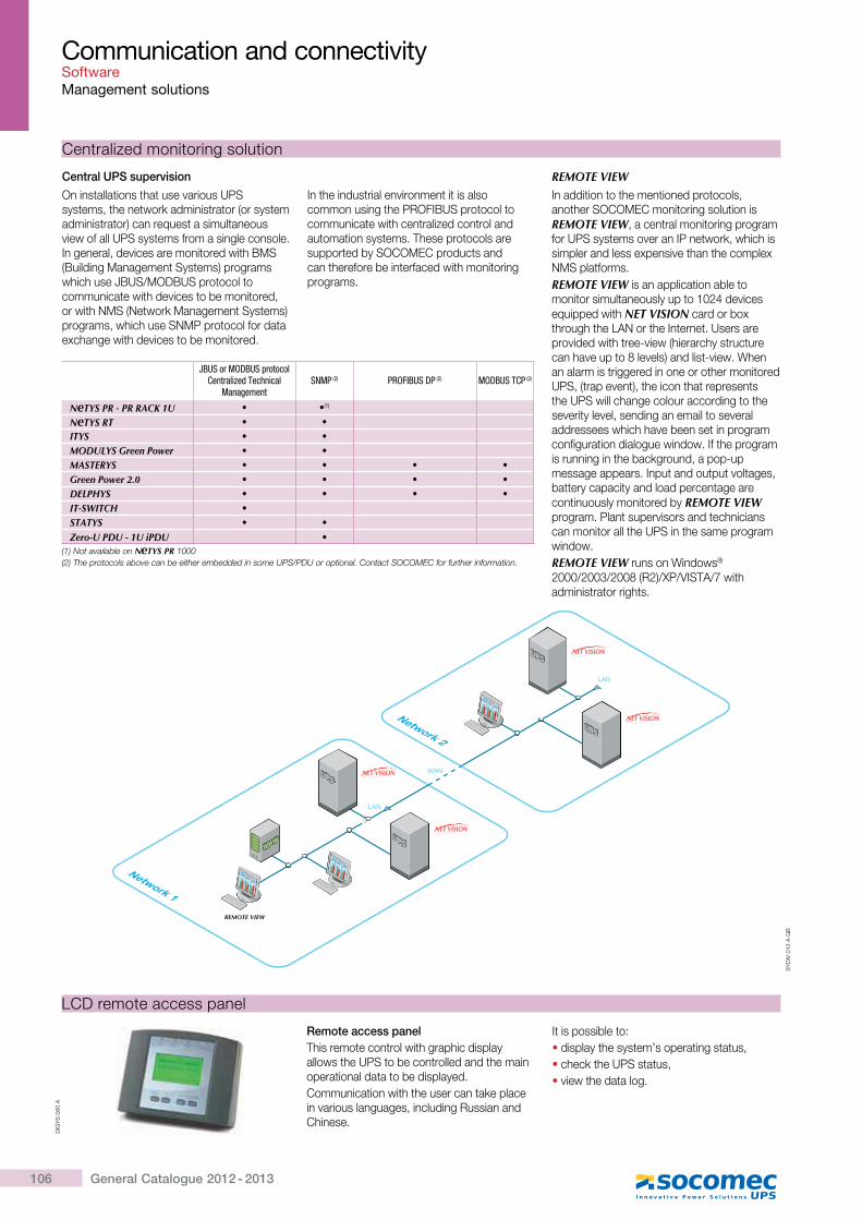
106 General Catalogue 2012 - 2013
Communication and connectivity SoftwareManagement solutions
On installations that use various UPS systems, the network administrator (or system administrator) can request a simultaneous view of all UPS systems from a single console. In general, devices are monitored with BMS (Building Management Systems) programs which use JBUS/MODBUS protocol to communicate with devices to be monitored, or with NMS (Network Management Systems) programs, which use SNMP protocol for data exchange with devices to be monitored.
In the industrial environment it is also common using the PROFIBUS protocol to communicate with centralized control and automation systems. These protocols are supported by SOCOMEC products and can therefore be interfaced with monitoring programs.
Centralized monitoring solution
Central UPS supervision REMOTE VIEWIn addition to the mentioned protocols, another SOCOMEC monitoring solution is REMOTE VIEW, a central monitoring program for UPS systems over an IP network, which is simpler and less expensive than the complex NMS platforms.REMOTE VIEW is an application able to monitor simultaneously up to 1024 devices equipped with NET VISION card or box through the LAN or the Internet. Users are provided with tree-view (hierarchy structure can have up to 8 levels) and list-view. When an alarm is triggered in one or other monitored UPS, (trap event), the icon that represents the UPS will change colour according to the severity level, sending an email to several addressees which have been set in program configuration dialogue window. If the program is running in the background, a pop-up message appears. Input and output voltages, battery capacity and load percentage are continuously monitored by REMOTE VIEW program. Plant supervisors and technicians can monitor all the UPS in the same program window.REMOTE VIEW runs on Windows® 2000/2003/2008 (R2)/XP/VISTA/7 with administrator rights.
SY
DIV
013
A G
B
Network 1
LAN
WAN
LAN
REMOTE VIEW
Network 2
������
� ��
������
� ��
������
� ��
JBUS or MODBUS protocol Centralized Technical
ManagementSNMP (2) PROFIBUS DP (2) MODBUS TCP (2)
NeTYS PR - PR RACK 1U � �(1)
NeTYS RT � �ITYS � �MODULYS Green Power � �MASTERYS � � � �Green Power 2.0 � � � �DELPHYS � � � �IT-SWITCH �STATYS � �
Zero-U PDU - 1U iPDU �(1) Not available on N TYS PR 1000(2) The protocols above can be either embedded in some UPS/PDU or optional. Contact SOCOMEC for further information.
DIG
YS
060
A
LCD remote access panel
Remote access panelThis remote control with graphic display allows the UPS to be controlled and the main operational data to be displayed.Communication with the user can take place in various languages, including Russian and Chinese.
It is possible to:� display the system’s operating status,� check the UPS status,� view the data log.
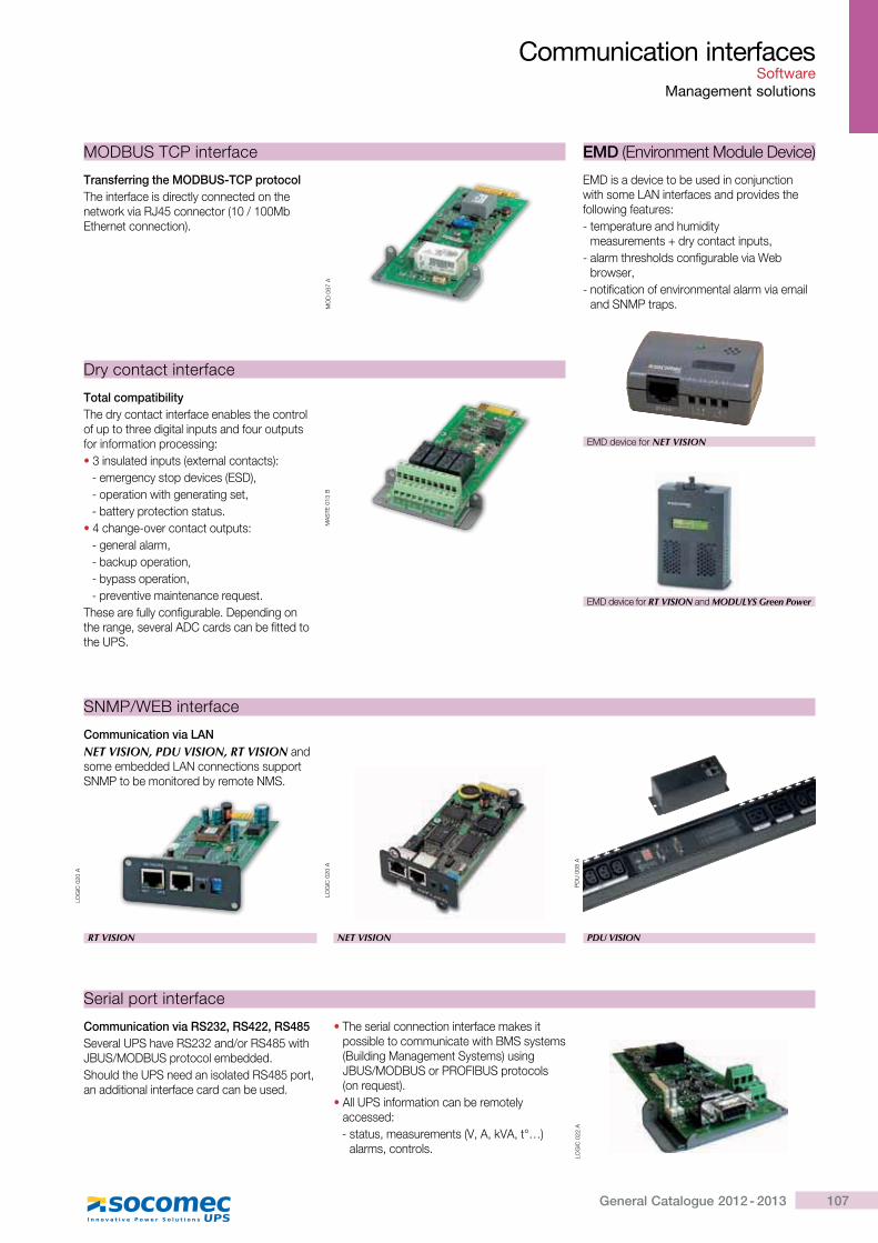
107General Catalogue 2012 - 2013
Communication interfaces Software
Management solutions
EMD (Environment Module Device)
MA
STE
013
B
Total compatibilityThe dry contact interface enables the control of up to three digital inputs and four outputs for information processing:� 3 insulated inputs (external contacts):
- emergency stop devices (ESD),- operation with generating set,- battery protection status.
� 4 change-over contact outputs:- general alarm,- backup operation,- bypass operation,- preventive maintenance request.
These are fully configurable. Depending on the range, several ADC cards can be fitted to the UPS.
Dry contact interface
EMD is a device to be used in conjunction with some LAN interfaces and provides the following features:- temperature and humidity
���������� ���������� �� ���� ��- alarm thresholds configurable via Web
browser,- notification of environmental alarm via email
and SNMP traps.
EMD device for NET VISION
EMD device for RT VISION and MODULYS Green Power
MODBUS TCP interface
Transferring the MODBUS-TCP protocolThe interface is directly connected on the network via RJ45 connector (10 / 100Mb Ethernet connection).
MO
D 0
67 A
LOG
IC 0
20 A
Communication via LANNET VISION, PDU VISION, RT VISION and some embedded LAN connections support SNMP to be monitored by remote NMS.
SNMP/WEB interface
RT VISION PDU VISION
PD
U 0
08 A
LOG
IC 0
20 A
NET VISION
Communication via RS232, RS422, RS485Several UPS have RS232 and/or RS485 with JBUS/MODBUS protocol embedded.Should the UPS need an isolated RS485 port, an additional interface card can be used.
� The serial connection interface makes it possible to communicate with BMS systems (Building Management Systems) using JBUS/MODBUS or PROFIBUS protocols (on request).
� All UPS information can be remotely accessed:- status, measurements (V, A, kVA, t°…)
alarms, controls.
Serial port interface
LOG
IC 0
22 A

© A
nton
is P
apan
toni
ou -
Fot
olia
.com
109General Catalogue 2012 - 2013
Technology
The answer to your needsp.110
High quality voltagep.111
Architecturesp.113
Economical operationp.116
UPS interfacesp.117
110 General Catalogue 2012 - 2013
Tech
nolo
gy
The answer to your needssolutions adaptedto your applications, to your environment and to your operating constraints
Innovative solutions� To meet your supply needs for critical
equipment, SOCOMEC UPS offers solutions drawn from extensive experience with high quality power supplies using the latest technology.
� Green Power 2.0: full rated power available thanks to Power Factor 1 (kW=kVA) that requires no power downgrading when supplying the latest generation of servers in typical data centre conditions.
High quality power supply� Precise voltage produced by means of
digital control.� Adapted to non-linear loads.� Compatible, without derating, with the
latest IT-loads having high and leading power factor.
An infrastructure reduced in size and cost� Integration into your environment is
simplified by using rectifiers delivering a sinusoidal current that eliminates the constraints caused by harmonics and limiting the current used upstream.
� High power factor upstream of the rectifiers allows the cable diameter and protection level to be reduced.
� Optimal power sizing of the transformer source or the generator set.
� High short-circuit current, simplifying the protection needed to maintain selectivity upstream.
� Optimal size and front access reduces the impact on space requirements.
A progressive investment� Modular UPS and parallel modular
configurations make it possible to spread your power investment over time and according to your needs, by upgrading your existing equipment.
� Real hot-swap pluggable power modules allow power upgrading and maintenance without affecting the system availability.
Reduction in operating costs� High efficiency online reduces your
electricity bill by reducing not only the electricity needed to supply the UPS but also the electricity required for cooling or air conditioning.
� Energy Saver system that optimizes the efficiency of the UPS in parallel when operating with a partial load.
� Fast EcoMode, automatic operating mode that optimizes the efficiency depending on the quality of the input voltage.
Simplified operations� Design that allows the architecture to
be adapted to your own specifications concerning: redundancy, energy storage, specific configurations and connection with static transfer systems.
� Installation and connection on your facilities.
� Interfaces and software allowing local and remote monitoring of your equipment.
Constant availability of your power supply� Fault-tolerant design with numerous
redundant functions.� Battery reliability over time using an
innovative charging system.� Permanent monitoring of the battery
system and simplified maintenance.
Accurate diagnostics and maintenance� Operating status shown on a control
and monitoring panel.� Remote monitoring and teleservice.� Easily accessible components and
subassemblies, reducing repair time.� Preventive maintenance.
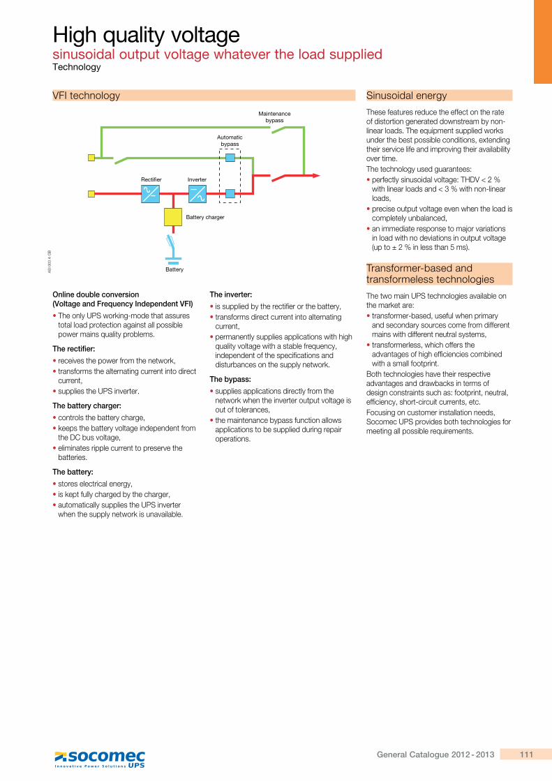
111General Catalogue 2012 - 2013
High quality voltage sinusoidal output voltage whatever the load suppliedTechnology
Online double conversion (Voltage and Frequency Independent VFI)
� The only UPS working-mode that assures total load protection against all possible power mains quality problems.
The rectifier:
� receives the power from the network,� transforms the alternating current into direct
current,� supplies the UPS inverter.
The battery charger:
� controls the battery charge,� keeps the battery voltage independent from
the DC bus voltage,� eliminates ripple current to preserve the
batteries.
The battery:
� stores electrical energy,� is kept fully charged by the charger,� automatically supplies the UPS inverter
when the supply network is unavailable.
The inverter:
� is supplied by the rectifier or the battery,� transforms direct current into alternating
current,� permanently supplies applications with high
quality voltage with a stable frequency, independent of the specifications and disturbances on the supply network.
The bypass:
� supplies applications directly from the network when the inverter output voltage is out of tolerances,
� the maintenance bypass function allows applications to be supplied during repair operations.
VFI technology
Automaticbypass
Maintenancebypass
Rectifier
Battery charger
Inverter
BatteryAS
I 003
A G
B
Sinusoidal energy
These features reduce the effect on the rate of distortion generated downstream by non-linear loads. The equipment supplied works under the best possible conditions, extending their service life and improving their availability over time.The technology used guarantees:� perfectly sinusoidal voltage: THDV < 2 %
with linear loads and < 3 % with non-linear loads,
� precise output voltage even when the load is completely unbalanced,
� an immediate response to major variations in load with no deviations in output voltage (up to ± 2 % in less than 5 ms).
Transformer-based and transformeless technologies
The two main UPS technologies available on the market are:� transformer-based, useful when primary
and secondary sources come from different mains with different neutral systems,
� transformerless, which offers the advantages of high efficiencies combined with a small footprint.
Both technologies have their respective advantages and drawbacks in terms of design constraints such as: footprint, neutral, efficiency, short-circuit currents, etc.Focusing on customer installation needs, Socomec UPS provides both technologies for meeting all possible requirements.
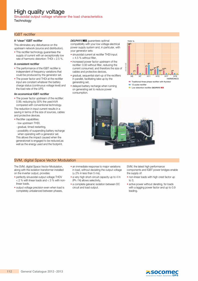
112 General Catalogue 2012 - 2013
A “clean” IGBT rectifier
This eliminates any disturbance on the upstream network (source and distribution).� This rectifier technology guarantees the
supply of current with an exceptionally low rate of harmonic distortion: THDI < 2.5 %.
A consistent rectifier
� The performance of the IGBT rectifier is independent of frequency variations that could be produced by the generator set.
� The power factor and THDI at the rectifier input are constant whatever the battery charge status (continuous voltage level) and the load rate of the UPS.
An economical IGBT rectifier
� The power factor upstream of the rectifier: 0.99, reducing by 30% the used kVA compared with conventional technology.
The reduction in input current results in a saving in terms of the size of sources, cables and protective devices.� Rectifier capabilities:
- low upstream THDI,- gradual, timed restarting,- possibility of suspending battery recharge
when operating with a generator set.This allows the impact caused when the generatorset is engaged to be reduced,as well as the energy used and the footprint.
DELPHYS MX guarantees optimal compatibility with your low voltage electrical power supply system and, in particular, with your generator sets:� sinusoidal current at rectifier THDI input:
¥�'�\��� [�� ��� ���� increased power factor upstream of the
rectifier: 0.93 without filter, reducing the current consumed, and therefore the size of cables and protective devices,
� gradual, sequential start-up of the rectifiers in parallel, facilitating take up by the generating set,
� delayed battery recharge when running on generating set to reduce power consumption.
High quality voltageSinusoidal output voltage whatever the load characteristicsTechnology
IGBT rectifier
The SVM, digital Space Vector Modulation, along with the isolation transformer installed on the inverter output, provides:� perfectly sinusoidal output voltage THDV
¥�*��� [��������������¥Z��� [���Xlinear loads,
� output voltage precision even when load is completely unbalanced between phases,
� an immediate response to major variations in load, without deviating the output voltage (± 2% in less than 5 ms),
��^���[�[�[�� X������ ������ ��� �'?�(Ph / N) allows selectivity,
� a complete galvanic isolation between DC circuit and load output.
SVM, the latest high performance components and IGBT power bridges enable the supply of:� non-linear loads with high crest factor up
to 3,� active power without derating, for loads
with a lagging power factor and up to 0.9 leading.
SVM, digital Space Vector Modulation
DE
FYS
127
A 1
CA
T
H5 H7 H11 H13 H17 H19
@����� ��������#�������������������������� �
_{#��������������
} ������ ��� �����������DELPHYS MX
HARMONICS
THDI %
28 %
1 %
8 %7 %
9 %
5 % 6 %
3,2 % 2,5 %4,7 %
2 %AS
I 008
A G
B
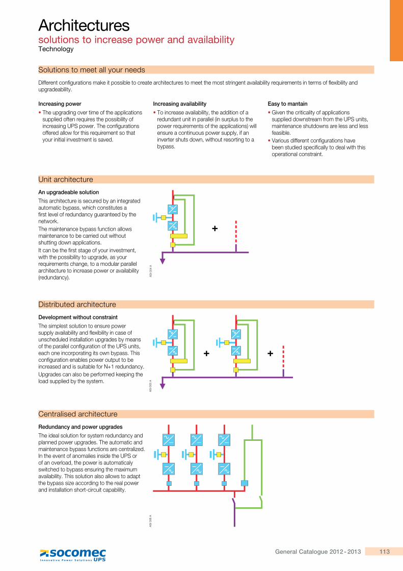
113General Catalogue 2012 - 2013
Different configurations make it possible to create architectures to meet the most stringent availability requirements in terms of flexibility and upgradeability.
Solutions to meet all your needs
Architectures solutions to increase power and availabilityTechnology
Increasing power
� The upgrading over time of the applications supplied often requires the possibility of increasing UPS power. The configurations offered allow for this requirement so that your initial investment is saved.
Increasing availability
� To increase availability, the addition of a redundant unit in parallel (in surplus to the power requirements of the applications) will ensure a continuous power supply, if an inverter shuts down, without resorting to a bypass.
Easy to mantain
� Given the criticality of applications supplied downstream from the UPS units, maintenance shutdowns are less and less feasible.
� Various different configurations have been studied specifically to deal with this operational constraint.
An upgradeable solution
This architecture is secured by an integrated automatic bypass, which constitutes a first level of redundancy guaranteed by the network.The maintenance bypass function allows maintenance to be carried out without shutting down applications.It can be the first stage of your investment, with the possibility to upgrade, as your requirements change, to a modular parallel architecture to increase power or availability (redundancy).
Unit architecture
Development without constraint
The simplest solution to ensure power supply availability and flexibility in case of unscheduled installation upgrades by means of the parallel configuration of the UPS units, each one incorporating its own bypass. This configuration enables power output to be increased and is suitable for N+1 redundancy.Upgrades can also be performed keeping the load supplied by the system.
Distributed architecture
Redundancy and power upgrades
The ideal solution for system redundancy and planned power upgrades. The automatic and maintenance bypass functions are centralized. In the event of anomalies inside the UPS or of an overload, the power is automaticaly switched to bypass ensuring the maximum availability. This solution also allows to adapt the bypass size according to the real power and installation short-circuit capability.
Centralised architecture
AS
I 005
AA
SI 0
06 A
�~
?##'
�
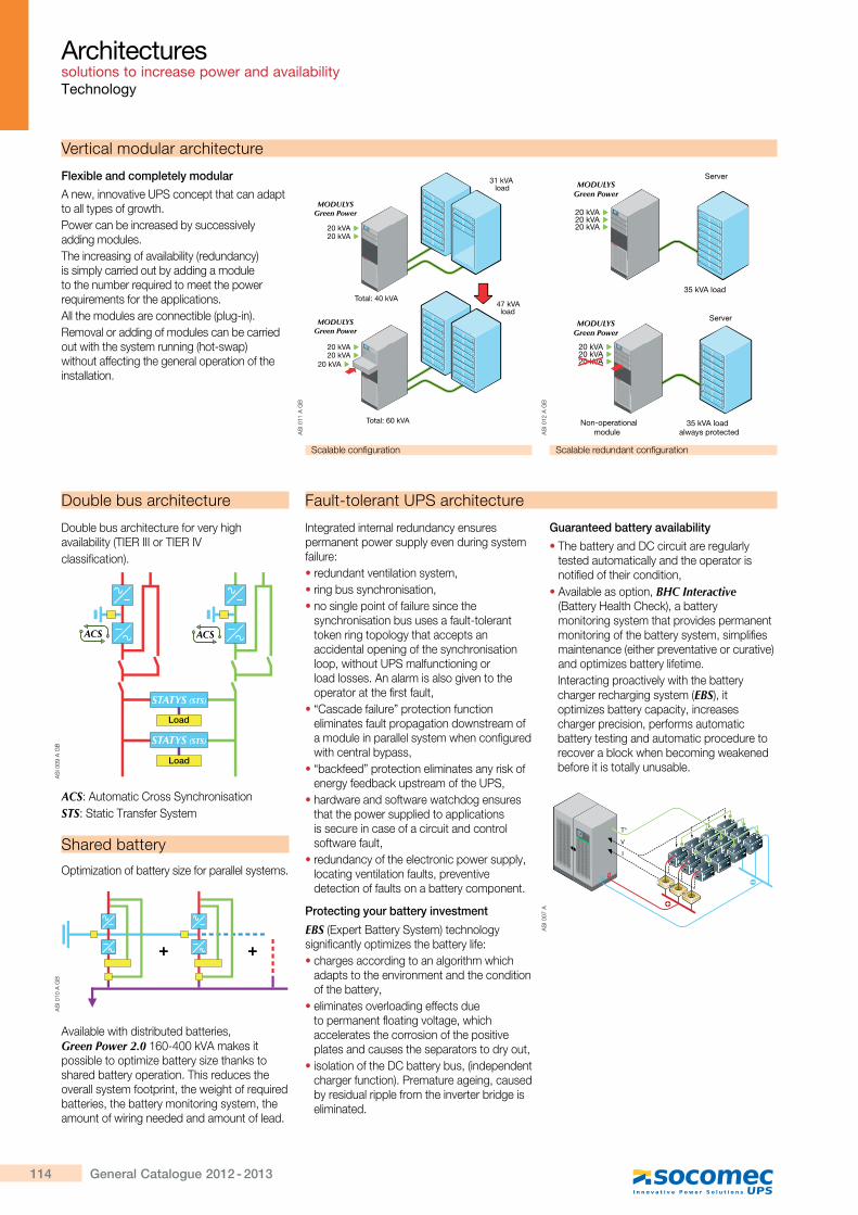
114 General Catalogue 2012 - 2013
Architectures solutions to increase power and availabilityTechnology
A new, innovative UPS concept that can adapt to all types of growth.Power can be increased by successively adding modules.The increasing of availability (redundancy) is simply carried out by adding a module to the number required to meet the power requirements for the applications.All the modules are connectible (plug-in).Removal or adding of modules can be carried out with the system running (hot-swap) without affecting the general operation of the installation.
Vertical modular architecture
Flexible and completely modular
Scalable configuration Scalable redundant configuration
20 kVA
Server
Server
35 kVA load
35 kVA loadalways protected
Non-operationalmodule
20 kVA20 kVA MODULYS Green Power
20 kVA20 kVA20 kVA
MODULYS Green Power
MODULYSGreen Power
MODULYSGreen Power
47 kVA load
31 kVAload
Total: 40 kVA
20 kVA20 kVA
20 kVA20 kVA
20 kVA
MODULYSGreen Power
MODULYSGreen Power
Total: 60 kVA
MODULYS Green Power
MODULYS Green Power
AS
I 011
A G
B
AS
I 012
A G
B
Fault-tolerant UPS architecture
Integrated internal redundancy ensures permanent power supply even during system failure:� redundant ventilation system,� ring bus synchronisation,� no single point of failure since the
synchronisation bus uses a fault-tolerant token ring topology that accepts an accidental opening of the synchronisation loop, without UPS malfunctioning or load losses. An alarm is also given to the operator at the first fault,
� “Cascade failure” protection function eliminates fault propagation downstream of a module in parallel system when configured with central bypass,
� “backfeed” protection eliminates any risk of energy feedback upstream of the UPS,
� hardware and software watchdog ensures that the power supplied to applications is secure in case of a circuit and control software fault,
� redundancy of the electronic power supply, locating ventilation faults, preventive detection of faults on a battery component.
Protecting your battery investment
EBS (Expert Battery System) technology significantly optimizes the battery life:� charges according to an algorithm which
adapts to the environment and the condition of the battery,
� eliminates overloading effects due to permanent floating voltage, which accelerates the corrosion of the positive plates and causes the separators to dry out,
� isolation of the DC battery bus, (independent charger function). Premature ageing, caused by residual ripple from the inverter bridge is eliminated.
Guaranteed battery availability
� The battery and DC circuit are regularly tested automatically and the operator is notified of their condition,
� Available as option, BHC Interactive (Battery Health Check), a battery monitoring system that provides permanent monitoring of the battery system, simplifies maintenance (either preventative or curative) and optimizes battery lifetime.Interacting proactively with the battery charger recharging system (EBS), it optimizes battery capacity, increases charger precision, performs automatic battery testing and automatic procedure to recover a block when becoming weakened before it is totally unusable.
Double bus architecture for very high availability (TIER III or TIER IVclassification).
ACS: Automatic Cross SynchronisationSTS: Static Transfer System
Shared battery
Optimization of battery size for parallel systems.
Available with distributed batteries, Green Power 2.0"!#X'##Q+���Q��� possible to optimize battery size thanks to shared battery operation. This reduces the overall system footprint, the weight of required batteries, the battery monitoring system, the amount of wiring needed and amount of lead.
AS
I 009
A G
B
Load
Load
STATYS (STS)
STATYS (STS)
ACS ACS
Double bus architecture
AS
I 010
A G
B
���
�
�
��Green Power 2.0
AS
I 007
A
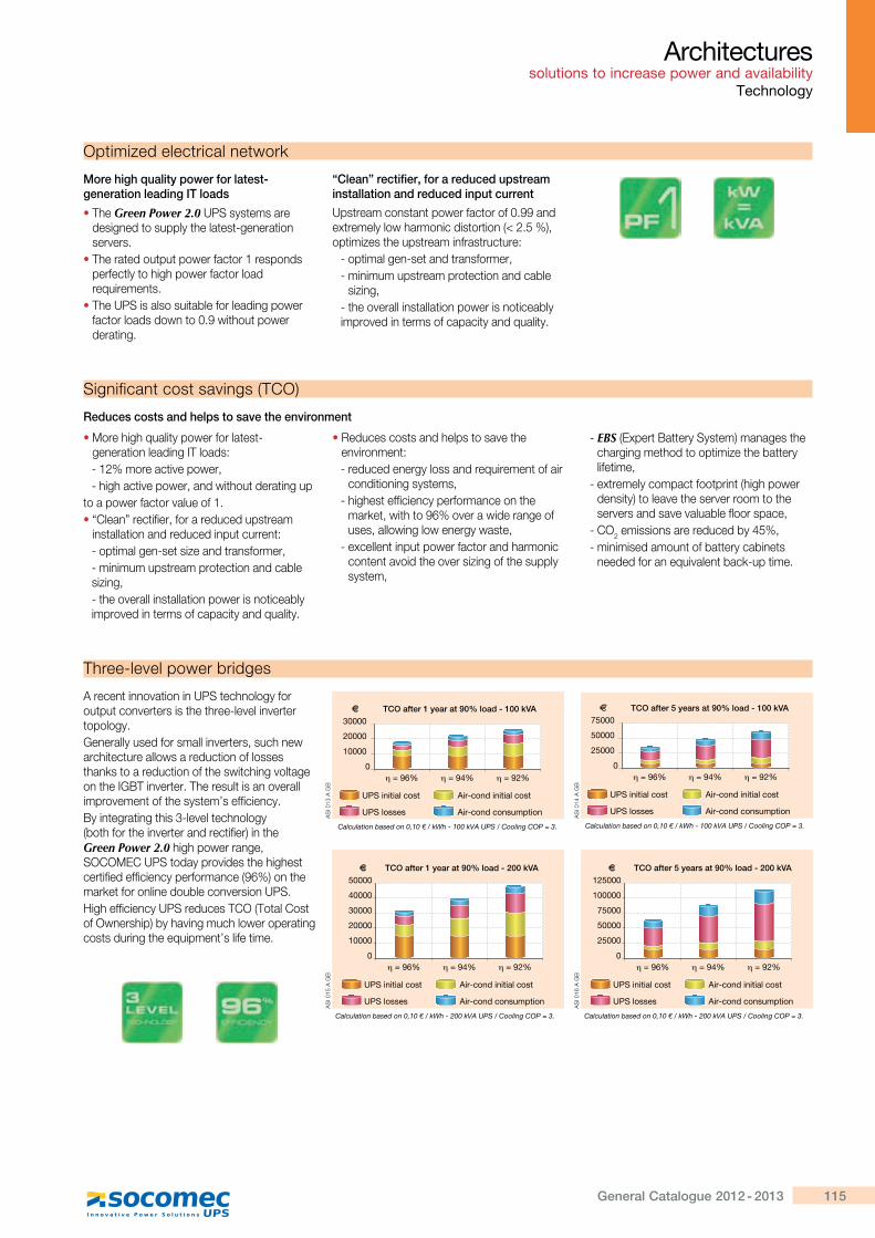
115General Catalogue 2012 - 2013
Architectures solutions to increase power and availability
Technology
Optimized electrical network
More high quality power for latest-generation leading IT loads
� The Green Power 2.0 UPS systems are designed to supply the latest-generation servers.
� The rated output power factor 1 responds perfectly to high power factor load requirements.
� The UPS is also suitable for leading power factor loads down to 0.9 without power derating.
“Clean” rectifier, for a reduced upstream installation and reduced input current
Upstream constant power factor of 0.99 and extremely low harmonic distortion (< 2.5 %), optimizes the upstream infrastructure:
- optimal gen-set and transformer,- minimum upstream protection and cable
sizing,- the overall installation power is noticeably improved in terms of capacity and quality.
Significant cost savings (TCO)
� More high quality power for latest-generation leading IT loads:- 12% more active power,- high active power, and without derating up
to a power factor value of 1.� “Clean” rectifier, for a reduced upstream
installation and reduced input current:- optimal gen-set size and transformer,- minimum upstream protection and cable sizing,- the overall installation power is noticeably improved in terms of capacity and quality.
� Reduces costs and helps to save the environment:- reduced energy loss and requirement of air
conditioning systems,- highest efficiency performance on the
market, with to 96% over a wide range of uses, allowing low energy waste,
- excellent input power factor and harmonic content avoid the over sizing of the supply system,
- EBS (Expert Battery System) manages the charging method to optimize the battery lifetime,
- extremely compact footprint (high power density) to leave the server room to the servers and save valuable floor space,
- CO2���������������������'\��- minimised amount of battery cabinets
needed for an equivalent back-up time.
Reduces costs and helps to save the environment
Three-level power bridges
A recent innovation in UPS technology for output converters is the three-level inverter topology.Generally used for small inverters, such new architecture allows a reduction of losses thanks to a reduction of the switching voltage on the IGBT inverter. The result is an overall improvement of the system’s efficiency.By integrating this 3-level technology (both for the inverter and rectifier) in the Green Power 2.0 high power range, SOCOMEC UPS today provides the highest certified efficiency performance (96%) on the market for online double conversion UPS.High efficiency UPS reduces TCO (Total Cost of Ownership) by having much lower operating costs during the equipment’s life time.
UPS initial cost
Calculation based on 0,10 € / kWh - 100 kVA UPS / Cooling COP = 3.
Air-cond initial cost
UPS losses Air-cond consumption
TCO after 1 year at 90% load - 100 kVA
0 = 96% = 94% = 92%
20000
10000
30000
UPS initial cost
Calculation based on 0,10 € / kWh - 200 kVA UPS / Cooling COP = 3.
Air-cond initial cost
UPS losses Air-cond consumption
TCO after 1 year at 90% load - 200 kVA
0 = 96% = 94% = 92%
40000
20000
10000
50000
30000
UPS initial cost
Calculation based on 0,10 € / kWh - 200 kVA UPS / Cooling COP = 3.
Air-cond initial cost
UPS losses Air-cond consumption
TCO after 5 years at 90% load - 200 kVA
0 = 96% = 94% = 92%
100000
50000
25000
125000
75000
UPS initial cost
Calculation based on 0,10 € / kWh - 100 kVA UPS / Cooling COP = 3.
Air-cond initial cost
UPS losses Air-cond consumption
TCO after 5 years at 90% load - 100 kVA
0 = 96% = 94% = 92%
50000
25000
75000
AS
I 013
A G
BA
SI 0
15 A
GB
AS
I 016
A G
B�
~?#
"'�
�|
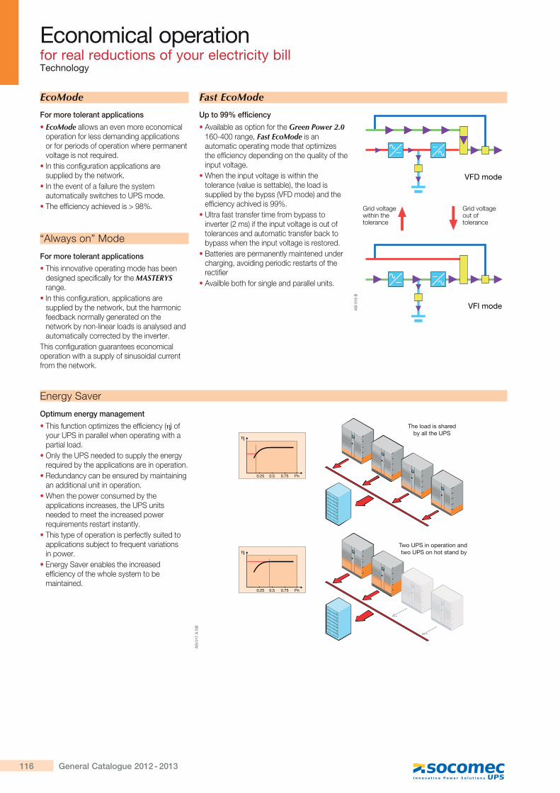
116 General Catalogue 2012 - 2013
For more tolerant applications
� EcoMode allows an even more economical operation for less demanding applications or for periods of operation where permanent voltage is not required.
� In this configuration applications are supplied by the network.
� In the event of a failure the system automatically switches to UPS mode.
� The efficiency achieved is > 98%.
Economical operation for real reductions of your electricity billTechnology
EcoMode
Optimum energy management
� This function optimizes the efficiency ( ) of your UPS in parallel when operating with a partial load.
� Only the UPS needed to supply the energy required by the applications are in operation.
� Redundancy can be ensured by maintaining an additional unit in operation.
� When the power consumed by the applications increases, the UPS units needed to meet the increased power requirements restart instantly.
� This type of operation is perfectly suited to applications subject to frequent variations in power.
� Energy Saver enables the increased efficiency of the whole system to be maintained.
Energy Saver
For more tolerant applications
� This innovative operating mode has been designed specifically for the MASTERYS range.
� In this configuration, applications are supplied by the network, but the harmonic feedback normally generated on the network by non-linear loads is analysed and automatically corrected by the inverter.
This configuration guarantees economical operation with a supply of sinusoidal current from the network.
“Always on” Mode
Up to 99% efficiency
� Available as option for the Green Power 2.0 160-400 range, Fast EcoMode is an automatic operating mode that optimizes the efficiency depending on the quality of the input voltage.
� When the input voltage is within the tolerance (value is settable), the load is supplied by the bypss (VFD mode) and the efficiency achived is 99%.
� Ultra fast transfer time from bypass to inverter (2 ms) if the input voltage is out of tolerances and automatic transfer back to bypass when the input voltage is restored.
� Batteries are permanently maintened under charging, avoiding periodic restarts of the rectifier
� Availble both for single and parallel units.
Fast EcoMode
VFD mode
VFI mode
Grid voltagewithin thetolerance
Grid voltageout oftolerance
η
0.25 0.5 0.75 Pn
η
0.25 0.5 0.75 Pn
The load is shared by all the UPS
Two UPS in operation and two UPS on hot stand by
AS
I 017
A G
B
AS
I 018
B
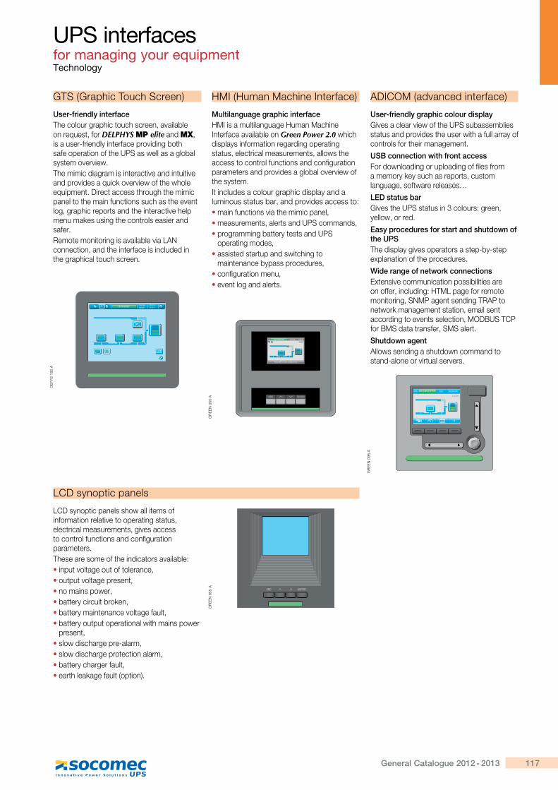
117General Catalogue 2012 - 2013
UPS interfaces for managing your equipmentTechnology
GTS (Graphic Touch Screen)
The colour graphic touch screen, available on request, for DELPHYS MP elite and MX, is a user-friendly interface providing both safe operation of the UPS as well as a global system overview.The mimic diagram is interactive and intuitive and provides a quick overview of the whole equipment. Direct access through the mimic panel to the main functions such as the event log, graphic reports and the interactive help menu makes using the controls easier and safer.Remote monitoring is available via LAN connection, and the interface is included in the graphical touch screen.
User-friendly interface
HMI (Human Machine Interface)
HMI is a multilanguage Human Machine Interface available on Green Power 2.0 which displays information regarding operating status, electrical measurements, allows the access to control functions and configuration parameters and provides a global overview of the system.It includes a colour graphic display and a luminous status bar, and provides access to:� main functions via the mimic panel,� measurements, alerts and UPS commands,� programming battery tests and UPS
operating modes,� assisted startup and switching to
maintenance bypass procedures,� configuration menu,� event log and alerts.
Multilanguage graphic interface
ADICOM (advanced interface)
User-friendly graphic colour displayGives a clear view of the UPS subassemblies status and provides the user with a full array of controls for their management.
USB connection with front accessFor downloading or uploading of files from a memory key such as reports, custom language, software releases…
LED status barGives the UPS status in 3 colours: green, yellow, or red.
Easy procedures for start and shutdown of the UPSThe display gives operators a step-by-step explanation of the procedures.
Wide range of network connectionsExtensive communication possibilities are on offer, including: HTML page for remote monitoring, SNMP agent sending TRAP to network management station, email sent according to events selection, MODBUS TCP for BMS data transfer, SMS alert.
Shutdown agentAllows sending a shutdown command to stand-alone or virtual servers.
DE
FYS
182
A
GR
EE
N 0
55 A
GR
EE
N 0
96 A
LCD synoptic panels
LCD synoptic panels show all items of information relative to operating status, electrical measurements, gives access to control functions and configuration parameters.These are some of the indicators available:� input voltage out of tolerance,� output voltage present,� no mains power,� battery circuit broken,� battery maintenance voltage fault,� battery output operational with mains power
present,� slow discharge pre-alarm,� slow discharge protection alarm,� battery charger fault,� earth leakage fault (option).
GR
EE
N 0
55 A
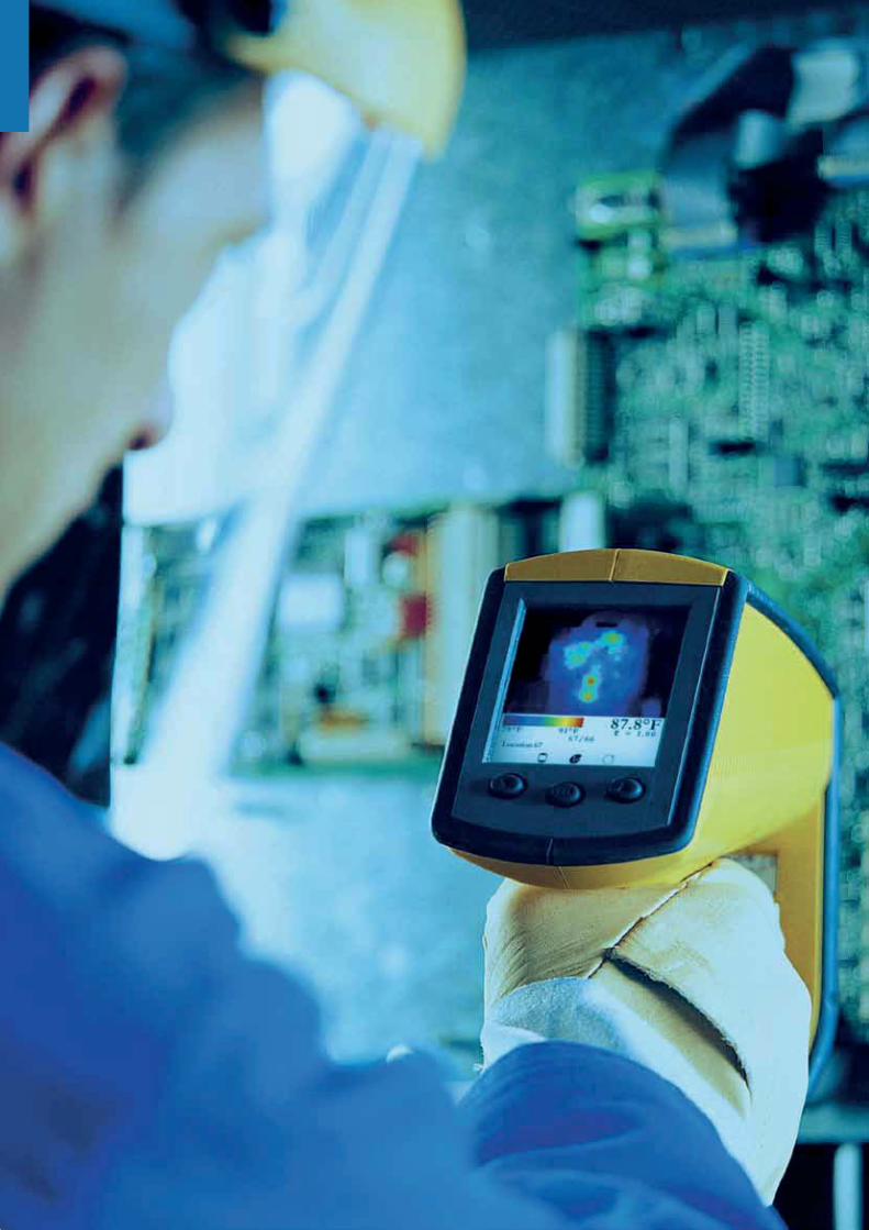
119General Catalogue 2012 - 2013
Commissioning Inspection and Maintenance
CIM maintenance contractsp.122
T.SERVICEp.123
CIM Thermop.124
CIM Rentp.126
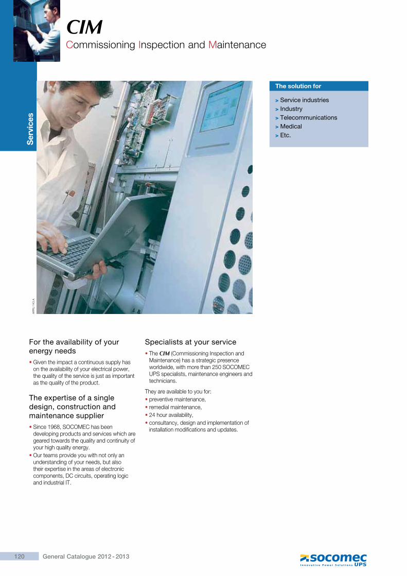
120 General Catalogue 2012 - 2013
CIMCommissioning Inspection and Maintenance
Ser
vice
s
The solution for
> Service industries> Industry> Telecommunications> Medical> Etc.
For the availability of your energy needs�Given the impact a continuous supply has
on the availability of your electrical power, the quality of the service is just as important as the quality of the product.
The expertise of a single design, construction and maintenance supplier�Since 1968, SOCOMEC has been
developing products and services which are geared towards the quality and continuity of your high quality energy.
�Our teams provide you with not only an understanding of your needs, but also their expertise in the areas of electronic components, DC circuits, operating logic and industrial IT.
Specialists at your service�The CIM (Commissioning Inspection and
Maintenance) has a strategic presence worldwide, with more than 250 SOCOMEC UPS specialists, maintenance engineers and technicians.
They are available to you for:�preventive maintenance,�remedial maintenance,�24 hour availability,�consultancy, design and implementation of
installation modifications and updates.
AP
PLI
143
A
121General Catalogue 2012 - 2013
CIM Commissioning Inspection and Maintenance
Understanding the need to maintain the availability of high quality energy, we place all the skills of our wide range of specialists at your disposal. Your entire equipment base is managed by the support service information system dedicated to monitoring it.
The guarantee of the best service Proximity
The various original parts and components that we stock guarantee that any faulty equipment can be rapidly brought back online, whilst maintaining its original performance and reliability.
Availability of parts
Our European and worldwide presence ensures that you will always have specialists close to your site, for a fast and efficient response.
The support service available to you (proximity, specialist personnel, stock of spare parts) means that we can contractually guarantee a response time, even 24-hour availability, compatible with your operating constraints.
Guaranteed response time
As a manufacturer, we are committed to protecting the environment and actively participate in the development of legislation and standards related to this issue.This guarantees that we will always respond to the demands of legislation concerning the disposal of used components and respect recycling procedures.
Respect for your environment
CA
RTE
021
A
AP
PLI
112
B
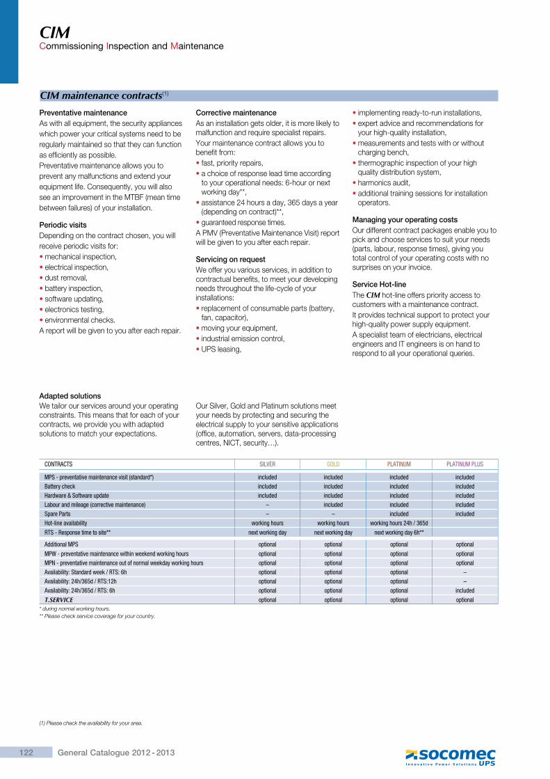
122 General Catalogue 2012 - 2013
CIM Commissioning Inspection and Maintenance
CIM maintenance contracts(1)
Preventative maintenanceAs with all equipment, the security applianceswhich power your critical systems need to beregularly maintained so that they can functionas efficiently as possible.Preventative maintenance allows you toprevent any malfunctions and extend yourequipment life. Consequently, you will alsosee an improvement in the MTBF (mean timebetween failures) of your installation.
Periodic visitsDepending on the contract chosen, you willreceive periodic visits for:�mechanical inspection,�electrical inspection,�dust removal,�battery inspection,�software updating,�electronics testing,�environmental checks.A report will be given to you after each repair.
Corrective maintenanceAs an installation gets older, it is more likely to malfunction and require specialist repairs.Your maintenance contract allows you to benefit from:�fast, priority repairs,�a choice of response lead time according
to your operational needs: 6-hour or next working day**,
�assistance 24 hours a day, 365 days a year (depending on contract)**,
�guaranteed response times.A PMV (Preventative Maintenance Visit) report will be given to you after each repair.
Servicing on requestWe offer you various services, in addition to contractual benefits, to meet your developing needs throughout the life-cycle of your installations:�replacement of consumable parts (battery,
fan, capacitor),�moving your equipment,�industrial emission control,�UPS leasing,
�implementing ready-to-run installations,�expert advice and recommendations for
your high-quality installation,�measurements and tests with or without
charging bench,�thermographic inspection of your high
quality distribution system,�harmonics audit,�additional training sessions for installation
operators.
Managing your operating costsOur different contract packages enable you to pick and choose services to suit your needs (parts, labour, response times), giving you total control of your operating costs with no surprises on your invoice.
Service Hot-lineThe CIM hot-line offers priority access to customers with a maintenance contract.It provides technical support to protect your high-quality power supply equipment.A specialist team of electricians, electrical engineers and IT engineers is on hand to respond to all your operational queries.
We tailor our services around your operating constraints. This means that for each of your contracts, we provide you with adapted solutions to match your expectations.
Our Silver, Gold and Platinum solutions meet your needs by protecting and securing the electrical supply to your sensitive applications (office, automation, servers, data-processing centres, NICT, security…).
Adapted solutions
CONTRACTS SILVER GOLD PLATINUM PLATINUM PLUS
MPS - preventative maintenance visit (standard*) included included included includedBattery check included included included includedHardware & Software update included included included includedLabour and mileage (corrective maintenance) – included included includedSpare Parts – – included includedHot-line availability working hours working hours working hours 24h / 365d
RTS - Response time to site** next working day next working day next working day 6h**
Additional MPS optional optional optional optional
MPW - preventative maintenance within weekend working hours optional optional optional optionalMPN - preventative maintenance out of normal weekday working hours optional optional optional optionalAvailability: Standard week / RTS: 6h optional optional optional –Availability: 24h/365d / RTS:12h optional optional optional –Availability: 24h/365d / RTS: 6h optional optional optional included
T.SERVICE optional optional optional optional* during normal working hours.** Please check service coverage for your country.
(1) Please check the availability for your area.
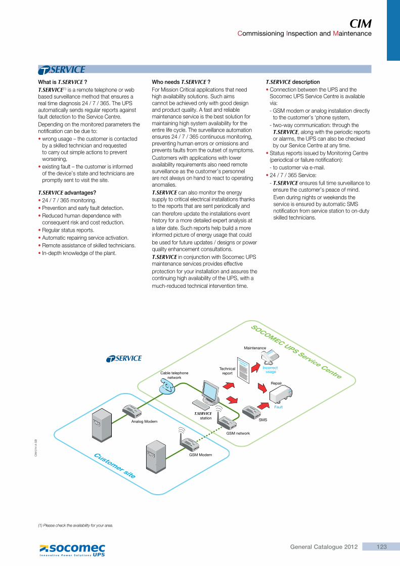
123General Catalogue 2012
CIM Commissioning Inspection and Maintenance
What is T.SERVICE ?T.SERVICE(1) is a remote telephone or web based surveillance method that ensures a real time diagnosis 24 / 7 / 365. The UPS automatically sends regular reports against fault detection to the Service Centre.Depending on the monitored parameters the notification can be due to:�wrong usage – the customer is contacted
by a skilled technician and requested to carry out simple actions to prevent worsening,
�existing fault – the customer is informed of the device’s state and technicians are promptly sent to visit the site.
T.SERVICE advantages?�24 / 7 / 365 monitoring.�Prevention and early fault detection.�Reduced human dependence with
consequent risk and cost reduction.�Regular status reports.�Automatic repairing service activation.�Remote assistance of skilled technicians.�In-depth knowledge of the plant.
Who needs T.SERVICE ?For Mission Critical applications that need high availability solutions. Such aims cannot be achieved only with good design and product quality. A fast and reliable maintenance service is the best solution for maintaining high system availability for the entire life cycle. The surveillance automation ensures 24 / 7 / 365 continuous monitoring, preventing human errors or omissions and prevents faults from the outset of symptoms.Customers with applications with lower availability requirements also need remote surveillance as the customer’s personnel are not always on hand to react to operating anomalies.T.SERVICE can also monitor the energy supply to critical electrical installations thanks to the reports that are sent periodically andcan therefore update the installations event history for a more detailed expert analysis ata later date. Such reports help build a more informed picture of energy usage that couldbe used for future updates / designs or power quality enhancement consultations.T.SERVICE in conjunction with Socomec UPS maintenance services provides effectiveprotection for your installation and assures the continuing high availability of the UPS, with amuch-reduced technical intervention time.
T.SERVICE description�Connection between the UPS and the
Socomec UPS Service Centre is available via:- GSM modem or analog installation directly
to the customer’s ‘phone system,- two-way communication: through the
T.SERVICE, along with the periodic reports or alarms, the UPS can also be checked by our Service Centre at any time.
�Status reports issued by Monitoring Centre (periodical or failure notification):- to customer via e-mail.
�24 / 7 / 365 Service:- T.SERVICE ensures full time surveillance to
ensure the customer’s peace of mind.Even during nights or weekends the service is ensured by automatic SMS notification from service station to on-duty skilled technicians.
DIAGNOSTIC REPORT
TechnicalreportCable telephone
network
SOCOMEC UPS Service Centre
SMS
Maintenance
Incorrectusage
Fault
Repair
Analog Modem
GSM Modem
GSM network
Customer site
T.SERVICEstation
CIM
014
A G
B
(1) Please check the availability for your area.
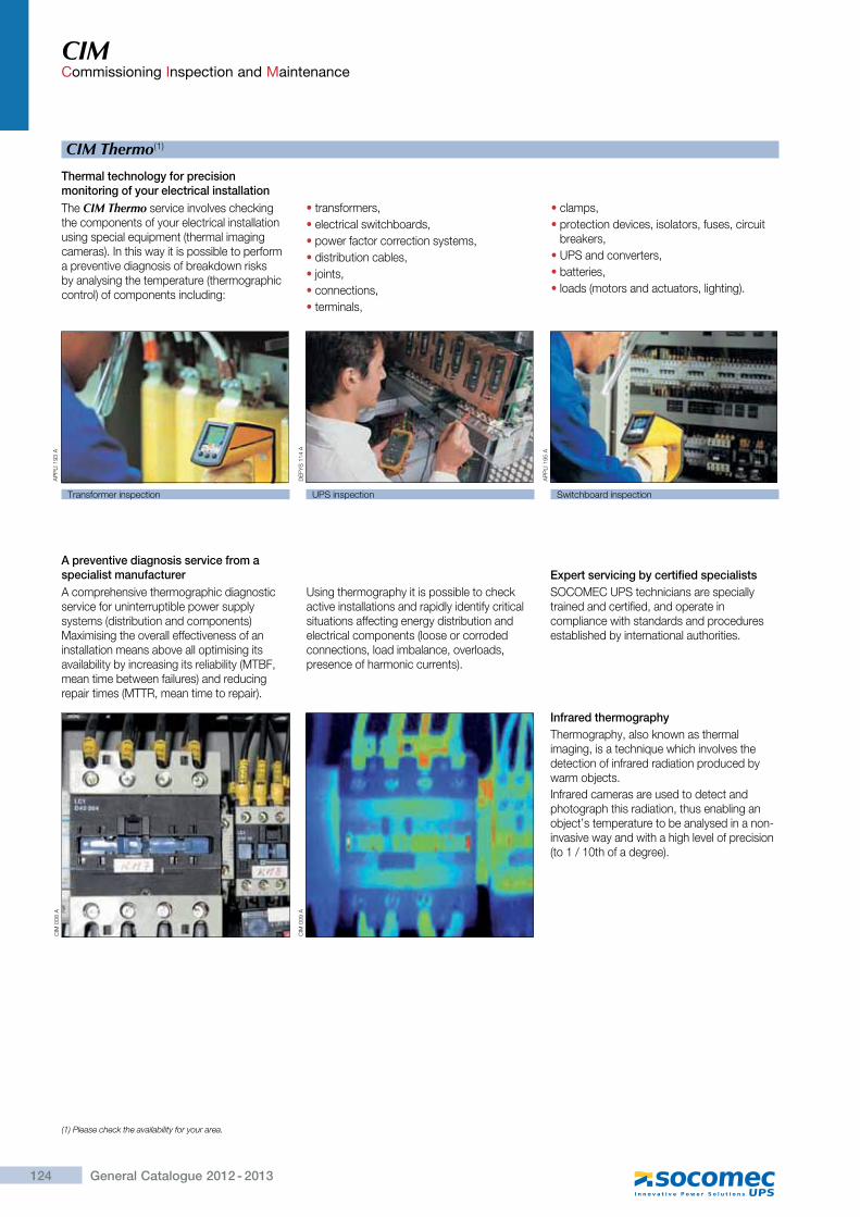
124 General Catalogue 2012 - 2013
CIM Commissioning Inspection and Maintenance
CIM Thermo(1)
The CIM Thermo service involves checking the components of your electrical installation using special equipment (thermal imaging cameras). In this way it is possible to perform a preventive diagnosis of breakdown risks by analysing the temperature (thermographic control) of components including:
�transformers,�electrical switchboards,�power factor correction systems,�distribution cables,�joints,�connections,�terminals,
�clamps,�protection devices, isolators, fuses, circuit
breakers,�UPS and converters,�batteries,�loads (motors and actuators, lighting).
CIM
008
A
CIM
009
A
AP
PLI
193
A
DE
FYS
114
A
AP
PLI
195
A
Transformer inspection UPS inspection Switchboard inspection
Thermal technology for precision monitoring of your electrical installation
A comprehensive thermographic diagnostic service for uninterruptible power supply systems (distribution and components) Maximising the overall effectiveness of an installation means above all optimising its availability by increasing its reliability (MTBF, mean time between failures) and reducing repair times (MTTR, mean time to repair).
Using thermography it is possible to check active installations and rapidly identify critical situations affecting energy distribution and electrical components (loose or corroded connections, load imbalance, overloads, presence of harmonic currents).
A preventive diagnosis service from a specialist manufacturer
SOCOMEC UPS technicians are specially trained and certified, and operate in compliance with standards and procedures established by international authorities.
Expert servicing by certified specialists
Thermography, also known as thermal imaging, is a technique which involves the detection of infrared radiation produced by warm objects.Infrared cameras are used to detect and photograph this radiation, thus enabling an object’s temperature to be analysed in a non-invasive way and with a high level of precision (to 1 / 10th of a degree).
Infrared thermography
(1) Please check the availability for your area.
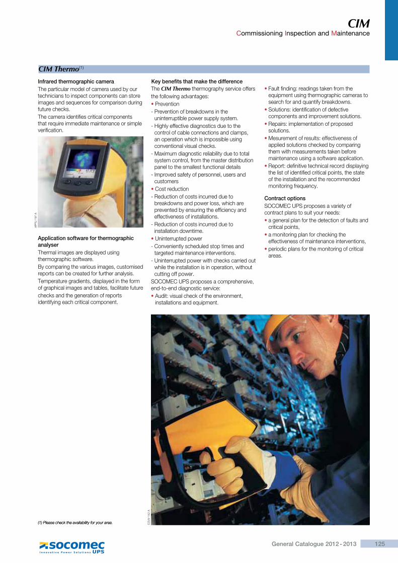
125General Catalogue 2012 - 2013
CIM Commissioning Inspection and Maintenance
(1) Please check the availability for your area.
CIM Thermo(1)
Infrared thermographic cameraThe particular model of camera used by our technicians to inspect components can store images and sequences for comparison during future checks.The camera identifies critical components that require immediate maintenance or simple verification.
Application software for thermographic analyserThermal images are displayed using thermographic software.By comparing the various images, customised reports can be created for further analysis.Temperature gradients, displayed in the form of graphical images and tables, facilitate futurechecks and the generation of reports identifying each critical component.
Key benefits that make the difference
(1) Please check the availability for your area.
AP
PLI
197
A
CO
UV
142
A
The CIM Thermo thermography service offersthe following advantages:�Prevention- Prevention of breakdowns in the
uninterruptible power supply system.- Highly effective diagnostics due to the
control of cable connections and clamps, an operation which is impossible using conventional visual checks.
- Maximum diagnostic reliability due to total system control, from the master distribution panel to the smallest functional details
- Improved safety of personnel, users and customers
�Cost reduction- Reduction of costs incurred due to
breakdowns and power loss, which are prevented by ensuring the efficiency and effectiveness of installations.
- Reduction of costs incurred due to installation downtime.
�Uninterrupted power- Conveniently scheduled stop times and
targeted maintenance interventions.- Uninterrupted power with checks carried out
while the installation is in operation, without cutting off power.
SOCOMEC UPS proposes a comprehensive, end-to-end diagnostic service:�Audit: visual check of the environment,
installations and equipment.
�Fault finding: readings taken from the equipment using thermographic cameras to search for and quantify breakdowns.
�Solutions: identification of defective components and improvement solutions.
�Repairs: implementation of proposed solutions.
�Mesurement of results: effectiveness of applied solutions checked by comparing them with measurements taken before maintenance using a software application.
�Report: definitive technical record displaying the list of identified critical points, the state of the installation and the recommended monitoring frequency.
Contract optionsSOCOMEC UPS proposes a variety of contract plans to suit your needs:�a general plan for the detection of faults and
critical points,�a monitoring plan for checking the
effectiveness of maintenance interventions,�periodic plans for the monitoring of critical
areas.
126 General Catalogue 2012 - 2013
CIM Commissioning Inspection and Maintenance
CIM Rent(1)
UPS leasing, your high-quality temporary power solutionWhen you require high-quality uninterrupted electrical energy over a limited period (weeks or months), leasing is the most economical answer for your short-term needs.Leasing enables you to draw on the global expertise of SOCOMEC, which not only assures the availability of the UPS system, but also provides an all-in-one service to guarantee you a clean and uninterrupted energy supply.The user chooses the required power rating and back-up time, as well as the lease term, which can be extended according to need.No need to waste further time and resources managing your UPS system, the CIM (Consulting, Inspection and Maintenance) service will take care of everything, from operation and maintenance to removal at the end of the contract.
Applications�Computing.�Event-based technical platforms.�Sound and lighting consoles.�Industrial processes.
Events�Temporary works phase.�Unforeseen disaster.�Displays and shows.�When investment isn’t possible.
Requirements specificationsTo set up the lease, simply specify:�the required power rating (several kVA to
several hundred kVA),�the redundancy level (single / parallel),�the required back-up time,�the lease term,�the site / address of the installation,�any additional options,�associated services.
Standard services included in the lease�Consulting on environmental aspects:
ventilation, positioning, electrical distribution and protection ratings.
�Transport.�Commissioning.�Telephone hot-line (freephone).�Next-day repair service.�UPS decommissioning and removal.
Additional services�On-site maintenance.�Installation and cabling.�Maintenance response within 6-hour or next
working day.�24-hour on-call maintenance.�Training for operation personnel.
Benefits�Reduced investment: solution supplied with
a reduced operating budget, without the obligation to purchase.
�Quick: rapid delivery and commissioning.�Simple: leasing, transport, commissioning
and return of hardware included.�Responsive: priority response from the
SOCOMEC After-Sales Service in the event of breakdowns.
�Compliance with standards: guaranteed by SOCOMEC.
�Tax relief: rental fees can be posted in an operating budget.
AP
PLI
_135
_A
Our specific leasing packages
Long-term leasingFor lease periods of several weeks to several months, hardware can be delivered ready-to-run.SOCOMEC is able to provide consulting on environmental aspects (ventilation and room layout, cable sizing and protective devices, etc). SOCOMEC can install the UPS in your dedicated equipment room prior to commissioning it. This latter process, which is performed in compliance with applicable safety standards and regulations, ensures the efficient operation of the system.The installed system solution gives you the opportunity of selecting the:�power rating,�back-up time,�optional extras,�associated services.
Contract flexibilityThe contract may be modified:�there is no maximum rental period,�the lease term can be increased while the
contract is ongoing.
AP
PLI
_205
_A
(1) Please check the availability for your area.
127General Catalogue 2012 - 2013
Notes
128 General Catalogue 2012 - 2013
Notes

2012
2013
MAX POWER(parallel)250 500 1000
-
-
-
-
-
-
-
-
-
-
1+1 redundant
1+1 redundant
120 kVA
360 kVA
-
1+1 redundant
1+1 redundant
360 kVA
2400 kVA
480 kVA
1200 kVA
250 - 900 5400 kVA
-
200 - 1000 2400 kVA
INFRASTRUCTURE
TRANSPORT UTILITIESTELECOM NETWORK
MASTERYS IP+ �p.00 MASTERYS BC�p.32 MASTERYS BC�p.32
MODULYS TC�p.30
MASTERYS IP+�p.44DELPHYS MP�p.46DELPHYS MX�p.48GREEN POWER 2.0�p.40
MASTERYS BC�p.34GREEN POWER 2.0�p.40GREEN POWER 2.0�p.42
MASTERYS BC�p.34GREEN POWER 2.0�p.40GREEN POWER 2.0�p.42
SMART POWERPORT�p.56
IT SWITCH�p.62 IT SWITCH�p.62STATYS�p.60
STATYS�p.60
SHARYS IP�p.68 SHARYS MICRO�p.72SHARYS MINI�p.72SHARYS ELITE �p.74
Production: SOCOMEC Communication DepartmentGraphics: SOCOMECPhotography: Martin Bernhart and SOCOMECPrinting: PVA, Druck und Medien-Dienstleistungen GmbH
Industriestraße 15, D-76829 Landau/Pfalz
To help protect the environment, this document has been printed on PEFC paper (Programme for the Endorsement of Forest Certifi cation).

VALID FOR FRANCE VALID FOR ITALY
ISO 9001FM 28237
ISO14001EMS 553476
www.socomec.com
YOUR DISTRIBUTOR
To h
elp
prot
ect t
he e
nviro
nmen
t, th
is d
ocum
ent h
as b
een
prin
ted
on P
EFC
pap
er (P
rogr
amm
e fo
r the
End
orse
men
t of F
ores
t Cer
tific
atio
n)
Non contractual document. © 2012, Socomec SA. All rights reserved.
HEAD OFFICE
SOCOMEC GROUPS.A. SOCOMEC capital 11 149 200 € - R.C.S. Strasbourg B 548 500 149 B.P. 60010 - 1, rue de Westhouse - F-67235 Benfeld Cedex
SOCOMEC UPS Strasbourg11, route de Strasbourg - B.P. 10050 - F-67235 Huttenheim Cedex- FRANCE Tel. +33 (0)3 88 57 45 45 - Fax +33 (0)3 88 74 07 90 [email protected]
SOCOMEC UPS Isola VicentinaVia Sila, 1/3 - I - 36033 Isola Vicentina (VI) - ITALY Tel. +39 0444 598611 - Fax +39 0444 598622 [email protected]
SALES, MARKETING AND SERVICE MANAGEMENT
SOCOMEC UPS Paris95, rue Pierre Grange F-94132 Fontenay-sous-Bois Cedex - FRANCE Tel. +33 (0)1 45 14 63 90 - Fax +33 (0)1 48 77 31 12 [email protected]
Socomec UPS worldwide
IN WESTERN EUROPE
BELGIUMSchaatsstraat, 30 rue du Patinage B - 1190 Bruxelles Tel. +32 (0)2 340 02 34 [email protected]
FRANCE95, rue Pierre Grange F - 94132 Fontenay-sous-Bois Cedex Tel. +33 (0)1 45 14 63 90 [email protected]
GERMANYHeppenheimer Straße 57 D - 68309 Mannheim Tel. +49 (0) 621 71 68 40 [email protected]
ITALYVia Leone Tolstoi, 73 - Zivido 20098 San Giuliano Milanese (MI) Tel. +39 02 98 242 942 [email protected]
PORTUGALNúcleo Empresarial de Mafra II Av. Dr. Francisco Sá Carneiro, Fracção N 2640-486 Mafra Tel. +351 261 812 599 [email protected]
SPAINC/Nord, 22 Pol. Ind. Buvisa E - 08329 Teià (Barcelona) Tel. +34 935 407 575 [email protected]
THE NETHERLANDSDuwboot 13 NL - 3991 CD Houten Tel. +31 (0)30 760 0911 [email protected]
UNITED KINGDOMUnits 7A-9A Lakeside Business Park Broadway Lane - South Cerney Cirencester - GL7 5XL Tel. +44 (0)1285 863300 [email protected]
OTHER COUNTRIESTel. +34 935 407 575 [email protected]
IN EASTERN EUROPE, MIDDLE EAST, AFRICA
UNITED ARAB EMIRATESLIU-E17 DAFZA 371355 Dubai airport free zone Dubai (United Arab Emirates) Tel.: +971 (0) 4 29 98 441 [email protected]
POLANDul. Mickiewicza 63 01-625 Warszawa Tel. +48 22 825 73 60 [email protected]
ROMANIAHeliade Intre Vii Street no.8, 2 District 023383 Bucharest Tel. +40 21 319 36 88 ( 89, 81, 82) [email protected]
RUSSIA4th Street 8 Marta, 6A, 405 125167 - Moscow Tel. +7 495 775 19 85 [email protected]
SLOVENIASavlje 89 SI - 1000 Ljubljana Tel. +386 1 5807 860 [email protected]
TURKEYMasuklar Yokusu No:57/2 34357 Besiktas Istanbul Tel. +90 212 2580810 [email protected]
OTHER COUNTRIESTel. +39 0444 598 611 [email protected]
IN ASIA PACIFIC
AUSTRALIAUnit 3, 2 Eden Park Drive (Rydecorp) Macquarie Park NSW 2113 Tel. +61 2 9325 3900 [email protected]
CHINAUniversal Business Park B33, Floor 3, 10 Jiuxianqiao Lu, Chaoyang, Beijing 100016 P.R., China Tel. +86 10 59756108 [email protected]
INDIAB1, IInd Floor, Thiru-Vi-Ka-Industrial Estate Guindy Chennai – 600 032 Tel. +91 44 3921 5400 [email protected]
MALAYSIA31 Jalan SS 25/41- Mayang Industrial Park 47301 Petaling Jaya.- Selangor, Malaysia Tel. +603 7804 1153 [email protected]
SINGAPORE 31 Ubi Road 1 #01-00 (Lobby B) Aztech Building Singapore 408694 Tel. +65 6506 7600 [email protected]
THAILANDNo.9 Soi Vibhavadirangsit 42 Vibhavadirangsit Rd, Ladyao Chatujak Bangkok 10900 Tel. +66 2 941-1644-7 [email protected]
VIETNAM539/23 Luy Ban Bich St., Phu Thanh Ward, Tan Phu Dist Ho Chi Minh City Tel. +84-839734.990 [email protected]
ASIA PACIFIC HEAD OFFICETel. +65 6507 [email protected]
IN AMERICA
LATIN AMERICAN COUNTRIESTel. +34 935 407 575 [email protected]
Réf
. DC
G 8
4083