Embed Size (px)
Citation preview

While this information is presented in good faith and believed to be accurate, A-D Technologies does not, however, guarantee satisfactory results from reliance on such information due to the many variables attendant with every situation. Persons or parties utilizing this publication are solely responsible for the proper selection, installation, operation, maintenance and utilization of all products. Nothing contained herein is to be construed as a warranty or guarantee, express or implied, regarding the performance, merchantability, fitness, or any other matter with respect to the products, nor as a recommendation to use any product in conflict with the intellectual property rights of any third party. A-D Technologies reserves the right, without notice, to alter or improve the design or specifications of the products described herein. [All sales are pursuant to A-D Technologies’ terms and conditions of sale] Reproduction of this document, in part or in whole, is permitted solely for the purpose of distribution to other persons within your organization or contractors doing work for your company. All other distribution will require written consent from A-D Technologies.
Technical Bulletin: DCEB-10001 Issue: A
Date: April 1, 2010 Page 1 of 22
U N C O N T R O L L E D C O P Y
TECHNICAL BULLETIN
FUTUREPATH® FLEX INSTALLATION RECOMMENDATIONS
CONTENTS: 1.0 General Information 2.0 Installation Recommendations 3.0 Splicing Recommendations 4.0 Contact Information

Technical Bulletin: DCEB-10001 Issue: A
Date: April 1, 2010 Page 2 of 22
U N C O N T R O L L E D C O P Y
1.0 GENERAL INFORMATION
1.1 FuturePath® Flex is a configuration of MicroDucts designed to provide installation pathways for MicroFiber and fiber optic drop cable, and is designed for buried and MicroTrenching applications. MicroTrench Technology provides limited disruption during excavation when installing fiber optic pathways, especially for FTTx implementation. A MicroTrench may be a specified narrow saw cut or could be defined as a shallow trench where depth limitations minimize placing options. Available as a 2-way, 4-way, or 6-way structure, FuturePath® Flex can be adapted for nearly any FTTx installation (Figure 1).
Figure 1
1.2 FuturePath® Flex was developed by A-D Technologies for use as a
backbone pathway or last mile deployment of FTTx networks. It can be direct buried where the only option for placing a fiber optic pathway is a narrow slit trench excavation, or it can be used in traditional trenching operations.

Technical Bulletin: DCEB-10001 Issue: A
Date: April 1, 2010 Page 3 of 22
U N C O N T R O L L E D C O P Y
Horizontal Directional Drilling (HDD), plow installations, or pulling into existing conduit can also be accomplished. MicroTrenching can be an economical alternative when placing an FTTx pathway; especially where limited space is available for excavation, and restoral to original conditions needs to be completed in a timely fashion. Municipalities as well as property owners may also require MicroTrenching as a condition for installation. MicroTrenching may provide additional routes for supplying customers with the most up-to-date technologies, and cause designers of telecommunications facilities to consider MicroTrenching the primary choice in many situations. FuturePath® Flex provides a highly flexible application for installation of multiple MicroDucts, providing easy access to the ducts and fiber, and requires minimal accessories and no special tools for a successful installation. Routing branch pathways or branch-offs does not require the use of branching closures, although they can be used if desired for additional mechanical protection. FuturePath® Flex can be used for many other applications besides a fiber network build. It can be used for IMSA (International Municipal Signal Association) low voltage street light signal wiring, signal loop wiring, coax, and various other low voltage copper communication wire and DOT applications.
1.3 Equipment manufacturers have developed an array of trenchers and saws to
facilitate the use of MicroTrenching. This Technical Bulletin does not recommend any equipment type, but serves as an overall guideline to the MicroTrenching and installation for FuturePath® Flex MicroDucts. Photo references to equipment are used as examples only, and not an endorsement of any type or manufacturer. Users of FuturePath® must decide on equipment choices, but should consider trenching requirements and equipment limitations in the decision. Installers should consider design requirements such as trench width and depth before employing any equipment type.
1.4 FuturePath® Flex is a MicroDuct bundle that is arrayed in a flat
configuration, and may be inserted into a narrow slit trench when standard FuturePath® or innerduct installation is not be possible. It may also be placed in conjunction with other duct structures to increase route capacity and maximize installation expenditures (Figures 2-3).

Technical Bulletin: DCEB-10001 Issue: A
Date: April 1, 2010 Page 4 of 22
U N C O N T R O L L E D C O P Y
Figure 2 Figure 3
1.5 When a shipment of FuturePath® Flex is received, it is important to inspect
the duct and reel for any shipping damage. A-D Technologies uses third-party shipping companies, whose operators may not be as familiar with reel handling as an A-D Technologies employee or field construction forces. When using a forklift for unloading FuturePath® Flex from the truck, lift the reel from the side placing the forks under the reel flanges. DO NOT lift the reel with the forks under the FuturePath® Flex (Figure 4).
Figure 4
When using a boom truck to unload the FuturePath® Flex, place a bar though
the reel arbor then attach a chain to the bar. DO NOT wrap a chain around the FuturePath® Flex in order to lift the reel.
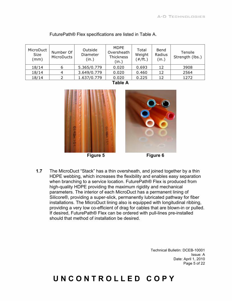
1.6 FuturePath® Flex MicroDucts are thick walled and tangentially joined with
bridges in a side-by-side flat bundle (Figure 5). The bridges allow the folding of the bundle and enable the duct structure to conform to multiple shapes (Figure 6).
Technical Bulletin: DCEB-10001 Issue: A
Date: April 1, 2010 Page 5 of 22
U N C O N T R O L L E D C O P Y
FuturePath® Flex specifications are listed in Table A.
Table A
Figure 5 Figure 6
1.7 The MicroDuct “Stack” has a thin oversheath, and joined together by a thin
HDPE webbing, which increases the flexibility and enables easy separation when branching to a service location. FuturePath® Flex is produced from high-quality HDPE providing the maximum rigidity and mechanical parameters. The interior of each MicroDuct has a permanent lining of Silicore®, providing a super-slick, permanently lubricated pathway for fiber installations. The MicroDuct lining also is equipped with longitudinal ribbing, providing a very low co-efficient of drag for cables that are blown-in or pulled. If desired, FuturePath® Flex can be ordered with pull-lines pre-installed should that method of installation be desired.
MicroDuct Size
(mm)
Number Of MicroDucts
Outside Diameter
(in.)
MDPE Oversheath Thickness
(in.)
Total Weight (#/ft.)
Bend Radius (in.)
Tensile Strength (lbs.)
18/14 6 5.365/0.779 0.020 0.693 12 3908 18/14 4 3.649/0.779 0.020 0.460 12 2564 18/14 2 1.637/0.779 0.020 0.225 12 1272

Technical Bulletin: DCEB-10001 Issue: A
Date: April 1, 2010 Page 6 of 22
U N C O N T R O L L E D C O P Y
Designed primarily for small cables and drops, the flat configuration allows easy separation and routing of the MicroDuct pathways, while providing excellent protection for the fibers within (Figure 7).
Figure 7
2.0 INSTALLATION RECOMMENDATIONS
2.1 FuturePath® Flex can be used for direct-bury applications as well as for use in Horizontal Directional Drilling implementation (for HDD, see section 2.10). For successful FuturePath® Flex installations, it is recommended that trenches be constructed in such a way as to provide a consistent, high-quality surround for the FuturePath®. The trench bottom should be as level and flat as possible, and free of rocks or other protuberances that could distort the HDPE (High Density Polyethylene) over time (Figure 8). For rocky soil, a 2-inch layer of sand is recommended prior to laying the FuturePath® into the trench. It is recommended to tamp the base layer of soil to provide a flat, straight path for the FuturePath® Flex After placement of the duct (Figure 9), backfill with sand and cover with a minimal two-inch layer before backfilling the trench with native soil. Should additional pathways be required, FuturePath® Flex can be stacked one upon another, or side-by-side. Ordering it with different color stripes can aid in easy identification should this be necessary. When placing into a trench, pull the MicroDucts tight at intervals to minimize bending or “snaking” of the product.

Technical Bulletin: DCEB-10001 Issue: A
Date: April 1, 2010 Page 7 of 22
U N C O N T R O L L E D C O P Y
Figure 8 Figure 9
Maintain the minimum bend radius (Table A) for all FuturePath® Flex
installations. If possible, turn the FuturePath® Flex at 90-degrees or standing upright when making a turn. This makes it easier to change directions and allows for a tighter bend radius (Figure 10).
Figure 10
2.2 Backfilling with a finer grade of material such as sand will cause the FuturePath® Flat to gain additional strength because the voids between the ducts will be more easily filled. When compacted, the fine grain fill will provide superior strength to the MicroDucts and allow maximum compaction of the fill. The fine-grain backfill will deliver insulating properties around the FuturePath® prior to hot asphalt applications (Figure 11). See Section 2.4 and 2.6 for cold climate applications. As in all MicroDuct installations, it is recommended to maintain as straight of a route as possible (Figure 12).

Technical Bulletin: DCEB-10001 Issue: A
Date: April 1, 2010 Page 8 of 22
U N C O N T R O L L E D C O P Y
Figure 11 Figure 12
2.3 While FuturePath® Flex can be installed into a trench, saw cut, underground
conduit, or Horizontally Directionally Drilled, this work should be performed only by individuals trained in the operation of the machinery and procedures for placing FuturePath® Flex, as outlined by this document. Equipment should be verified that it is in proper working order before beginning any installation.
2.4 Frost heave occurs when moisture-retaining soils are exposed to sub-
freezing temperatures for a prolonged period. As freezing extends deeper into the soil, retained moisture expands. Since the moisture cannot expand downwards, and lateral expansion is somewhat contained, it follows the path of least resistance, which is generally upwards. Any object embedded in soil subject to these conditions will also be lifted. This includes buried conduit. Factors determining the degree of lift include the amount of retained water, depth of any insulating snow cover, the sub-zero temperature levels, and the duration of exposure. During a typical northern winter, accompanied by normal snowfall (which acts as an insulating blanket) only a very small percentage of surface area actually freezes. When the snow blanket is absent, plowed away (as in roads, walkways), or prevented from accumulating (under bridges or other protected areas), the ground may freeze and subsequent frost heave can be severe. To help minimize frost heave after installing the FuturePath® Flex, ensure that restoration of

Technical Bulletin: DCEB-10001 Issue: A
Date: April 1, 2010 Page 9 of 22
U N C O N T R O L L E D C O P Y
walkways or road surfaces is complete and properly compacted so as to avoid surface water penetration into the area around the duct. It is suggested that soil used to backfill be of a low moisture level initially in order to minimize this effect in colder climates. Due to the behavior of an object when subjected to frost heave, the object (in this case, the duct structure) continues to be pushed upward as each freeze cycle causes soil to migrate below the duct. Eventually, these cycles can break up the surface restoration (potholes), and even allow the duct to become exposed. Proper restoration with asphalt, cement, or grout will help limit moisture migration into the softer soil layers, minimizing frost heave.
2.5 FuturePath® Flex can be plowed into soils if desired (Figures 13-14). Soft or
sandy soils will be best for this application, as rocky soil may interfere with the installation.
Figure 13
Figure 14

Technical Bulletin: DCEB-10001 Issue: A
Date: April 1, 2010 Page 10 of 22
U N C O N T R O L L E D C O P Y
2.6 While most trenching, HDD, and conduit installations are fairly common practices, saw cutting or slit trench applications are relatively new procedures. This section outlines some points to consider when placing FuturePath® Flex into saw cuts. Cutting equipment should be selected based upon the requirements of the product placed and the job parameters. For instance, if vehicular traffic is to travel over the duct system, it is recommended that a minimum cover 6” be placed. Governing bodies may have certain requirements that would override these recommendations. Where extreme temperatures are involved, and where the soil may be subject to ice shifting or frost heave, it is suggested that additional depth of cover be placed. Cutting a path 3” wide and 24” deep would provide room for a 2” bed layer of fine composite, 6” for the FuturePath® Flex to stand upright, and 16” of cover. In areas not typically affected by ice shifting or frost heave, 6”-8” of cover is adequate (Figure 15).
Figure 15
2.7 Cutting equipment used for MicroTrenching should be capable of delivering a cleanly cut trench through the material being displaced (Figure 16). Blades should be sized to provide the desired width and depth so adequate cover can be obtained. Do not stand directly in front of or behind the cutting blades, as the blades can throw debris. Trench size depends upon the actual dimensions of the product being installed, but it is recommended to cut a minimum of 2” wide by 16” deep pathway for the 6-way FuturePath® Flex. If the pathway will be exposed to vehicular traffic, careful consideration should be given to the depth of cover required, as the road bed construction will need to be restored to original values. Check with local authorities to ascertain and verify requirements.

Technical Bulletin: DCEB-10001 Issue: A
Date: April 1, 2010 Page 11 of 22
U N C O N T R O L L E D C O P Y
Figure 16
It is recommended that all saw cuts should be performed in lines, keeping as
straight as possible, and curved routes should staged on gradual 450 cuts (Figures 17-18). Where tighter turns are required, take care to ensure that the minimum bend radius of the duct is maintained. When possible, perform cuts in long straight lines, which provide a clean look after restoral (Figure 19).
Figure 17 Figure 18

Technical Bulletin: DCEB-10001 Issue: A
Date: April 1, 2010 Page 12 of 22
U N C O N T R O L L E D C O P Y
Figure 19
2.8 Transitioning from a conduit or borehole is facilitated by the flexible design of
the FuturePath® Flex. Placing the duct into the saw cut is fast and requires no special equipment (Figures 20-21).
Figure 21 Figure 22

Technical Bulletin: DCEB-10001 Issue: A
Date: April 1, 2010 Page 13 of 22
U N C O N T R O L L E D C O P Y
2.9 It is recommended to backfill the area around the MicroDucts with sand so
compaction around the surface area of the duct will equalize in all directions. Place a two-inch minimum layer of sand over the ducts, while still allowing
for the final resurfacing. Concrete slurry or cold patch asphalt provide good resurfacing materials. Proper installation and compaction of cold patch should restore the MicroTrench with minimal impact to foot or light vehicular traffic (Figures 22-24).
Figure 22 Figure 23
Figure 24

Technical Bulletin: DCEB-10001 Issue: A
Date: April 1, 2010 Page 14 of 22
U N C O N T R O L L E D C O P Y
2.10 When it is necessary to pull FuturePath® Flex into conduit, for vibratory
plowing, or when Horizontal Directional Drilling is employed, there needs to be a way to grip the duct system prior to pulling-in. A steel mesh cable grip can be employed to attach to the front of the MicroDucts. A 36”-48” grip is recommended so adequate gripping power is attained. The following recommendations outline the using a hook blade or razor knife equivalent to slit the webbing between the MicroDucts for the length of the pulling grip. Remove 2/3 the length of the oversheath on each MicroDuct. See the recommended oversheath removal procedure in sections 3.5-3.6. Place several layers of duct tape around the MicroDucts, beginning at the end and covering the openings of the duct to keep out debris (Figure 25), and at intervals of 8-10 inches along the length of where the grip will rest. Form the MicroDucts into a compact round shape with the tape. Place the pulling grip over the end of the ducts, installing the full length onto the MicroDucts. Place several layers of tape over the end of the grip, overlapping the tape about 6-inches either side of the oversheath and the grip (Figure 26).
Figure 25
Figure 26
2.11 Connect a ball-bearing swivel to the front of the pulling grip between the
MicroDucts and the pulling line or rod. This will help keep the FuturePath® Flex from twisting during placement. It is highly recommended to use a back-reamer during HDD operations that is at least two inches larger in diameter than the product being placed. When placing a 6” wide Flex product, an 8” back-reamer should be placed ahead of the swivel and pulling grip. Over-pull the FuturePath® Flex to account for any stabilization of the HDPE as

Technical Bulletin: DCEB-10001 Issue: A
Date: April 1, 2010 Page 15 of 22
U N C O N T R O L L E D C O P Y
stretching may occur during the application of pulling tensions. Remove and discard the section of MicroDucts below the pulling grip, as they may become distorted during the pulling operation.
2.12 After the FuturePath® Flex has been placed into a trench or MicroTrench,
the next step is to restore the work location to original conditions. If the soil removed from the trench was of a rocky nature, a fine grain aggregate should be used to cover the MicroDucts. A minimum layer if six inches over the top of the ducts is suggested. Tamp the fill layer on both sides of the MicroDuct prior to tamping the soil directly over the duct stack. Once the 6-inches of backfill has been installed, the remainder of the trench can be restored to original conditions. Remove any excess soil or material not used, and lay concrete or asphalt surfacing if required. Proper restoral is important to limit costly repair visits at a later date.
2.13 FuturePath® Flex can be placed into conduit alone, or as an override
situation (Figure 27), as in placing the MicroDuct bundle into an already occupied conduit. The flat configuration can form to available space in an occupied conduit. Adequate lubrication is needed so the FuturePath® Flex rides over the existing cable easily.
Figure 27

Technical Bulletin: DCEB-10001 Issue: A
Date: April 1, 2010 Page 16 of 22
U N C O N T R O L L E D C O P Y
3.0 SPLICING RECOMMENDATIONS
3.1 Splicing FuturePath® Flex is a simple process, made easier by the use of push-fit quick-connect, air and watertight couplers. Due to the accessibility of each duct, it is possible to cut an individual duct past the turn-off location, cut along the webbing, and make a single continuous pathway to the serving location. If this procedure is not possible, then a coupler can be used to extend the MicroDuct to its final destination (Figures 28-30). Strip back the oversheath layer several inches before trying to install the coupler. Separate enough MicroDuct from the bundle so that the minimal bend radius (10 times the diameter of the duct) can be maintained. For 14mm MicroDuct, for instance, the minimum bend radius would be 140mm, or 280mm diameter. This equates to about a 6” radius or 12” diameter. Long sweeping bends are preferred, however, in order to maximize placement of the fiber, and reduce drag.
Figure 28 Figure 29 Figure 30 3.2 A-D Technologies couplers are manufactured and tested to 10 bar, or about
150 P.S.I. (Figure 31).

Technical Bulletin: DCEB-10001 Issue: A
Date: April 1, 2010 Page 17 of 22
U N C O N T R O L L E D C O P Y
Figure 31
3.3 It is recommended to use an end cap on all unused sections of duct, to keep
out dirt and debris should the MicroDuct ever be needed in the future, as in a restoration procedure. MicroDuct couplers and end caps can be installed and removed up to 10 times without degrading the performance of the coupler. To remove, press in firmly on the outer release rings or collets, and simultaneously pull back on the MicroDucts.
3.4 To begin a splice with FuturePath® Flex, mark the oversheath with a marker
at two locations from each end, at 5” and 20”. Mark the sheath perpendicular to the direction of the MicroDucts at each location, for the full width of the FuturePath® (Figures 32-33).
Figure 32 Figure 33 Using a razor knife or hook blade knife, make longitudinal slits in the
webbing between each MicroDuct until the mark at 20”. Slit and separate each MicroDuct for the next procedure (Figures 34-35).

Technical Bulletin: DCEB-10001 Issue: A
Date: April 1, 2010 Page 18 of 22
U N C O N T R O L L E D C O P Y
Figure 34 Figure 35 3.5 Using a razor knife, gently score each MicroDuct sheath at the 5” mark. Be
careful not to cut all the way through the sheathing, as the MicroDuct do not need to be cut. Just inward of the 5” mark on each MicroDuct, carefully slit through the oversheath at an angle to the MicroDucts, and slide the knife blade along the top of the actual MicroDuct to the end of the FuturePath® Flex. Peel away just enough of the oversheath to expose the MicroDuct below (Figures 36-37). Repeat this procedure for each of the MicroDucts.
Figure 36 Figure 37 3.6 Peel away the oversheath after lightly scoring around each MicroDuct on the
oversheath. Using a twisting motion, the oversheath will peel away easily, exposing the color-coded MicroDucts. Repeat this procedure until all the MicroDucts are exposed for a length of 5” (Figures 38-39).

Technical Bulletin: DCEB-10001 Issue: A
Date: April 1, 2010 Page 19 of 22
U N C O N T R O L L E D C O P Y
Figure 38 Figure 39 3.7 Using the marker, measure and mark every other MicroDuct in the row at 3”
from the end (Figures 40-41). Start measuring at one side of the array, and mark every other duct. Staggering the couplers will make a neat splice and minimize the space required.
Figure 40 Figure 41 3.8 With a MicroDuct straight cutter, cut each duct that has been marked at the
3” location (Figures 42-43). The straight cutter will make a smooth perpendicular cut on the duct and allow for easy installation and sealing of the couplers.

Technical Bulletin: DCEB-10001 Issue: A
Date: April 1, 2010 Page 20 of 22
U N C O N T R O L L E D C O P Y
Figure 42 Figure 43 3.9 After cutting every other duct on one side, discard the section of MicroDuct
removed (Figure 44). Continue until the first end of the FuturePath® Flex to be spliced looks like the following (Figure 45).
Figure 44 Figure 45 3.10 Perform the same procedure on the other end of the FuturePath® Flex to be
spliced, marking and removing 3” of MicroDuct from the opposite alternating colors. The ends of each duct should align like the following (Figure 46). Start at one side, and install a coupler between the first MicroDuct (Figure 47). It is advised to lay the coupler alongside each MicroDuct and hold the center of the coupler over the center gap in each MicroDuct. Mark the outside of the MicroDuct where the end of the coupler will be if properly installed. An internal center stop helps verify that the MicroDuct has been inserted fully.

Technical Bulletin: DCEB-10001 Issue: A
Date: April 1, 2010 Page 21 of 22
U N C O N T R O L L E D C O P Y
Figure 46 Figure 47 3.11 Place, mark, and install the second coupler, creating a staggered formation
with the couplers (Figure 48). Continue until all the couplers have been installed (Figure 49). The splice is now complete. It is not recommended to pull FuturePath® Flex after the couplers have been installed. The MicroDucts have been designed for installation only in continuous lengths, with the oversheath in place.
Figure 48 Figure 49
3.12 FuturePath® Flex provides the versatility needed for many OSP FTTH or
FTTB pathway construction, along with the capability to create backbone fiber structures when needed. The accessibility to each MicroDuct and the fiber that is housed within, allows installers to supply service to customers promptly, and with less disruption to living environments when MicroTrenching can be employed. The compatibility with other traditional installation materials, procedures, versatility, and user friendliness makes FuturePath® Flex the right choice for building fiber optic pathways.

Technical Bulletin: DCEB-10001 Issue: A
Date: April 1, 2010 Page 22 of 22
U N C O N T R O L L E D C O P Y
4.0 CONTACT INFORMATION
4.1 Customer Service 1-800-847-7661 or 1-865-218-3460, Fax 1-865-218-3461
4.2 Web: www.adtechnologies.com
4.3 Email: [email protected]
4.4 For further information on this product, contact Customer Service who can
arrange for a Field Support Engineer to contact you directly.
4.5 A-D Technologies has a library of Technical Bulletins that are for use by our customers and their placing crews.