Embed Size (px)
Citation preview

WINDOWS SP Z O. O.
DCE3 To OPC (XML / UA)A data gateway for SCADA systems to wind turbines with DCE3 communication profile TAC I &
TAC II. For instance NEG Micon NM52/64 Wind turbines.
11/4/2013
Concept of the DCE3 to OPC SCADA data gateway with configuration guide
PFH

DCE3 To OPC (XML), User's Manual
ContentsCopyrights....................................................................................................................................................4
Trademarks...................................................................................................................................................4
General.........................................................................................................................................................4
Intended audience.....................................................................................................................................4
Definitions........................................................................................................................................................5
Companion standard.................................................................................................................................5
Abbreviations...............................................................................................................................................5
Document revisions......................................................................................................................................5
Introduction......................................................................................................................................................5
Functional overview.....................................................................................................................................5
DCE3ToOPC Server features.......................................................................................................................5
Installation........................................................................................................................................................6
Software activation.......................................................................................................................................6
Configuration....................................................................................................................................................6
Configuring objects..........................................................................................................................................6
DCE3 configuration......................................................................................................................................6
Communication Layer..............................................................................................................................6
Device configuration (Wind turbine)........................................................................................................7
Namespace Configuration.........................................................................................................................7
Telegram definition......................................................................................................................................7
AnswerItem..............................................................................................................................................8
DCE3 Telegrams..........................................................................................................................................9
OPC Configuration.....................................................................................................................................11
Business logic.............................................................................................................................................11
Operations details...........................................................................................................................................12
Data type mappings....................................................................................................................................12
Arrays with alarm information................................................................................................................12
Quality mappings........................................................................................................................................12
DCE3 Quality Flags................................................................................................................................12
DCE3 Quality value Mappings to OPC..................................................................................................12
Timestamps.................................................................................................................................................13
Time stamped data..................................................................................................................................13

DCE3 To OPC (XML), User's Manual
Mapping between timestamp models......................................................................................................14
YYMMDDHHMMSS............................................................................................................................14
Commands..................................................................................................................................................14
Remote Display..........................................................................................................................................14
Communication..............................................................................................................................................15
Stability of communication.........................................................................................................................15
Reconnect attempts.....................................................................................................................................15
Idle time......................................................................................................................................................15
Prioritized Communication.........................................................................................................................15
Data Request...........................................................................................................................................15
Display....................................................................................................................................................15
Key strokes.............................................................................................................................................15
Commands..............................................................................................................................................15
Polling Strategies........................................................................................................................................15
OPC Subscriptions......................................................................................................................................15
Historical data.........................................................................................................................................16
Data integrity during a systems (re) start........................................................................................................16
Set-point’s...................................................................................................................................................16
Security...........................................................................................................................................................16
Conformance..................................................................................................................................................17
Interoperability...............................................................................................................................................17
Configuring SCADA packages...................................................................................................................17
Names.....................................................................................................................................................17
Subscriptions..........................................................................................................................................17
Read........................................................................................................................................................17
SI units....................................................................................................................................................17
Performance....................................................................................................................................................18
How to measure..........................................................................................................................................18
Prioritized commands.................................................................................................................................18
DCE3 protocol Multiplexing..........................................................................................................................18
Throttle data requests when a RemotePanel is in session........................................................................19
Starvation................................................................................................................................................19
Reuse of data DCE3 response messages.................................................................................................19
Configuration..............................................................................................................................................19
DCE3 To OPC (XML), User's Manual
WEB Remote Display.....................................................................................................................................19
Installation..................................................................................................................................................21
Application pool.....................................................................................................................................21
Diagnostics.....................................................................................................................................................21
Suggested test setup for software verification.............................................................................................21
DCE3OPCServer diagnostics.....................................................................................................................21
Console mode.............................................................................................................................................22
Logging......................................................................................................................................................22
Contact us.......................................................................................................................................................22
CopyrightsThis document is the property of Windows Sp. z o. o, thus Windows Sp. z o. o is the copyright holder.
The information in this document is subject to change without notice and should not be construed as a commitment by the copyright holder.
The copyright holder assumes no responsibility for any errors that may appear in this document. In no event shall the copyright holder be liable for direct, indirect, special, incidental, or consequential damages of any nature or kind arising from the use of this document, nor shall the copyright holder be liable for incidental or consequential damages arising from use of any software or hardware described in this document.
This document and parts thereof must not be reproduced or copied without written permission from the copyright holder, and the contents thereof must not be imparted to a third party nor used for any unauthorized purpose.
The software or hardware described in this document is furnished under a license and may be used, copied, or disclosed only in accordance with the terms of such license.
© Copyright 2013. All rights reserved.
TrademarksAll brand or product names mentioned in this document may be trademarks or registered trademarks of their respective holders and are used for reference only.
GeneralThis manual provides thorough information on the DCE3, the OPC protocol and the principle of exposing and converting data between the two (later referred to as DCE3ToOPCServer) and the central concepts and instructions related to it.
Intended audienceInformation in this user’s manual is intended for application engineers who install or configure the DCE3ToOPCServer.
As a prerequisite, you should understand the DCE3 protocol, OPC (XML) and the basic procedures in configuring software.

DCE3 To OPC (XML), User's Manual
DefinitionsThe following definitions apply to this manual.
Companion standardA companion standard adds semantics to the definitions of the basic standard or a functional profile. This may be expressed by defining particular uses for information objects or by defining additional information objects, service procedures and parameters of the basic standard.
AbbreviationsThe following is a list of abbreviations should be familiar with.
Abbreviation DescriptionDCE3 Dan Control Engineering protocol version 3OPC Ole for Process ControlXML eXtended Markup LanguageOPC UA OPC Unified Architecture is a machine to machine communication protocol for industrial
automation developed by the OPC Foundation GUI Graphical User Interface
Document revisionsDate Version Who Action20110902 1.0 PFH Created first version20130815 2.0 PFH Revised the version, 20150420 PFH Revised namespace definition20210710 PFH Revised OPC XML / UA definition
Introduction
Functional overviewThe DCE3OPCServer provides methods for OPC clients to exchange data with wind turbines communicating via the DCE3 protocol. The TAC I and TAC II wind turbine controller uses the DCE3 protocol.
It is composed of a DCE3 Station, and adapter and an OPC client side, the adapter provides the business logic in the data conversion and quality mappings.
DCE3 is a simple request - response type of protocol and thus the data elements must be polled to keep the data alive in the server.
The controller contains thousands of data points, so we only request the data that a client is interested in. Theclient creates a subscription in order to signal that the client wants to receive updates when data changes.
DCE3ToOPC Server featuresThe DCE3ToOPCServer supports the following features:
OPC (XML) or UA Server,
DCE3 To OPC (XML), User's Manual
DCE3 communication with turbines,
Supports DCE3 data types and Commands,
Configurable controller models, TAC, TAC II etc,
Data and type conversion between DCE3 & OPC ,
Remote Panel operation, with keyboard.
Historical data access.
Running as a windows NT service
TurbinesAll turbines with controllers TAC-I and TAC-II
• NM 44 with TAC-I
• NM 80-92 with TAC-II
InstallationThe software is installed with the installation package. The user installing the package must have Administrator rights.
If a previous version was installed on the computer it may be required to remove this version before the new software is installed.
The installer must provide the correct license information during installation so that the software may install automated and perform the necessary Software license activation. Please refer to the Software license activation guide from the software vendor.
The software is installed as a windows NT service, meaning that it does not have GUI.
Verification of installationAfter installing the software the installation may be verified by either;
Running the software as a console application,
Running the software as a services
The advantage of the console mode is that the software writes status messages and error texts in the console and debugging connection issues is faster.
The log file produced by the software give g good clue as to the state of the software, if it was activated, if the configuration files were found and so on.

DCE3 To OPC (XML), User's Manual
As a final step of verifying the installation a OPC XML or UA client should be used to connect to the OPC server and browse that name-space. There are several free OPC clients available that can be used for this. The OPC Foundation has a good and updated list of available clients.
Software activationIf there is an open Internet connection the software activation usually is done without user interaction. Pleasenote that this may require a user interaction on the side of the owner of the software rights.
If the software is not activated it will run for a short time and then stop updating data, a message will be written to the log file informing that the license is not activated.
ConfigurationAfter a successful installation the Installer must perform the site adaptations to the name-space definitions. Depending on the security policy applied on the operating system, there may be additional steps to take regarding access by the software to windows registry, disk directories etc.
Please remember that the software is configured to run as a Windows NT. Service under a specific user account. The access rights of this account vary under different operating systems and may be different from the interactive user installing and configuring the software.
In Windows XP the software should run under the System account.
Configuring objects
ToolsEditing XML files containing the configurations should be done with a tool like Notepad++ which can be downloaded.
Notepad++ will help in keeping the format of the XML file correct and protect from unwanted changes.
DCE3 configuration
Communication LayerThe communication layer is the physical layer moving the data telegrams;
this can be TCP/IP or
serial RS232/485.
The choice of communication layer has no impact on the protocol, except performance.
When using the TCP/IP connection there may be one or more Devices connected to the same TCP/IP connection, the individual device is identified by its address, which must be unique within the connection.
Device configuration (Wind turbine)Each device has an address, a Name and a corresponding name-space. There are predefined name-spaces for TAC I and TAC II devices, these are given in the protocol.

DCE3 To OPC (XML), User's Manual
The turbine ID in the configuration must match the turbine ID in the configuration otherwise the turbine will not respond to requests. The Turbine ID can be found in the TAC II configuration in this location :
In this case it is 11, which seems to be a default value.
Sample DCE3 XML adapter configuration file
<?xml version="1.0" encoding="UTF-8"?><DCE3ToOPCXMLAdapter xmlns:xsd="http://www.w3.org/2001/XMLSchema" xmlns:xsi="http://www.w3.org/2001/XMLSchema-instance"> <TransferNamespaceToOpcAfterStart>true</TransferNamespaceToOpcAfterStart> <DCE3DataAgents> <DCE3Client> <Name>Vildbjerg</Name> <Address>251</Address> <Port>1024</Port> <IPAddress>123.125.35.122</IPAddress> <GlobalNameSpace> <Machines> <VirtualMachine> <Address>1</Address> <Name>WT01</Name> </VirtualMachine> </Machines> </GlobalNameSpace> </DCE3Client> </DCE3DataAgents> <SaveNameSpaceToDisk>false</SaveNameSpaceToDisk></DCE3ToOPCXMLAdapter>
Namespace Configuration
Telegram definition<AnswerMetaData>
<CommandId>1</CommandId><Directory/><Name>Production</Name><Items><AnswerItem xsi:type="AnswerValueItem">
<Name>WTG status</Name><Description>WTG status</Description><Size>3</Size><DecimalPosition>0</DecimalPosition><Unit/>
</AnswerItem><AnswerItem xsi:type="AnswerValueItem">

DCE3 To OPC (XML), User's Manual
<Name>kW production</Name><Description>kW production</Description><Size>5</Size><DecimalPosition>1</DecimalPosition><Unit>kW</Unit>
</AnswerItem> <AnswerItem xsi:type="AnswerValueItem">
<Name>kVAr</Name><Description>kVAr</Description><Size>5</Size><DecimalPosition>1</DecimalPosition><Unit>kVAr</Unit>
</AnswerItem> </Items><RepeatedCount>0</RepeatedCount>
</AnswerMetaData>
CommandId The command id used in the requeste response Directory <Directory>Alarms/AlarmStack</Directory> The root element in the OPC serverNameItems The list of items in the answer, with name and data type definitionRepeatedCount The reperat count of the element, in the case of a list of identical elements in the answer.
AnswerItem
AnswerValueItem-<AnswerItem xsi:type="AnswerValueItem">
<Name>Generator revolutions</Name><Description>Generator revolutions</Description><Size>4</Size><DecimalPosition>0</DecimalPosition><Unit>rpm</Unit>
</AnswerItem>Name Name is the Name of the element exposed in the OPC server; this should be unique
within the serverDescription Descriptive text regarding the element, not used in the OPC server.Size The size in Chars for the string representation in the DCE3 telegramDecimalPosition Values are represented with an implicit decimal point, so 2154 with a decimal position of
2 is in fact 21,54 and will be represented as a Floating point value.Units The SI unit of the element, used for SI unit conversion.
AnswerStringItem<AnswerItem xsi:type="AnswerStringItem">
<Name>Windvane</Name><Description>Windvane</Description><Size>1</Size>
</AnswerItem>Name Name is the Name of the element exposed in the OPC server; this should be unique
within the serverDescription Descriptive text regarding the element, not used in the OPC server.Size The size in Chars for the string representation in the DCE3 telegram
AnswerTimeStampItem<AnswerItem xsi:type="AnswerTimeStampItem">

DCE3 To OPC (XML), User's Manual
<Name>SetTime</Name> <Description>When the warning was detected</Description><Size>12</Size>
</AnswerItem>Name Name is the Name of the element exposed in the OPC server; this should be unique
within the serverDescription Descriptive text regarding the element, not used in the OPC server.Size The size in Chars for the datetime representation
DCE3 TelegramsCommand No. 001 : (Production)
Command No. 002 : (Speed).
Command No. 003 : (Status command)
Command No. 004 : (Temperature in unit 1 degrees Celsius)
Command No. 005 : (Status/alarm stack)
Command No. 006 : (Warning stack )
Command No. 007 : (Status/alarm-warning statistic)
Command No. 008 : (Warning/status text)
Command No. 009 : (Grid data)
Command No. 010 : (Operation counters)
Command No. 011 : (Remote control)
Command No. 012 : (Cut in/out manager)
Command No. 015 : (Operation counters part 2)
Command No. 016 : (Peak values grid)
Command No. 017 : (Peak values, temperature)
Command No. 018 : (Peak values, rpm-m/s)
Command No. 019 : (Peak values, cut-in)
Command No. 020 : (Project numbers- date)
Command No. 021 : ( Input - output) (Packed BCD)
Command No. 022 : (Cos. phi - quadrant on L1-L2 and L3)
Command No. 025 : (Log)
Command No. 026 : (Alarm stack TAC 2 ONLY)
Command No. 027 : (Alarm snapshot values setup TAC 2 ONLY)
Command No. 028 : (Alarm snapshot values TAC 2 ONLY)
Command No. 030 : (Pid data, pitch)
Command No. 041 : (Set telephone number)
DCE3 To OPC (XML), User's Manual
Command No. 043 : (Availability data (read-write))
Command No. 044 : (10 minutes data)
Command No. 045 : (5 minutes data)
Command No. 046 : (1 hour’s data)
Command No. 047 : (1 days data)
Command No. 048 : (Production (1 months data) read-write)
Command No. 049 : (Power curve)
Command No. 050 : (Power curve)
Command No. 051 : (Power curve)
Command No. 052 : (Power curve)(ONLY TAC II)
Command No. 055 : (SCADA data)
Command No. 056 : (10min data for Windman Server) (NM750)
Command No. 057 : (10min counters for Windman Server) (NM750)
Command No. 060 : (Set time and date)
Command No. 070 : (Meteorology station OLD)
Command No. 071 : (Meteorology station OLD)
Command No. 072 : (Meteorology station)
Command No. 073 : (Meteorology station)
Command No. 074 : (Meteorology station New)
Command No. 075 : (Meteorology station New)
Command No. 076 : (10 min short data. NOTE : TAC II only)
Command No. 079 : (Meteorology station)
Command No. 089 : (Grid station)
Command No. 090 : (Grid station)
Command No. 091 : (Power meter)
Command No. 093 : (Grid station SCADA)
Command No. 121 : (Power down timer and times and log )
Command No. 130 : (WMS information telegram)
Command No. 131 : (WMS command telegram)
Command No. 150 : (Status packet for difference in data)
Command No. 151 : (Reset of the difference list)
Command No. 152 : (Packet for difference list)
Command No. 200 : (Datalogger setup)

DCE3 To OPC (XML), User's Manual
Command No. 201 : (Datalogger status)
Command No. 250 : (Toi no 1 outputtimes)
Command No. 251 : (Toi no 1 output time)
Command No. 252 : (Toi no 2 output times)
Command No. 253 : (Toi no 2 output time)
Command No. 254 : (TAC 2 time/times)
Command No. 300 : (Pitch counter NM54 power Trim)
Command No. 301 : (Pitch counters NM72 EVO I)
Command No. 302 : (Pitch counters NM72 EVO II)
Command No. 400 : (Grid data), supported by TAC II only
Command No. 401 : (Temperature data), supported by TAC II only
Command No. 444 : (10 min data for server, small, sup. By TAC II only)
Command No. 445 : (10 min data for server, Park regulating, short)
Command No. 448 : (Production (1 months data) read-write, supported by TAC II only)
Command No. 450 : (10 min data for server, 1. block), sup. by TAC II only
Command No. 451 : (10 min data for server, 2. block), sup. by TAC II only
Command No. 452 : ( ). No longer in use. Locked
Command No. 455 : (10 min counter for server, 1. block), sup. by TAC II only
Command No. 456 : (10 min counter for server, 2. block), sup. by TAC II only
Command No. 460 : (10 min data for server, Park regulating )
Command No. 461 : (10 min data for server, Extended temperatures)
Command No. 462 : (TAC 84/85 10 min data), sup. by TAC II only
Command No. 466 : (10 min data for server, Extended counters)
Command No. 500 : (TAC 84), supported by TAC II only
Command No. 501 : (TAC 85), supported by TAC II only
Command No. 502 : (Ice / Wind), supported by TAC II only
OPC ConfigurationNo configuration is needed for the OPC side as all data points have a predefined name. The predefined name will be available in the OPC server when browsed.
Business logicWhen the OPC xml client creates a subscription for a Group, the elements of this group is added to the internal list of data objects that must be polled each cycle

DCE3 To OPC (XML), User's Manual
When the Adapter updates data in the internal data model, the OPC client(s) will be notified about these changes and the new data pushed to the OPC client.
When the Client subscribes to an OPC item, the server will keep the tag updated with the update frequency. The client requesting for instance counter or 10 minute log data thru the OPC interface should do this with care. Keeping log data updated should be done once a day to allow for more valuable traffic to flow at a higher rate.
Operations details
Data type mappingsThe DCE3 implements the following types that all map to identical types in the OPC server.
TimeStamps
The DCE3 time stamp data-model, resolution is one second which is mapped to a OPC standard datetime no transformation to UTC is performed.
Arrays with alarm informationAlarm information in OPC poses a separate challenge when mapping to DCE3, the IEC
Quality mappingsMapping data and values between an OPC device and a DCE3device involves the quality information from one model to the other with as little information loss as possible.
DCE3 Quality FlagsThe DCE3 does not implement a direct quality indication. The raw data only indicates if it is available or not present in the controller implementation. However different communications events are also mapped to quality indications in the OPC side of the adapter.
However the online / offline state is signaled in the Quality
DCE3 Quality Description
Valid0x00
The measurement is valid, no quality information will be written with the value
Above0x01
The value is above the measuring area and is not to be trusted
Under0x02
The value is under the measuring area and is not to be trusted
Invalid0x03
The measurement is invalid from other reasons
Unavailable 0x04
The item is available in the namespace but not implemented by the controller, the value is undefined
NotConnected 0x05
The device is not connected or the was no response to the data request.
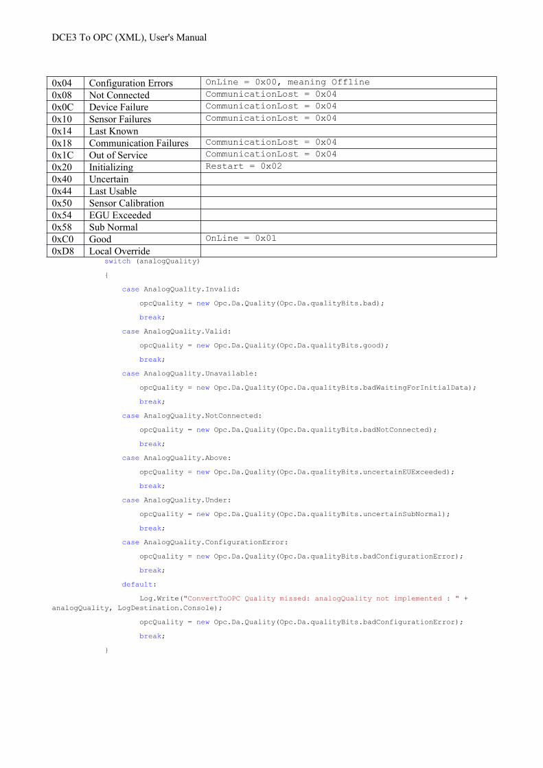
DCE3 Quality value Mappings to OPC Value Description Maps to DCE3 as0x00 Bad OnLine = 0x00, meaning Offline
DCE3 To OPC (XML), User's Manual
0x04 Configuration Errors OnLine = 0x00, meaning Offline
0x08 Not Connected CommunicationLost = 0x04
0x0C Device Failure CommunicationLost = 0x04
0x10 Sensor Failures CommunicationLost = 0x04
0x14 Last Known0x18 Communication Failures CommunicationLost = 0x04
0x1C Out of Service CommunicationLost = 0x04
0x20 Initializing Restart = 0x02
0x40 Uncertain0x44 Last Usable0x50 Sensor Calibration0x54 EGU Exceeded0x58 Sub Normal0xC0 Good OnLine = 0x01
0xD8 Local Override switch (analogQuality)
{
case AnalogQuality.Invalid:
opcQuality = new Opc.Da.Quality(Opc.Da.qualityBits.bad);
break;
case AnalogQuality.Valid:
opcQuality = new Opc.Da.Quality(Opc.Da.qualityBits.good);
break;
case AnalogQuality.Unavailable:
opcQuality = new Opc.Da.Quality(Opc.Da.qualityBits.badWaitingForInitialData);
break;
case AnalogQuality.NotConnected:
opcQuality = new Opc.Da.Quality(Opc.Da.qualityBits.badNotConnected);
break;
case AnalogQuality.Above:
opcQuality = new Opc.Da.Quality(Opc.Da.qualityBits.uncertainEUExceeded);
break;
case AnalogQuality.Under:
opcQuality = new Opc.Da.Quality(Opc.Da.qualityBits.uncertainSubNormal);
break;
case AnalogQuality.ConfigurationError:
opcQuality = new Opc.Da.Quality(Opc.Da.qualityBits.badConfigurationError);
break;
default:
Log.Write("ConvertToOPC Quality missed: analogQuality not implemented : " + analogQuality, LogDestination.Console);
opcQuality = new Opc.Da.Quality(Opc.Da.qualityBits.badConfigurationError);
break;
}
DCE3 To OPC (XML), User's Manual
Timestamps
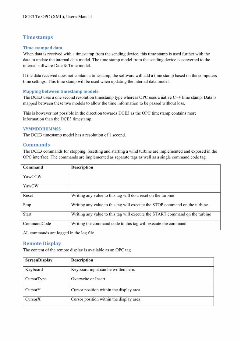
Time stamped dataWhen data is received with a timestamp from the sending device, this time stamp is used further with the data to update the internal data model. The time stamp model from the sending device is converted to the internal software Date & Time model.
If the data received does not contain a timestamp, the software will add a time stamp based on the computers time settings. This time stamp will be used when updating the internal data model.
Mapping between timestamp modelsThe DCE3 uses a one second resolution timestamp type whereas OPC uses a native C++ time stamp. Data is mapped between these two models to allow the time information to be passed without loss.
This is however not possible in the direction towards DCE3 as the OPC timestamp contains more information than the DCE3 timestamp.
YYMMDDHHMMSSThe DCE3 timestamp model has a resolution of 1 second.
CommandsThe DCE3 commands for stopping, resetting and starting a wind turbine are implemented and exposed in theOPC interface. The commands are implemented as separate tags as well as a single command code tag.
Command Description
YawCCW
YawCW
Reset Writing any value to this tag will do a reset on the turbine
Stop Writing any value to this tag will execute the STOP command on the turbine
Start Writing any value to this tag will execute the START command on the turbine
CommandCode Writing the command code to this tag will execute the command
All commands are logged in the log file
Remote DisplayThe content of the remote display is available as an OPC tag.
ScreenDisplay Description
Keyboard Keyboard input can be written here.
CursorType Overwrite or Insert
CursorY Cursor position within the display area
CursorX Cursor position within the display area

DCE3 To OPC (XML), User's Manual
Content The contents of the display area are displayed with 40 characters for each line.Special characters are coded as two byte Unicode chars.
The Remote Panel is also available as a web page implementing the remote panel so that the turbine may be operated remotely.
Communication
Stability of communicationIn a production environment the communication lines are instable. This means that the software was designed to recover from communications failures in both directions. If a TCP connection was dropped from some reason the connecting party will attempt to reconnect.
If the OPC server is disconnected for some reason, the Service will reconnect once it becomes available. Thisalso applies to the startup sequence of the services, thus there are no special requirements for the OPC server to start and be operational before the IEC DCE3 service starts.
Reconnect attemptsWhenever a DCE3 station is disconnected, the service will try to reconnect to the TCP address and port, subsequent reconnect attempts will be paused for 10 seconds.
Idle timeIf no TCP/IP traffic is detected on the connection for the idle time, the connection is shut down.
Prioritized Communication
Data RequestData requests have ordinary priority and are queued. New requests for data telegrams already in the communication queue are discarded.
DisplayWhenever a Remote display request is received by the OPC data gateway, this has a higher priority in the internal data request queue I order to have a quick response when operating the remote panel. This higher priority is maintained as long as there is user activity on the Remote panel.
Key strokesKeystrokes from the remote pane have high priority.
CommandsTurbine commands have highest priority and are executed before all data requests and Panel communication.
Polling StrategiesIn a single park with one TCP connection, each turbine is identified by it s node number in the DCE3 telegram, due to limitations in the packet switch function in the TAC controller serving as a Router in the park, communication must be done as a Round Robin polling scheme.
DCE3 To OPC (XML), User's Manual
Requesting wind speed data from all controllers will thus have to be done sequentially and it may take 10 seconds to request data from 20 turbines.
OPC SubscriptionsOPC groups should be created for data that is needed at a regular basis; the refresh rate of the group is used as a guideline for the internal data refresh polling cycle.
The OPC group created by the client should contain data from a single turbine.
The refresh rate of the group should match the expected refresh rate of the data, thus having a 1 Hz ( 1000 ms) refresh rate for calculated 10 minute average data on the turbine does not make sense as these data do not update quicker that every 10*60*1000 milliseconds.
Historical dataWhen acquiring historical data, for instance 10 minute logs, a subscription should be maintained for the first row of data (the latest 10 minute data available).
Whenever data is missing in the OPC Client’s 10 minute data model, data can be read from the server, this may result in two different cases, either the data is there and this returned to the OPC client which in turn may complete it own data model, or the data is not there and OPC Quality will inform about the missing data. The Server will then try to request the data from the DCE3 device and complete the internal data cache in the DCE3 server this may take some seconds to minutes depending on the data traffic on the server. After the data is received it will be available for read.
Data integrity during a systems (re) startWhen the Computer or OS is restarted or a windows service fails, the Service will be started by the system. This may lead to discrepancies in the data model internally in the software compared with the communicating devices in the first few seconds or milliseconds of operation.
The internal name-space is built as the first step and all data items will have a timestamp set to 0 meaning thefirst possible data in the date time model. The quality will be set at invalid. The software will not by itself send any data to clients.
Once the DCE3 master connects (or reconnects) to the software it may read the data from the internal data model. The data here may be invalid and the quality information and time stamps will inform about this.
Set-point’sThe most critical data during a start or restart are set-point values. These data are not written to the OPC server during restart thus is s ONLY when the DCE3 Master decides to write a set-point to the Service that this data is written to the OPC server.
Quite often a write back item is created; this means that for every IEC DCE3 Set-point value there is a corresponding value that will be updated in the opposite direction. This will only be updated by the OPC server when the OPC server has accepted the value. The DCE3 Master must monitor these two value pairs. The time delay in updating the OPC server should be in the 100 millisecond range but may differ based on the reporting interval on the data subscriptions.
There are only a few tags that may be written to the turbine, most are only available for read.

DCE3 To OPC (XML), User's Manual
The most common are the set-points for active and reactive power and the date time tag
SecuritySecurity is a major concern in the design of power systems, as there is no “built in” security mechanism in the IEC DCE3 standard, special care must be taken in the design of the network to ensure network security on the link layer.
The DCE3 link layer implementation logs all connect requests.
Non DCE3 traffic on the socket connection is logged.
Commands are always logged.
ConformanceTo the best of our knowledge the solution conforms to both the IEC DCE3 Standard and the IEC OPC (XML) standard, both are evolving continuously. We follow the ongoing work on these standards as well as the outcome of interoperability tests. Special focus is on the security aspects of both standards.
InteroperabilityThe solution has been extensively tested with a range of OPC client software packages.
A range of DCE3 turbine controllers have been used to verify the DCE3 interface.
Configuring SCADA packages
NamesThe names in the OPC server are the names configured in the XML configuration file for the commands.
The names are by default the names used by the DCE3 protocol, but may be changed for e.x. IEC 61400-25 compatible names.
It is no small task to understand what data is associated with the command elements and their names.
SubscriptionsData that needs a regular update should be configured with a subscription group on the OPC XML server. When the data is not required by the SCADA client the subscription should be cancelled to avoid polling the DCE3 device for data that are not needed.
ReadData that are only requested from time to time should be read from the OPC server with a Read, this will generate one or more read operations to the DCE3 device depending on the command elements containing the data.
Once the data has been retrieved it will be available in the server with quality and timestamp.
Both Read & Subscriptions will read the dataset’s needed to get the data requested, thus there will be more data available in the server than was originally requested by the OPC client.

DCE3 To OPC (XML), User's Manual
SI unitsThe engineering units of a DCE3 name may be configured in the xml configuration file, OPC XML unfortunately does not handle SI units particularly well, and thus it is up to the SCADA package and configuration to handle the units like Watt, Kilo Watt etc correct.
There may be a difference in the SI units used in different controllers, TACI or TACII, and software versionsused on the controller.
PerformanceThere are several issues that may impact performance, the software here is an invisible middle-ware that has no user interface so it may be difficult the see what influences performance.
Performance is best understood as the ability to expose data on the OPC side and to keep it updated. The quality of the underlying network that transports the physical packages may seriously decrease the update speed.
The OPC server will for instance not report values back when an object is written as this would conflict with the group update frequency policy or “dead band” analysis.
The protocol is an request response type of protocol, so date has to be polled for each update. The distance between the server and the turbine as well as the speed of the network in between impacts the number of datapoints that can be updated in a 10 second cycle. A typical response time when communicating with the turbine in the park is in the 25-50 millisecond range, in a 4G network, this may increase to 2,5 second for a request response. So placing the software and OPC server in the park will enable 100 time the updat erate of tags compared to the remote 4G based monitoring case.
How to measureUse an automated test script in the OPC server to update data at a predefined rate and verify the data integrity on the DCE3 Master side.
Prioritized commandsAll turbine commands and Remote display requests are handled internally as higher priority requests than ordinary data requests.
Do not subscribe on 10 minute data series with a 3 second refresh rate
DCE3 protocol MultiplexingDCE3 for the TAC I & TAC II controller is a request response protocol based on serial communications where the controller is connected thru a RS232 or 485 cable to the controlling station. A Modem may be used to establish a dialup connection to the controller. This setup would effectively limit the number of communicating DCE3 masters to one at the time.
In a setup with a TCP/IP communications between a TAC II and controlling station or SCADA, it would be possible to have multiple clients’ request data from the controller; however the DCE3 protocol was not built for this purpose.
DCE3 To OPC (XML), User's Manual
Throttle data requests when a RemotePanel is in sessionWhen a user is working with the RemotePanel it is vital for the performance, that other communication requesting online data is limited so that keystrokes and the panel response are seen within second(s).
It is important to throttle the Multiplexing clients DCE3 communication during a RemotePanel session as theother clients does not know of the current RemotePanel session.
StarvationA priority queue is used to hold messages from all communicating clients so that no single client can monopolize the communication.
Reuse of data DCE3 response messagesData requested by the Multiplexing client’s will be consumed by the multiplexer to keep its own OPC server updated with data thus effectively limiting the need for own data requests.
ConfigurationEach multiplexing channel is a pair of a local address & port with a remote address & port.
The multiplexer will open each local port and listen for an incoming connection.
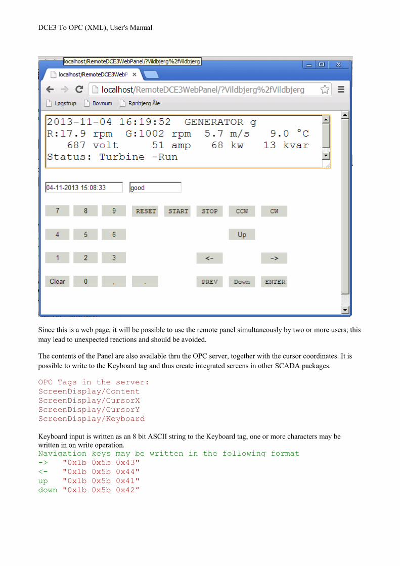
WEB Remote DisplayA HTML version of the navigation display on the turbine has been implemented so that the display may be used from any web client including a Smartphone.
The ASP page communicates with the OPC service to request data from the device and send keyboard input.
Please note that there are severe security issues when using the Remote Display as the Remote Display bypasses normal security procedures on the turbine. This may lead to a situation where a service person in the turbine may be put in risk by a person that remotely starts the turbine.
DCE3 To OPC (XML), User's Manual
Since this is a web page, it will be possible to use the remote panel simultaneously by two or more users; thismay lead to unexpected reactions and should be avoided.
The contents of the Panel are also available thru the OPC server, together with the cursor coordinates. It is possible to write to the Keyboard tag and thus create integrated screens in other SCADA packages.
OPC Tags in the server:ScreenDisplay/ContentScreenDisplay/CursorXScreenDisplay/CursorYScreenDisplay/Keyboard
Keyboard input is written as an 8 bit ASCII string to the Keyboard tag, one or more characters may be written in on write operation.Navigation keys may be written in the following format-> "0x1b 0x5b 0x43"<- "0x1b 0x5b 0x44"up "0x1b 0x5b 0x41"down "0x1b 0x5b 0x42”
DCE3 To OPC (XML), User's Manual
Subscriptions on the contents and coordinates should ONLY be maintained by the OPC client when there is aregular interaction with the turbine by the User. The use of the panel or a subscription on the contents will limit the flow of other data packages from the turbine and thus have a negative impact on the number of the data tags that may be updated.
The communication with the Panel is prioritized and is executed by the server before queued data requests.
Installation
Application poolThe web page should have its own Application pool in order to co-exist with other web applications using different versions of .Net
The actual configuration of the application pool depends on the version of IIS installed.
Diagnostics
Suggested test setup for software verificationAny OPC UA Client can be used for writing values to i.e. set-points.
If an automated write sequence is used in the OPC server, and a subscription has been made in the OPC client configuration of the Service, then the values are seen in the DCE3 Master in regular intervals.
DCE3OPCServer diagnosticsThere are two main sources of information regarding the operational status of the Service; the Windows system log and the log files found in the application path.
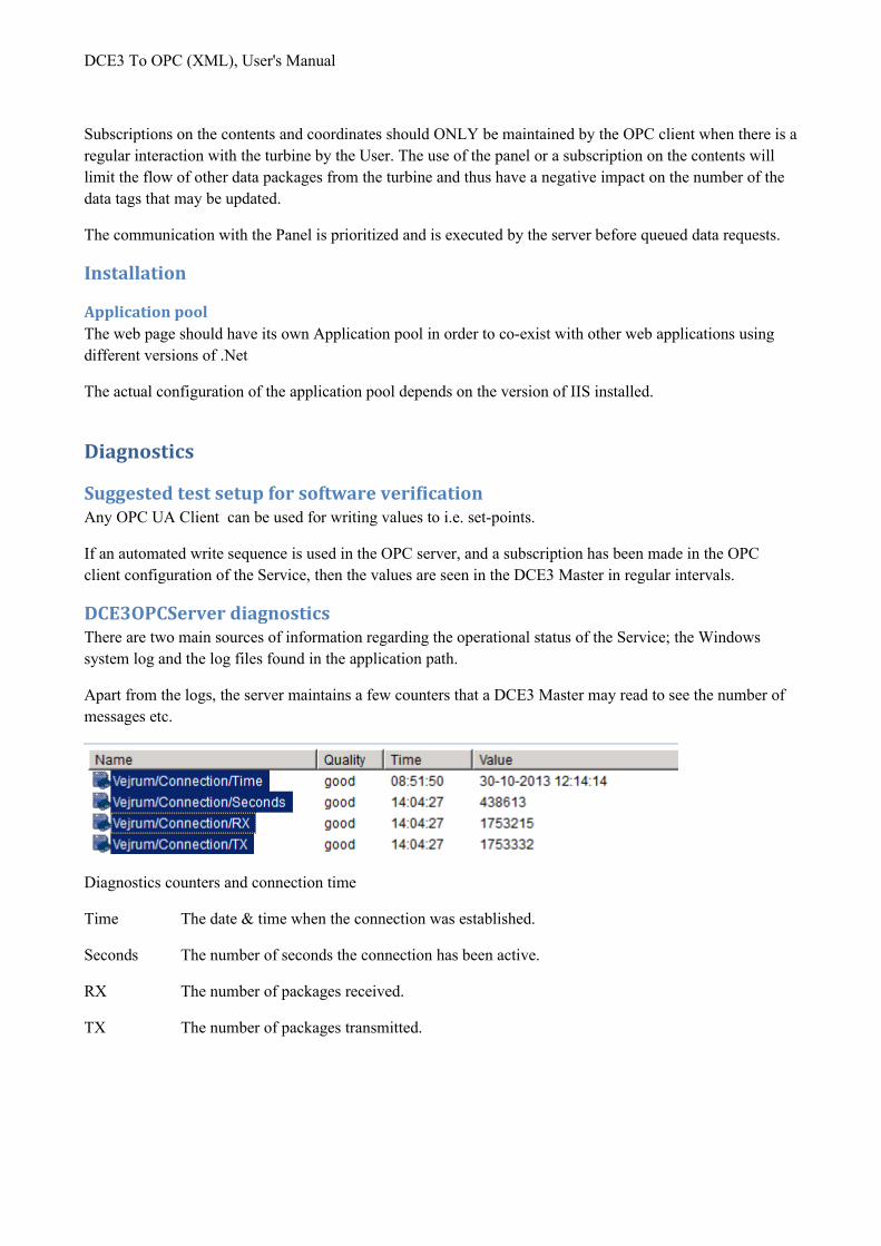
Apart from the logs, the server maintains a few counters that a DCE3 Master may read to see the number of messages etc.
Diagnostics counters and connection time
Time The date & time when the connection was established.
Seconds The number of seconds the connection has been active.
RX The number of packages received.
TX The number of packages transmitted.
DCE3 To OPC (XML), User's Manual
Console modeA second option is to run the service exe with the –console option and thus starting it in console mode. This will give you a view of the processed telegrams. The –console option is not to be used for production mode or performance analysis.
The console must be running with administrator rights,
The service must be stopped prior to running as console,
logging may be set to 31 decimal
use the following command DCE3ToOPCUA.exe -console
LoggingTo change logging frequency You need to open bin/DCE3ToOPCXMLService.exe.config , find record:
<add key="LogEvents" value="31" />
and change value according to this:
<!--
Exception = 0x0001,
Error = 0x0002,
Warning = 0x0004,
Info = 0x0008,
Diagnostics = 0x0010,
-->
where Exception is the least amount of logs and Diagnostics is the most.
Warning, Info and Diagnostics should not be used for production as this will eventually fill the disk with log information.
<add key="LogFile" value="C:\inetpub\wwwroot\DCE3ToOPCXML\Log\Log.txt"/>
is used to control where the log file is located and what its name should be.
Contact usWindows Sp z o. o.
www.ess.pl

DCE3 To OPC (XML), User's Manual
Appendix. Namespace