Embed Size (px)
Citation preview

DC3E Non-Regenerative DC DriveUser Guide1/4 to 2 HP, 115/230 VAC
Instruction Manual D2-3452-1
M/N DC3N-12D-00-010-AIM/N DC3N-12D-4X-010-AI
250-0287-rev2.qxd 3/12/01 10:27 AM Page a
Trademarks not belonging to Rockwell Automation are property of their respective companies. ©2001 Rockwell International Corporation All rights reserved
The information in this manual is subject to change withoutnotice.
Throughout this manual, the following notes are used to alertyou to safety considerations:
ATTENTION: Identifies information about practices orcircumstances that can lead to personal injury or death,property damage, or economic loss.
mIMPORTANT: Identifies information that is critical for successfulapplication and understanding of the product.
250-0287-rev2.qxd 3/12/01 10:27 AM Page b
i
ATTENTION: Only qualified personnel familiar with theconstruction and operation of this equipment and thehazards involved should install, adjust, operate, and/orservice this equipment. Read and understand thisinstruction manual in its entirety before proceeding.Failure to observe this precaution could result in severebodily injury or loss of life.
ATTENTION: The user is responsible for conformingwith all applicable local and national codes. Failure toobserve this precaution could result in severe bodilyinjury or loss of life.
ATTENTION: The control circuit is at line potentialwhen the drive is energized. Use a non-metallicscrewdriver when making adjustments to the circuitboard potentiometers. Exercise extreme caution ashazardous voltage exists. Failure to observe theseprecautions could result in severe bodily injury or loss oflife.
ATTENTION: It is possible for a drive to run at fullspeed as a result of a component failure. Pleaseensure that a master switch has been placed in the ACline to stop the drive in an emergency.
ATTENTION: Reduce the chance of an electrical fire,shock, or explosion by proper grounding, over-currentprotection, thermal protection and enclosure. Followsound maintenance procedures.
m
250-0287-rev2.qxd 3/12/01 10:27 AM Page i
ii Safety Warnings
ATTENTION: Starting and stopping with the start/stopterminals does not disconnect AC power in the stopposition. A hardwired AC power disconnection switchmust be mounted between the AC source and terminalsL I and L2. This is required, as the DC drive does nothave an armature loop contactor. A single fault like apower device short may cause motor rotation when inthe stop mode. The user is responsible for assuring safeconditions for operating personnel by providing suitableguards, audio or visual alarms, or other devices. Failureto observe these precautions could result in bodily injury.
ATTENTION: This Drive contains ESD (Electric StaticDischarge) sensitive parts and assemblies, Static controlprecautions are required when installing, testing,servicing, or repairing this assembly. Failure to observethese precautions could result in damage to, ordestruction of, the equipment.
m
250-0287-rev2.qxd 3/12/01 10:27 AM Page ii
Specifications 1
Dimensions and Layout 4
Installation 7Wiring . . . . . . . . . . . . . . . . . . . . . . . . . . . . . . . . . . . . . . . . . . . . . . .8
Shielding guidelines . . . . . . . . . . . . . . . . . . . . . . . . . . . . . . . . . .8Chassis drive . . . . . . . . . . . . . . . . . . . . . . . . . . . . . . . . . . . . . . . .10
Mounting . . . . . . . . . . . . . . . . . . . . . . . . . . . . . . . . . . . . . . . . . .10Isolation transformer . . . . . . . . . . . . . . . . . . . . . . . . . . . . . . . . . .11Heat sinking . . . . . . . . . . . . . . . . . . . . . . . . . . . . . . . . . . . . . . .12Fusing . . . . . . . . . . . . . . . . . . . . . . . . . . . . . . . . . . . . . . . . . . . .12
Line fusing . . . . . . . . . . . . . . . . . . . . . . . . . . . . . . . . . . . . . .13Speed adjust potentiometer . . . . . . . . . . . . . . . . . . . . . . . . . . . .14
Alternate speed adjust potentiometer connections . . . . . . . . .15Cage-clamp terminals . . . . . . . . . . . . . . . . . . . . . . . . . . . . . . .16Connections . . . . . . . . . . . . . . . . . . . . . . . . . . . . . . . . . . . . . . . .17
Motor . . . . . . . . . . . . . . . . . . . . . . . . . . . . . . . . . . . . . . . . . . .18Power input . . . . . . . . . . . . . . . . . . . . . . . . . . . . . . . . . . . . . .19Field output . . . . . . . . . . . . . . . . . . . . . . . . . . . . . . . . . . . . . .20START/STOP pushbuttons . . . . . . . . . . . . . . . . . . . . . . . . . . .21Tachometer feedback . . . . . . . . . . . . . . . . . . . . . . . . . . . . . . .22Voltage or current follower . . . . . . . . . . . . . . . . . . . . . . . . . . .24
Enclosed drive . . . . . . . . . . . . . . . . . . . . . . . . . . . . . . . . . . . . . . .25Mounting . . . . . . . . . . . . . . . . . . . . . . . . . . . . . . . . . . . . . . . . . .25Heat sinking . . . . . . . . . . . . . . . . . . . . . . . . . . . . . . . . . . . . . . .26Line fusing . . . . . . . . . . . . . . . . . . . . . . . . . . . . . . . . . . . . . . . . .26Connections . . . . . . . . . . . . . . . . . . . . . . . . . . . . . . . . . . . . . . . .27
Motor . . . . . . . . . . . . . . . . . . . . . . . . . . . . . . . . . . . . . . . . . . .28Power input . . . . . . . . . . . . . . . . . . . . . . . . . . . . . . . . . . . . . .29
Contents
iii
250-0287-rev2.qxd 3/12/01 10:27 AM Page iii
Field output . . . . . . . . . . . . . . . . . . . . . . . . . . . . . . . . . . . . . .29Tachometer feedback . . . . . . . . . . . . . . . . . . . . . . . . . . . . . . .30Voltage or current follower . . . . . . . . . . . . . . . . . . . . . . . . . . .32
Slide switches . . . . . . . . . . . . . . . . . . . . . . . . . . . . . . . . . . . . . . . .33LINE VOLTAGE (SW501 and SW502) . . . . . . . . . . . . . . . . . . . .33MOTOR (SW503) . . . . . . . . . . . . . . . . . . . . . . . . . . . . . . . . . . .33SIGNAL (SW504) . . . . . . . . . . . . . . . . . . . . . . . . . . . . . . . . . . .34FEEDBACK (SW505) . . . . . . . . . . . . . . . . . . . . . . . . . . . . . . . . .34
Operation 36Before applying power (all models) . . . . . . . . . . . . . . . . . . . . . . . . .37Drive operation . . . . . . . . . . . . . . . . . . . . . . . . . . . . . . . . . . . . . . .38
Chassis drive operation . . . . . . . . . . . . . . . . . . . . . . . . . . . . . . .38POWER ON start . . . . . . . . . . . . . . . . . . . . . . . . . . . . . . . . .38Pushbutton start/stop . . . . . . . . . . . . . . . . . . . . . . . . . . . . . . .39
Alternate Starting and Stopping Methods . . . . . . . . . . . . . . . . . .41Minimum speed . . . . . . . . . . . . . . . . . . . . . . . . . . . . . . . . . . .42Dynamic braking . . . . . . . . . . . . . . . . . . . . . . . . . . . . . . . . . .43Dynamic brake resistor value . . . . . . . . . . . . . . . . . . . . . . . .43
Enclosed drive operating modes . . . . . . . . . . . . . . . . . . . . . . . . .45Manual mode . . . . . . . . . . . . . . . . . . . . . . . . . . . . . . . . . . . .45Auto mode . . . . . . . . . . . . . . . . . . . . . . . . . . . . . . . . . . . . . .46
Enclosed drive operation . . . . . . . . . . . . . . . . . . . . . . . . . . . . . .46To run the motor . . . . . . . . . . . . . . . . . . . . . . . . . . . . . . . . . . .47To stop the motor . . . . . . . . . . . . . . . . . . . . . . . . . . . . . . . . .47
Calibration 48Drive Calibration Procedure . . . . . . . . . . . . . . . . . . . . . . . . . . . . .50
MIN SPD . . . . . . . . . . . . . . . . . . . . . . . . . . . . . . . . . . . . . . . . . .51MAX SPD . . . . . . . . . . . . . . . . . . . . . . . . . . . . . . . . . . . . . . . . .52CURRENT LIMIT . . . . . . . . . . . . . . . . . . . . . . . . . . . . . . . . . . . .53IR COMP . . . . . . . . . . . . . . . . . . . . . . . . . . . . . . . . . . . . . . . . .54
Approximate IR COMP calibration: . . . . . . . . . . . . . . . . . . . .55ACCEL . . . . . . . . . . . . . . . . . . . . . . . . . . . . . . . . . . . . . . . . . . .55
iv Table of Contents
250-0287-rev2.qxd 3/12/01 10:27 AM Page iv
DECEL . . . . . . . . . . . . . . . . . . . . . . . . . . . . . . . . . . . . . . . . . . .56TACH VOLTS . . . . . . . . . . . . . . . . . . . . . . . . . . . . . . . . . . . . . . .57
Application Notes 60Multiple fixed speeds . . . . . . . . . . . . . . . . . . . . . . . . . . . . . . . . . . .60Adjustable speeds using potentiometers in series . . . . . . . . . . . . .61Independent adjustable speeds . . . . . . . . . . . . . . . . . . . . . . . . . . .62Reversing . . . . . . . . . . . . . . . . . . . . . . . . . . . . . . . . . . . . . . . . . . .63RUN/JOG switch . . . . . . . . . . . . . . . . . . . . . . . . . . . . . . . . . . . . . .65Before troubleshooting . . . . . . . . . . . . . . . . . . . . . . . . . . . . . . . . .67
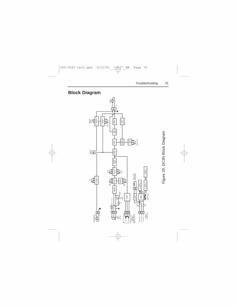
Troubleshooting 67Diagnostic LEDs . . . . . . . . . . . . . . . . . . . . . . . . . . . . . . . . . . . . . .68Block Diagram . . . . . . . . . . . . . . . . . . . . . . . . . . . . . . . . . . . . . . . .75Terminal descriptions . . . . . . . . . . . . . . . . . . . . . . . . . . . . . . . . . .76
Chassis drive terminals . . . . . . . . . . . . . . . . . . . . . . . . . . . . . . .76Enclosed drive terminals . . . . . . . . . . . . . . . . . . . . . . . . . . . . . .77
CE Compliance 78Exhibit “A” . . . . . . . . . . . . . . . . . . . . . . . . . . . . . . . . . . . . . . . . . . .79Armature Filters . . . . . . . . . . . . . . . . . . . . . . . . . . . . . . . . . . . . . .80
Notes 82
vTable of Contents
250-0287-rev2.qxd 3/12/01 10:27 AM Page v
Figure 1. DC3N-12D-00-010-AI Dimensions . . . . . . . . . . . . . . . . . .4Figure 2. DC3N-12D-4X-010-AI Dimensions . . . . . . . . . . . . . . . . . .5Figure 3. PC Board Layout . . . . . . . . . . . . . . . . . . . . . . . . . . . . . . .6Figure 4. Speed Adjust Potentiometer . . . . . . . . . . . . . . . . . . . . . .14Figure 5. Cage-Clamp Terminal . . . . . . . . . . . . . . . . . . . . . . . . . . .16Figure 6. Chassis Drive Connections . . . . . . . . . . . . . . . . . . . . . . .23Figure 7. Chassis Drive Signal Follower Connection . . . . . . . . . . .24Figure 8. Enclosed Drive Connections . . . . . . . . . . . . . . . . . . . . . .31Figure 9. Slide Switches . . . . . . . . . . . . . . . . . . . . . . . . . . . . . . . .35Figure 10. Run/Decelerate to Minimum Speed Switch . . . . . . . . . . .42Figure 11. Dynamic Brake Connection . . . . . . . . . . . . . . . . . . . . . . .44Figure 12. Calibration Trimpot Layout . . . . . . . . . . . . . . . . . . . . . . .49Figure 13. Typical CURRENT LIMIT and IR COMP Settings . . . . . .59Figure 14. Multiple Fixed Speeds . . . . . . . . . . . . . . . . . . . . . . . . . .60Figure 15. Adjustable Fixed Speeds Using Potentiometers in Series 61Figure 16. Independent Adjustable Speeds . . . . . . . . . . . . . . . . . . .62Figure 17. Reversing Circuit Connection . . . . . . . . . . . . . . . . . . . . .64Figure 18. RUN/JOG Switch Connection to Speed Adjust
Potentiometer . . . . . . . . . . . . . . . . . . . . . . . . . . . . . . .66Figure 19. Diagnostic LED Locations . . . . . . . . . . . . . . . . . . . . . . . .68Figure 20. DC3N Block Diagram . . . . . . . . . . . . . . . . . . . . . . . . . . .75
vi
Illustrations
250-0287-rev2.qxd 3/12/01 10:27 AM Page vi
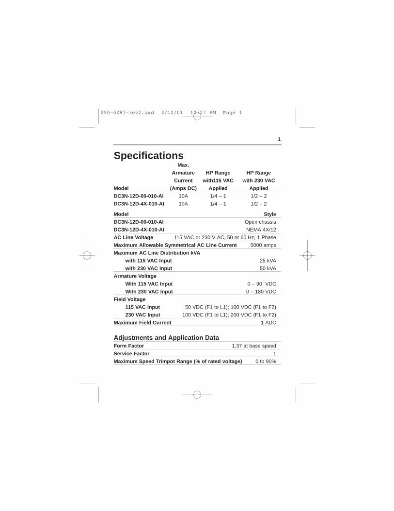
SpecificationsMax.
Armature HP Range HP Range
Current with115 VAC with 230 VAC
Model (Amps DC) Applied Applied
DC3N-12D-00-010-AI 10A 1/4 – 1 1/2 – 2
DC3N-12D-4X-010-AI 10A 1/4 – 1 1/2 – 2
Model Style
DC3N-12D-00-010-AI Open chassis
DC3N-12D-4X-010-AI NEMA 4X/12
AC Line Voltage 115 VAC or 230 V AC, 50 or 60 Hz, 1 Phase
Maximum Allowable Symmetrical AC Line Current 5000 amps
Maximum AC Line Distribution kVA
with 115 VAC Input 25 kVA
with 230 VAC Input 50 kVA
Armature Voltage
With 115 VAC Input 0 – 90 VDC
With 230 VAC Input 0 – 180 VDC
Field Voltage
115 VAC Input 50 VDC (F1 to L1); 100 VDC (F1 to F2)
230 VAC Input 100 VDC (F1 to L1); 200 VDC (F1 to F2)
Maximum Field Current 1 ADC
Adjustments and Application DataForm Factor 1.37 at base speed
Service Factor 1
Maximum Speed Trimpot Range (% of rated voltage) 0 to 90%
1
250-0287-rev2.qxd 3/12/01 10:27 AM Page 1
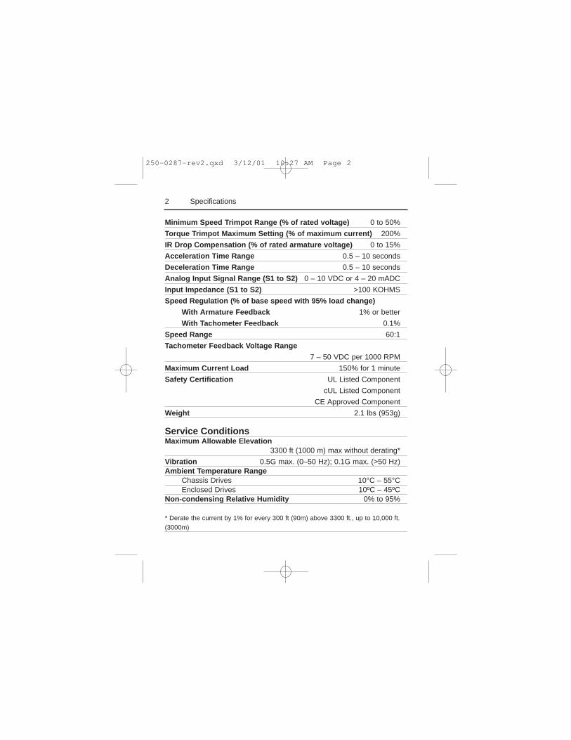
Minimum Speed Trimpot Range (% of rated voltage) 0 to 50%
Torque Trimpot Maximum Setting (% of maximum current) 200%
IR Drop Compensation (% of rated armature voltage) 0 to 15%
Acceleration Time Range 0.5 – 10 seconds
Deceleration Time Range 0.5 – 10 seconds
Analog Input Signal Range (S1 to S2) 0 – 10 VDC or 4 – 20 mADC
Input Impedance (S1 to S2) >100 KOHMS
Speed Regulation (% of base speed with 95% load change)
With Armature Feedback 1% or better
With Tachometer Feedback 0.1%
Speed Range 60:1
Tachometer Feedback Voltage Range
7 – 50 VDC per 1000 RPM
Maximum Current Load 150% for 1 minute
Safety Certification UL Listed Component
cUL Listed Component
CE Approved Component
Weight 2.1 lbs (953g)
Service ConditionsMaximum Allowable Elevation
3300 ft (1000 m) max without derating*
Vibration 0.5G max. (0–50 Hz); 0.1G max. (>50 Hz)Ambient Temperature Range
Chassis Drives 10°C – 55°CEnclosed Drives 10ºC – 45ºC
Non-condensing Relative Humidity 0% to 95%
* Derate the current by 1% for every 300 ft (90m) above 3300 ft., up to 10,000 ft.(3000m)
2 Specifications
250-0287-rev2.qxd 3/12/01 10:27 AM Page 2
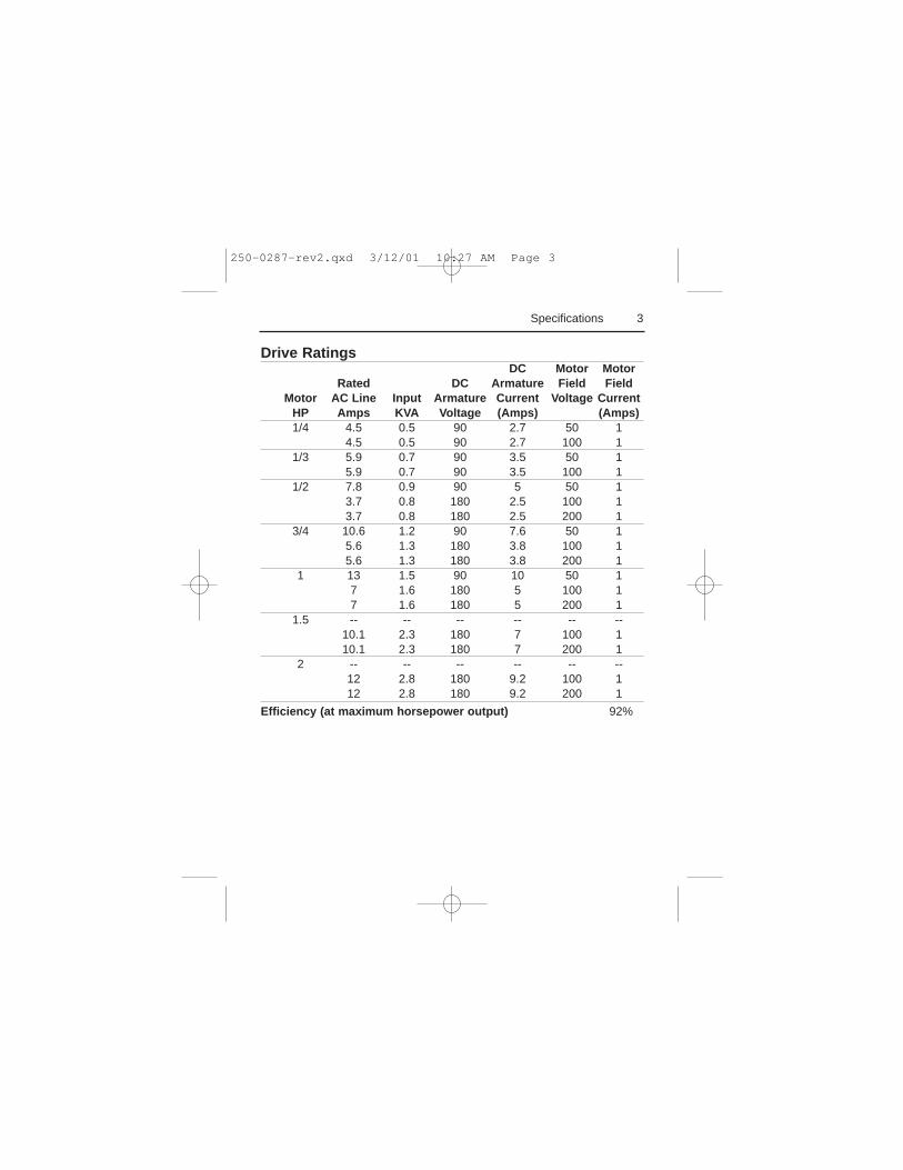
Drive RatingsDC Motor Motor
Rated DC Armature Field FieldMotor AC Line Input Armature Current Voltage Current
HP Amps KVA Voltage (Amps) (Amps)1/4 4.5 0.5 90 2.7 50 1
4.5 0.5 90 2.7 100 11/3 5.9 0.7 90 3.5 50 1
5.9 0.7 90 3.5 100 11/2 7.8 0.9 90 5 50 1
3.7 0.8 180 2.5 100 13.7 0.8 180 2.5 200 1
3/4 10.6 1.2 90 7.6 50 15.6 1.3 180 3.8 100 15.6 1.3 180 3.8 200 1
1 13 1.5 90 10 50 17 1.6 180 5 100 17 1.6 180 5 200 1
1.5 -- -- -- -- -- --10.1 2.3 180 7 100 110.1 2.3 180 7 200 1
2 -- -- -- -- -- --12 2.8 180 9.2 100 112 2.8 180 9.2 200 1
Efficiency (at maximum horsepower output) 92%
3Specifications
250-0287-rev2.qxd 3/12/01 10:27 AM Page 3
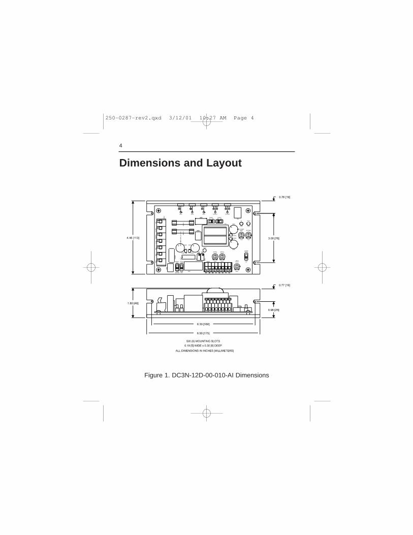
4
Dimensions and Layout
Figure 1. DC3N-12D-00-010-AI Dimensions
250-0287-rev2.qxd 3/12/01 10:27 AM Page 4
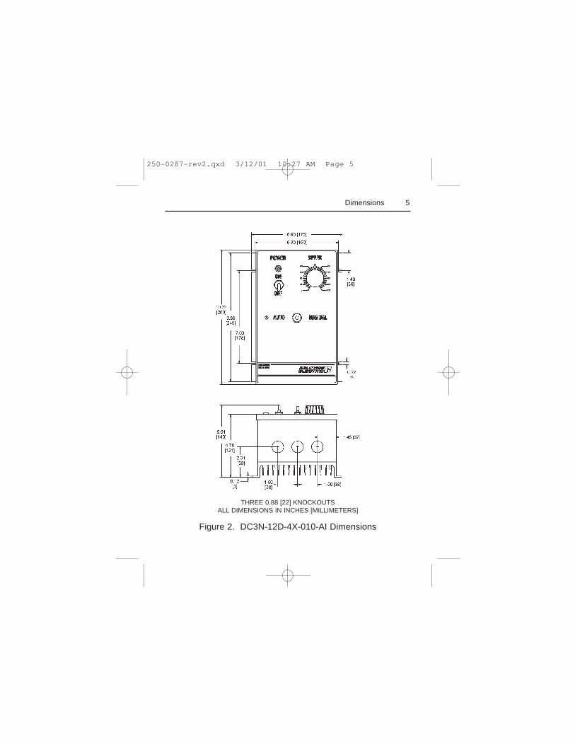
5Dimensions
THREE 0.88 [22] KNOCKOUTSALL DIMENSIONS IN INCHES [MILLIMETERS]
Figure 2. DC3N-12D-4X-010-AI Dimensions
250-0287-rev2.qxd 3/12/01 10:27 AM Page 5
6 Dimensions and Layout
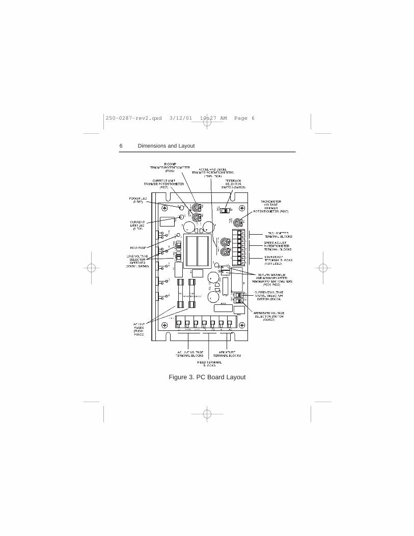
Figure 3. PC Board Layout
250-0287-rev2.qxd 3/12/01 10:27 AM Page 6
7
Installation
ATTENTION: Only qualified technical personnel,familiar with the construction and operation of thisequipment and the hazards involved, should install,adjust, operate and/or service this equipment. Read andunderstand this instruction manual in its entirety beforeproceeding. Failure to observe this precaution couldresult in severe bodily injury or loss of life.
ATTENTION: This equipment is at line voltage whenAC power is connected. Disconnect and lockout allungrounded conductors of the AC power line beforeworking on the unit. Failure to observe this precautioncould result in severe bodily injury or loss of life.
ATTENTION: The user is responsible for conformingwith all applicable local and national codes. Failure toobserve this precaution could result in severe bodilyinjury or loss of life.
m
250-0287-rev2.qxd 3/12/01 10:27 AM Page 7
Wiring
8 Installation
ATTENTION: Circuit potentials are at 115 or 230VAC above ground. To prevent the risk of injury orfatality, avoid direct contact with the printed circuitboard or with circuit elements. Use a non-metallicscrewdriver for the calibration trimpots.
ATTENTION: Do not disconnect any of the motorleads from the drive unless power is removed or thedrive is disabled. Opening any one motor lead maydestroy the drive.
m
Use 18-24 AWG wire for speed adjust potentiometerwiring. Use 14–16 AWG wire for AC line (L1, L2) andmotor (A1 and A2) wiring.
Shielding guidelines
ATTENTION: If it is not practical to shield powerconductors, Reliance Electric recommends shielding alllogic-level leads. If shielding logic leads is notpractical, use twisted-pair control wiring to minimizeinduced electrical noise.
m
250-0287-rev2.qxd 3/12/01 10:27 AM Page 8
9Installation
*Reliance Electric considers this an unfavorable condition and does not
recommend bundling power and logic leads for any length.
ATTENTION: Under no circumstances should powerand logic leads be bundled together. Induced voltagecan cause unpredictable behavior any electronic device,including motor controls.
m
As a general rule, Reliance Electric recommends shieldingof all conductors if:
1) wire lengths exceed 4 inches and power and logic leadsmust be bundled together*; or2) radiated and/or conducted noise must be minimized dueto concerns about immunity or general compliance (CE,FCC, etc.)
It may be necessary to earth ground the shielded cable. Ifnoise is produced by devices other than the drive, groundthe shield at the drive end. If noise is generated by adevice on the drive, ground the shield at the end away fromthe drive. Do not ground both ends of the shield.
If the device continues to pick up noise after grounding theshield, it may be necessary to add AC line filtering devices,or to mount the drive in a less noisy environment.
250-0287-rev2.qxd 3/12/01 10:27 AM Page 9
10 Installation
Mounting
Protect the drive from dirt, moisture, and accidentalcontact. Provide sufficient room for access to the terminalblock and calibration trimpots.
Mount the drive away from other heat sources. Operate thedrive within the specified ambient operating temperaturerange.
Prevent loose connections by avoiding excessive vibrationof the drive.
Mount the drive with its board in either a horizontal orvertical plane. Four 0.19 inch (5 mm) wide slots in thechassis accept #8 pan head screws.
ATTENTION: This drive contains ESD (Electric StaticDischarge) sensitive parts and assemblies. Static controlprecautions are required when installing, testing,servicing, or repairing this assembly. Failure to observethese precautions could result in damage to, ordestruction of, the equipment.
m
Chassis drive
250-0287-rev2.qxd 3/12/01 10:27 AM Page 10
The chassis units do not have to be earth grounded. If youchoose to ground the chassis, use a star washer beneath thehead of at least one of the mounting screws to penetrate theanodized chassis surface and to reach bare metal.
Isolation transformer
11Installation
ATTENTION: Distribution system capacity above themaximum recommended system KVA requires the useof an isolation transformer, a line reactor, or othermeans of adding similar impedance to the drive powerinput. Failure to observe these precautions could resultin damage to, or destruction of, the equipment
m
Input isolation transformers might be needed to helpeliminate the following:
· Damaging line voltage transients from reaching thedrive.
· Line noise from the drive back to the incoming powersource.
· Damaging currents that could develop if a point insidethe drive becomes grounded.
250-0287-rev2.qxd 3/12/01 10:27 AM Page 11
12 Installation
ATTENTION: Most code requires that upstreambranch protection be provided to protect input powerwiring. Failure to observe this precaution could result insevere bodily injury or loss of life.
m
Observe the following guidelines when installing anisolation transformer:
· A power disconnecting device must be installed betweenthe power line and primary of the transformer.
· If the power disconnecting device is a circuit breaker, thecircuit breaker trip rating must be coordinated with thein-rush current (10-12 times full load current) of thetransformer.
Heat sinking
This DC3 drive model contains sufficient heat sinking inits original configuration. No additional heat sinking isnecessary when installed in accordance with the guidelinesspecified in this instruction manual. The chassis plate actsas the thermal heatsink.
Fusing
Install the required, user-supplied branch circuit protectionfuses according to the applicable local, national, andinternational codes (e.g., NEC/CEQ).
250-0287-rev2.qxd 3/12/01 10:27 AM Page 12
13Installation
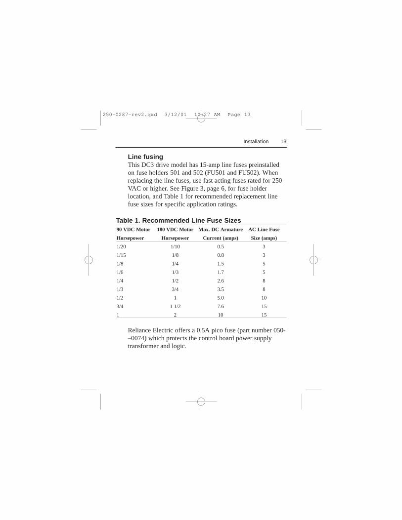
Line fusingThis DC3 drive model has 15-amp line fuses preinstalledon fuse holders 501 and 502 (FU501 and FU502). Whenreplacing the line fuses, use fast acting fuses rated for 250VAC or higher. See Figure 3, page 6, for fuse holderlocation, and Table 1 for recommended replacement linefuse sizes for specific application ratings.
Table 1. Recommended Line Fuse Sizes90 VDC Motor 180 VDC Motor Max. DC Armature AC Line Fuse
Horsepower Horsepower Current (amps) Size (amps)
1/20 1/10 0.5 3
1/15 1/8 0.8 3
1/8 1/4 1.5 5
1/6 1/3 1.7 5
1/4 1/2 2.6 8
1/3 3/4 3.5 8
1/2 1 5.0 10
3/4 1 1/2 7.6 15
1 2 10 15
Reliance Electric offers a 0.5A pico fuse (part number 050-–0074) which protects the control board power supplytransformer and logic.
250-0287-rev2.qxd 3/12/01 10:27 AM Page 13
14
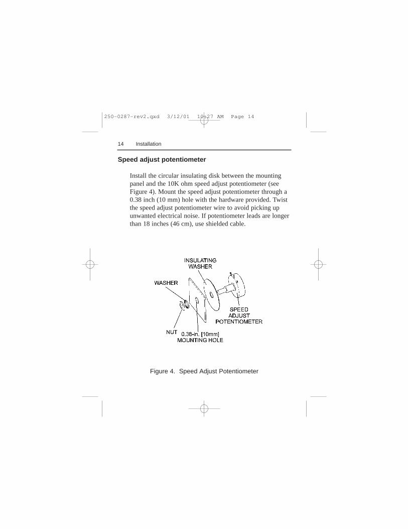
Figure 4. Speed Adjust Potentiometer
Installation
Speed adjust potentiometer
Install the circular insulating disk between the mountingpanel and the 10K ohm speed adjust potentiometer (seeFigure 4). Mount the speed adjust potentiometer through a0.38 inch (10 mm) hole with the hardware provided. Twistthe speed adjust potentiometer wire to avoid picking upunwanted electrical noise. If potentiometer leads are longerthan 18 inches (46 cm), use shielded cable.
250-0287-rev2.qxd 3/12/01 10:27 AM Page 14
15
Alternate speed adjust potentiometer connectionsAlternate speed adjust potentiometer connections may befound in theApplication Notessection of this user guide.
IMPORTANT: The user may choose to install a 5K ohmspeed adjust potentiometer; however, the MIN SPD andMAX SPD trimpots must be recalibrated if the 5K ohmpotentiometer is used.
Installation
250-0287-rev2.qxd 3/12/01 10:27 AM Page 15
16
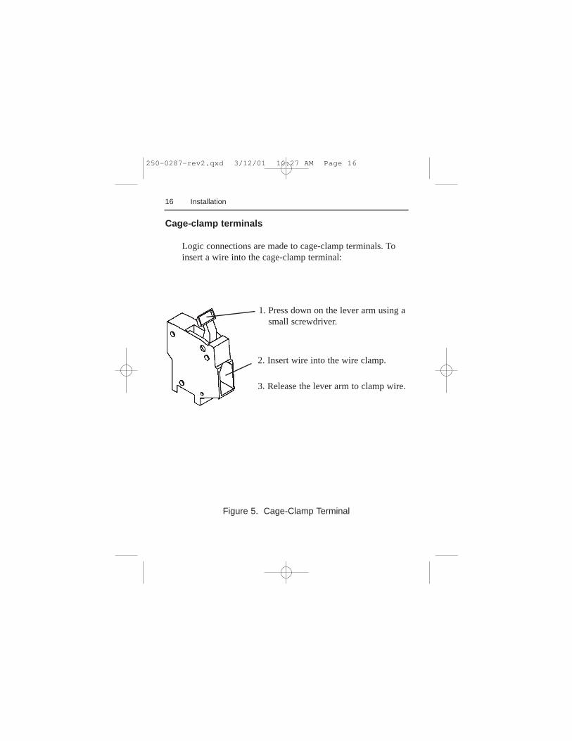
Cage-clamp terminals
Logic connections are made to cage-clamp terminals. Toinsert a wire into the cage-clamp terminal:
Figure 5. Cage-Clamp Terminal
Installation
1. Press down on the lever arm using asmall screwdriver.
2. Insert wire into the wire clamp.
3. Release the lever arm to clamp wire.
250-0287-rev2.qxd 3/12/01 10:27 AM Page 16
17Installation
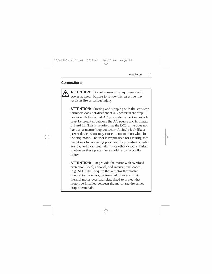
ATTENTION: Do not connect this equipment withpower applied. Failure to follow this directive mayresult in fire or serious injury.
ATTENTION: Starting and stopping with the start/stopterminals does not disconnect AC power in the stopposition. A hardwired AC power disconnection switchmust be mounted between the AC source and terminalsL I and L2. This is required, as the DC3 drive does nothave an armature loop contactor. A single fault like apower device short may cause motor rotation when inthe stop mode. The user is responsible for assuring safeconditions for operating personnel by providing suitableguards, audio or visual alarms, or other devices. Failureto observe these precautions could result in bodilyinjury.
ATTENTION: To provide the motor with overloadprotection, local, national, and international codes(e.g.,NEC/CEC) require that a motor thermostat,internal to the motor, be installed or an electronicthermal motor overload relay, sized to protect themotor, be installed between the motor and the drivesoutput terminals.
Connections
m
250-0287-rev2.qxd 3/12/01 10:27 AM Page 17
18 Installation
ATTENTION: Installation of a master power switch inthe input line is required. This is the only way todisconnect power from the motor. The user isresponsible for assuring safe conditions for operatingpersonnel by providing suitable guards, audio or visualalarms, or other devices. Failure to observe theseprecautions could result in bodily injury.
m
Motor
ATTENTION: To provide the motor with overloadprotection, local, national, and international codes (e.g.,NEC/CEC) require that a motor thermostat, internal tothe motor, be installed or an electronic thermal motoroverload relay, sized to protect the motor, be installedbetween the motor and the drive’s output terminals.
m
IMPORTANT: Reliance Electric drives supply motorvoltage from A1and A2 terminals. It is assumed throughoutthis manual that, when A1 is positive with respect to A2,the motor will rotate clockwise (CW) while looking at theoutput shaft protruding from the front of the motor. If thisis opposite of the desired rotation, simply reverse thewiring of A1 and A2 with each other.
250-0287-rev2.qxd 3/12/01 10:27 AM Page 18
19Installation
Connect a motor to terminals A1 and A2 as shown inFigure 6 (page 23). Ensure that the motor voltage rating isconsistent with the drive’s output voltage.
Power input
ATTENTION: Installation of a master power switch inthe input line is required. This is the only way todisconnect power from the motor. The user isresponsible for assuring safe conditions for operatingpersonnel by providing suitable guards, audio or visualalarms, or other devices. Failure to observe theseprecautions could result in bodily injury.
m
Connect the AC line power leads to terminals L1 and L2 asshown in Figure 6 (page 23). Install a master power switchin the voltage input line, as shown in Figure 6. The switchcontacts should be rated at a minimum of 250 volts and200% of maximum drive current.
250-0287-rev2.qxd 3/12/01 10:27 AM Page 19
20 Installation
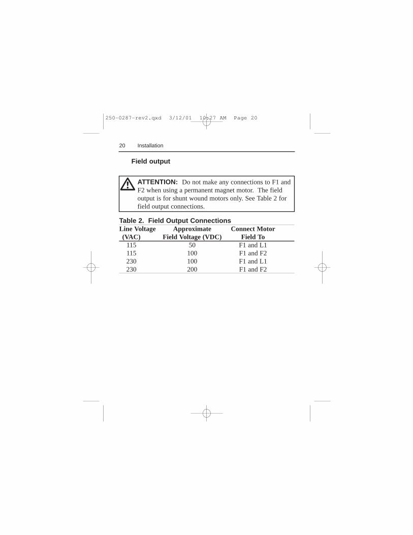
ATTENTION: Do not make any connections to F1 andF2 when using a permanent magnet motor. The fieldoutput is for shunt wound motors only. See Table 2 forfield output connections.
m
Table 2. Field Output ConnectionsLine Voltage Approximate Connect Motor(VAC) Field Voltage (VDC) Field To
115 50 F1 and L1115 100 F1 and F2230 100 F1 and L1230 200 F1 and F2
Field output
250-0287-rev2.qxd 3/12/01 10:27 AM Page 20
21
START/STOP pushbuttons
Installation
Pushbutton operation of the DC3N drive requires that a(momentarily) normally-closed STOP pushbutton be wiredto terminals B2 and B3 and a (momentarily) normally-openSTART pushbutton wired to terminals B1 and B2. Thesepushbuttons must be used together and are not includedwith the drive. The B1, B2 and B3 terminals are onterminal block 502 (TB502).
IMPORTANT: If the START/STOP pushbuttons are notused, wire a jumper between terminals B1 and B3 tobypass the latching circuit. The drive will then operate in apower-up start mode. See Figure 6 (page 23) for theseswitch connections.
ATTENTION: Starting and stopping with the start/stopterminals does not disconnect AC power in the stopposition. A hardwired AC power disconnection switchmust be mounted between the AC source and terminalsL I and L2. This is required, as the DC3 drive does nothave an armature loop contactor. A single fault like apower device short may cause motor rotation when inthe stop mode. The user is responsible for assuring safeconditions for operating personnel by providing suitableguards, audio or visual alarms, or other devices. Failureto observe these precautions could result in bodilyinjury.
m
250-0287-rev2.qxd 3/12/01 10:27 AM Page 21
22 Installation
Using tachometer feedback improves speed regulation fromapproximately 1% of motor base speed to approximately0.1% of motor base speed. Use tachometers rated from 7VDC per 1000 RPM to 50 VDC per 1000 RPM. Connectthe tachometer to terminals T1 and T2 of terminal block502 (TB502). Place switch SW505 in the TACH position.See Figure 6 for tachometer connections.
IMPORTANT: The TACH trimpot must be adjusted priorto operating with tachometer feedback. Refer to theCalibration section (pg 48) for instructions on calibratingthe TACH trimpot.
ATTENTION: Applying the incorrect polarity to thetachometer can cause an overspeed condition. Makesure the positive (+) wire is connected to terminal T1and the negative (-) wire is connect to terminal T2 whenthe motor is running in the forward direction. Failure toobserve this precaution could result in bodily injury.
m
Tachometer feedback
250-0287-rev2.qxd 3/12/01 10:27 AM Page 22
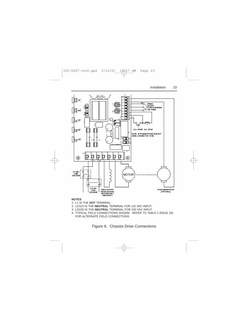
Figure 6. Chassis Drive Connections
23Installation
NOTES1. L1 IS THE HOT TERMINAL.2. L2/115 IS THE NEUTRAL TERMINAL FOR 115 VAC INPUT.3. L2/230 IS THE NEUTRAL TERMINAL FOR 230 VAC INPUT.4. TYPICAL FIELD CONNECTIONS SHOWN. REFER TO TABLE 2 (PAGE 29)
FOR ALTERNATE FIELD CONNECTIONS.
250-0287-rev2.qxd 3/12/01 10:27 AM Page 23
24 Installation
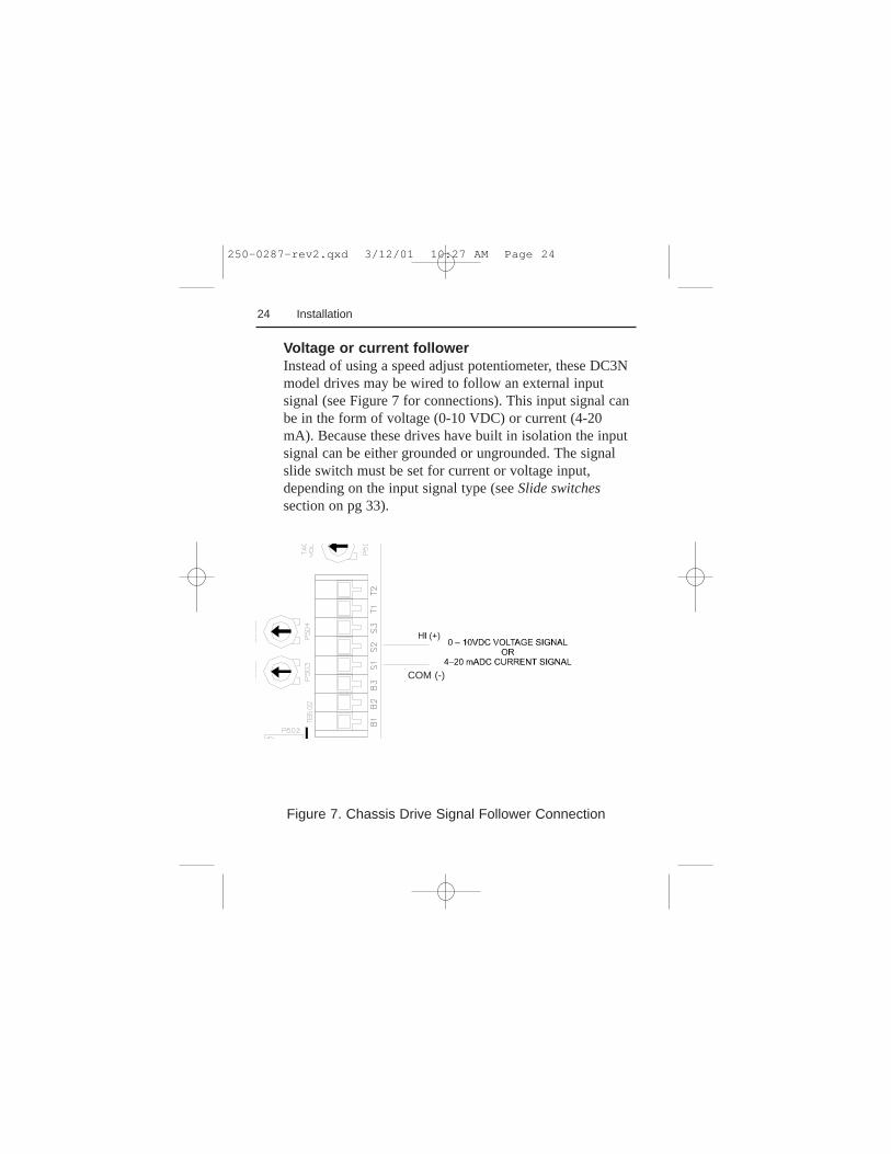
Figure 7. Chassis Drive Signal Follower Connection
Voltage or current followerInstead of using a speed adjust potentiometer, these DC3Nmodel drives may be wired to follow an external inputsignal (see Figure 7 for connections). This input signal canbe in the form of voltage (0-10 VDC) or current (4-20mA). Because these drives have built in isolation the inputsignal can be either grounded or ungrounded. The signalslide switch must be set for current or voltage input,depending on the input signal type (seeSlide switchessection on pg 33).
COM (-)
250-0287-rev2.qxd 3/12/01 10:27 AM Page 24
25
Enclosed drive
Mounting
The NEMA 4X enclosed drive comes with 0.88 inch (22mm) conduit knockout holes at the bottom of theenclosure. The units may be vertically wall mounted usingthe four 0.19 inch (5 mm) slotted holes on the attached heatsink. For motor loads less than 5 ADC, the drive may bebench mounted horizontally, or operated without mounting.
Mount the drive as follows:
1. Install the mounting screws.2. For access to the terminal strip, turn the slotted screw on
the front cover counterclockwise until it is free from theenclosure. The right side of the cover is hinged to theenclosure. Pull the slotted screw to open the enclosure.
3. Carefully remove the conduit knockouts by tapping theminto the enclosure and twisting them off with pliers.
4. Install conduit hardware through the 0.88 inch (22 mm)knockout holes. Connect external wiring to the terminalblock.
5. Grasp the slotted screw and tilt the front cover back intoplace. Avoid pinching any wires between the front coverand the enclosure.
Installation
250-0287-rev2.qxd 3/12/01 10:27 AM Page 25
26
6. Turn the slotted screw clockwise until tight to secure thefront cover.
7. Set the POWER switch to the OFF position beforeapplying the AC line voltage.
Heat sinking
The enclosed DC3N drive contains sufficient heat sinkingin its basic configuration. No additional heat sinking isnecessary when installed in accordance with the guidelinesspecified in this manual.
Line fusing
Installation
ATTENTION: Most code requires that upstreambranch protection be provided to protect input powerwiring. Failure to observe this precaution could result insevere bodily injury or loss of life.
m
This DC3N model has 15-amp line fuses preinstalled onfuse holders 501 and 502 (FU501 and FU502). Whenreplacing the line fuses, use fast acting fuses rated for 250VAC or higher. See Figure 3, page 6, for fuse holderlocation, and Table 1, page 13, for recommended line fusesizes.
250-0287-rev2.qxd 3/12/01 10:27 AM Page 26
27Installation
Connections
ATTENTION: A single fault like a power device shortmay cause motor rotation when in the stop mode. Theuser is responsible for assuring safe conditions foroperating personnel by providing suitable guards, audioor visual alarms, or other devices. Failure to observethese precautions could result in bodily injury.
ATTENTION: To provide the motor with overloadprotection, local, national, and international codes(e.g.,NEC/CEC) require that a motor thermostat,internal to the motor, be installed or an electronicthermal motor overload relay, sized to protect themotor, be installed between the motor and the drivesoutput terminals.
ATTENTION: Do not connect this equipment withpower applied. Failure to observe this precaution mayresult in fire or serious injury.
m
250-0287-rev2.qxd 3/12/01 10:27 AM Page 27
28 Installation
Motor
ATTENTION: To provide the motor with overloadprotection, local, national, and international codes (e.g.,NEC/CEC) require that a motor thermostat, internal tothe motor, be installed or an electronic thermal motoroverload relay, sized to protect the motor, be installedbetween the motor and the drives output terminals.
m
IMPORTANT: Reliance Electric drives supply motorvoltage from A1and A2 terminals. It is assumed throughoutthis manual that, when A1 is positive with respect to A2,the motor will rotate clockwise (CW) while looking at theoutput shaft protruding from the front of the motor. If thisis opposite of the desired rotation, simply reverse thewiring of A1 and A2 with each other.
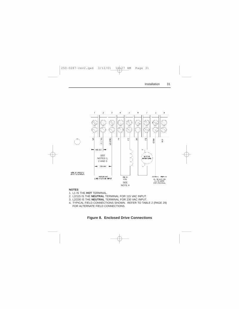
Connect a motor to terminals A1 and A2 as shown inFigure 8 (page 31). Ensure that the motor voltage rating isconsistent with the drive’s output voltage.
250-0287-rev2.qxd 3/12/01 10:27 AM Page 28
29Installation
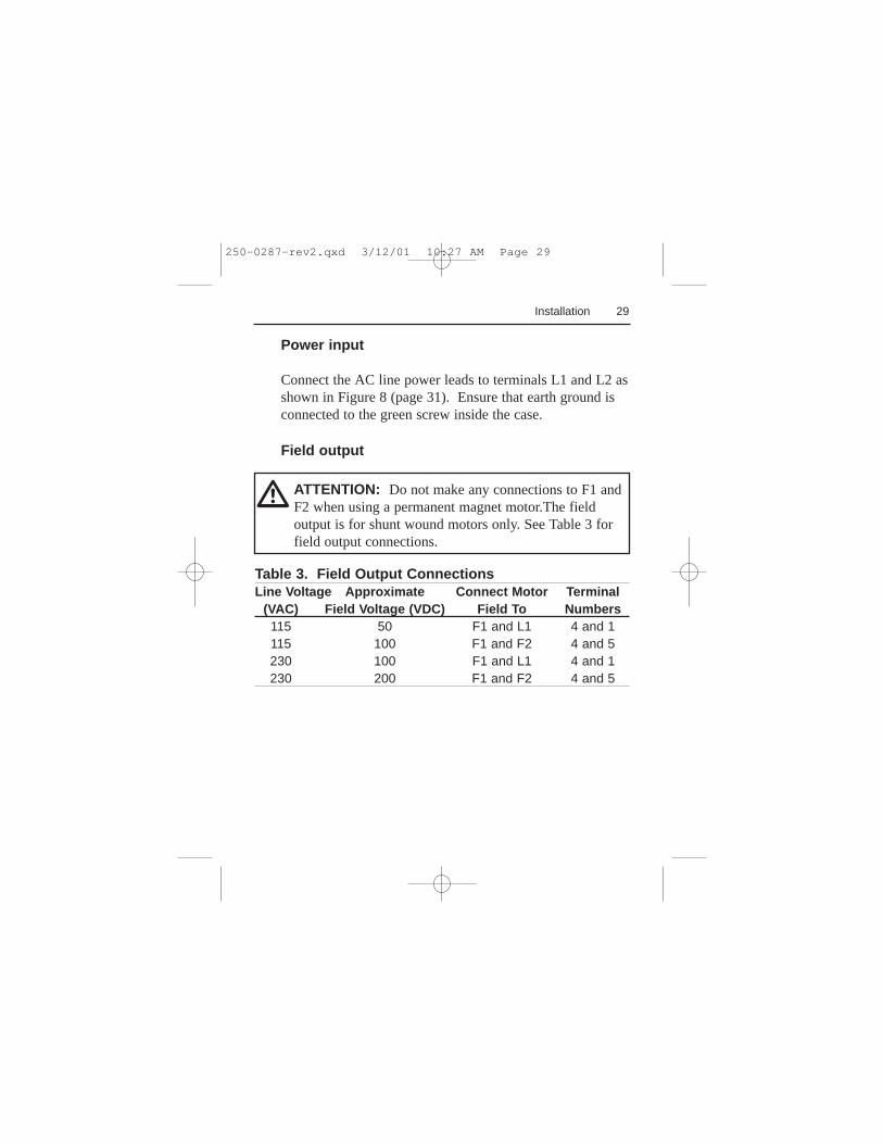
Power input
Connect the AC line power leads to terminals L1 and L2 asshown in Figure 8 (page 31). Ensure that earth ground isconnected to the green screw inside the case.
Field output
ATTENTION: Do not make any connections to F1 andF2 when using a permanent magnet motor.The fieldoutput is for shunt wound motors only. See Table 3 forfield output connections.
m
Table 3. Field Output ConnectionsLine Voltage Approximate Connect Motor Terminal
(VAC) Field Voltage (VDC) Field To Numbers115 50 F1 and L1 4 and 1115 100 F1 and F2 4 and 5230 100 F1 and L1 4 and 1230 200 F1 and F2 4 and 5
250-0287-rev2.qxd 3/12/01 10:27 AM Page 29

30 Installation
Using tachometer feedback improves speed regulation fromapproximately 1% of motor base speed to approximately0.1% of motor base speed. Use tachometers rated from 7VDC per 1000 RPM to 50 VDC per 1000 RPM. Connectthe tachometer to terminals T1 and T2 of terminal block502 (TB502). Place switch SW505 in the TACH position.See Figure 6 (page 23) for tachometer connections.
IMPORTANT: The TACH trimpot must be adjusted priorto operating with tachometer feedback. Refer to theCalibration section (page 48) for instructions on calibratingthe TACH trimpot.
ATTENTION: Applying the incorrect polarity to thetachometer can cause an overspeed condition. Makesure the positive (+) wire is connected to terminal T1and the negative (-) wire is connect to terminal T2 whenthe motor is running in the forward direction. Failure toobserve this precaution could result in bodily injury.
m
Tachometer feedback
250-0287-rev2.qxd 3/12/01 10:27 AM Page 30
31Installation
Figure 8. Enclosed Drive Connections
NOTES1. L1 IS THE HOT TERMINAL.2. L2/115 IS THE NEUTRAL TERMINAL FOR 115 VAC INPUT.3. L2/230 IS THE NEUTRAL TERMINAL FOR 230 VAC INPUT.4. TYPICAL FIELD CONNECTIONS SHOWN. REFER TO TABLE 2 (PAGE 29)
FOR ALTERNATE FIELD CONNECTIONS.
SEENOTE 4
SEENOTES 1,2 AND 3
250-0287-rev2.qxd 3/12/01 10:27 AM Page 31
32 Installation
Voltage or current follower
Instead of using a speed adjust potentiometer, these DC3Nseries drives may be wired to follow an external inputsignal (see Figure 8 on page 31 for connections). This inputsignal can be in the form of voltage (0-10 VDC) or current(4-20 mA). Because these drives have built-in isolation, theinput signal can be either grounded or ungrounded. Thesignal slide switch SW504 must be set for current orvoltage input, depending on the input signal type (seeSlideswitchessection on page 33).
250-0287-rev2.qxd 3/12/01 10:27 AM Page 32
33Installation
Slide switches
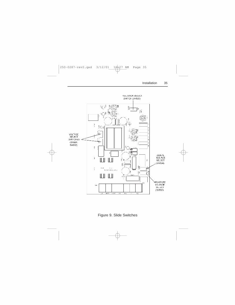
See Figure 9 on page 35 for all slide switch locations.
LINE VOLTAGE (SW501 and SW502)
Select the appropriate line voltage: 115 for 115 VAC linevoltage, or 230 for 230 VAC line voltage.
MOTOR (SW503)
Select the maximum armature voltage: 90V for 90 VDCmotors, or 180V for 180 VDC motors. If the AC linevoltage is 115 VAC, the typical maximum output voltage is90 VDC. If the AC line voltage is 230 VAC, the typicalmaximum output voltage is 180 VDC.
ATTENTION: Change slide switch settings only whenthe drive is disconnected from the AC line voltage.Make sure both line voltage and motor switches are setto their correct position. If the switches are improperlyset to a lower voltage position, the motor will not run atfull voltage and may cause transformer damage. If theswitches are improperly set to a higher voltage position,the motor will overspeed, which may cause motordamage or result in bodily injury or loss of life.
m
250-0287-rev2.qxd 3/12/01 10:27 AM Page 33
34 Installation
ATTENTION: The DC3N does not have tachometerloss or a field loss protection. Loss of field ortachometer will cause the motor to run at maximumuncontrolled speed. The user is responsible for assuringsafe conditions for operating personnel by providingsuitable guards, audio or visual alarms, or other devices.Failure to observe these precautions could result inbodily injury.
m
Select the appropriate feedback option: ARMATURE forarmature feedback, or TACH for tachometer feedback.
SIGNAL (SW504)
Select the input signal being used: CURR for 4-20 mADCcurrent input signal, or VOLT for 0-10 VDC voltage inputsignal or speed adjust potentiometer input.
FEEDBACK (SW505)
250-0287-rev2.qxd 3/12/01 10:27 AM Page 34
35
Figure 9. Slide Switches
Installation
250-0287-rev2.qxd 3/12/01 10:27 AM Page 35
36
Operation
ATTENTION: Change voltage switch settings onlywhen the drive is disconnected from AC line voltage.Make sure both switches are set to their correctposition. If the switches are improperly set to a lowervoltage position, the motor will not run at full voltageand may cause damage to the transformer. If theswitches are improperly set to a higher voltage position,the motor will overspeed, which may cause motordamage, or result in bodily injury or loss of life.
m
ATTENTION: Only qualified technical personnel,familiar with the construction and operation of thisequipment and the hazards involved, should install,adjust, operate and/or service this equipment. Read andunderstand this instruction manual in its entirety beforeproceeding. Failure to observe this precaution couldresult in severe bodily injury or loss of life.
ATTENTION: All adjustments to these componentsshould be made with power removed. Failure toobserve this precaution could result in severe bodilyinjury or loss of life.
m
250-0287-rev2.qxd 3/12/01 10:27 AM Page 36
37Operation
Before applying power (all models)
ATTENTION: If the motor or drive does not performas described, disconnect the AC line voltageimmediately. Refer to theTroubleshootingsection,page 67, for further assistance.
m
• Set LINE VOLTAGE SELECT switches SW501 andSW502 to either 115V or 230V to match the AC linevoltage.
• Set ARMATURE VOLTAGE SELECT switch SW503 toeither 90V or 180V to match the maximum armaturevoltage.
• Set SIGNAL SELECT switch SW504 to CURR if usinga 4-20 mADC current signal; set it to VOLT if using a0-10 VDC voltage signal or the speed adjustpotentiometer.
• Verify that no conductive material is present on theprinted circuit board.
• If using a 90 VDC or 130 VDC motor with 230 VACline voltage, derate the nameplate motor speed andtorque by at least 30%. The form factor will increasebeyond the typical value, causing increased motorheating. Contact the factory for details.
250-0287-rev2.qxd 3/12/01 10:27 AM Page 37
38 Operation
Drive operation
Chassis drive operation
POWER ON start
SPEED REFERENCE: External signal orpotentiometerSTART/STOP control: POWER ON/OFF
IMPORTANT: It is necessary to wire a jumper betweenB1 and B3 if no START/STOP switches are to be used.
IMPORTANT: Line starting and line stopping (applyingand removing AC line voltage) is recommended forinfrequent starting and stopping of a drive only. When ACline voltage is applied to the drive, the motor accelerates tothe speed set by the speed adjust potentiometer or analoginput signal. When AC line voltage is removed, the motorcoasts to a stop.
1. Turn the speed adjust potentiometer fullcounterclockwise (CCW), or set the external referencesignal so that it is at its lowest level (0V or 4 mA).
2. Apply AC line voltage.
250-0287-rev2.qxd 3/12/01 10:27 AM Page 38
39
3. Slowly increase the speed reference signal. The motorslowly accelerates as the potentiometer is turned CWor the external speed reference is increased. Continueuntil the desired speed is reached.
4. Remove AC line voltage to coast the motor to a stop.
Pushbutton start/stop
SPEED REFERENCE: External signal orpotentiometerSTART/STOP control: PUSHBUTTON
ATTENTION: Starting and stopping with the start/stopterminals does not disconnect AC power in the stopposition. A hardwired AC power disconnection switchmust be mounted between the AC source and terminalsL I and L2. This is required, as the DC3 drive does nothave an armature loop contactor. A single fault like apower device short may cause motor rotation when inthe stop mode. The user is responsible for assuring safeconditions for operating personnel by providing suitableguards, audio or visual alarms, or other devices. Failureto observe these precautions could result in bodilyinjury.
m
Operation
1. Turn the speed adjust potentiometer fullcounterclockwise (CCW), or set the external referencesignal so that it is at its lowest level (0 VDC or 4 mA).
250-0287-rev2.qxd 3/12/01 10:27 AM Page 39

2. Apply AC line voltage.3. Slowly increase the speed reference signal and press the
START pushbutton. The motor accelerates as thepotentiometer is turned CW or the external speedreference is increased. Continue until the desired speedis reached.
4. Press STOP pushbutton to coast motor to a stop.
40 Operation
250-0287-rev2.qxd 3/12/01 10:27 AM Page 40
41Operation
Alternate Starting and Stopping Methods
ATTENTION: The DC3 Drive is intended to operateat a predetermined minimum speed. If the applicationrequires zero speed operation, the user is responsible forassuring safe conditions for operating personnel byproviding suitable guards, audio or visual alarms, orother devices. Failure to observe these precautionscould result in bodily injury.
ATTENTION: For frequent starts and stops, usecoasting to a stop with a STOP pushbutton, deceleratingto minimum speed (shorting S2 and S1 to each other),or dynamic braking. Do not use any of these methodsfor emergency stopping. They may not stop a drive thatis malfunctioning. Removing AC line power (both L1and L2) is the only acceptable method for emergencystopping.
ATTENTION: Frequent starts and stops, coasting to astop, decelerating to minimum speed, and dynamicbraking produce high current. This may cause damageto motors, especially gearmotors, that are not properlysized for the application.
m
250-0287-rev2.qxd 3/12/01 10:27 AM Page 41
42 Operation
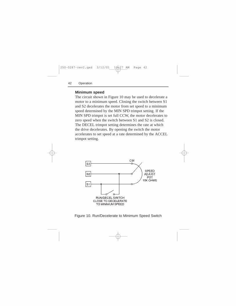
Figure 10. Run/Decelerate to Minimum Speed Switch
Minimum speedThe circuit shown in Figure 10 may be used to decelerate amotor to a minimum speed. Closing the switch between S1and S2 decelerates the motor from set speed to a minimumspeed determined by the MIN SPD trimpot setting. If theMIN SPD trimpot is set full CCW, the motor decelerates tozero speed when the switch between S1 and S2 is closed.The DECEL trimpot setting determines the rate at whichthe drive decelerates. By opening the switch the motoraccelerates to set speed at a rate determined by the ACCELtrimpot setting.
250-0287-rev2.qxd 3/12/01 10:27 AM Page 42
43Operation
Dynamic braking may be used to rapidly stop a motor(Figure 11, page 44). For the RUN/BRAKE switch, use atwo-pole, two-position switch rated for at least 250 VDCand 150% of motor nameplate current. For the dynamicbrake resistor, use a 40-watt minimum, high power,wirewound resistor, or refer toTable 4 on page 44.
Dynamic brake resistor valueSizing the dynamic brake resistor depends on load inertia,motor voltage, and braking time. Use a lower-value,higher-wattage dynamic brake resistor to stop a motormore rapidly. Refer to Table 4 (page 44) for recommendeddynamic brake resistor sizes.
Dynamic braking
ATTENTION: Wait for the motor to completely stopbefore switching it back to RUN. This will prevent higharmature currents from damaging the motor.
ATTENTION: Armature output can drift full ON withthe switch in the BRAKE position and will be drivenfull ON if the minimum speed option is selected withthe inhibit circuit. Failure to observe this precautioncould result in severe bodily injury or loss of life.
m
250-0287-rev2.qxd 3/12/01 10:27 AM Page 43
44 Operation
Figure 11. Dynamic Brake Connection
DC3N DRIVE
Table 4. Minimum Recommended Dynamic BrakeResistor ValuesMotor Armature Minimum MinimumCurrent Rating Dynamic Brake Dynamic BrakeWattage Resistor Value ResistorLess than 2 ADC 1 ohm 1W2–3 ADC 5 ohm 5W3–5 ADC 10 ohm 20W5–10 ADC 20 ohm 40W
250-0287-rev2.qxd 3/12/01 10:27 AM Page 44
45Operation
Enclosed drive operating modes
The mode selector switch on the drive, mounted on itscover, provides the option of operating in either MANUAL(mounted speed potentiometer) or AUTO (external signalsource) mode.
Manual modeSet the mode selector switch to MANUAL if you wish tocontrol the motor speed using the speed adjustpotentiometer mounted on the drive cover. In MANUALmode, the motor speed is controlled by the speed adjustknob located on the drive cover. Setting the speed adjustknob to zero causes the motor to run at the minimum speeddictated by the MIN SPD trimpot setting. Refer to theCalibration section (page 48) for information oncalibrating the MIN SPD trimpot. Set SIGNAL SELECTswitch SW504 to VOLT when in manual mode.
ATTENTION: If you run the drive in AUTO mode, youmust recalibrate the MIN SPD trimpot to offset anymotor drift caused by the input signal. Refer to theCalibration section (page 48) for more information.
m
250-0287-rev2.qxd 3/12/01 10:27 AM Page 45
46 Operation
ATTENTION: For frequent starts and stops, short theinhibit terminals, decelerate to a minimum speed, orapply a dynamic brake to the motor. Do not use any ofthese methods for emergency stopping. They may notstop a drive that is malfunctioning. Removing AC linepower (both L1 and L2) is the only acceptable methodfor emergency stopping.
m
Auto modeIMPORTANT: If you run the drive in AUTO mode usingan external current signal, you must recalibrate the MINSPD trimpot to offset any motor drift caused by the inputsignal.
IMPORTANT: When switching between MANUAL andAUTO (0-10 VDC) modes, you must balance the MINSPD trimpot setting for both operating modes.
Set the mode selector switch to AUTO if you wish tofollow an external signal, independent of the speed adjustknob setting. In AUTO mode, the drive will control motorspeed in proportion to either a 0 – 10 VDCanalog voltageor a 4 – 20mADC current signal. You must set selectswitch SW504, SIGNAL SOURCE SELECT, to eitherVOLTAGE or CURRENT, depending on your signal input.
Enclosed drive operation
250-0287-rev2.qxd 3/12/01 10:27 AM Page 46
47Operation
To run the motor:1. Set the speed adjust potentiometer to “0” (full CCW).2. Apply AC line voltage.3. Set the POWER switch to the ON position.4. Slowly advance the speed adjust potentiometer
clockwise (CW), or increase the external referencesignal. The motor will slowly accelerate to follow thespeed adjust potentiometer or external reference signal.Continue until the desired speed is reached.
To stop the motor:1. Rotate the speed adjust potentiomter to zero (full
CCW), or set the external reference signal to zero.The motor will slowly decelerate until minimum speedis reached.
2. Set the POWER switch on the front panel to OFF.
ATTENTION: Frequent starting and stopping canproduce high torque. This may cause damage to motors,especially gearmotors that are not properly sized for theapplication.
m
250-0287-rev2.qxd 3/12/01 10:27 AM Page 47
48
These DC3N drives have seven user adjustable trimpots.Each drive is factory calibrated to its maximumhorsepower rating.Readjust the calibration trimpotsettings to accommodate lower horsepower motors.
All adjustments increase with CW rotation, and decreasewith CCW rotation. Use a non-metallic screwdriver forcalibration. Each trimpot is identified on the printed circuitboard. Refer to Figure 12 for trimpot locations.
Calibration
ATTENTION: Dangerous voltages exist on the drivewhen it is powered, and up to 30 seconds after power isremoved and the motor stops. When possible,disconnect the voltage input from the drive beforeadjusting the trimpots. If the trimpots must be adjustedwith power applied, use insulated tools and theappropriate personal protection equipment. BE ALERT.High voltages can cause serious or fatal injury.
ATTENTION: The control circuit is at line potentialwhen the drive is energized. Exercise extreme cautionas hazardous voltage exists.
m
250-0287-rev2.qxd 3/12/01 10:27 AM Page 48
49Calibration
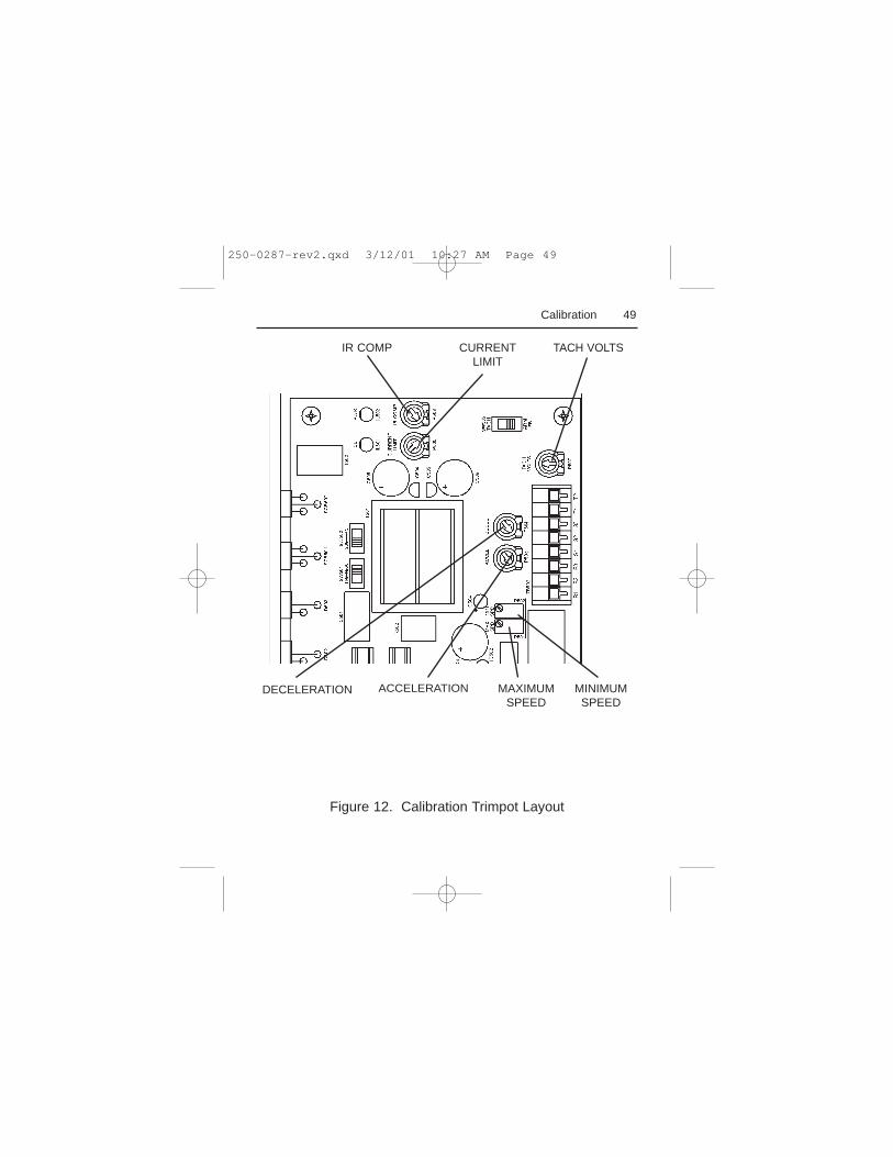
Figure 12. Calibration Trimpot Layout
CURRENTLIMIT
IR COMP TACH VOLTS
MAXIMUMSPEED
MINIMUMSPEED
ACCELERATIONDECELERATION
250-0287-rev2.qxd 3/12/01 10:27 AM Page 49
Drive Calibration Procedure
Prepare the DC3N drive for calibration as follows. Thisprocedure applies to both chassis and enclosed drives.
1. Ensure that no power is applied to the drive.2. If you use an enclosed drive, you must open the drive
cover to gain access to the trimpots. Turn the slottedscrew on the front cover counterclockwise until it isfree from the enclosure. The right side of the cover ishinged to the enclosure. Pull the slotted screw to openthe enclosure.
3. Set all trimpots except CURRENT LIMIT and TACHVOLTS full counterclockwise (CCW).
4. Set the CURRENT LIMIT trimpot full clockwise(CW).
5. Make no adjustment to the TACH VOLTS trimpotunless tachometer feedback is used. If you usetachometer feedback, set the TACH VOLTS trimpotto the center of travel (12 o’clock position).
6. Adjust the trimpots in the following order:• MIN SPD• MAX SPD• CURRENT LIMIT• IR COMP• ACCEL• DECEL• TACH VOLTS (if used)
50 Calibration
250-0287-rev2.qxd 3/12/01 10:27 AM Page 50
51
IMPORTANT: If you run the drive in AUTO mode, youmust recalibrate the MIN SPD trimpot to offset any motordrift caused by the input signal.
The MIN SPD setting determines the motor speed whenthe speed adjust potentiometer or input signal is set forminimum speed. It is factory set to zero speed.
To calibrate MIN SPD:1. Turn the speed adjust potentiometer full CCW or set the
external reference signal for minimum voltage orcurrent.
2. Adjust the MIN SPD trimpot until the motor hasstopped, or is running at the desired minimum speed.
Calibration
MIN SPD
ATTENTION: The DC3N Drive is intended to operateat a predetermined minimum speed. If the applicationrequires zero speed operation, the user is responsible forassuring safe conditions for operating personnel byproviding suitable guards, audio or visual alarms, orother devices. Failure to observe these precautionscould result in bodily injury.
m
250-0287-rev2.qxd 3/12/01 10:27 AM Page 51
52 Calibration
MAX SPD
The MAX SPD setting determines the motor speed whenthe speed adjust potentiometer or external reference signalis set for maximum speed. It is factory set for maximumrated motor speed.
To calibrate MAX SPD:1. Set the MAX SPD trimpot full CCW.2. Turn the speed adjust potentiometer full CW or set the
external reference signal for maximum speed.3. Adjust the MAX SPD trimpot until the desired
maximum motor speed is reached.
IMPORTANT: Check the MIN SPD and MAX SPDsettings after recalibrating to verify that the motor runs atthe desired minimum and maximum speeds.
IMPORTANT: If operation requires switching betweenAUTO and MANUAL modes, the user should verifycalibration for both modes if required.
250-0287-rev2.qxd 3/12/01 10:27 AM Page 52
53Calibration
CURRENT LIMIT
ATTENTION: Although the CURRENT LIMITtrimpot is set to 120% of the maximum drive currentrating, continuous operation at that rating may damagethe drive or motor.
m
The CURRENT LIMIT setting determines the maximumarmature current output of the drive. It is factory set at120% of maximum drive current. If you use a lowerhorsepower motor, CURRENT LIMIT must be recalibratedfor the motor.
To calibrate CURRENT LIMIT, refer to Figure 13 onpage 59, or use the following procedure:1. With the power disconnected from the drive, connect a
DC ammeter in series with the armature.2. Set the CURRENT LIMIT trimpot to minimum (full
CCW).3. Lock the motor armature shaft. Be sure that the motor is
firmly mounted in order to withstand torque generatedby the motor.
4. Connect power to the drive. The motor should remainstopped.
5. Set the speed adjust potentiometer or external referencesignal for maximum speed.
250-0287-rev2.qxd 3/12/01 10:27 AM Page 53
6. Adjust the CURRENT LIMIT trimpot slowly CW untilthe armature current is 120% of motor rated current.
7. Set the speed adjust potentiometer or external referencesignal for zero speed and remove power.
8. Remove the lock on the motor armature shaft.
IR COMP
The IR COMP setting determines the degree to whichmotor speed is held constant as the motor load changes. Itis factory set at optimum motor regulation for the highestmotor horsepower.
To calibrate IR COMP, refer to Figure 13 on page 59, oruse the following procedure:1. Turn the IR COMP trimpot full CCW.2. Set the speed adjust potentiometer or external reference
signal until the motor runs at midspeed without load(for example, 900 RPM for an 1800 RPM motor). Ahand held tachometer may be used to measure motorspeed.
3. Load the motor armature to its full load armaturecurrent rating. The motor should slow down.
4. While keeping the load on the motor, rotate the IRCOMP trimpot until the motor runs at the speedmeasured in step 2.
54 Calibration
250-0287-rev2.qxd 3/12/01 10:27 AM Page 54
55Calibration
Approximate IR COMP calibration:If the motor does not maintain set speed as the loadchanges, gradually rotate the IR COMP trimpot CW. If themotor oscillates (overcompensation), the IR COMP trimpotmay be set too high (CW). Turn the IR COMP trimpotCCW to stabilize the motor speed.
ACCEL
The ACCEL setting determines the time the motor takes toramp to a higher speed, within the limits of availabletorque. The ACCEL setting is factory set for its fastestacceleration time (full CCW).
To calibrate ACCEL:1. Set the speed adjust potentiometer or external reference
signal for minimum speed. The motor should run atminimum speed.
2. Set the speed adjust potentiometer or external referencesignal to maximum speed, and measure the time it takesthe motor to go from minimum to maximum speed.
3. If the time measured in step 2 is not the desiredacceleration time, turn the ACCEL trimpot CW for aslower acceleration time, or CCW for a fasteracceleration time. Repeat steps 1 through 3 until theacceleration time is correct.
250-0287-rev2.qxd 3/12/01 10:27 AM Page 55
DECEL
The DECEL setting determines the time the motor takes toramp to lower speed, within the limits of available torque.The DECEL setting is factory set for its fastest decelerationtime (full CCW).
To calibrate DECEL:1. Set the speed adjust potentiometer or external reference
signal for maximum speed. The motor should run atmaximum speed.
2. Set the speed adjust potentiometer or external referencesignal for minimum speed and measure the time it takesthe motor to go from maximum to minimum speed.
3. If the time measured in step 2 is not the desireddeceleration time, turn the DECEL trimpot CW for aslower deceleration time, or CCW for a fasterdeceleration time.
Repeat steps 1 through 3 until the deceleration time iscorrect.
56 Calibration
250-0287-rev2.qxd 3/12/01 10:27 AM Page 56
57Calibration
IMPORTANT: Calibrate the TACH VOLTS setting onlywhen a tachometer is used. The TACH VOLTS setting, likethe IR COMP setting, determines the degree to which themotor speed is held constant as the motor load changes.
To calibrate the TACH VOLTS trimpot:1. Disconnect power from drive.2. Connect the tachometer to T1 and T2. The polarity
is (+) for T1 and (-) for T2 when the motor is running inthe forward direction.
TACH VOLTS
ATTENTION: Applying the incorrect polarity to thetachometer can cause an overspeed condition. Makesure the positive (+) wire is connected to terminal T1and the negative (-) wire is connect to terminal T2 whenthe motor is running in the forward direction. Failure toobserve this precaution could result in bodily injury.
ATTENTION: The control circuit is at line potentialwhen the drive is energized. Use a non-metallicscrewdriver when making adjustments to the circuitboard potentiometers. Exercise extreme caution ashazardous voltage exists. Failure to observe theseprecautions could result in severe bodily injury or lossof life.
m
250-0287-rev2.qxd 3/12/01 10:27 AM Page 57

3. Set switch 505 (SW505) to ARM for armaturefeedback.
4. Apply power to drive.5. Set the speed adjust potentiometer or external
reference signal to maximum speed.6. Measure the armature voltage across A1 and A2 using
a voltmeter.7. Disconnect power from drive.8. Set the speed adjust potentiometer or external
reference signal to minimum speed.9. Set SW505 to TACH for tachometer feedback.10. Set the IR COMP trimpot full CCW.11. Set the TACH VOLTS trimpot full CW.12. Apply power to drive.13. Set the speed adjust potentiometer or external
reference signal to maximum speed.14. Adjust the TACH VOLTS trimpot until the armature
voltage is the same value as the voltage measured instep 6.
Check that the TACH VOLTS trimpot is properlycalibrated. The motor should run at the same set speedwhen SW505 is set to either armature or tachometerfeedback.
58 Calibration
250-0287-rev2.qxd 3/12/01 10:27 AM Page 58
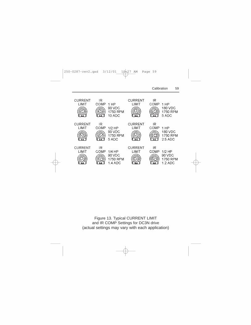
59Calibration
Figure 13. Typical CURRENT LIMITand IR COMP Settings for DC3N drive
(actual settings may vary with each application)
250-0287-rev2.qxd 3/12/01 10:27 AM Page 59
60
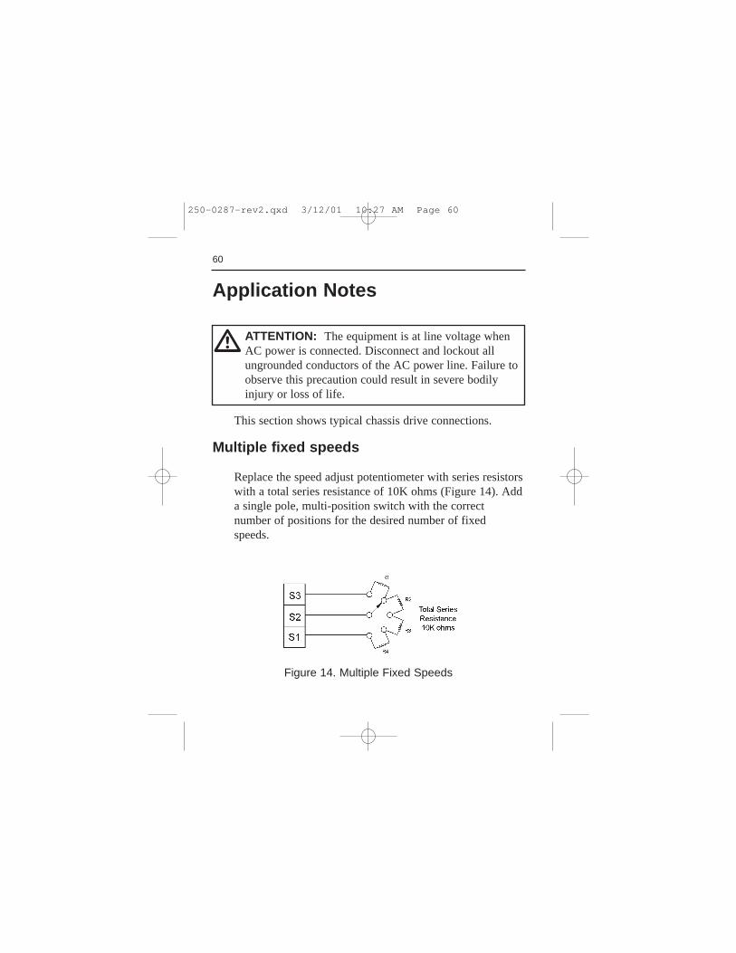
This section shows typical chassis drive connections.
Multiple fixed speeds
Replace the speed adjust potentiometer with series resistorswith a total series resistance of 10K ohms (Figure 14). Adda single pole, multi-position switch with the correctnumber of positions for the desired number of fixedspeeds.
Application Notes
Figure 14. Multiple Fixed Speeds
ATTENTION: The equipment is at line voltage whenAC power is connected. Disconnect and lockout allungrounded conductors of the AC power line. Failure toobserve this precaution could result in severe bodilyinjury or loss of life.
m
250-0287-rev2.qxd 3/12/01 10:27 AM Page 60
61Application Notes
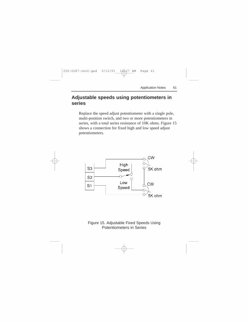
Figure 15. Adjustable Fixed Speeds UsingPotentiometers in Series
Adjustable speeds using potentiometers inseries
Replace the speed adjust potentiometer with a single pole,multi-position switch, and two or more potentiometers inseries, with a total series resistance of 10K ohms. Figure 15shows a connection for fixed high and low speed adjustpotentiometers.
250-0287-rev2.qxd 3/12/01 10:27 AM Page 61
62 Application Notes
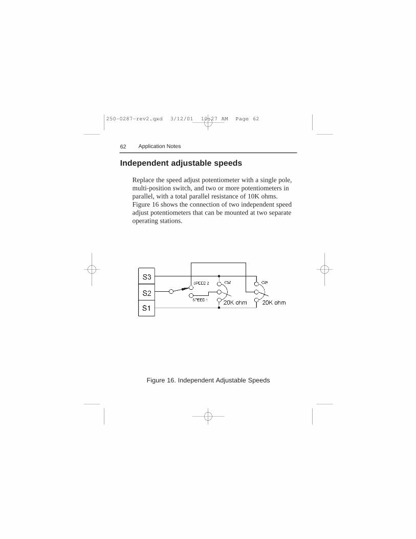
Independent adjustable speeds
Replace the speed adjust potentiometer with a single pole,multi-position switch, and two or more potentiometers inparallel, with a total parallel resistance of 10K ohms.Figure 16 shows the connection of two independent speedadjust potentiometers that can be mounted at two separateoperating stations.
Figure 16. Independent Adjustable Speeds
250-0287-rev2.qxd 3/12/01 10:27 AM Page 62
63Application Notes
ATTENTION: The DC3 Drive is intended to operateat a predetermined minimum speed. If the applicationrequires zero speed operation, the user is responsible forassuring safe conditions for operating personnel byproviding suitable guards, audio or visual alarms, orother devices. Failure to observe these precautionscould result in bodily injury.
m
Reversing
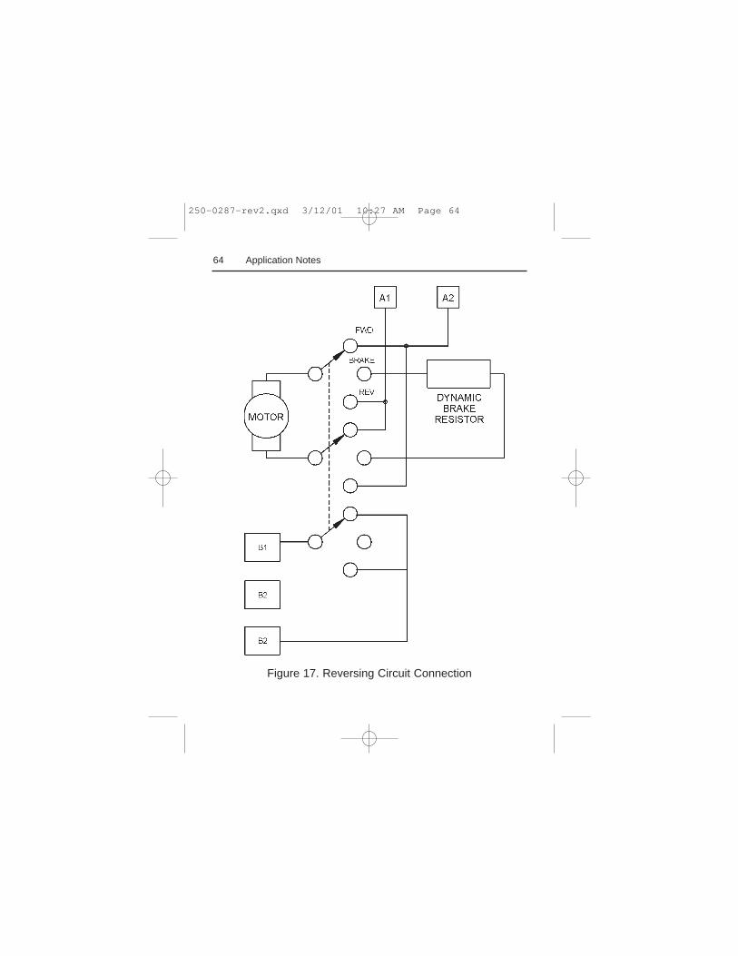
A dynamic brake may be used when reversing the motordirection (Figure 17, page 64). Use a three-pole, three-position switch rated for at least the maximum DCarmature voltage and maximum braking current. Wait forthe motor to stop completely before switching it to eitherthe forward or reverse direction. See theDynamic Brakingsection on page 43 for sizing the dynamic brake resistor.
250-0287-rev2.qxd 3/12/01 10:27 AM Page 63
64 Application Notes
Figure 17. Reversing Circuit Connection
250-0287-rev2.qxd 3/12/01 10:27 AM Page 64
65Application Notes
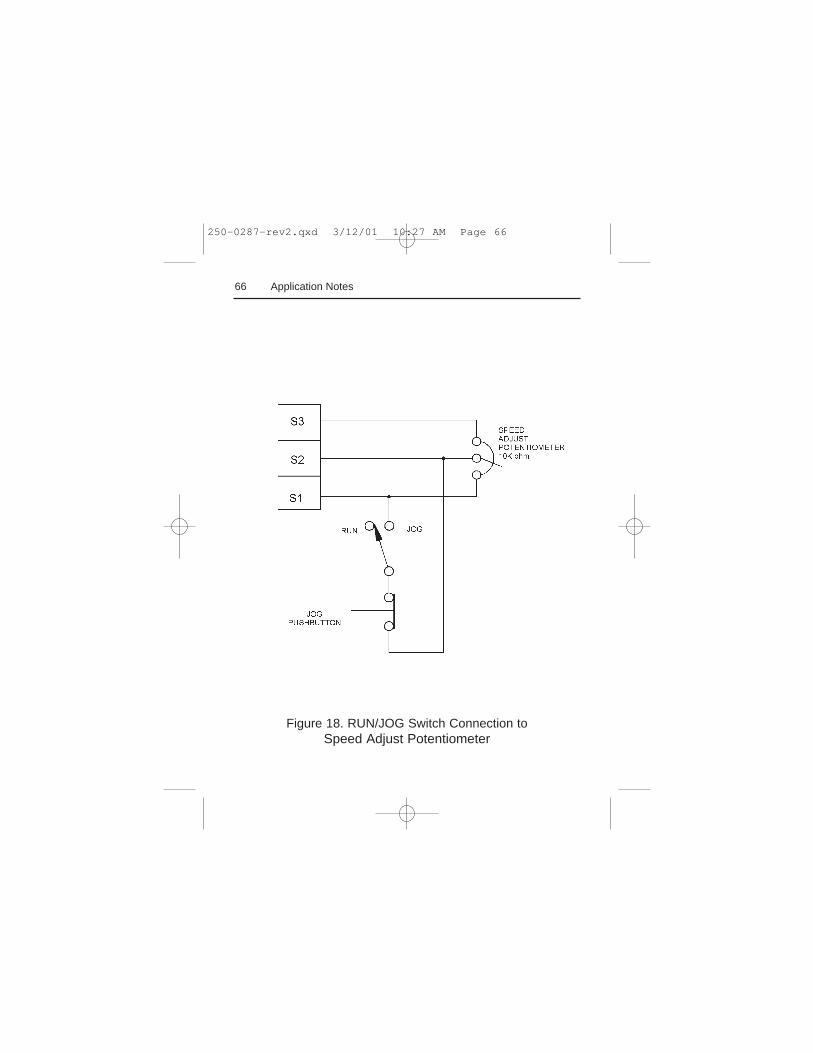
RUN/JOG switch
Using a RUN/JOG switch is recommended in applicationswhere quick stopping is not needed and frequent jogging isrequired. Use a single pole, two position switch for theRUN/JOG switch, and a single pole, normally closed,momentary operated pushbutton for the JOG pushbutton.
Connect the RUN/JOG switch and the JOG pushbutton asshown in Figure 18, page 66. When the RUN/JOG switchis set to JOG, the motor decelerates to minimum speed(minimum speed is determined by the minimum speedtrimpot setting). Press the JOG pushbutton to jog themotor. Return the RUN/JOG switch to RUN for normaloperation.
ATTENTION: Starting and stopping with the start/stopterminals does not disconnect AC power in the stopposition. A hardwired AC power disconnection switchmust be mounted between the AC source and terminalsL I and L2. This is required, as the DC3 drive does nothave an armature loop contactor. A single fault like apower device short may cause motor rotation when inthe stop mode. The user is responsible for assuring safeconditions for operating personnel by providing suitableguards, audio or visual alarms, or other devices. Failureto observe these precautions could result in bodilyinjury.
m
250-0287-rev2.qxd 3/12/01 10:27 AM Page 65
66 Application Notes
Figure 18. RUN/JOG Switch Connection toSpeed Adjust Potentiometer
250-0287-rev2.qxd 3/12/01 10:27 AM Page 66
67
Troubleshooting
Before troubleshooting
Perform the following steps before starting any procedurein this section:
• Disconnect AC line voltage from the drive.• Check the drive closely for damaged components.• Check that no conductive or other foreign material has
become lodged on the printed circuit board.• Verify that every connection is correct and in good
condition.• Verify that there are no short circuits or grounded
connections.• Check that the voltage selection switch settings match
the AC line and output voltages.• Check that the drive’s rated armature and field outputs
are consistent with the motor ratings.• Check that the line fuses are properly sized and not
blown.
ATTENTION: This equipment is at line voltage whenAC power is connected. Disconnect and lockout allungrounded conductors of the AC power line beforeworking on the unit. Failure to observe this precautioncould result in severe bodily injury or loss of life.
m
250-0287-rev2.qxd 3/12/01 10:27 AM Page 67
68 Troubleshooting
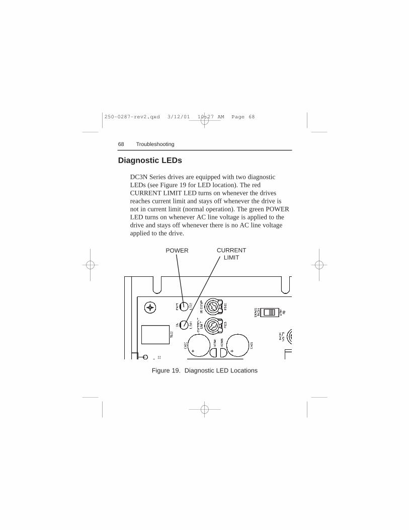
Figure 19. Diagnostic LED Locations
Diagnostic LEDs
DC3N Series drives are equipped with two diagnosticLEDs (see Figure 19 for LED location). The redCURRENT LIMIT LED turns on whenever the drivesreaches current limit and stays off whenever the drive isnot in current limit (normal operation). The green POWERLED turns on whenever AC line voltage is applied to thedrive and stays off whenever there is no AC line voltageapplied to the drive.
CURRENTLIMIT
POWER
250-0287-rev2.qxd 3/12/01 10:27 AM Page 68
69
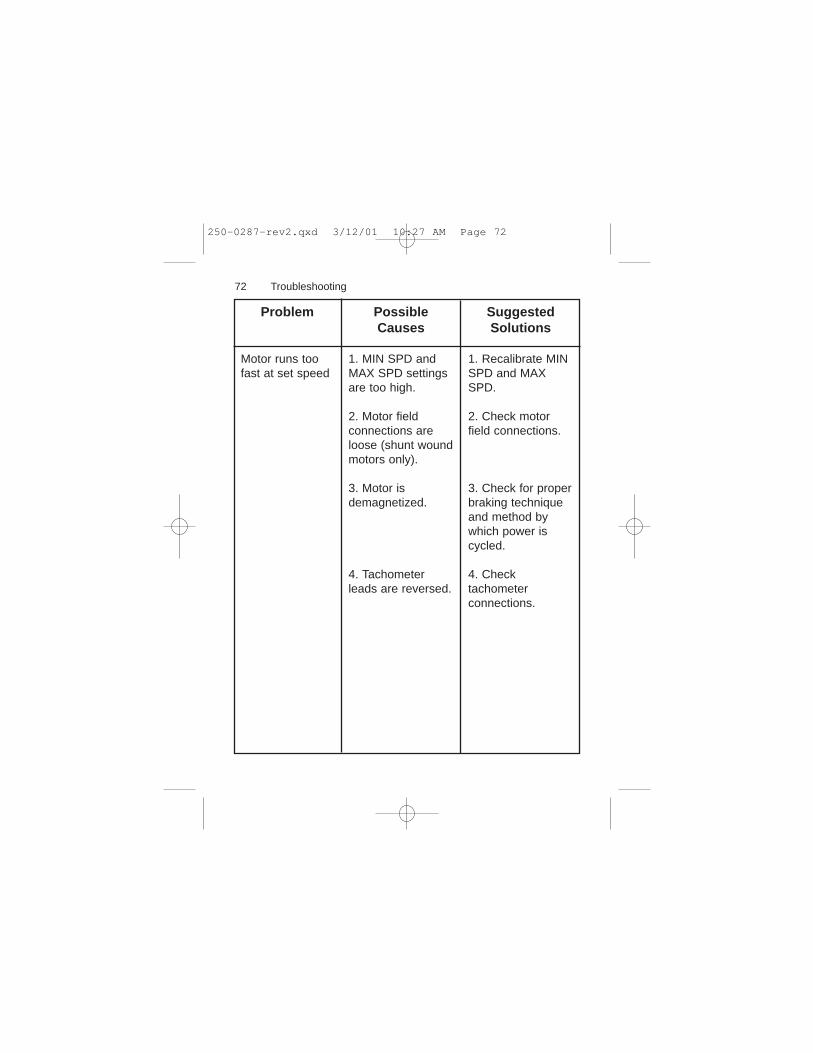
Problem PossibleCauses
SuggestedSolutions
Troubleshooting
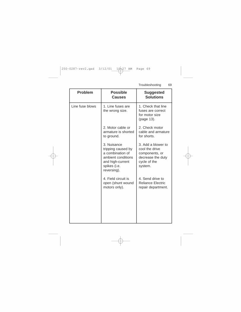
Line fuse blows 1. Line fuses arethe wrong size.
2. Motor cable orarmature is shortedto ground.
3. Nuisancetripping caused bya combination ofambient conditionsand high-currentspikes (i.e.reversing).
4. Field circuit isopen (shunt woundmotors only).
1. Check that linefuses are correctfor motor size(page 13).
2. Check motorcable and armaturefor shorts.
3. Add a blower tocool the drivecomponents, ordecrease the dutycycle of thesystem.
4. Send drive toReliance Electricrepair department.
250-0287-rev2.qxd 3/12/01 10:27 AM Page 69
70
Problem PossibleCauses
SuggestedSolutions
Troubleshooting
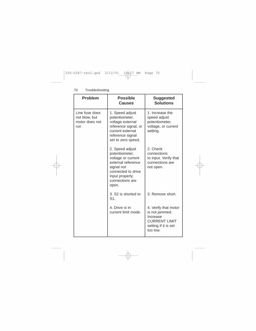
Line fuse doesnot blow, butmotor does notrun
1. Speed adjustpotentiometer,voltage externalreference signal, orcurrent externalreference signalset to zero speed.
2. Speed adjustpotentiometer,voltage or currentexternal referencesignal notconnected to driveinput properly;connections areopen.
3. S2 is shorted toS1.
4. Drive is incurrent limit mode.
1. Increase thespeed adjustpotentiometer,voltage, or currentsetting.
2. Checkconnectionsto input. Verify thatconnections arenot open.
3. Remove short.
4. Verify that motoris not jammed.IncreaseCURRENT LIMITsetting if it is settoo low.
250-0287-rev2.qxd 3/12/01 10:27 AM Page 70
71
Problem PossibleCauses
SuggestedSolutions
Troubleshooting
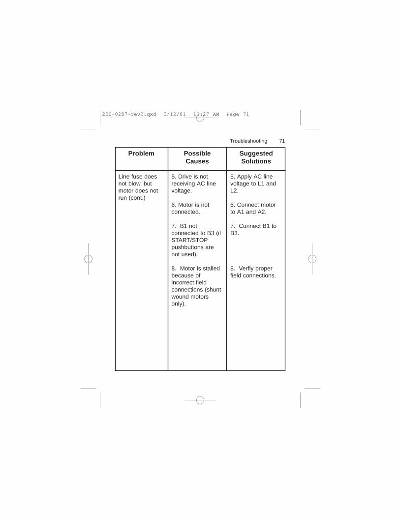
Line fuse doesnot blow, butmotor does notrun (cont.)
5. Drive is notreceiving AC linevoltage.
6. Motor is notconnected.
7. B1 notconnected to B3 (ifSTART/STOPpushbuttons arenot used).
8. Motor is stalledbecause ofincorrect fieldconnections (shuntwound motorsonly).
5. Apply AC linevoltage to L1 andL2.
6. Connect motorto A1 and A2.
7. Connect B1 toB3.
8. Verfiy properfield connections.
250-0287-rev2.qxd 3/12/01 10:27 AM Page 71
72
Problem PossibleCauses
SuggestedSolutions
Troubleshooting
Motor runs toofast at set speed
1. MIN SPD andMAX SPD settingsare too high.
2. Motor fieldconnections areloose (shunt woundmotors only).
3. Motor isdemagnetized.
4. Tachometerleads are reversed.
1. Recalibrate MINSPD and MAXSPD.
2. Check motorfield connections.
3. Check for properbraking techniqueand method bywhich power iscycled.
4. Checktachometerconnections.
250-0287-rev2.qxd 3/12/01 10:27 AM Page 72
73
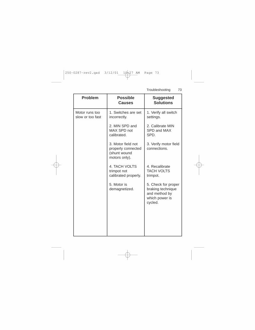
Problem PossibleCauses
SuggestedSolutions
Troubleshooting
Motor runs tooslow or too fast
1. Switches are setincorrectly.
2. MIN SPD andMAX SPD notcalibrated.
3. Motor field notproperly connected(shunt woundmotors only).
4. TACH VOLTStrimpot notcalibrated properly.
5. Motor isdemagnetized.
1. Verify all switchsettings.
2. Calibrate MINSPD and MAXSPD.
3. Verify motor fieldconnections.
4. RecalibrateTACH VOLTStrimpot.
5. Check for properbraking techniqueand method bywhich power iscycled.
250-0287-rev2.qxd 3/12/01 10:27 AM Page 73
74
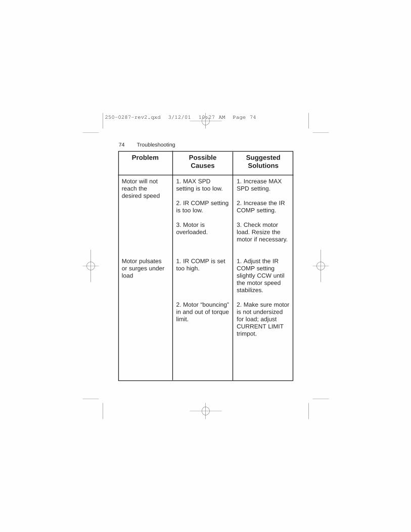
Problem PossibleCauses
SuggestedSolutions
Troubleshooting
Motor will notreach thedesired speed
Motor pulsatesor surges underload
1. MAX SPDsetting is too low.
2. IR COMP settingis too low.
3. Motor isoverloaded.
1. IR COMP is settoo high.
2. Motor “bouncing”in and out of torquelimit.
1. Increase MAXSPD setting.
2. Increase the IRCOMP setting.
3. Check motorload. Resize themotor if necessary.
1. Adjust the IRCOMP settingslightly CCW untilthe motor speedstabilizes.
2. Make sure motoris not undersizedfor load; adjustCURRENT LIMITtrimpot.
250-0287-rev2.qxd 3/12/01 10:27 AM Page 74
75Troubleshooting
Fig
ure
20.
DC
3NB
lock
Dia
gram
Block Diagram
250-0287-rev2.qxd 3/12/01 10:27 AM Page 75

Terminal descriptions
Chassis drive terminals
L1 (TB501)Hot terminal for AC line voltage.
L2/115 (TB501)Neutral terminal for 115 VAC line voltage.
L2/230 (TB501)Neutral terminal for 230 VAC line voltage.
F1, F2 (TB501)Field coil connections (shunt wound motors only). Fieldvoltage is 100/200 VDC.
A1, A2 (TB501)Connections to motor.
B1, B2, B3 (TB502)Connections for START/STOP pushbuttons.
S1, S2, S3 (TB502)Connections for speed adjust potentiometer or externalreference signal.
76 Troubleshooting
250-0287-rev2.qxd 3/12/01 10:27 AM Page 76

T1, T2 (TB502)Connections to optional external tachometer.
Enclosed drive terminals
L1 (terminal 1)Hot terminal for AC line voltage.
L2/115 (terminal 2)Neutral terminal for 115 VAC line voltage.
L2/230 (terminal 3)Neutral terminal for 230 VAC line voltage.
F1, F2 (terminals 4 and 5)Field coil connections (shunt wound motors only). Fieldvoltage is 100/200 VDC.
A1, A2 (terminals 6 and 7)Connections to motor.
COM (terminal 8)Circuit common (-) for external reference signal.
REF (terminal 9)Signal (+) lead for external reference signal.
77Troubleshooting
250-0287-rev2.qxd 3/12/01 10:27 AM Page 77
Reliance Electric Corporation hereby certifies that itsDC3N series drives have been approved to bear the “CE”mark provided the conditions of approval (listed in Exhibit“A”) have been met by the end user.
The DC3N series has been tested to the following testspecifications:
EN55011:1991 (emissions),EN50082-1:1992 (immunity)
Compliance allows Reliance Electric’s DC3N series to bearthe CE mark.
The end user, as described herein, falls into one of twocategories:
1. The Consumer will deploy a stand-alone unit as anintegral, yet external, portion of the machine he/sheis operating.
2. The Original Equipment Manufacturer (OEM) willimplement the product as a component of themachine being manufactured.
78
CE Compliance
250-0287-rev2.qxd 3/12/01 10:27 AM Page 78
79CECompliance
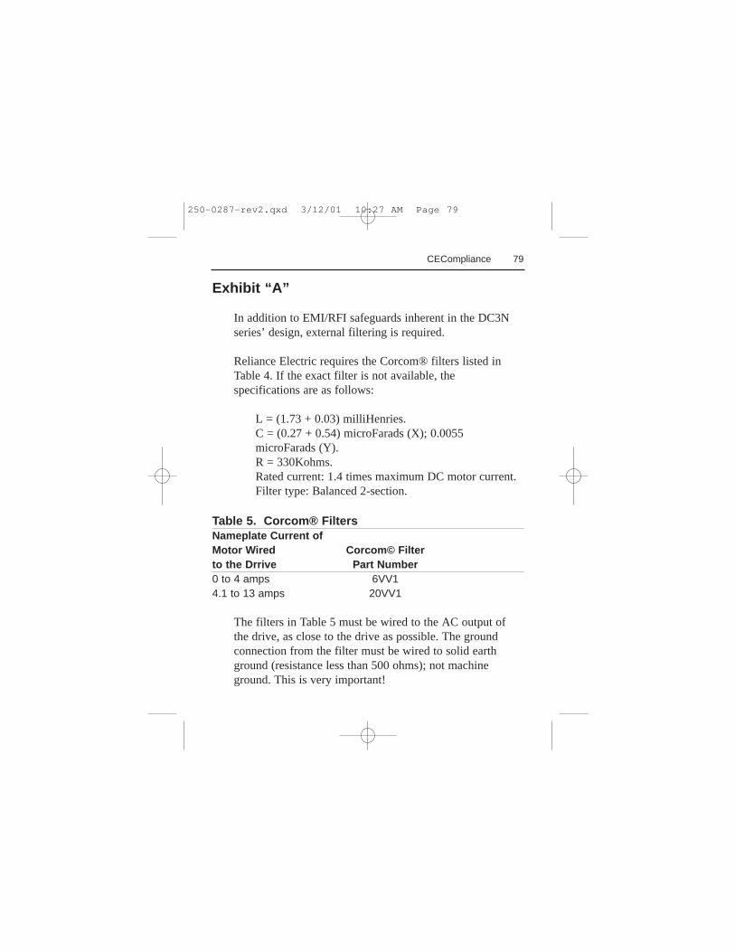
Exhibit “A”
In addition to EMI/RFI safeguards inherent in the DC3Nseries’ design, external filtering is required.
Reliance Electric requires the Corcom® filters listed inTable 4. If the exact filter is not available, thespecifications are as follows:
L = (1.73 + 0.03) milliHenries.C = (0.27 + 0.54) microFarads (X); 0.0055microFarads (Y).R = 330Kohms.Rated current: 1.4 times maximum DC motor current.Filter type: Balanced 2-section.
Table 5. Corcom® FiltersNameplate Current ofMotor Wired Corcom© Filterto the Drrive Part Number0 to 4 amps 6VV14.1 to 13 amps 20VV1
The filters in Table 5 must be wired to the AC output ofthe drive, as close to the drive as possible. The groundconnection from the filter must be wired to solid earthground (resistance less than 500 ohms); not machineground. This is very important!
250-0287-rev2.qxd 3/12/01 10:27 AM Page 79

80 CE Compliance
If the end-user is using a CE-approved motor, the correctfilter from Table 5 is all that is necessary to meet the EMCdirectives listed herein.
Armature Filters
If the end-user is not using a CE-approved motor, aReliance Electric CEXXMM filter must be deployed on theoutput. XX is the rated current on the filter
The CE20MM is a Real-Pole Balanced-Pi 3-pole filter. Ifthe exact filter is not available, the specifications are asfollows:
L & L1 = 2 * (0.8) milliHenries.C & C1 = 2 * (0.1) microFarads @ 400W VDC.Rin = 0.1 ohm; Rout = 1.2 ohm.
Table 6. Armature FiltersNameplate Current ofMotor Wired Reliance Electric© Filterto the Drrive Part Number0 to 4 amps CE04MM4.1 to 13 amps CE20MM
250-0287-rev2.qxd 3/12/01 10:27 AM Page 80
The filters in Table 6 must be wired to the DC output ofthe drive, as close to the drive as possible. The groundconnection from the filter must be wired to solid earthground (resistance less than 500 ohms); not machineground. This is very important!
The end user must use the filtering listed in Exhibit A tocomply with CE. The OEM may choose to providealternative filtering that encompasses the Reliance Electricdrive and other electronics within the same panel.
The OEM has this liberty because CE is a machinerydirective. Whether or not every component in the OEM’smachinery meets CE, the OEM must still submit hismachine for CE approval. Thus, no component mustnecessarily meet CE within the machine, as long as theOEM takes the necessary steps to guarantee the machinedoes meet CE. By the same token, even if everycomponent in the OEM’s machine does meet CE, themachine will not necessarily meet CE as a machine.
Use of CE-approved wiring practices, such as propershielding, and the filters listed in Exhibit A guarantee thedrive will meet EN55011 (1991 emissions standard) andEN50082-1 (1992 immunity standard).
81CE Compliance
250-0287-rev2.qxd 3/12/01 10:27 AM Page 81

Notes
250-0287-rev2.qxd 3/12/01 10:27 AM Page 82

250-0287-rev2.qxd 3/12/01 10:27 AM Page 83

U.S. Drives Technical Support Tel: (1) 262.512.8176, Fax: (1) 262.512.2222, Email: [email protected], Online: www.ab.com/support/abdrives
Publication D2-3452-March 2001 Copyright © 2001 Rockwell Automation, Inc. All Rights Reserved. Printed in USA.