Embed Size (px)
Citation preview
1
DC Machinessecond year
University of Technology
Control and Systems Engineering Department
2
References
Theraja Bl, Theraja Ak “Electrical
Technology”.
V.k mehta “Principles of Electrical Machines’’
E. Hughes “Electrical Technology”
3
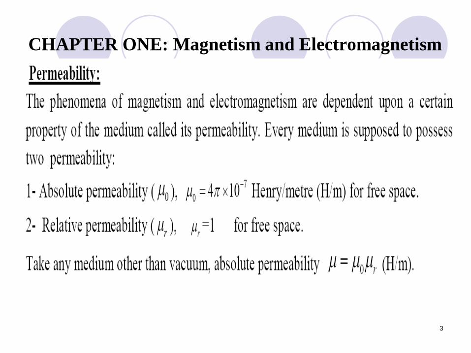
CHAPTER ONE: Magnetism and Electromagnetism
4
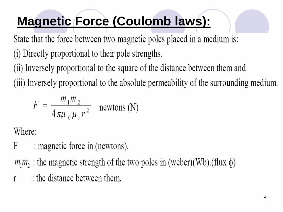
Magnetic Force (Coulomb laws):
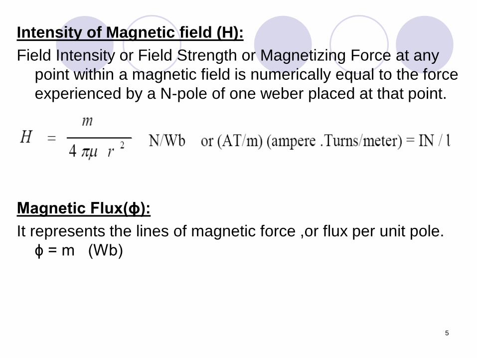
Intensity of Magnetic field (H):
Field Intensity or Field Strength or Magnetizing Force at any
point within a magnetic field is numerically equal to the force
experienced by a N-pole of one weber placed at that point.
Magnetic Flux(ɸ):
It represents the lines of magnetic force ,or flux per unit pole.
ɸ = m (Wb)
5
6
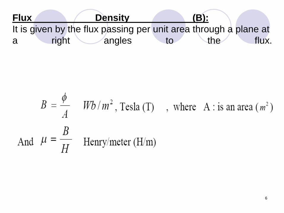
Flux Density (B):
It is given by the flux passing per unit area through a plane at
a right angles to the flux.
7
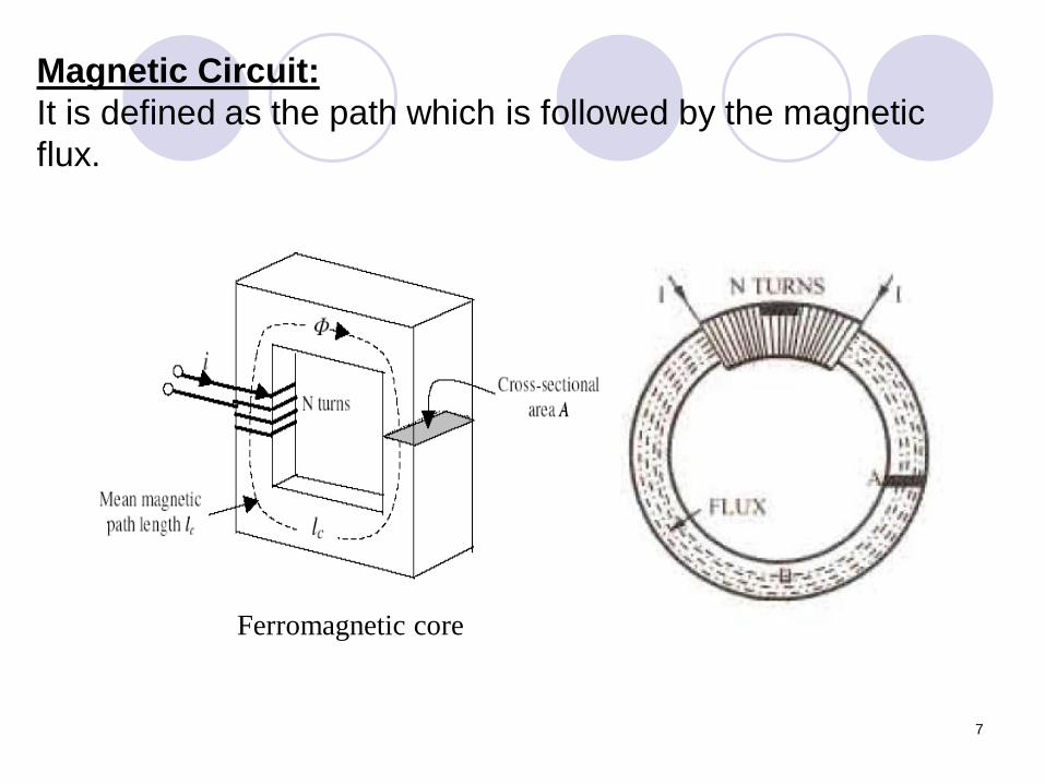
Magnetic Circuit:
It is defined as the path which is followed by the magnetic
flux.
Ferromagnetic core
8
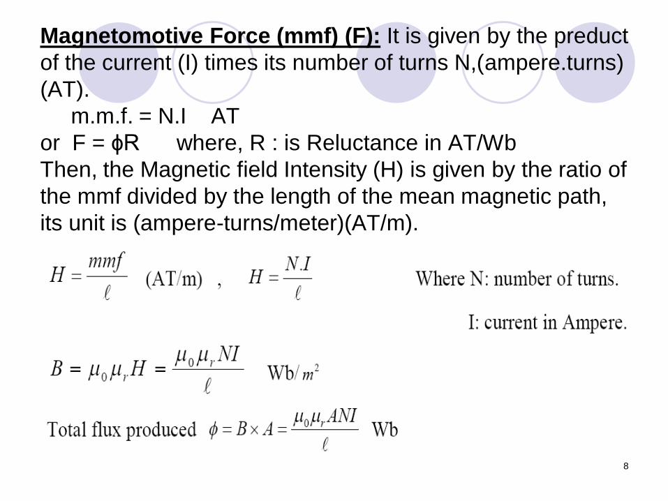
Magnetomotive Force (mmf) (F): It is given by the preduct
of the current (I) times its number of turns N,(ampere.turns)
(AT).
m.m.f. = N.I AT
or F = ɸR where, R : is Reluctance in AT/Wb
Then, the Magnetic field Intensity (H) is given by the ratio of
the mmf divided by the length of the mean magnetic path,
its unit is (ampere-turns/meter)(AT/m).
9
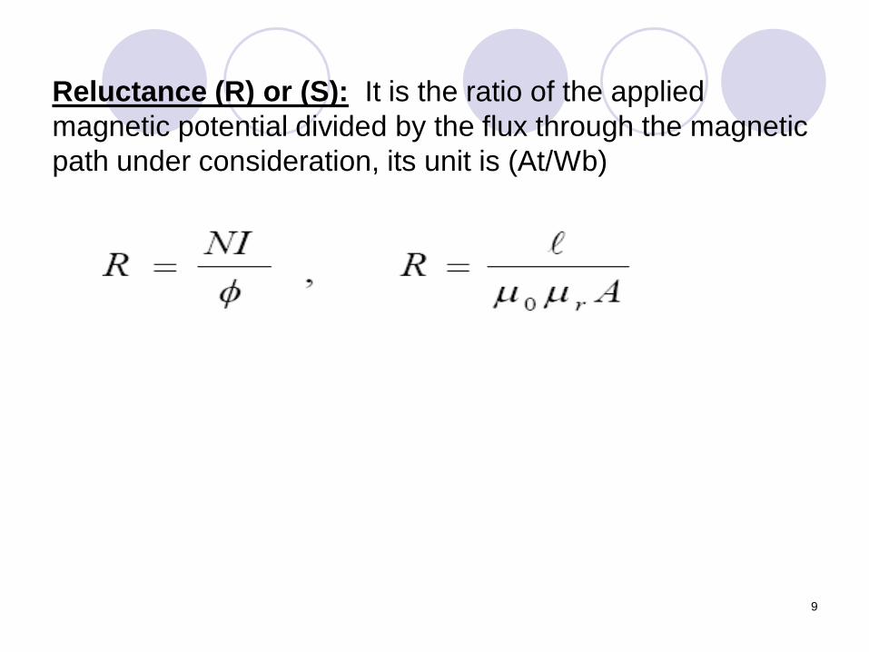
Reluctance (R) or (S): It is the ratio of the applied
magnetic potential divided by the flux through the magnetic
path under consideration, its unit is (At/Wb)
10
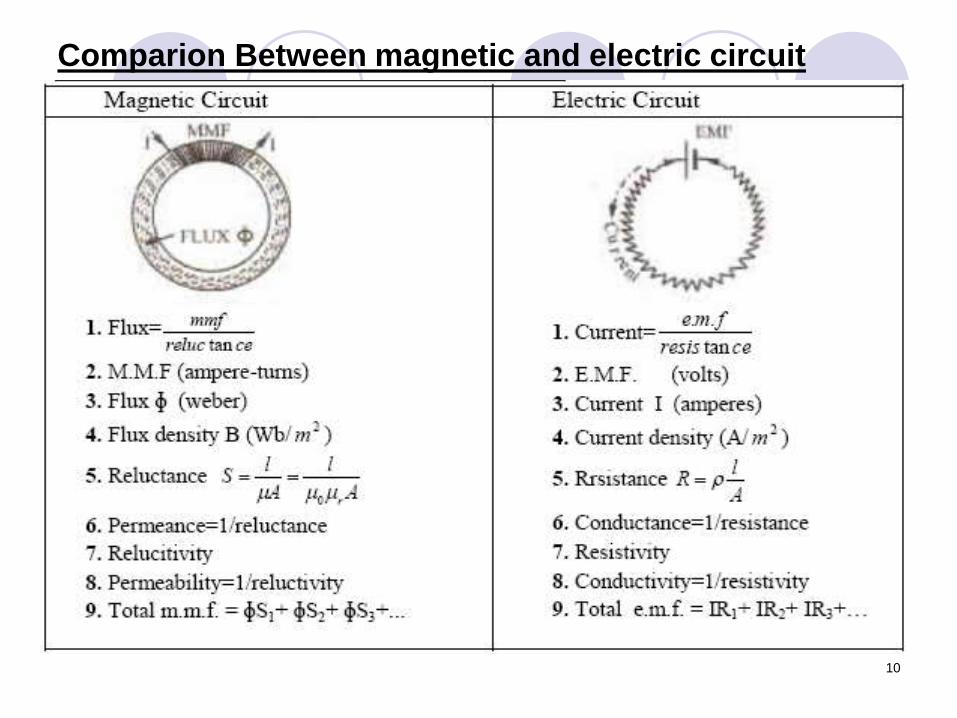
Comparion Between magnetic and electric circuit
11
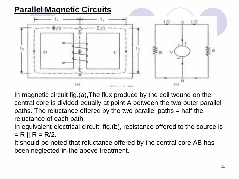
Parallel Magnetic Circuits
In magnetic circuit fig.(a),The flux produce by the coil wound on the
central core is divided equally at point A between the two outer parallel
paths. The reluctance offered by the two parallel paths = half the
reluctance of each path.
In equivalent electrical circuit, fig.(b), resistance offered to the source is
= R || R = R/2.
It should be noted that reluctance offered by the central core AB has
been neglected in the above treatment.
12
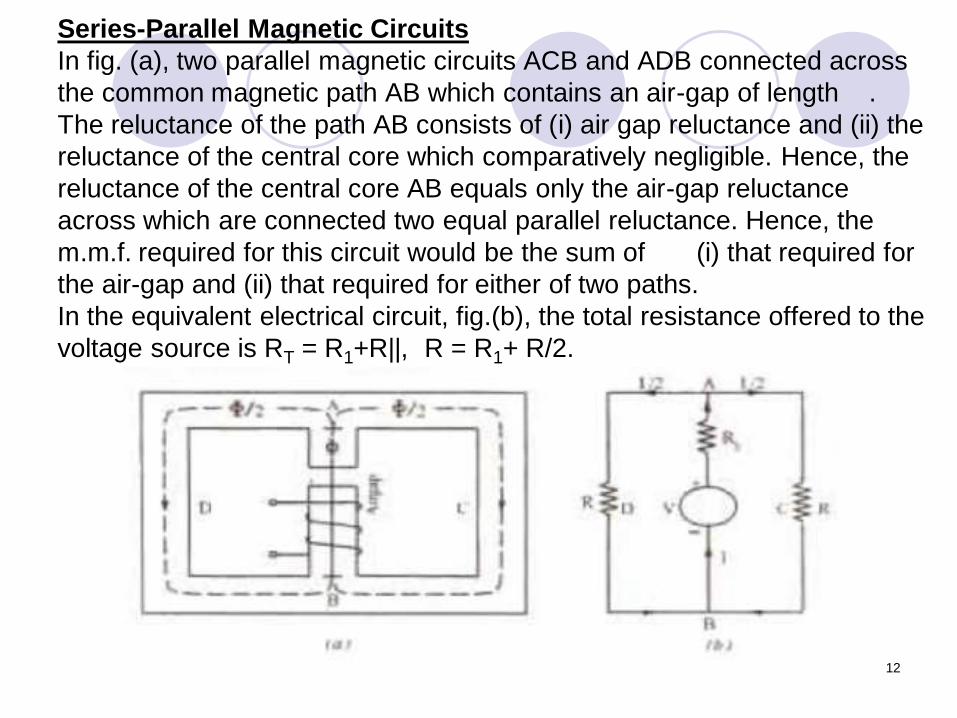
Series-Parallel Magnetic Circuits
In fig. (a), two parallel magnetic circuits ACB and ADB connected across
the common magnetic path AB which contains an air-gap of length .
The reluctance of the path AB consists of (i) air gap reluctance and (ii) the
reluctance of the central core which comparatively negligible. Hence, the
reluctance of the central core AB equals only the air-gap reluctance
across which are connected two equal parallel reluctance. Hence, the
m.m.f. required for this circuit would be the sum of (i) that required for
the air-gap and (ii) that required for either of two paths.
In the equivalent electrical circuit, fig.(b), the total resistance offered to the
voltage source is RT = R1+R||, R = R1+ R/2.
13
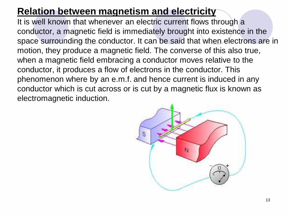
Relation between magnetism and electricityIt is well known that whenever an electric current flows through a
conductor, a magnetic field is immediately brought into existence in the
space surrounding the conductor. It can be said that when electrons are in
motion, they produce a magnetic field. The converse of this also true,
when a magnetic field embracing a conductor moves relative to the
conductor, it produces a flow of electrons in the conductor. This
phenomenon where by an e.m.f. and hence current is induced in any
conductor which is cut across or is cut by a magnetic flux is known as
electromagnetic induction.
14
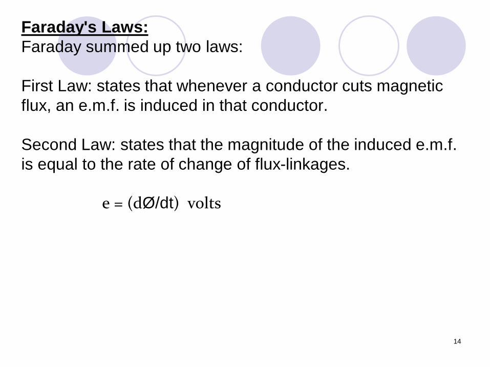
Faraday's Laws:
Faraday summed up two laws:
First Law: states that whenever a conductor cuts magnetic
flux, an e.m.f. is induced in that conductor.
Second Law: states that the magnitude of the induced e.m.f.
is equal to the rate of change of flux-linkages.
e = (dØ/dt) volts
15
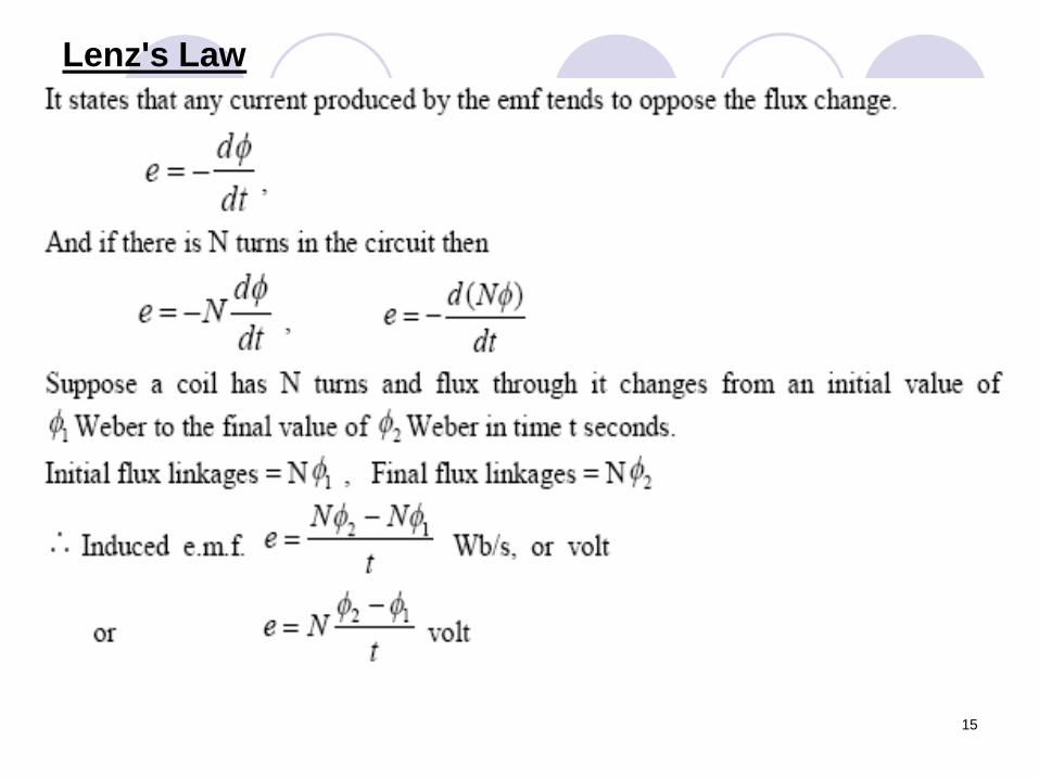
Lenz's Law
16
Induced e.m.f.:
Induced e.m.f. can be either: (i) dynamically or (ii) statically
induced. In the first case, usually the field is stationary and
conductors cut across it (as in d.c. generators). But in the
second case, usually the conductors or the coil remains
stationary and flux linked with it is changed by simply
increasing or decreasing the current producing this flux (as
in transformers).
Self-Induced e.m.f.:
This is the e.m.f. induced in a coil due to the change of its
own flux linked it. If current through the coil is changed,
then the flux linked with its own turns will also change,
which will produce in it that is called self-induced e.m.f. the
direction of this e.m.f. (as given by Lenz's law) would be
such as to oppose any change of flux which is, in fact, the
very cause of its production. Hence it is induction.
17
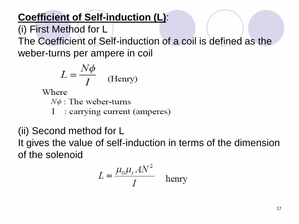
Coefficient of Self-induction (L):
(i) First Method for L
The Coefficient of Self-induction of a coil is defined as the
weber-turns per ampere in coil
(ii) Second method for L
It gives the value of self-induction in terms of the dimension
of the solenoid
18
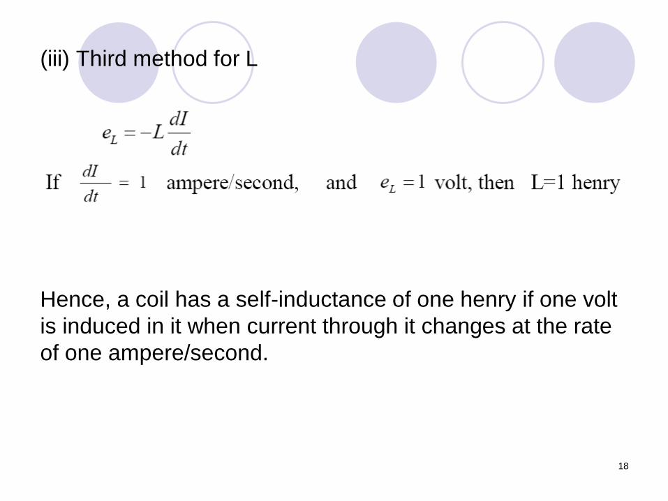
(iii) Third method for L
Hence, a coil has a self-inductance of one henry if one volt
is induced in it when current through it changes at the rate
of one ampere/second.
19
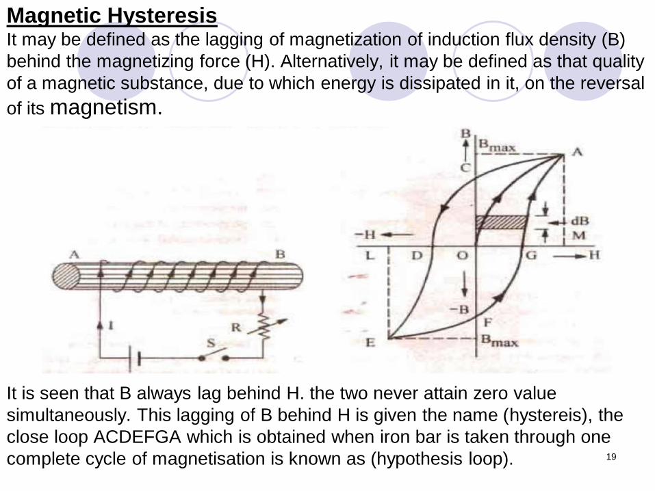
Magnetic HysteresisIt may be defined as the lagging of magnetization of induction flux density (B)
behind the magnetizing force (H). Alternatively, it may be defined as that quality
of a magnetic substance, due to which energy is dissipated in it, on the reversal
of its magnetism.
It is seen that B always lag behind H. the two never attain zero value
simultaneously. This lagging of B behind H is given the name (hystereis), the
close loop ACDEFGA which is obtained when iron bar is taken through one
complete cycle of magnetisation is known as (hypothesis loop).
20
CHAPTER TWO : D.C. MACHINES
One of energy can be obtained from the other form with the help of
converters. Converters that are used to continuously translate
electrical input to mechanical output or vice versa are called electric
machines. The process of translation is known as electromechanical
energy conversion.
An electrical machine is link between an electrical system and a
mechanical system.
Conversion from mechanical to electrical: generator
Conversion from electrical to mechanical: motor
D.C. Generator Principle
the essential components of a generator are:
(a) A magnetic field
(b) Conductor or a group of conductors
(c) Motion of conductor w.r.t. magnetic field.
21
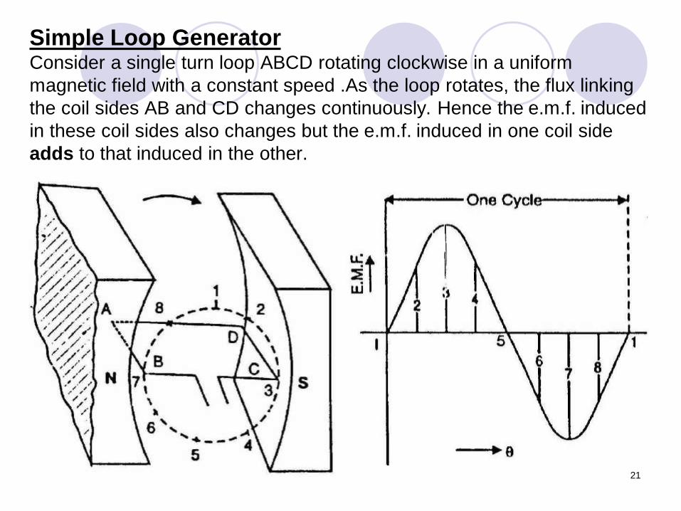
Simple Loop GeneratorConsider a single turn loop ABCD rotating clockwise in a uniform
magnetic field with a constant speed .As the loop rotates, the flux linking
the coil sides AB and CD changes continuously. Hence the e.m.f. induced
in these coil sides also changes but the e.m.f. induced in one coil side
adds to that induced in the other.
22
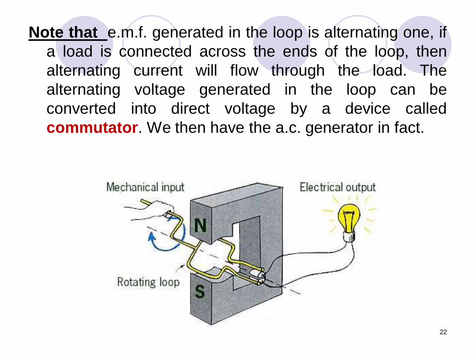
Note that e.m.f. generated in the loop is alternating one, if
a load is connected across the ends of the loop, then
alternating current will flow through the load. The
alternating voltage generated in the loop can be
converted into direct voltage by a device called
commutator. We then have the a.c. generator in fact.
23
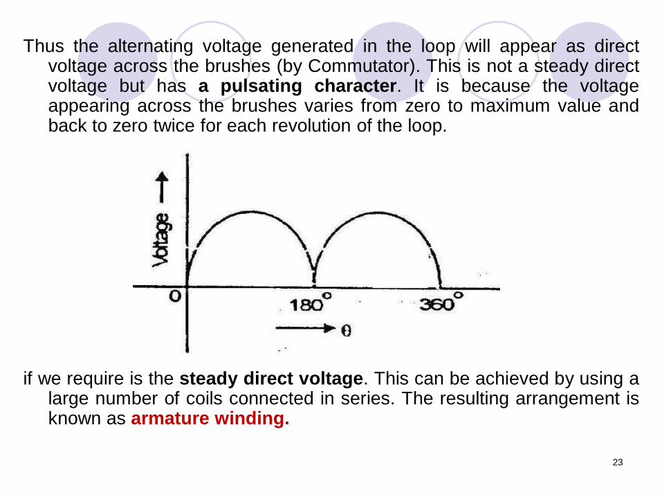
Thus the alternating voltage generated in the loop will appear as directvoltage across the brushes (by Commutator). This is not a steady directvoltage but has a pulsating character. It is because the voltageappearing across the brushes varies from zero to maximum value andback to zero twice for each revolution of the loop.
if we require is the steady direct voltage. This can be achieved by using alarge number of coils connected in series. The resulting arrangement isknown as armature winding.
24
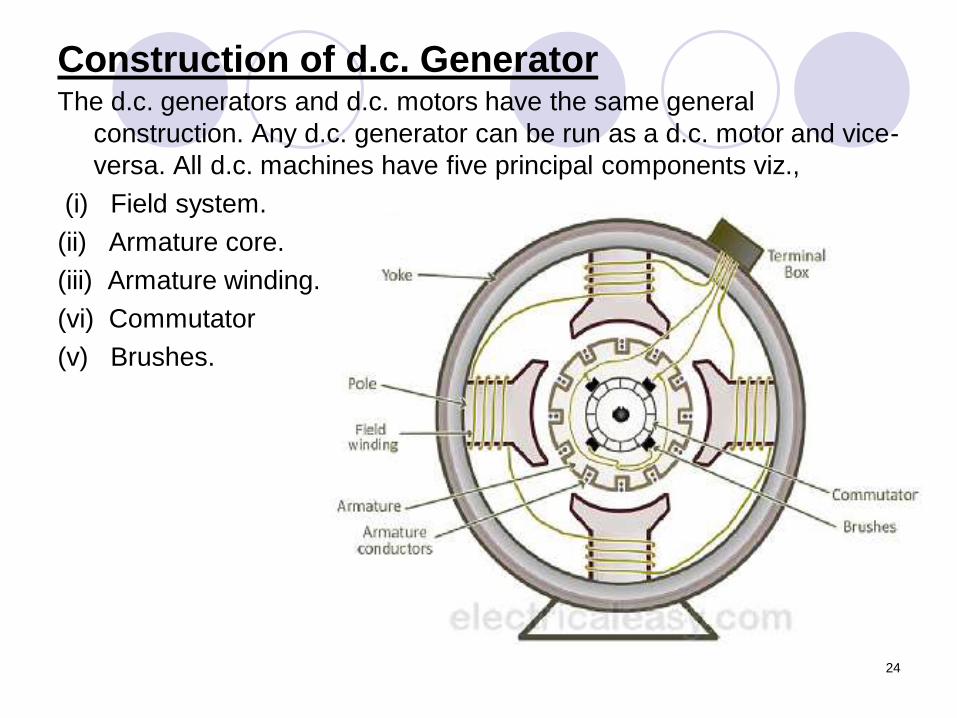
Construction of d.c. GeneratorThe d.c. generators and d.c. motors have the same general
construction. Any d.c. generator can be run as a d.c. motor and vice-
versa. All d.c. machines have five principal components viz.,
(i) Field system.
(ii) Armature core.
(iii) Armature winding.
(vi) Commutator
(v) Brushes.
25
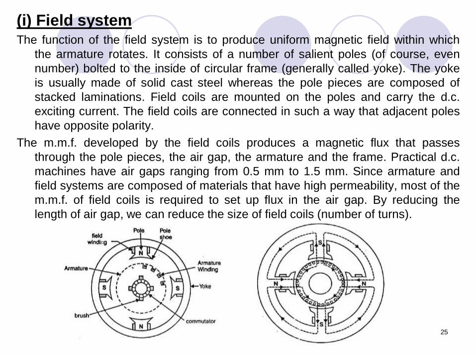
(i) Field systemThe function of the field system is to produce uniform magnetic field within which
the armature rotates. It consists of a number of salient poles (of course, even
number) bolted to the inside of circular frame (generally called yoke). The yoke
is usually made of solid cast steel whereas the pole pieces are composed of
stacked laminations. Field coils are mounted on the poles and carry the d.c.
exciting current. The field coils are connected in such a way that adjacent poles
have opposite polarity.
The m.m.f. developed by the field coils produces a magnetic flux that passes
through the pole pieces, the air gap, the armature and the frame. Practical d.c.
machines have air gaps ranging from 0.5 mm to 1.5 mm. Since armature and
field systems are composed of materials that have high permeability, most of the
m.m.f. of field coils is required to set up flux in the air gap. By reducing the
length of air gap, we can reduce the size of field coils (number of turns).
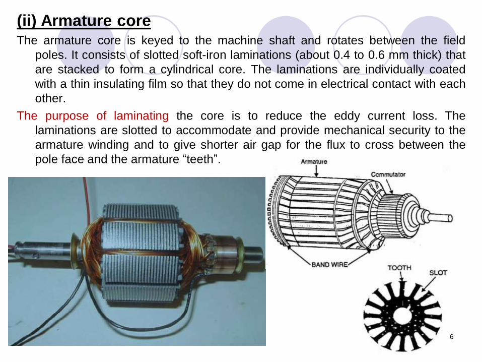
(ii) Armature coreThe armature core is keyed to the machine shaft and rotates between the field
poles. It consists of slotted soft-iron laminations (about 0.4 to 0.6 mm thick) that
are stacked to form a cylindrical core. The laminations are individually coated
with a thin insulating film so that they do not come in electrical contact with each
other.
The purpose of laminating the core is to reduce the eddy current loss. The
laminations are slotted to accommodate and provide mechanical security to the
armature winding and to give shorter air gap for the flux to cross between the
pole face and the armature “teeth”.
26
(iii) Armature windingThe slots of the armature core hold insulated conductors that are connected in a suitable
manner. This is known as armature winding. This is the winding in which “working” e.m.f. is
induced. The armature conductors are connected in series-parallel; the conductors being
connected in series so as to increase the voltage and in parallel paths so as to increase the
current. The armature winding of a d.c. machine is a closed-circuit winding; the
conductors being connected in a symmetrical manner forming a closed loop or series of
closed loops.
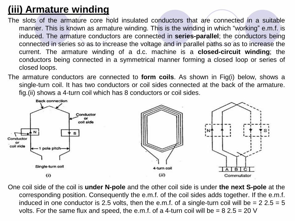
The armature conductors are connected to form coils. As shown in Fig(i) below, shows a
single-turn coil. It has two conductors or coil sides connected at the back of the armature.
fig.(ii) shows a 4-turn coil which has 8 conductors or coil sides.
One coil side of the coil is under N-pole and the other coil side is under the next S-pole at the
corresponding position. Consequently the e.m.f. of the coil sides adds together. If the e.m.f.
induced in one conductor is 2.5 volts, then the e.m.f. of a single-turn coil will be = 2 2.5 = 5
volts. For the same flux and speed, the e.m.f. of a 4-turn coil will be = 8 2.5 = 20 V
28
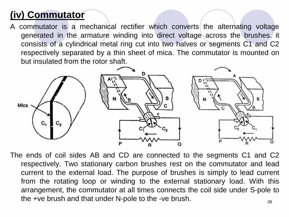
(iv) CommutatorA commutator is a mechanical rectifier which converts the alternating voltage
generated in the armature winding into direct voltage across the brushes. it
consists of a cylindrical metal ring cut into two halves or segments C1 and C2
respectively separated by a thin sheet of mica. The commutator is mounted on
but insulated from the rotor shaft.
The ends of coil sides AB and CD are connected to the segments C1 and C2
respectively. Two stationary carbon brushes rest on the commutator and lead
current to the external load. The purpose of brushes is simply to lead current
from the rotating loop or winding to the external stationary load. With this
arrangement, the commutator at all times connects the coil side under S-pole to
the +ve brush and that under N-pole to the -ve brush.
29
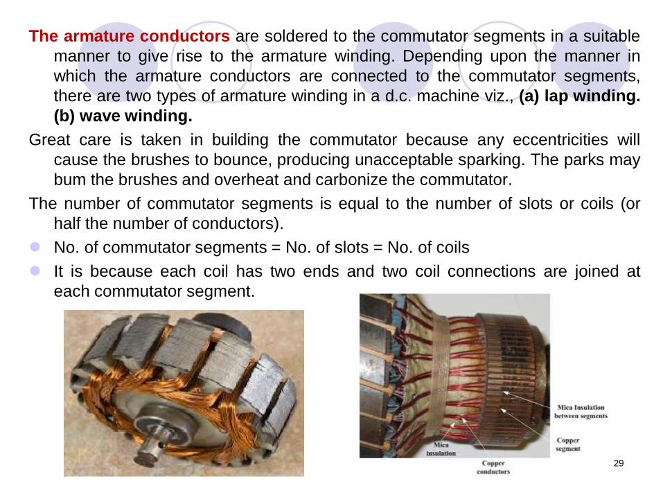
The armature conductors are soldered to the commutator segments in a suitable
manner to give rise to the armature winding. Depending upon the manner in
which the armature conductors are connected to the commutator segments,
there are two types of armature winding in a d.c. machine viz., (a) lap winding.
(b) wave winding.
Great care is taken in building the commutator because any eccentricities will
cause the brushes to bounce, producing unacceptable sparking. The parks may
bum the brushes and overheat and carbonize the commutator.
The number of commutator segments is equal to the number of slots or coils (or
half the number of conductors).
No. of commutator segments = No. of slots = No. of coils
It is because each coil has two ends and two coil connections are joined at
each commutator segment.
30
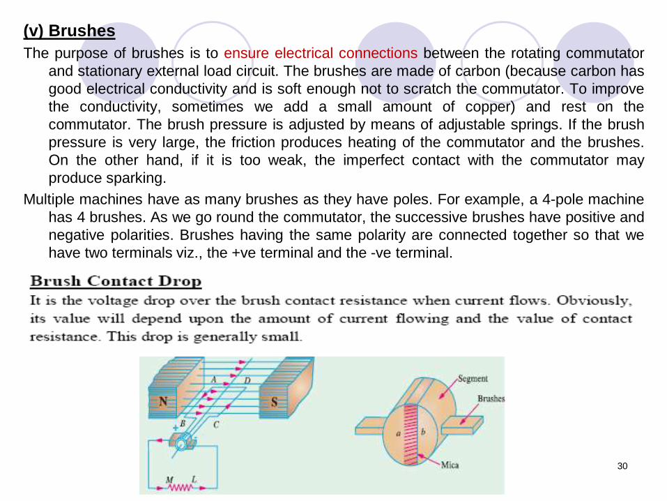
(v) Brushes
The purpose of brushes is to ensure electrical connections between the rotating commutator
and stationary external load circuit. The brushes are made of carbon (because carbon has
good electrical conductivity and is soft enough not to scratch the commutator. To improve
the conductivity, sometimes we add a small amount of copper) and rest on the
commutator. The brush pressure is adjusted by means of adjustable springs. If the brush
pressure is very large, the friction produces heating of the commutator and the brushes.
On the other hand, if it is too weak, the imperfect contact with the commutator may
produce sparking.
Multiple machines have as many brushes as they have poles. For example, a 4-pole machine
has 4 brushes. As we go round the commutator, the successive brushes have positive and
negative polarities. Brushes having the same polarity are connected together so that we
have two terminals viz., the +ve terminal and the -ve terminal.
31
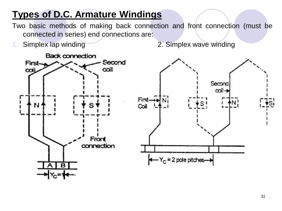
Types of D.C. Armature WindingsTwo basic methods of making back connection and front connection (must be
connected in series) end connections are:
1. Simplex lap winding 2. Simplex wave winding
32
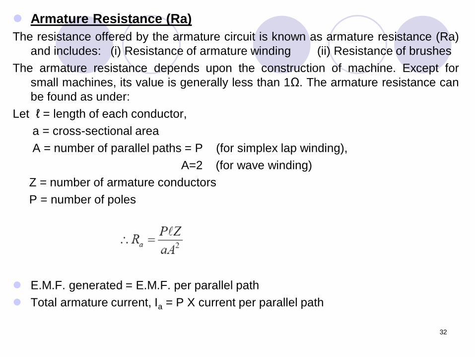
Armature Resistance (Ra)
The resistance offered by the armature circuit is known as armature resistance (Ra)
and includes: (i) Resistance of armature winding (ii) Resistance of brushes
The armature resistance depends upon the construction of machine. Except for
small machines, its value is generally less than 1Ω. The armature resistance can
be found as under:
Let ℓ = length of each conductor,
a = cross-sectional area
A = number of parallel paths = P (for simplex lap winding),
A=2 (for wave winding)
Z = number of armature conductors
P = number of poles
E.M.F. generated = E.M.F. per parallel path
Total armature current, Ia = P X current per parallel path
33
Applications of Lap and Wave Windings
In multiple machines, for a given number of poles (P) and armature
conductors (Z), a wave winding has a higher terminal voltage than a
lap winding because it has more conductors in series. On the other
hand, the lap winding carries more current than a wave winding
because it has more parallel paths.
In small machines, the current-carrying capacity of the armature
conductors is not critical and in order to achieve suitable voltages,
wave windings are used.
On the other hand, in large machines suitable voltages are easily
obtained because of the availability of large number of armature
conductors and the current carrying capacity is more critical. Hence in
large machines, lap windings are used.
Note: In general, a high-current armature is lap-wound to provide a large
number of parallel paths and a low-current armature is wave-wound to
provide a small number of parallel paths.
34
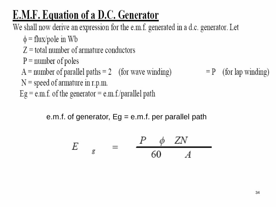
e.m.f. of generator, Eg = e.m.f. per parallel path
35
Types of D.C. Generators
Generators are generally classified according to their
methods of field excitation. On this basis, d.c. generators
are divided into the following two classes:
(i) Separately excited d.c. generators
(ii) Self-excited d.c. generators
The behaviour of a d.c. generator on load depends upon the
method of field excitation adopted.
36
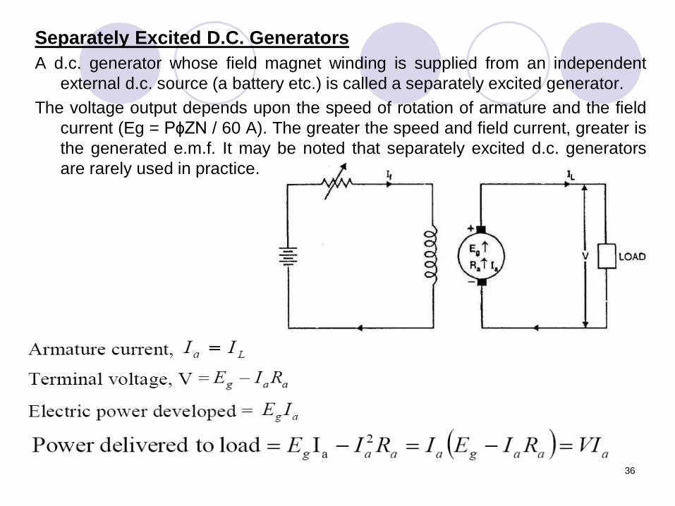
Separately Excited D.C. Generators
A d.c. generator whose field magnet winding is supplied from an independent
external d.c. source (a battery etc.) is called a separately excited generator.
The voltage output depends upon the speed of rotation of armature and the field
current (Eg = PɸZN / 60 A). The greater the speed and field current, greater is
the generated e.m.f. It may be noted that separately excited d.c. generators
are rarely used in practice.
Self-Excited D.C. Generators
A d.c. generators are normally of self-excited type,
whose field magnet winding is supplied current
from the output of the generator itself. There are
three types of self-excited generators depending
upon the manner in which the field winding is
connected to the armature, namely;
(i) Series generator,
(ii) Shunt generator, and
(iii) Compound generator
37
38
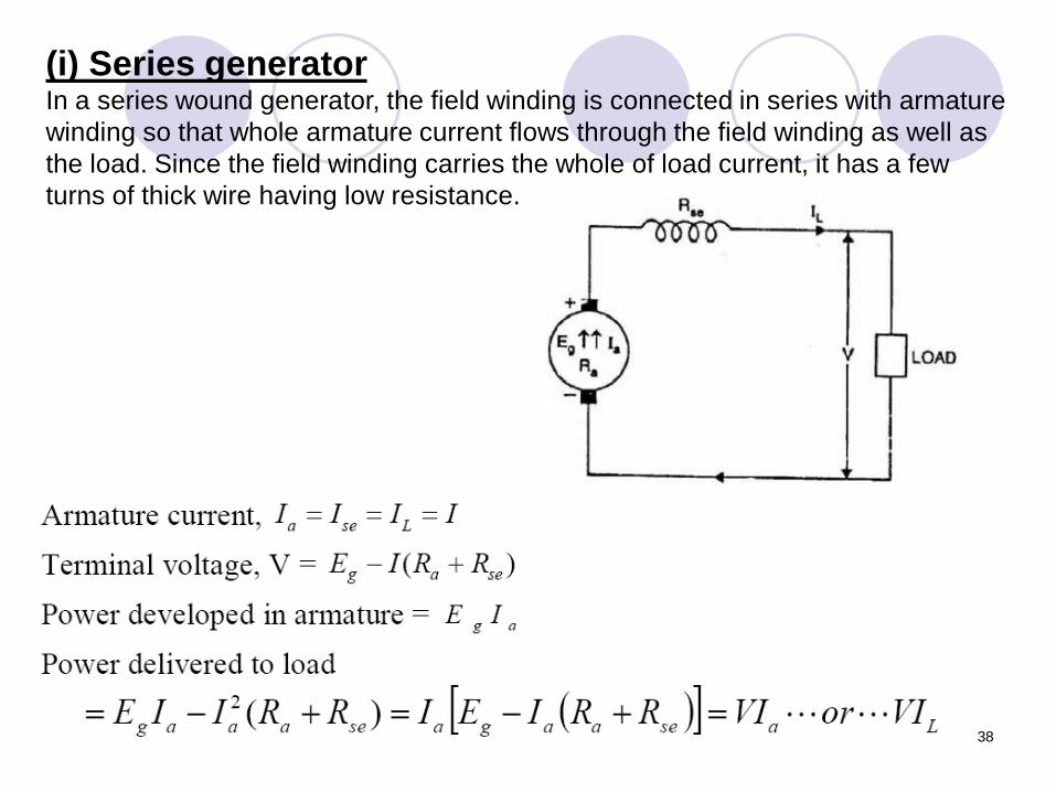
(i) Series generatorIn a series wound generator, the field winding is connected in series with armature
winding so that whole armature current flows through the field winding as well as
the load. Since the field winding carries the whole of load current, it has a few
turns of thick wire having low resistance.
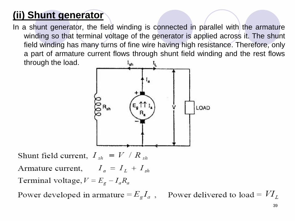
(ii) Shunt generatorIn a shunt generator, the field winding is connected in parallel with the armature
winding so that terminal voltage of the generator is applied across it. The shunt
field winding has many turns of fine wire having high resistance. Therefore, only
a part of armature current flows through shunt field winding and the rest flows
through the load.
39
40
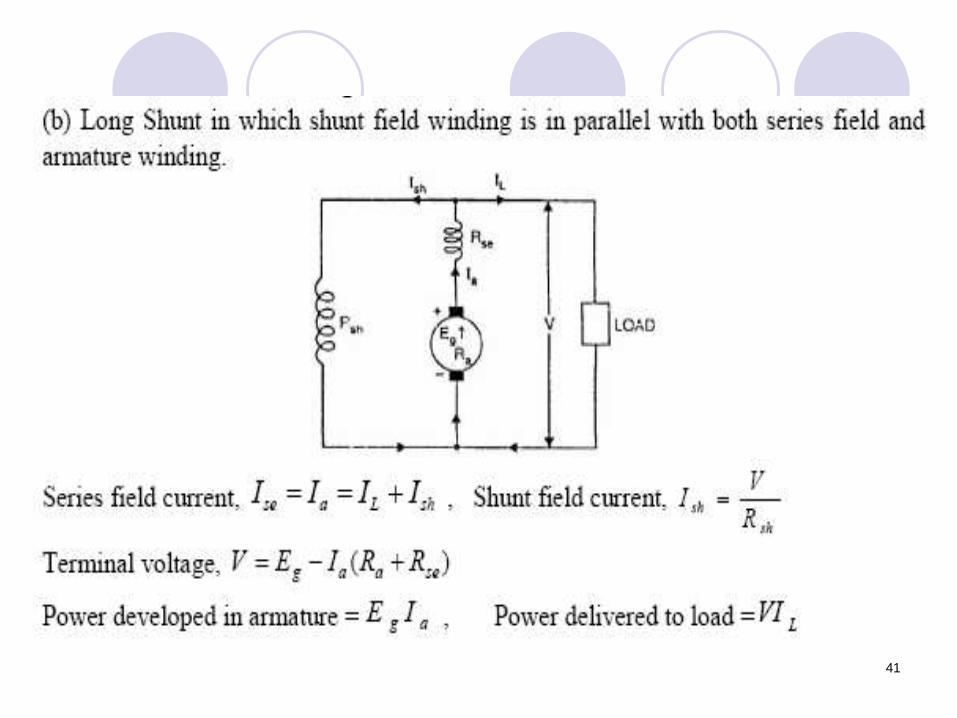
41
1
2
3
4
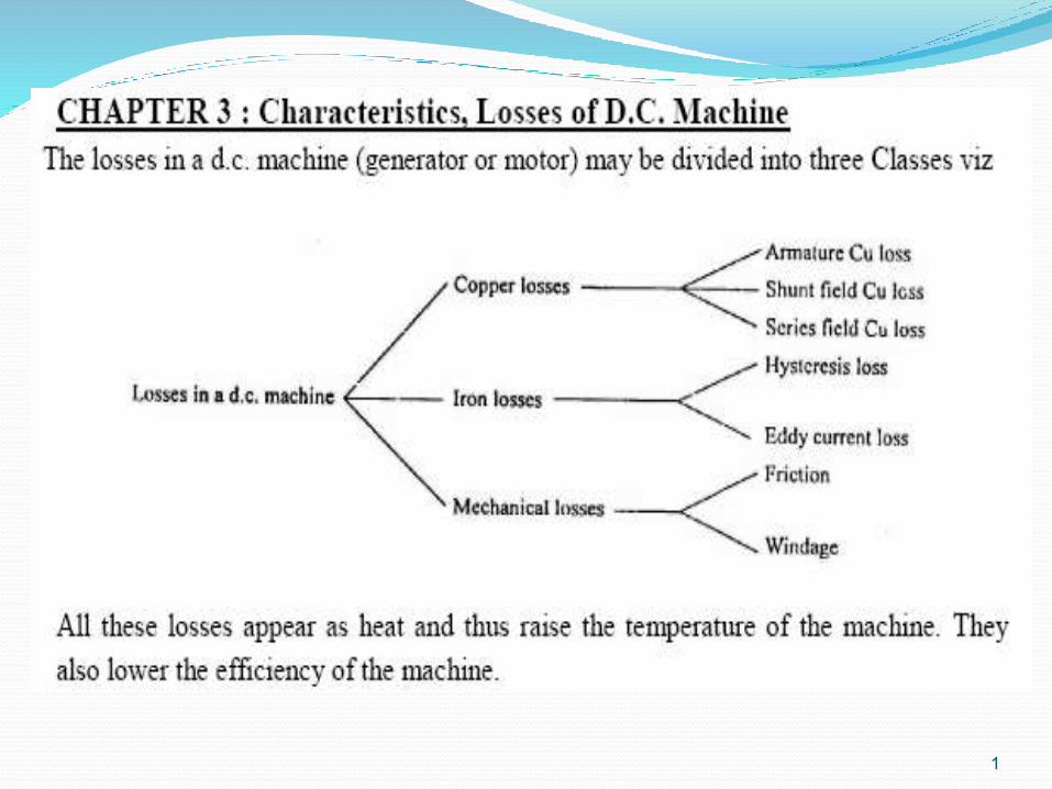
3. Mechanical lossesThese losses are due to friction and windage.
(i) Friction loss e, bearing friction, brush friction etc.
(ii) windage loss , air friction of rotating armature.
These losses depend upon the speed of the machine. But for a given speed, they
are practically constant.
Note. Iron losses and mechanical losses together are called stray or rotational
losses.
5
6
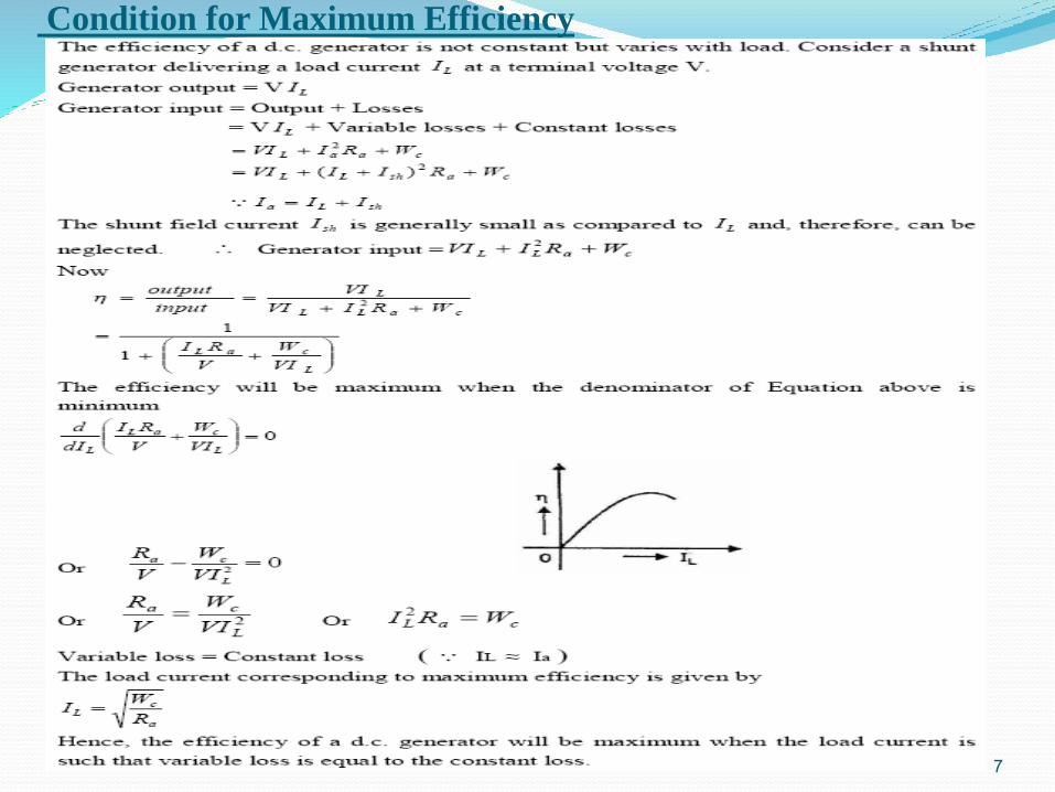
Condition for Maximum Efficiency
7
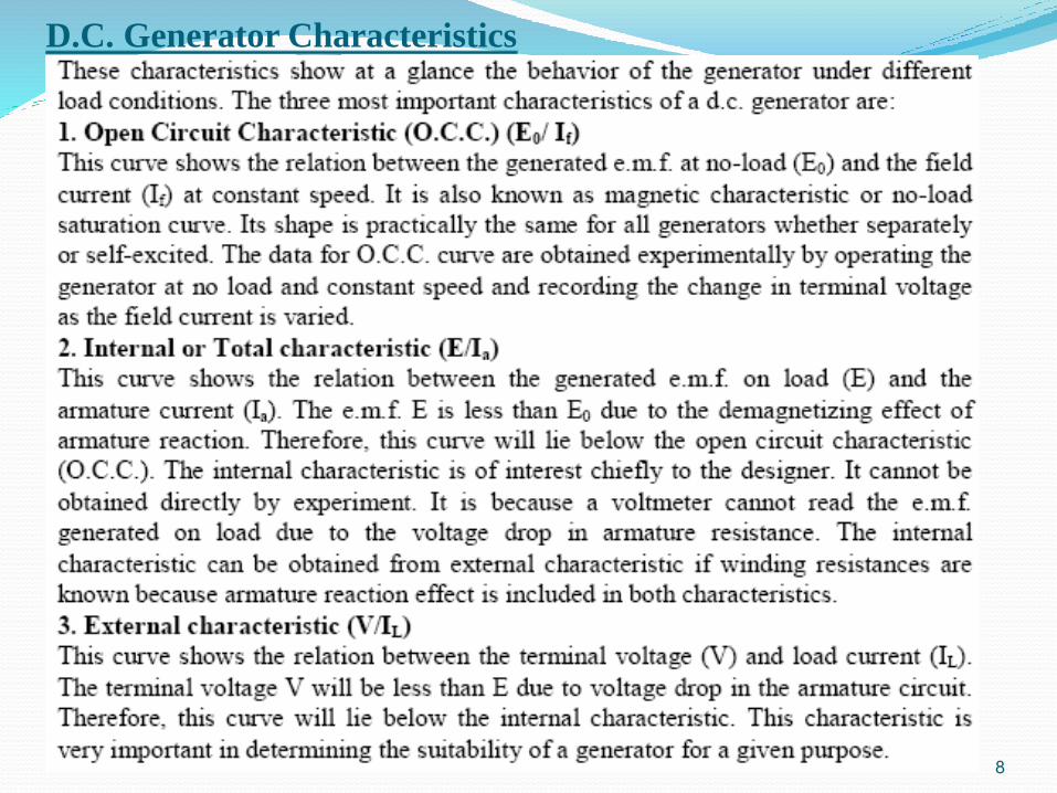
D.C. Generator Characteristics
8
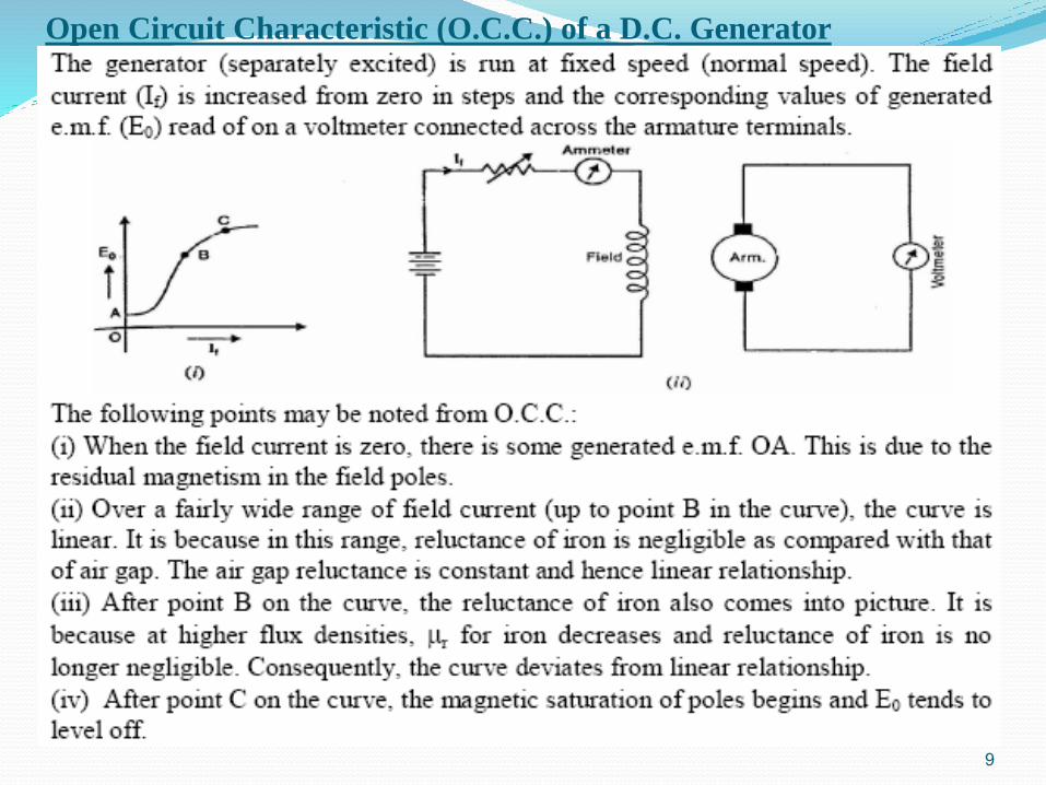
Open Circuit Characteristic (O.C.C.) of a D.C. Generator
9
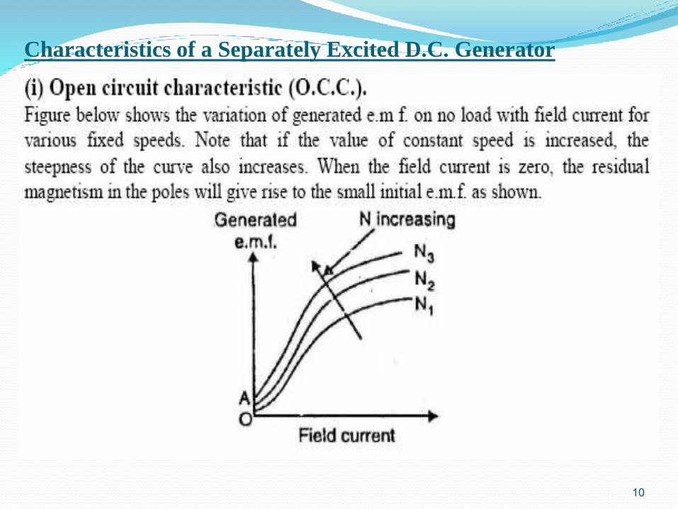
Characteristics of a Separately Excited D.C. Generator
10
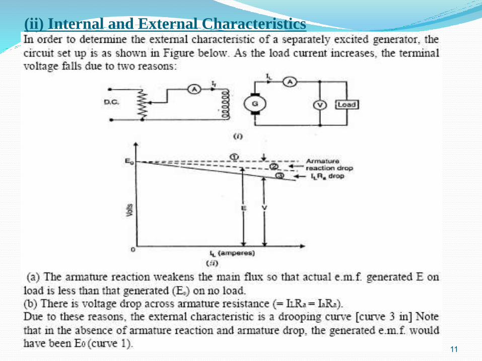
(ii) Internal and External Characteristics
11
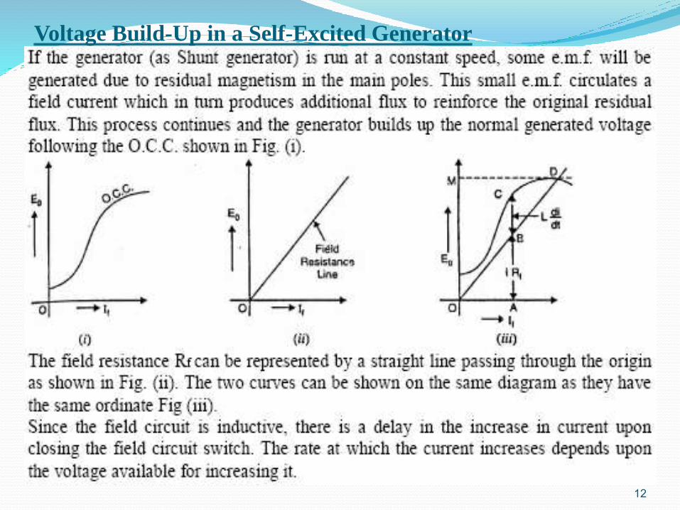
Voltage Build-Up in a Self-Excited Generator
12
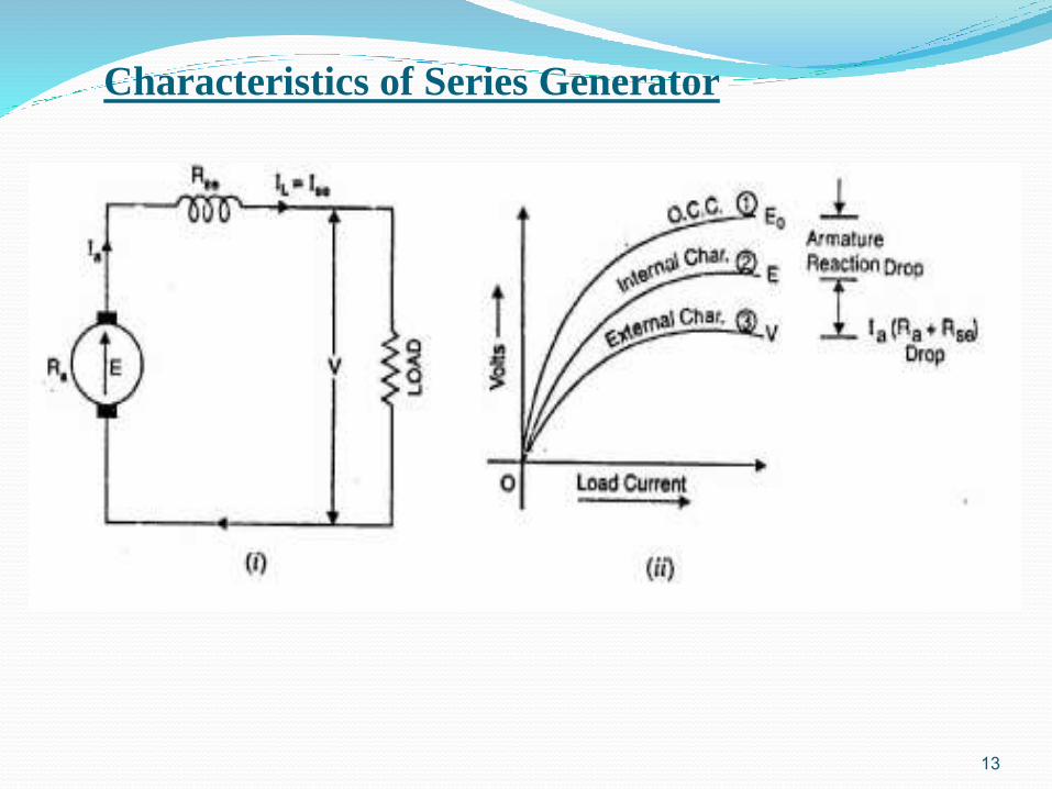
Characteristics of Series Generator
13
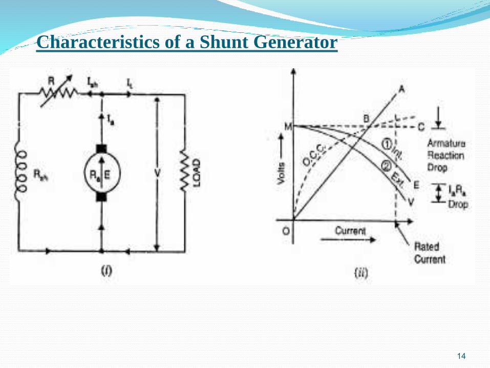
Characteristics of a Shunt Generator
14
Voltage Regulation
15
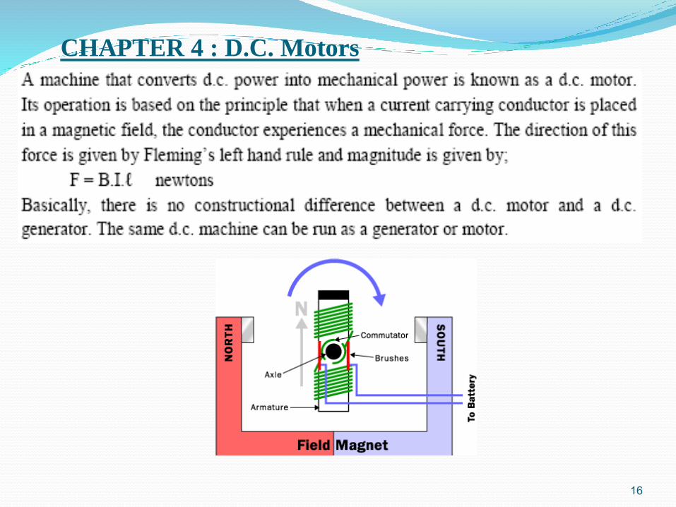
CHAPTER 4 : D.C. Motors
16
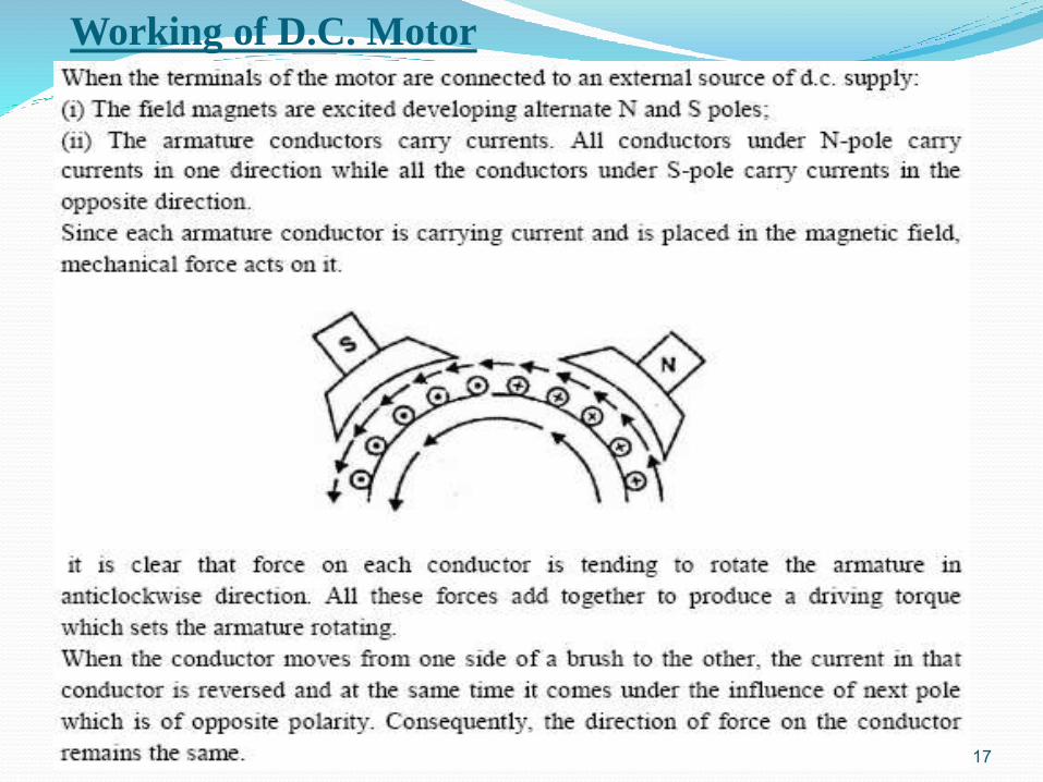
Working of D.C. Motor
17
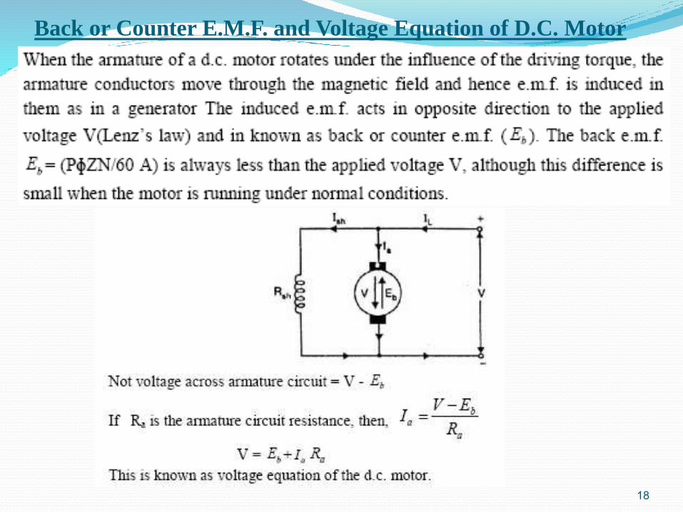
Back or Counter E.M.F. and Voltage Equation of D.C. Motor
18
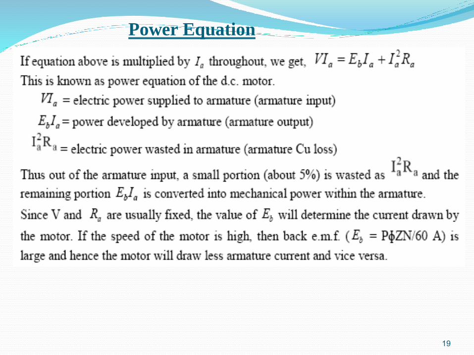
Power Equation
19
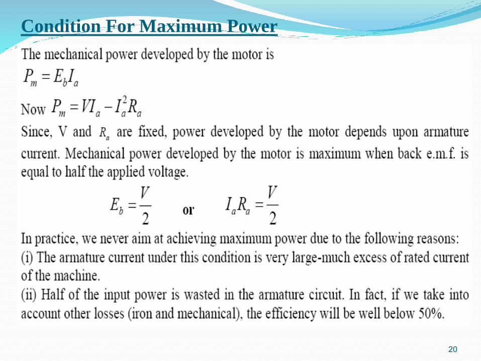
Condition For Maximum Power
20
Significance of Back E.M.F.
21
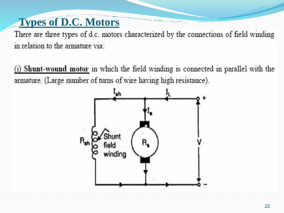
Types of D.C. Motors
22
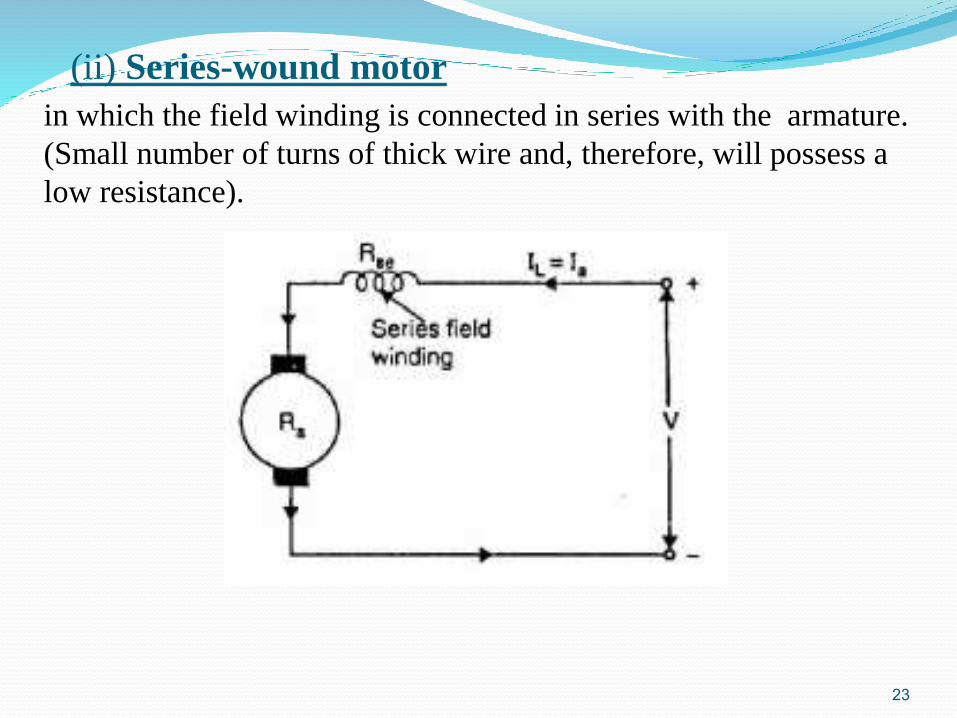
(ii) Series-wound motor
23
in which the field winding is connected in series with the armature.
(Small number of turns of thick wire and, therefore, will possess a
low resistance).
(iii) Compound-wound motor
24
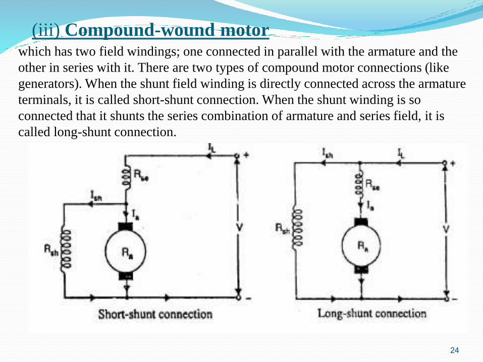
which has two field windings; one connected in parallel with the armature and the
other in series with it. There are two types of compound motor connections (like
generators). When the shunt field winding is directly connected across the armature
terminals, it is called short-shunt connection. When the shunt winding is so
connected that it shunts the series combination of armature and series field, it is
called long-shunt connection.
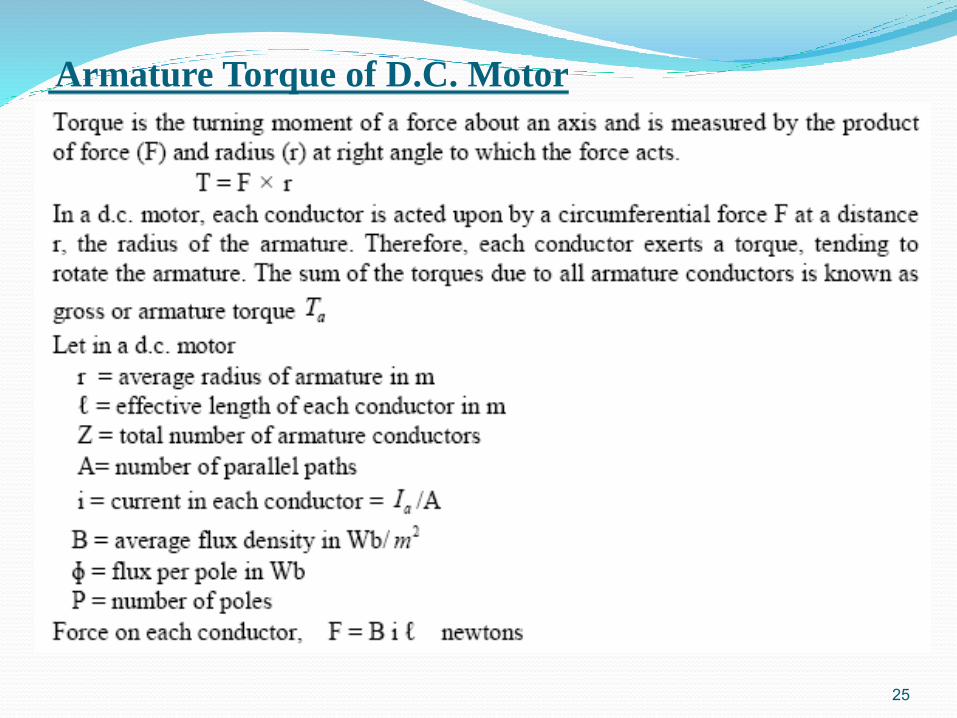
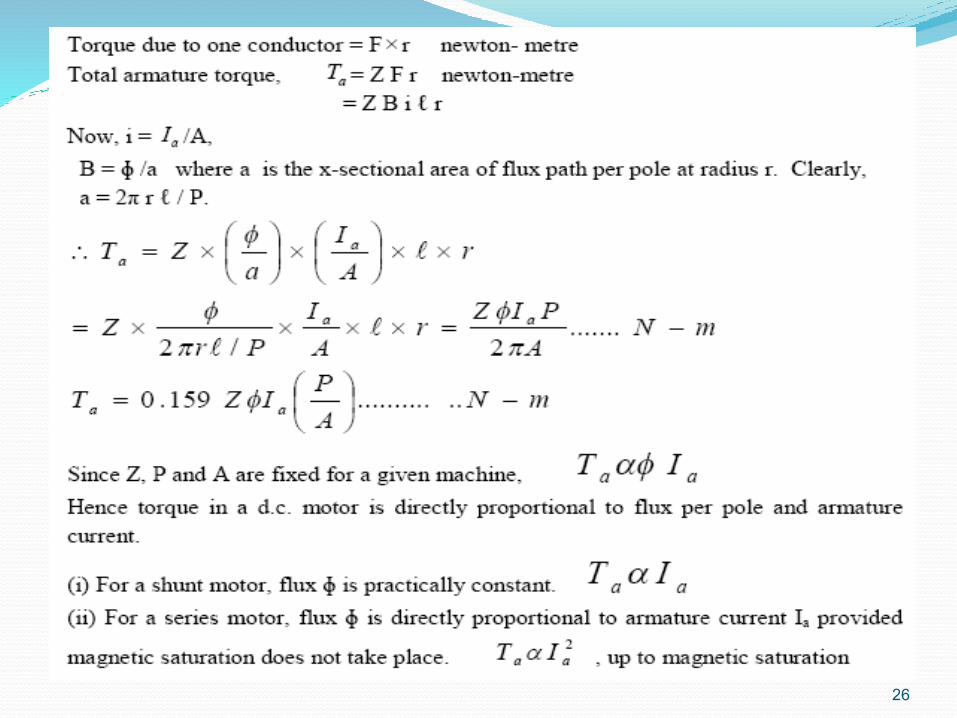
Armature Torque of D.C. Motor
25
26
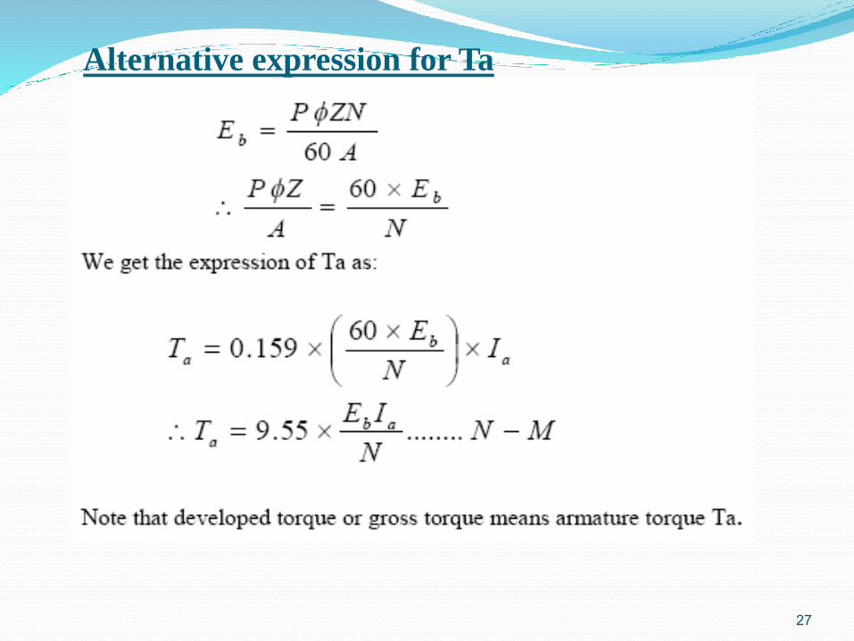
Alternative expression for Ta
27
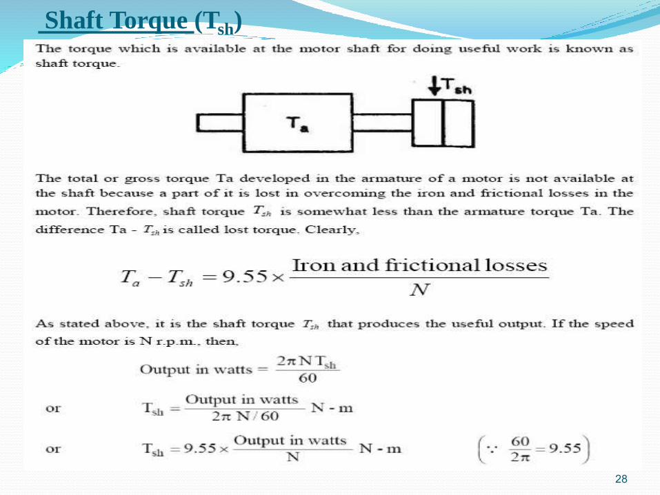
Shaft Torque (Tsh)
28
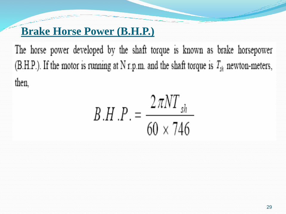
Brake Horse Power (B.H.P.)
29

30


![V.K. [Mel] Melhado III - Amazon S3...Size (Interior): 2211 MLS#: 216005258 Posted: Preview Naples Properties, LLC V.K. [Mel] Melhado III Contact Agent Property For Sale Nestled in](https://img.pdfslide.us/doc/110x75/5f04d7d77e708231d40ffc51/vk-mel-melhado-iii-amazon-s3-size-interior-2211-mls-216005258-posted.jpg)


![[v.K. Raina] Concrete Bridge Practice Analysis, D(BookZZ.org)](https://img.pdfslide.us/doc/110x75/55cf94bf550346f57ba41c76/vk-raina-concrete-bridge-practice-analysis-dbookzzorg.jpg)