Embed Size (px)
Citation preview
PHYSICS NOTES
W.R.David
DC Circuits
Syllabus:-Content20.1 Practical circuits20.2 Conservation of charge and energy20.3 Balanced potentialsLearning OutcomesCandidates should be able to:(a) recall and use appropriate circuit symbols as set out in the ASE publication Signs, Symbols andSystematics.(b) draw and interpret circuit diagrams containing sources, switches, resistors, ammeters, voltmeters,and/or any other type of component referred to in the syllabus.(c) recall Kirchhoff’s first law and appreciate the link to conservation of charge.(d) recall Kirchhoff’s second law and appreciate the link to conservation of energy.(e) derive, using Kirchhoff’s laws, a formula for the combined resistance of two or more resistors inseries.(f) solve problems using the formula for the combined resistance of two or more resistors in series.(g) derive, using Kirchhoff’s laws, a formula for the combined resistance of two or more resistors inparallel.(h) solve problems using the formula for the combined resistance of two or more resistors in parallel.(i) apply Kirchhoff’s laws to solve simple circuit problems.(j) show an understanding of the use of a potential divider circuit as a source of variable p.d.* (k) explain the use of thermistors and light-dependent resistors in potential dividers to providea potential difference which is dependent on temperature and illumination respectively.(l) recall and solve problems using the principle of the potentiometer as a means of comparing po-tential differences.
1

Circuit symbols:Electrical circuits use a lot of components and when circuits are drawn theirsymbols are used the following are the standered symbols used in circuits:-
Figure 1: Symbols of common circuit elements
Conservation of charge:The net charge of an isolated system remains constant.Charge can becreated and destroyed, but only in positive-negative pairs.
• It is not possible to destroy or create charge.
• You can cancel out the effect of a charge(or neutralize the charge on the body) on a body byadding an equal and opposite charge to it, but you can’t destroy the charge itself.
The following example makes this clearIf a glass rod is rubbed with a silk cloth, due to friction the glass gets charged positively and the silknegatively.The charging is basically due to the transfer of negative charge(electrons) from the glassto the silk.This experiment suggests that:-
• Charge is transfered but not created or destroyed.
• The total charge on the Glass silk cloth system remains the same i.e zero before rubbing andafter rubbing.
Kirchoff’s First Law:At any junction in a circuit, the sum of the currents arriving at the junctionis equal to the the sum of the currents leaving the junction.Conservation of Charge and the Kirchoff’s First Law: Kirchhoffs first rule is a statement ofconservation of electric charge. All charges that enter a given point in a circuit must leave that pointbecause charge cannot build up(accumulate) at a point. If this does not happen then charges aregetting accumulated at a point or charges are created from nowhere! both of which don’t happen Inother words - charge is conserved.
2
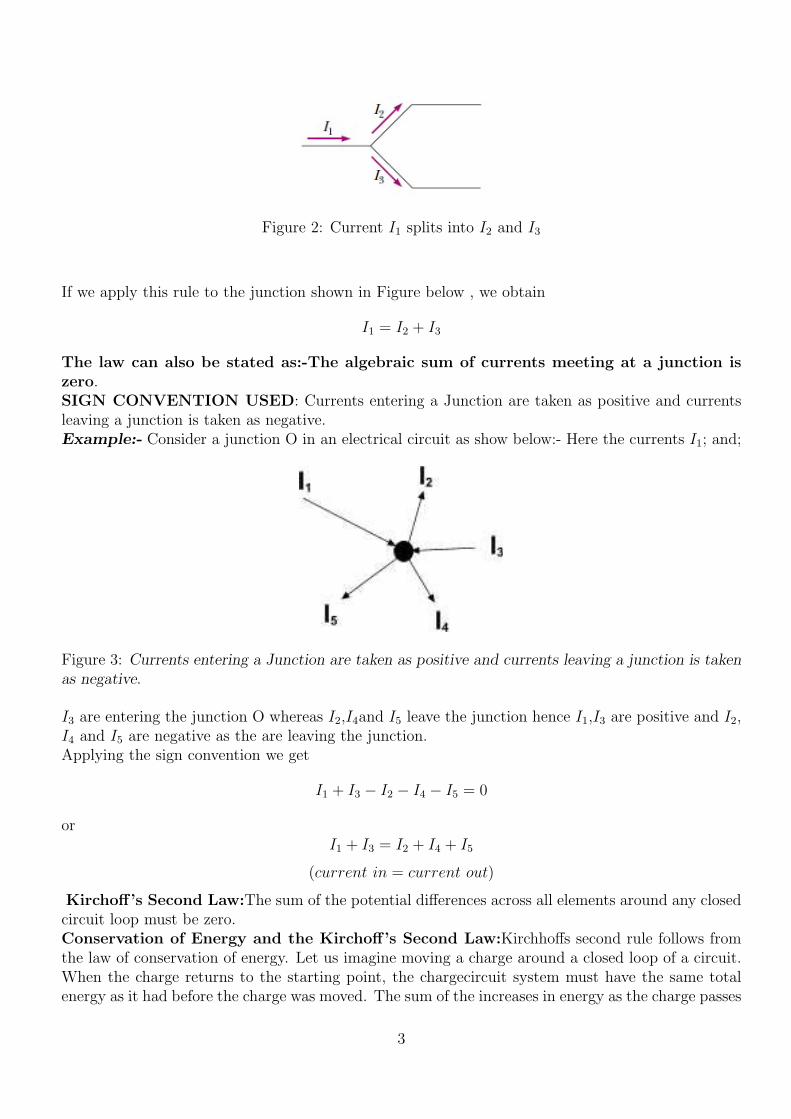
Figure 2: Current I1 splits into I2 and I3
If we apply this rule to the junction shown in Figure below , we obtain
I1 = I2 + I3
The law can also be stated as:-The algebraic sum of currents meeting at a junction iszero.SIGN CONVENTION USED: Currents entering a Junction are taken as positive and currentsleaving a junction is taken as negative.Example:- Consider a junction O in an electrical circuit as show below:- Here the currents I1; and;
Figure 3: Currents entering a Junction are taken as positive and currents leaving a junction is takenas negative.
I3 are entering the junction O whereas I2,I4and I5 leave the junction hence I1,I3 are positive and I2,I4 and I5 are negative as the are leaving the junction.Applying the sign convention we get
I1 + I3 − I2 − I4 − I5 = 0
orI1 + I3 = I2 + I4 + I5
(current in = current out)
Kirchoff’s Second Law:The sum of the potential differences across all elements around any closedcircuit loop must be zero.Conservation of Energy and the Kirchoff’s Second Law:Kirchhoffs second rule follows fromthe law of conservation of energy. Let us imagine moving a charge around a closed loop of a circuit.When the charge returns to the starting point, the chargecircuit system must have the same totalenergy as it had before the charge was moved. The sum of the increases in energy as the charge passes
3

through some circuit elements must equal the sum of the decreases in energy as it passes throughother elements. The potential energy decreases whenever the charge moves through a potential drop−IR across a resistor or whenever it moves in the reverse direction through a source of emf. Thepotential energy increases whenever the charge passes through a battery from the negative terminalto the positive terminal.Rules for applying Kirchoff’s Laws for solving problems
• Currents are labeled with the assumed sense of direction.
• The solution is carried out with the assumed sense of direction and if the actual direction of aparticular current is opposite to the assumed direction the value of current will emerge with anegative sign.
• Choose any closed loop in the given network and designate a direction (clockwise or anticlock-wise) to traverse the loop for applying the Kirchhoff’s II law.
• Go around the loop in the designated direction algebraically adding the potential differencesacross the resistors (IR Terms) and the source (cells) emf’s.
• SIGNS: If a resistor is traversed positive first (the end at which the current enters a resistoris positive) then the IR term is taken as negative, similarly for an emf source (say battery) ifthe positive is encountered first then the emf is taken as negative.
• in order to solve a particular circuit problem, the number of independent equations you needto obtain from the two rules equals the number of unknown currents.
Example ProblemFind the currents I1, I2, and I3 in the circuit shown in Figure 4 below .
Figure 4: Example Problem
• Arbitrarily choose the directions of the currents as labeled in Figure 4
• Applying Kirchhoffs junction rule to junction c gives
I1 + I2 = I3 (1)
4

• We now have one equation with three unknownsI1, I2, and I3.
• There are three loops in the circuit abcda, befcb, and aefda.
• Applying Kirchhoffs loop rule to loops abcda and befcb and traversing these loops clockwise(shown by curved arrows), we obtain the expressions for the closed loop abcda
10.0V − (6.0Ω)I1 − (2.0Ω)I3 = 0 (2)
for the closed loop befcb
−14.0V + (6.0Ω)I1 − 10.0V − (4.0Ω)I2 = 0 (3)
which gives(6.0Ω)I1 − (4.0Ω)I2 = 24.0V (4)
• Substituting into Equation I1 + I2 = I3 in the equation (2) we get
10.0V − (6.0Ω)I1 − (2.0Ω)(I1 + I2) = 0
which gives10.0V = (8.0Ω)I1 + (2.0Ω)I2 (5)
• solving equations (3) and (4) we getI1 = 2.0A
I2 = −3.0A
I3 = −1.0A
• To finalize the problem, note that I2 and I3 are both negative. This indicates only that thecurrents are opposite the direction we chose for them. However, the numerical values arecorrect.
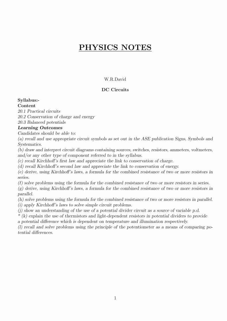
COMBINATION OF RESISTORS- RESISTANCE IN SERIES AND PARALLELRESISTORS CONNECTED IN SERIES:-The figure below shows 3 resistors connected in seriesto an Ideal battery (no internal resistance) Connection in series means the resistors are wired oneafter the other and the potential difference V is applied across the ends of the whole series.
Figure 5: Resistors in series-Note the current through all the resistors is the same but voltage is not
When a potential difference V is applied across the series the current through all the resistors isthe same, but the potential difference across each resistor is different and the sum of these individual
5
potential differences is equal to the applied potential difference V
V1 = IR1 (6)
V2 = IR2
V1 = IR3
V = V1 + V2 + V3
V = IR1 + IR2 + IR3
V = I(R1 +R2 +R3)
V
I= Req = R1 +R2 +R3
Hence the equivalent resistance of a series combination is given by
Req = R1 +R2 +R3 (7)
In general if there are n resistors connected in series then
Req = R1 +R2 +R3....Rn
IN SERIES
• The resistors connected in series can be replaced by an equivalent resistor Req
• Req has the same current I as the individual resistors
• Two resistors are said to be connected series if current can flow from one resistor to anotherwithout branching
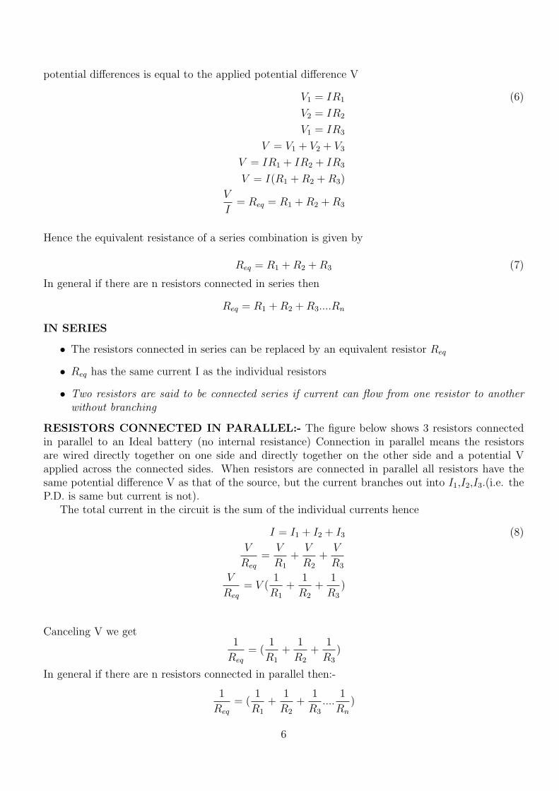
RESISTORS CONNECTED IN PARALLEL:- The figure below shows 3 resistors connectedin parallel to an Ideal battery (no internal resistance) Connection in parallel means the resistorsare wired directly together on one side and directly together on the other side and a potential Vapplied across the connected sides. When resistors are connected in parallel all resistors have thesame potential difference V as that of the source, but the current branches out into I1,I2,I3.(i.e. theP.D. is same but current is not).
The total current in the circuit is the sum of the individual currents hence
I = I1 + I2 + I3 (8)
V
Req
=V
R1
+V
R2
+V
R3
V
Req
= V (1
R1
+1
R2
+1
R3
)
Canceling V we get1
Req
= (1
R1
+1
R2
+1
R3
)
In general if there are n resistors connected in parallel then:-
1
Req
= (1
R1
+1
R2
+1
R3
....1
Rn
)
6

Figure 6: Resistance in Parellel-Note that the current branches out but voltage is the same for all 3resistors
IN PARALLEL:-
• The resistors connected in Parallel can be replaced by an equivalent resistor Req
• Req has the same current V as the individual resistors
• For resistors connected Parallel current in each of them is different but the voltage is the same
Potential Divider:The potential divider circuit (fig.7) is one of the most useful circuits.The potential divider arrange-ment can be used to divide the input voltage(Vs) in the ratio that we want. The circuit diagram fora potential divider arrangement is shown below:-For a potential divider the current through each resistor is the same (why?they are in series,hence).The
Figure 7: A potential Divider circuit
7

current in the circuit can be found by using the Ohms law and remembering that the total resistancein the circuit is R1 +R2 we get
I =Vs
R1 +R2
(9)
the voltage across the resistor R1 is given by:-
V1 = IR1
using (9) we get
V1 = IR1 =VsR1
R1 +R2
(10)
Similarly ,the voltage across the resistor R2 is given by:-
V2 = IR2
using (9) we get
V2 = IR2 =VsR2
R1 +R2
(11)
The ratio V1 to V2 can be found as:V1
V2
=R1
R2
Application of Potential Divider circuitsTemperature SensorA common example of a sensing system is a temperature sensor in a thermostat, which uses a ther-mistor(A thermistor is a kind of resistor whose resistance decreases as the temperature increases-itis generally made of semiconductors). The thermistor is then used in a potential divider, as in thediagram in fig.8. In this diagram, the potential difference is divided between the resistor and thethermistor. As the temperature rises, the resistance of the thermistor decreases, so the potentialdifference across it decreases. This means that potential difference across the resistor increases astemperature increases. This is why the voltage is measured across the resistor, not the thermistor.As the source voltage and R are known using the graph below fig.9 the temperature can be found.
Figure 8: Thermistor as a temperature sensor
8

Figure 9: Temperature Vs resistance for a thermistor
Light Dependent Resistors:Light-dependent resistors (LDRs) have a resistance which changesin response to changes in light levels, as detected by a photo-sensitive plate on the resistor. MostLDRs have a negative light coefficient - meaning that their resistance falls as the amount of lightfalling on them increases. LDRs are used in light-detection circuits as shown in the figure belowusing the same technique as in the measurement of temperature the intensity of light can be measuredwith the circuit shown below .
Figure 10: LDR used in a potential divider
9

A variable voltage-divider(potentiometer):A variable voltage divider is another form of thepotential divider arrangement it is also called the potentiometer .Consider a long piece of highresistance wire AB connected to a battery as shown below:-Between A and J a voltmeter is connected.The point J is a movable contact as the point j is moved
Figure 11: A variable voltage potential divider
the potential drop increases,hence by varying the length of AJ the potential can be varied.Let ρ bethe resistivity of the wire AB and let E be Emf of the battery,let lo be the length of wire AB andlet l be the length AJ then
E = IR = Iρl
A
The drop V across the length AJ whose resistance is Ro is given by
V = IRo = IρloA
Dividing the above two equations we get
V
E=lol
The Potentiometer and its application:POTENTIOMETER:Construction: The potentiometer consists of a long uniform wire usually made of manganin orconstantan (high Resistivity low temp coeff of resistance).The ends of the wire are connected tobinding screws A and B. A meter scale is fixed on the board .The potentiometer has jockey J withthe help of which contact can be made with the potentiometer wire.Principle: The fall of potential across any portion of the wire is directly proportional to the lengthof that portion, if the area of cross section is uniform and the current constant. If I is the constantcurrent through the potentiometer wire and if R is the resistance between the wire between A and JThen
V = IR
V = Iρ
Al
10
V = φl
where φ = I ρA
,and φ is called the potential gradient.Hence the potential drop across the length of the potentiometer wire is directly pro-portional to the length. This is the principle of the potentiometer .
• Advantage of the potentiometer:The potentiometer has the advantage that it draws nocurrent from the voltage source being measured. As such it is unaffected by the internalresistance of the source.
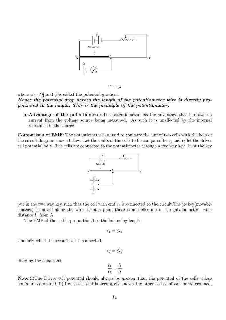
Comparison of EMF: The potentiometer can used to compare the emf of two cells with the help ofthe circuit diagram shown below. Let the emf’s of the cells to be compared be ε1 and ε2 let the drivercell potential be V. The cells are connected to the potentiometer through a two way key. First the key
put in the two way key such that the cell with emf ε1 is connected to the circuit.The jockey(movablecontact) is moved along the wire till at a point there is no deflection in the galvanometer , at adistance l1 from A.
The EMF of the cell is proportional to the balancing length
ε1 = φl1
similarly when the second cell is connected
ε2 = φl2
dividing the equationsε1ε2
=l1l2
Note:(i)The Driver cell potential should always be greater than the potential of the cells whoseemf’s are compared.(ii)If one cells emf is accurately known the other cells emf can be determined.
11
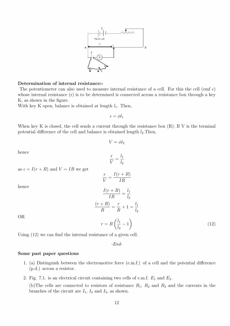
Determination of internal resistance:-The potentiometer can also used to measure internal resistance of a cell. For this the cell (emf ε)
whose internal resistance (r) is to be determined is connected across a resistance box through a keyK, as shown in the figure.With key K open, balance is obtained at length l1. Then,
ε = φl1
When key K is closed, the cell sends a current through the resistance box (R). If V is the terminalpotential difference of the cell and balance is obtained length l2.Then,
V = φl2
henceε
V=l1l2
as ε = I(r +R) and V = IR we getε
V=I(r +R)
IR
henceI(r +R)
IR=l1l2
(r +R)
R=
r
R+ 1 =
l1l2
OR
r = R
(l1l2− 1
)(12)
Using (12) we can find the internal resistance of a given cell.
-End-
Some past paper questions
1. (a) Distinguish between the electromotive force (e.m.f.) of a cell and the potential difference(p.d.) across a resistor.
2. Fig. 7.1. is an electrical circuit containing two cells of e.m.f. E1 and E2.
(b)The cells are connected to resistors of resistance R1, R2 and R3 and the currents in thebranches of the circuit are I1, I2 and I3, as shown.
12
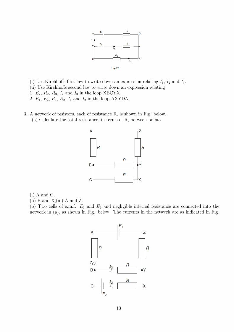
(i) Use Kirchhoffs first law to write down an expression relating I1, I2 and I3.(ii) Use Kirchhoffs second law to write down an expression relating1. E2, R2, R3, I2 and I3 in the loop XBCYX2. E1, E2, R1, R2, I1 and I2 in the loop AXYDA.
3. A network of resistors, each of resistance R, is shown in Fig. below.(a) Calculate the total resistance, in terms of R, between points
(i) A and C,(ii) B and X,(iii) A and Z.(b) Two cells of e.m.f. E1 and E2 and negligible internal resistance are connected into thenetwork in (a), as shown in Fig. below. The currents in the network are as indicated in Fig.
13
(b)Use Kirchhoffs laws to state the relation (i) between currents I1, I2 and I3,(ii) between E2, R, I2 and I3 in loop BCXYB(iii) between E1, E2, R, I1 and I2 in loop ABCXYZA.
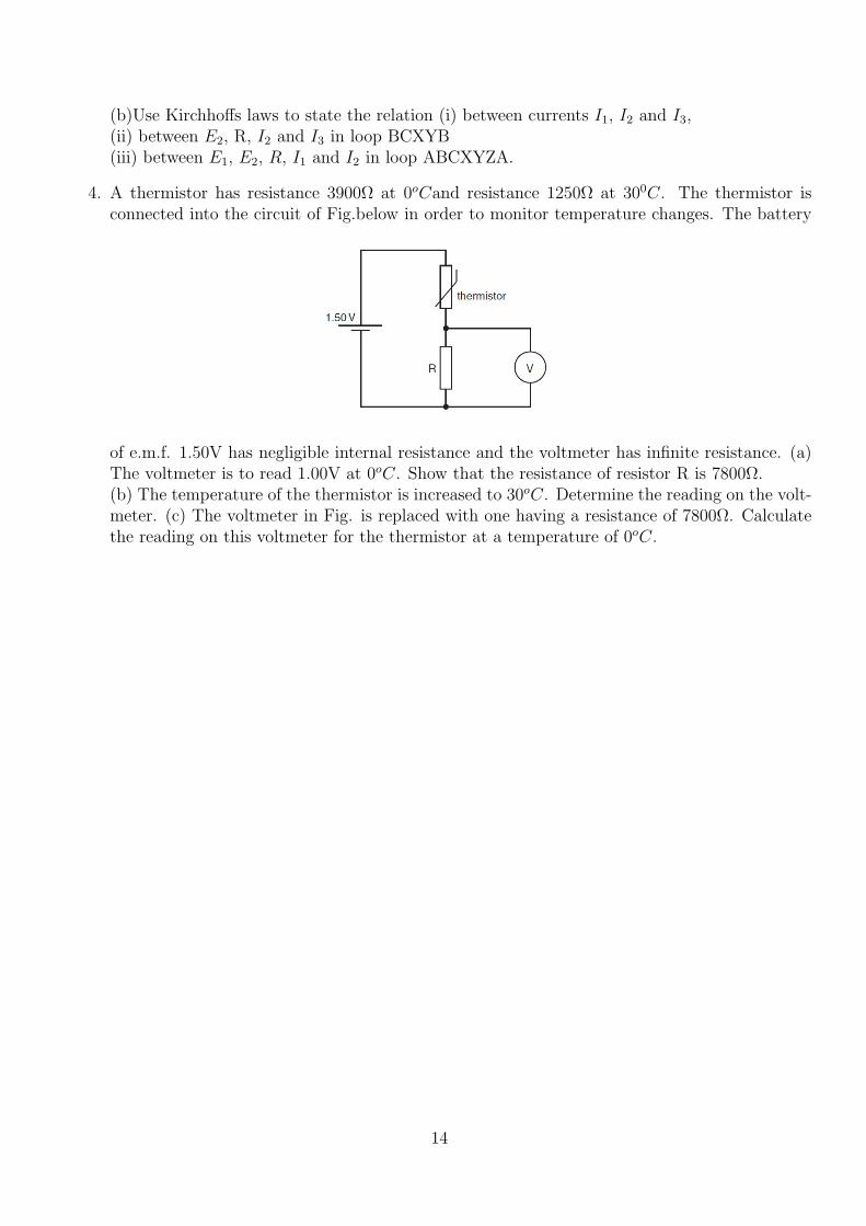
4. A thermistor has resistance 3900Ω at 0oCand resistance 1250Ω at 300C. The thermistor isconnected into the circuit of Fig.below in order to monitor temperature changes. The battery
of e.m.f. 1.50V has negligible internal resistance and the voltmeter has infinite resistance. (a)The voltmeter is to read 1.00V at 0oC. Show that the resistance of resistor R is 7800Ω.(b) The temperature of the thermistor is increased to 30oC. Determine the reading on the volt-meter. (c) The voltmeter in Fig. is replaced with one having a resistance of 7800Ω. Calculatethe reading on this voltmeter for the thermistor at a temperature of 0oC.
14