Embed Size (px)
Citation preview
DC circuit calculations
This worksheet and all related files are licensed under the Creative Commons Attribution License,version 1.0. To view a copy of this license, visit http://creativecommons.org/licenses/by/1.0/, or send aletter to Creative Commons, 559 Nathan Abbott Way, Stanford, California 94305, USA. The terms andconditions of this license allow for free copying, distribution, and/or modification of all licensed works bythe general public.
1
Questions
Question 1
In a series circuit, certain general principles may be stated with regard to quantities of voltage, current,resistance, and power. Complete these sentences, each one describing a fundamental principle of seriescircuits:
“In a series circuit, voltage . . .”
“In a series circuit, current . . .”
“In a series circuit, resistance . . .”
“In a series circuit, power . . .”
For each of these rules, explain why it is true.file i01140
Question 2
Explain, step by step, how to calculate the amount of current (I) that will go through each resistor inthis series circuit, and also the current (I) supplied by the DC voltage source:
R1 R2 R3
1k5 10k 4k7
36 V
file i01236
2
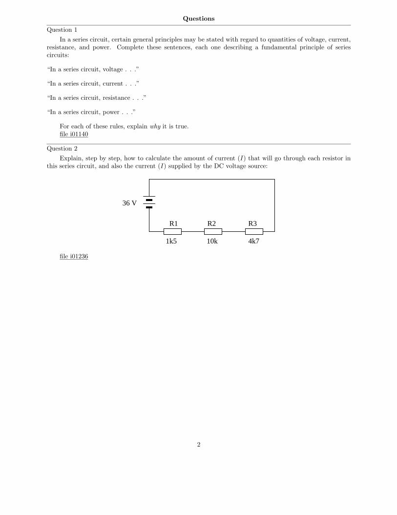
Question 3
Determine the amount of voltage dropped by each resistor in this circuit, if each resistor has a colorcode of Brn, Blk, Red, Gld (assume perfectly precise resistance values – 0% error):
+-
4.5 volts
R1
R2
R3
Also, determine the following information about this circuit:
• Current through each resistor• Power dissipated by each resistor• Ratio of each resistor’s voltage drop to battery voltage ( ER
Ebat
)
• Ratio of each resistor’s resistance to the total circuit resistance ( R
Rtotal
)
file i01181
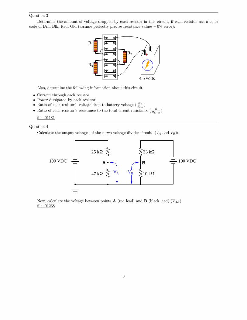
Question 4
Calculate the output voltages of these two voltage divider circuits (VA and VB):
100 VDC
25 kΩ
47 kΩ
A B
VA VB
100 VDC
33 kΩ
10 kΩ
Now, calculate the voltage between points A (red lead) and B (black lead) (VAB).file i01238
3
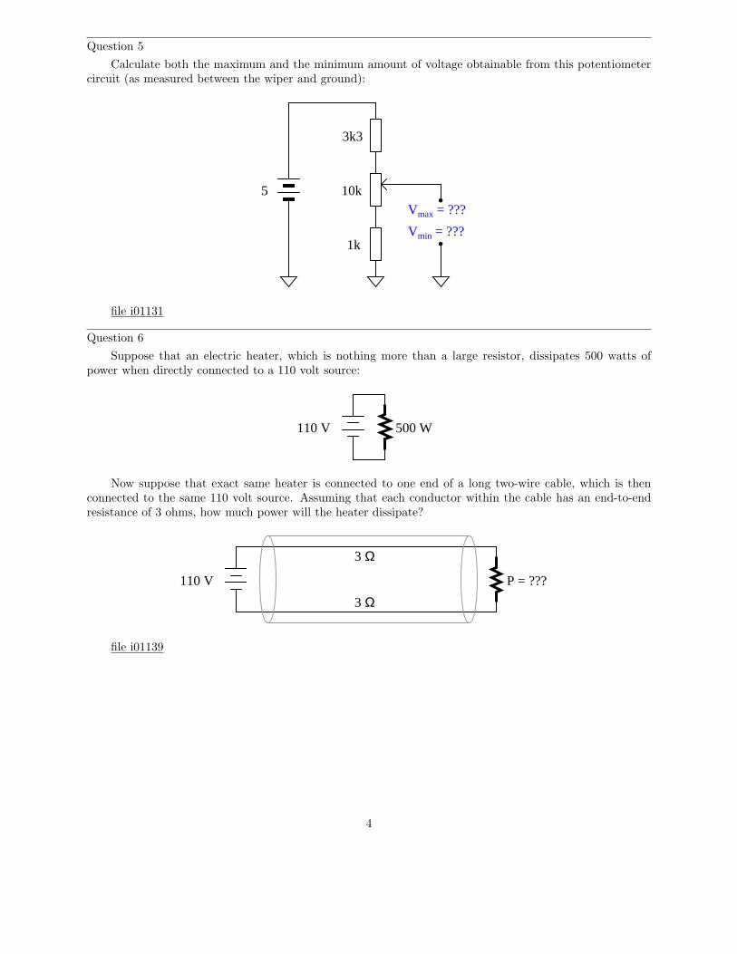
Question 5
Calculate both the maximum and the minimum amount of voltage obtainable from this potentiometercircuit (as measured between the wiper and ground):
3k3
10k
1k
Vmax = ???
Vmin = ???
5
file i01131
Question 6
Suppose that an electric heater, which is nothing more than a large resistor, dissipates 500 watts ofpower when directly connected to a 110 volt source:
110 V 500 W
Now suppose that exact same heater is connected to one end of a long two-wire cable, which is thenconnected to the same 110 volt source. Assuming that each conductor within the cable has an end-to-endresistance of 3 ohms, how much power will the heater dissipate?
110 V
3 Ω
3 ΩP = ???
file i01139
4
Question 7
Suppose an analog voltmeter has a range of 0 to 10 volts, and an internal resistance of exactly 100 kΩ:
- +
Volts
100 kΩ
05
10
Show how a single resistor could be connected to this voltmeter to extend its range to 0 to 50 volts.Calculate the resistance of this “range” resistor, as well as its necessary power dissipation rating.
file i01138
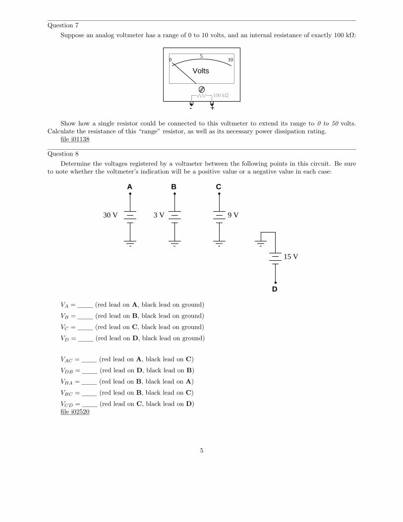
Question 8
Determine the voltages registered by a voltmeter between the following points in this circuit. Be sureto note whether the voltmeter’s indication will be a positive value or a negative value in each case:
A B C
D
30 V 3 V 9 V
15 V
VA = (red lead on A, black lead on ground)
VB = (red lead on B, black lead on ground)
VC = (red lead on C, black lead on ground)
VD = (red lead on D, black lead on ground)
VAC = (red lead on A, black lead on C)
VDB = (red lead on D, black lead on B)
VBA = (red lead on B, black lead on A)
VBC = (red lead on B, black lead on C)
VCD = (red lead on C, black lead on D)file i02520
5
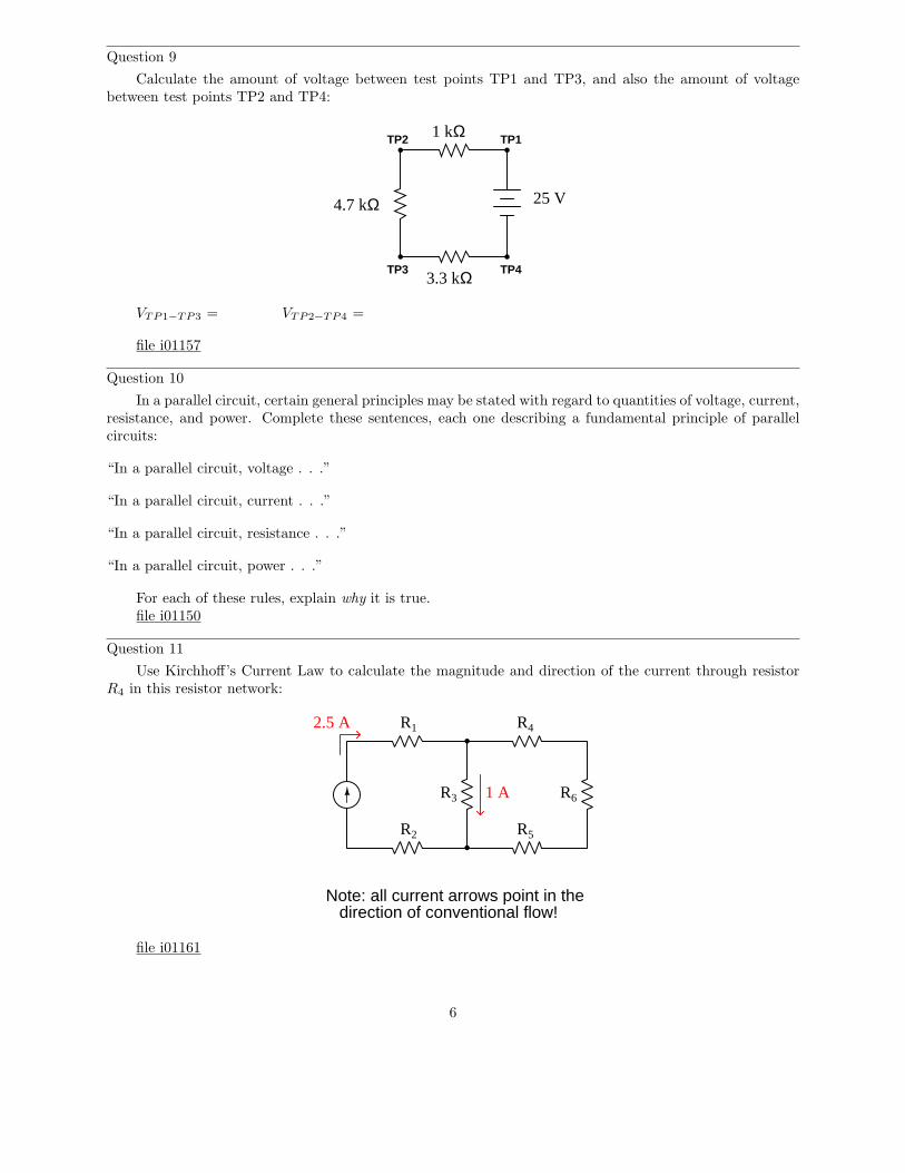
Question 9
Calculate the amount of voltage between test points TP1 and TP3, and also the amount of voltagebetween test points TP2 and TP4:
25 V
1 kΩ
4.7 kΩ
3.3 kΩ
TP1TP2
TP3 TP4
VTP1−TP3 = VTP2−TP4 =
file i01157
Question 10
In a parallel circuit, certain general principles may be stated with regard to quantities of voltage, current,resistance, and power. Complete these sentences, each one describing a fundamental principle of parallelcircuits:
“In a parallel circuit, voltage . . .”
“In a parallel circuit, current . . .”
“In a parallel circuit, resistance . . .”
“In a parallel circuit, power . . .”
For each of these rules, explain why it is true.file i01150
Question 11
Use Kirchhoff’s Current Law to calculate the magnitude and direction of the current through resistorR4 in this resistor network:
R1 R4
R6R3
R2 R5
2.5 A
Note: all current arrows point in thedirection of conventional flow!
1 A
file i01161
6
Question 12
Explain, step by step, how to calculate the amount of current (I) that will go through each resistor inthis parallel circuit, and also the current (I) supplied by the DC voltage source:
R1 R2 R31k5 10k 4k736 V
file i01237
Question 13
Calculate the total amount of current that the battery must supply to this parallel circuit:
10 V500 Ω500 Ω
Now, using Ohm’s Law, calculate total resistance (Rtotal) from total (source) voltage Vtotal and total(source) current Itotal.
file i01149
Question 14
Complete the table of values for this circuit:
V
I
R
P
R1 R2
R1 R2 Total
30 V3k310k
file i01148
7
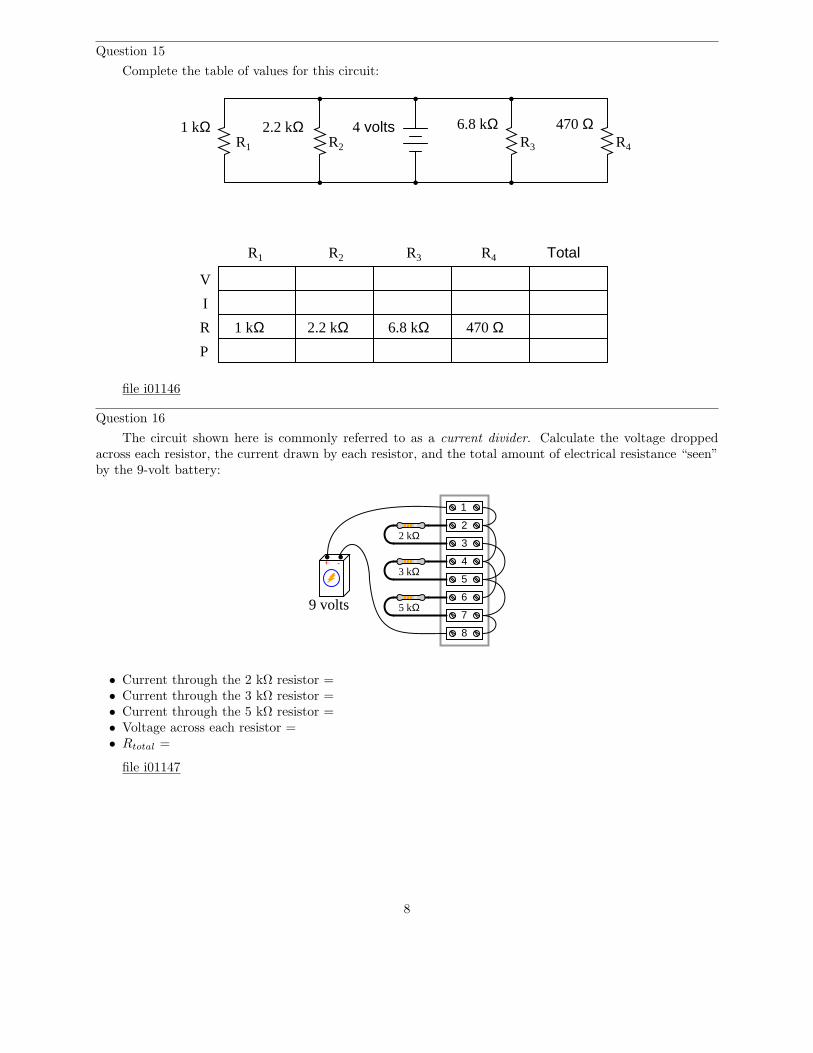
Question 15
Complete the table of values for this circuit:
1 kΩ 2.2 kΩ 470 Ω6.8 kΩ
V
I
R
P
R1 R2 R3 R4
R1 R2 R3 R4 Total
1 kΩ 2.2 kΩ 6.8 kΩ 470 Ω
4 volts
file i01146
Question 16
The circuit shown here is commonly referred to as a current divider. Calculate the voltage droppedacross each resistor, the current drawn by each resistor, and the total amount of electrical resistance “seen”by the 9-volt battery:
+ -3 kΩ
2 kΩ
5 kΩ
1
2
3
4
5
6
7
8
9 volts
• Current through the 2 kΩ resistor =• Current through the 3 kΩ resistor =• Current through the 5 kΩ resistor =• Voltage across each resistor =• Rtotal =
file i01147
8
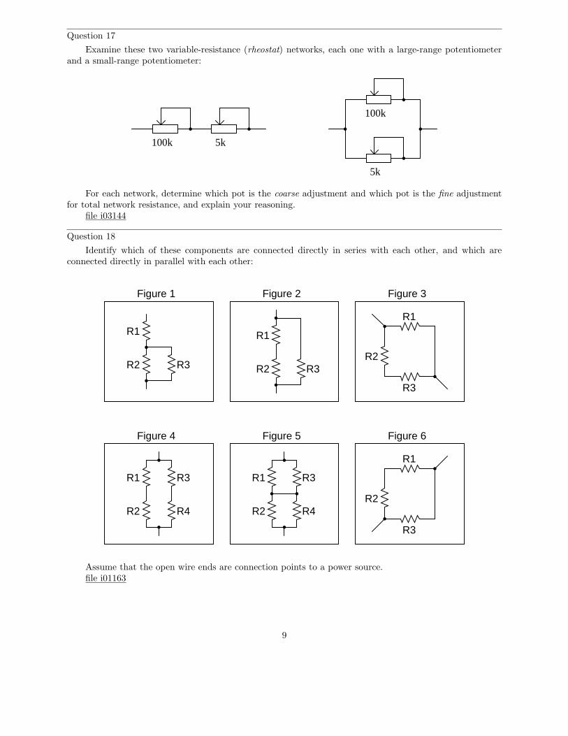
Question 17
Examine these two variable-resistance (rheostat) networks, each one with a large-range potentiometerand a small-range potentiometer:
100k 5k
100k
5k
For each network, determine which pot is the coarse adjustment and which pot is the fine adjustmentfor total network resistance, and explain your reasoning.
file i03144
Question 18
Identify which of these components are connected directly in series with each other, and which areconnected directly in parallel with each other:
Figure 1 Figure 2
R1
R2 R3
Figure 3
R1
R2 R3
R1
R2
R3
Figure 4 Figure 5 Figure 6
R1
R2
R3
R1
R2
R3
R4
R1
R2
R3
R4
Assume that the open wire ends are connection points to a power source.file i01163
9
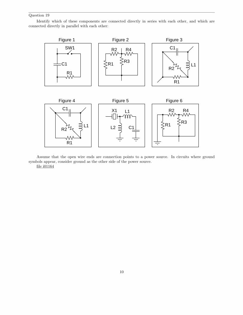
Question 19
Identify which of these components are connected directly in series with each other, and which areconnected directly in parallel with each other:
Figure 1 Figure 2 Figure 3
Figure 4 Figure 5 Figure 6
SW1
C1
R1
R1
R2
R3
R4 C1
L1
R1
R2
C1
L1
R1
R2
X1 L1
L2 C1R1
R2
R3
R4
Assume that the open wire ends are connection points to a power source. In circuits where groundsymbols appear, consider ground as the other side of the power source.
file i01164
10
Question 20
Calculate the resistance between points A and B (RAB) for the following resistor networks:
Figure 1 Figure 2 Figure 3
Figure 4 Figure 5 Figure 6
All resistors 500 Ω
A
B A
B
All resistors 1 kΩ
B
A2 kΩ 5 kΩ
100 Ω 470 Ω
A
B
470 Ω
250 Ω
940 Ω
A
B
All resistors 2.2 kΩ
B
A100 Ω
470 Ω220 Ω
330 Ω
file i01165
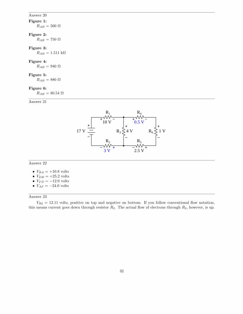
Question 21
Use Kirchhoff’s Voltage Law to calculate the magnitude and polarity of the voltage across resistors R2
and R4 in this resistor network:
17 V
R1
R2
R3
R4
R5
R6
10 V
4 V 1 V
2.5 V
file i01156
11
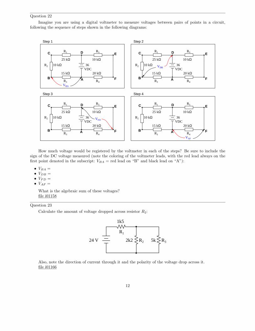
Question 22
Imagine you are using a digital voltmeter to measure voltages between pairs of points in a circuit,following the sequence of steps shown in the following diagrams:
R1
R2
R3
25 kΩ10 kΩ
15 kΩ
AB
C D
36VDC
R4
R5
10 kΩ
20 kΩ
E
F
R1
R2
R3
25 kΩ10 kΩ
15 kΩ
AB
C D
36VDC
R4
R5
10 kΩ
20 kΩ
E
F
R1
R2
R3
25 kΩ10 kΩ
15 kΩ
AB
C D
36VDC
R4
R5
10 kΩ
20 kΩ
E
F
R1
R2
R3
25 kΩ10 kΩ
15 kΩ
AB
C D
36VDC
R4
R5
10 kΩ
20 kΩ
E
F
Step 1 Step 2
Step 3 Step 4
VBA
VDB
VFD
VAF
How much voltage would be registered by the voltmeter in each of the steps? Be sure to include thesign of the DC voltage measured (note the coloring of the voltmeter leads, with the red lead always on thefirst point denoted in the subscript: VBA = red lead on “B” and black lead on “A”):
• VBA =• VDB =• VFD =• VAF =
What is the algebraic sum of these voltages?file i01158
Question 23
Calculate the amount of voltage dropped across resistor R2:
24 V
1k5
2k2 5k
R1
R2 R3
Also, note the direction of current through it and the polarity of the voltage drop across it.file i01166
12
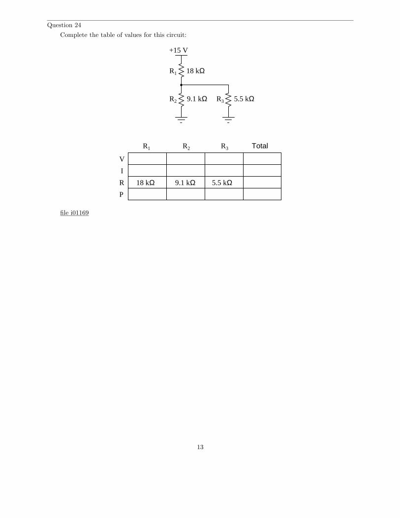
Question 24
Complete the table of values for this circuit:
V
I
R
P
R2 R3
R1 R2 R3 Total
R1
+15 V
18 kΩ
9.1 kΩ 5.5 kΩ
18 kΩ 9.1 kΩ 5.5 kΩ
file i01169
13
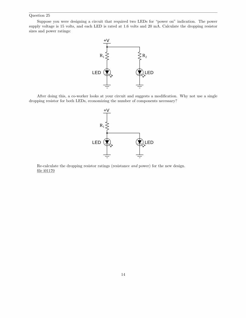
Question 25
Suppose you were designing a circuit that required two LEDs for “power on” indication. The powersupply voltage is 15 volts, and each LED is rated at 1.6 volts and 20 mA. Calculate the dropping resistorsizes and power ratings:
+V
LED LED
R1 R2
After doing this, a co-worker looks at your circuit and suggests a modification. Why not use a singledropping resistor for both LEDs, economizing the number of components necessary?
+V
LED LED
R1
Re-calculate the dropping resistor ratings (resistance and power) for the new design.file i01170
14
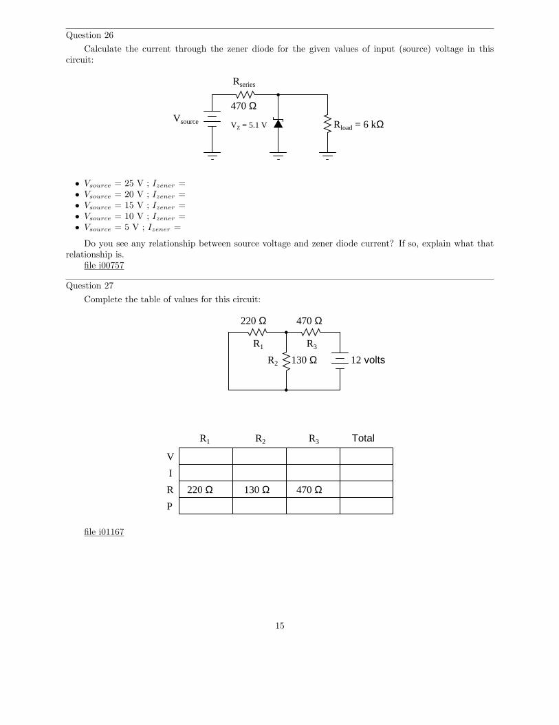
Question 26
Calculate the current through the zener diode for the given values of input (source) voltage in thiscircuit:
Rseries
VZ = 5.1 VVsource
470 Ω
Rload = 6 kΩ
• Vsource = 25 V ; Izener =• Vsource = 20 V ; Izener =• Vsource = 15 V ; Izener =• Vsource = 10 V ; Izener =• Vsource = 5 V ; Izener =
Do you see any relationship between source voltage and zener diode current? If so, explain what thatrelationship is.
file i00757
Question 27
Complete the table of values for this circuit:
V
I
R
P
R2
R3
R1 R2 R3 Total
12 volts
R1
220 Ω
130 Ω
470 Ω
220 Ω 130 Ω 470 Ω
file i01167
15
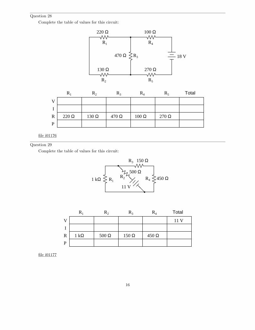
Question 28
Complete the table of values for this circuit:
V
I
R
P
R2
R3
R1 R2 R3 Total
R1
220 Ω
130 Ω
470 Ω
220 Ω 130 Ω 470 Ω
R4 R5
R4
R5
100 Ω
270 Ω
100 Ω 270 Ω
18 V
file i01176
Question 29
Complete the table of values for this circuit:
1 kΩ
V
I
R
P
R1R2
R3
R4
R1 R2 R3 R4 Total
1 kΩ
11 V
500 Ω
150 Ω
450 Ω
500 Ω 150 Ω 450 Ω
11 V
file i01177
16
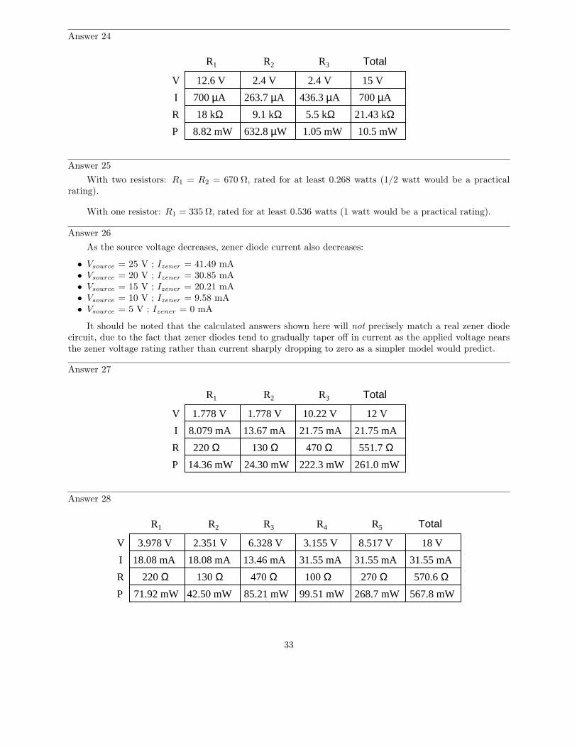
Question 30
Calculate the amount of voltage between points A and B in this circuit. You must sketch polarity marks(+ , −) on the schematic diagram to show the polarity of VAB , as well as show all of your mathematicalwork!
270
1k
2k2 3k31k
A
B
26
file i02527
17
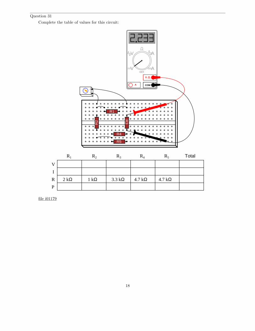
Question 31
Complete the table of values for this circuit:
V
I
R
P
R1 R2 R3 TotalR4 R5
1 kΩ
+-
R5
R1
R2
R3
R4
2 kΩ 3.3 kΩ 4.7 kΩ 4.7 kΩ
COMA
V
V A
AOFF
file i01179
18
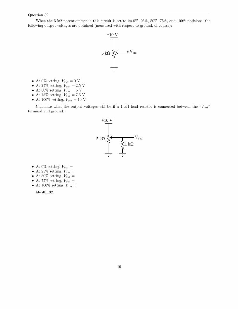
Question 32
When the 5 kΩ potentiometer in this circuit is set to its 0%, 25%, 50%, 75%, and 100% positions, thefollowing output voltages are obtained (measured with respect to ground, of course):
+10 V
Vout5 kΩ
• At 0% setting, Vout = 0 V• At 25% setting, Vout = 2.5 V• At 50% setting, Vout = 5 V• At 75% setting, Vout = 7.5 V• At 100% setting, Vout = 10 V
Calculate what the output voltages will be if a 1 kΩ load resistor is connected between the “Vout”terminal and ground:
+10 V
Vout5 kΩ1 kΩ
• At 0% setting, Vout =• At 25% setting, Vout =• At 50% setting, Vout =• At 75% setting, Vout =• At 100% setting, Vout =
file i01132
19
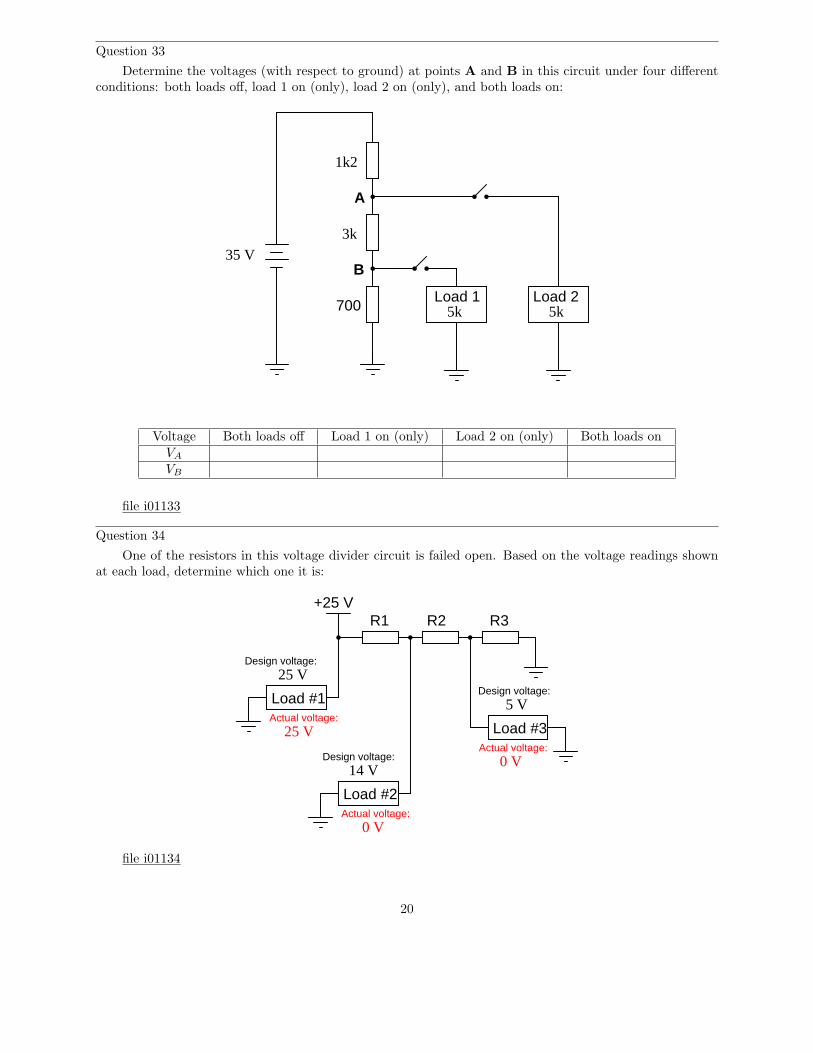
Question 33
Determine the voltages (with respect to ground) at points A and B in this circuit under four differentconditions: both loads off, load 1 on (only), load 2 on (only), and both loads on:
1k2
3k
700 5k 5kLoad 1 Load 2
35 V
A
B
Voltage Both loads off Load 1 on (only) Load 2 on (only) Both loads onVA
VB
file i01133
Question 34
One of the resistors in this voltage divider circuit is failed open. Based on the voltage readings shownat each load, determine which one it is:
+25 VR1 R2 R3
Load #1
Load #2
Load #3
Design voltage:25 V
Actual voltage:25 V
Design voltage:
Actual voltage:Design voltage:
Actual voltage:
14 V
5 V
0 V
0 V
file i01134
20
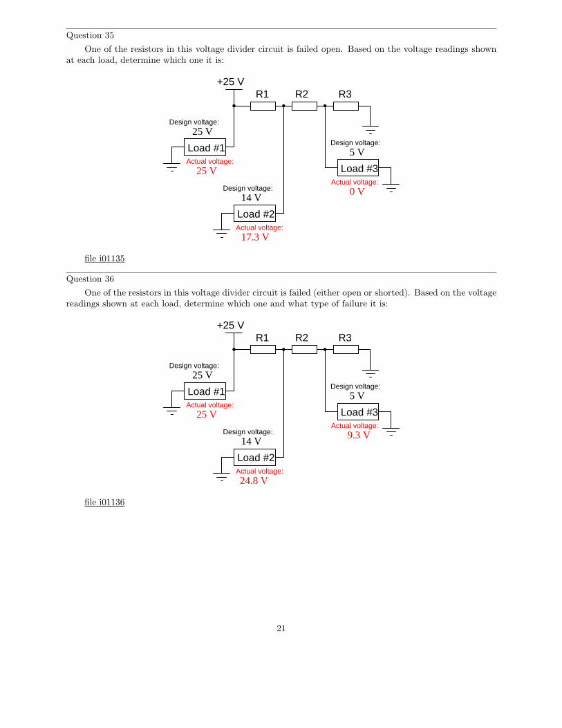
Question 35
One of the resistors in this voltage divider circuit is failed open. Based on the voltage readings shownat each load, determine which one it is:
+25 VR1 R2 R3
Load #1
Load #2
Load #3
Design voltage:25 V
Actual voltage:25 V
Design voltage:
Actual voltage:Design voltage:
Actual voltage:
14 V
5 V
0 V
17.3 V
file i01135
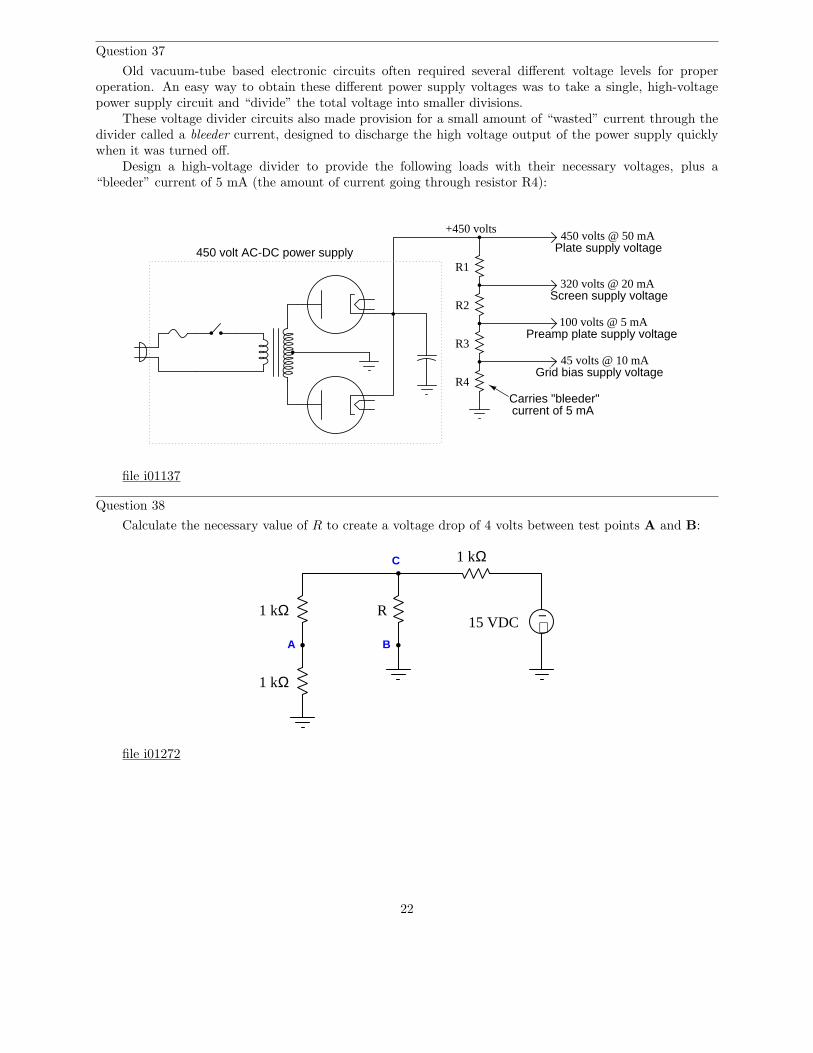
Question 36
One of the resistors in this voltage divider circuit is failed (either open or shorted). Based on the voltagereadings shown at each load, determine which one and what type of failure it is:
+25 VR1 R2 R3
Load #1
Load #2
Load #3
Design voltage:25 V
Actual voltage:25 V
Design voltage:
Actual voltage:Design voltage:
Actual voltage:
14 V
5 V
9.3 V
24.8 V
file i01136
21
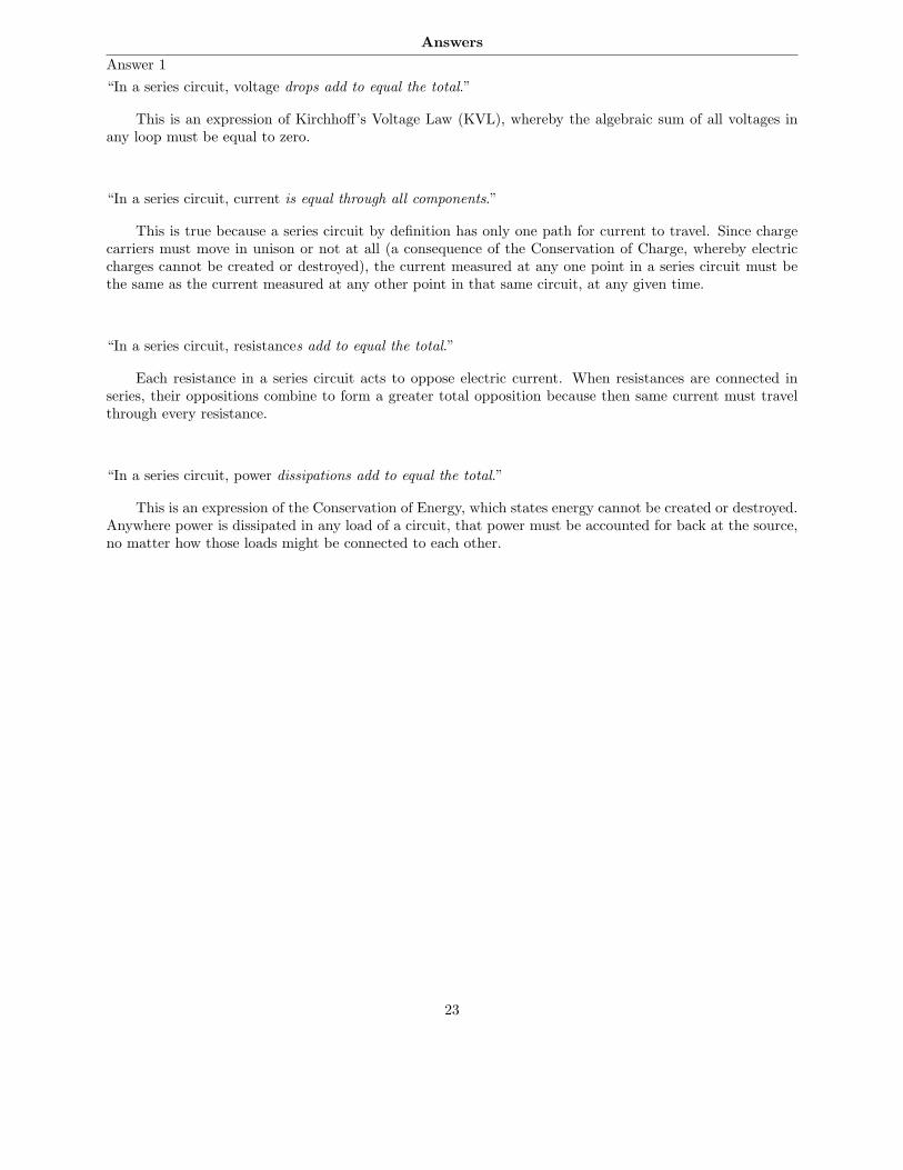
Question 37
Old vacuum-tube based electronic circuits often required several different voltage levels for properoperation. An easy way to obtain these different power supply voltages was to take a single, high-voltagepower supply circuit and “divide” the total voltage into smaller divisions.
These voltage divider circuits also made provision for a small amount of “wasted” current through thedivider called a bleeder current, designed to discharge the high voltage output of the power supply quicklywhen it was turned off.
Design a high-voltage divider to provide the following loads with their necessary voltages, plus a“bleeder” current of 5 mA (the amount of current going through resistor R4):
+450 volts
R1
R2
R3
R4
current of 5 mACarries "bleeder"
450 volts @ 50 mA
320 volts @ 20 mA
100 volts @ 5 mA
45 volts @ 10 mA
450 volt AC-DC power supply Plate supply voltage
Screen supply voltage
Preamp plate supply voltage
Grid bias supply voltage
file i01137
Question 38
Calculate the necessary value of R to create a voltage drop of 4 volts between test points A and B:
+−
1 kΩ
1 kΩ
1 kΩ
R
A B
C
15 VDC
file i01272
22
Answers
Answer 1
“In a series circuit, voltage drops add to equal the total.”
This is an expression of Kirchhoff’s Voltage Law (KVL), whereby the algebraic sum of all voltages inany loop must be equal to zero.
“In a series circuit, current is equal through all components.”
This is true because a series circuit by definition has only one path for current to travel. Since chargecarriers must move in unison or not at all (a consequence of the Conservation of Charge, whereby electriccharges cannot be created or destroyed), the current measured at any one point in a series circuit must bethe same as the current measured at any other point in that same circuit, at any given time.
“In a series circuit, resistances add to equal the total.”
Each resistance in a series circuit acts to oppose electric current. When resistances are connected inseries, their oppositions combine to form a greater total opposition because then same current must travelthrough every resistance.
“In a series circuit, power dissipations add to equal the total.”
This is an expression of the Conservation of Energy, which states energy cannot be created or destroyed.Anywhere power is dissipated in any load of a circuit, that power must be accounted for back at the source,no matter how those loads might be connected to each other.
23
Answer 2
First we need to identify all the relevant principles for series circuits:
• The algebraic sum of all voltages in the circuit will be equal to zero (Kirchhoff’s Voltage Law)• Current is common throughout a series circuit, because there is only one path for current in the entire
circuit• Resistances add in series
We know the voltage of the source and the resistance of the three loads. However, we cannot simplyapply Ohm’s Law at this point because the source voltage is not impressed entirely on any one of the loads –rather the source voltage will be split up proportionately amongst the three loads in accordance with KVL.It is important to always apply Ohm’s Law in context: V = IR is true only if V , I, and R apply to the samecomponent or set of components. Here, the 36 volts of the source applies to all three resistors, not to anyone resistor.
However, we may apply the principle of resistances adding in series to arrive at a total resistance valuefor the circuit, which we may then apply to total voltage to find total current. Adding up the three resistors’values, we get a total resistance of Rtotal = 1500 + 10000 + 4700 = 16200 ohms. Total circuit current is thencalculated as follows:
I =V
R=
36 V
16200 Ω= 2.222 mA
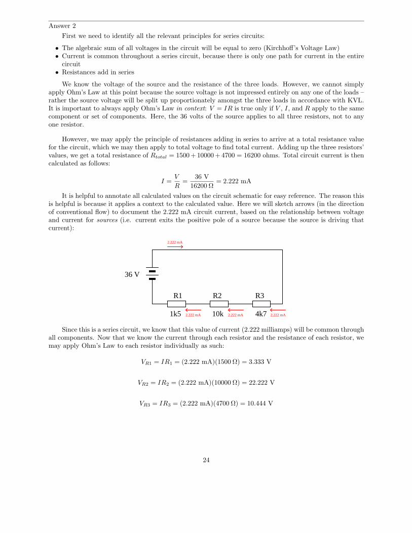
It is helpful to annotate all calculated values on the circuit schematic for easy reference. The reason thisis helpful is because it applies a context to the calculated value. Here we will sketch arrows (in the directionof conventional flow) to document the 2.222 mA circuit current, based on the relationship between voltageand current for sources (i.e. current exits the positive pole of a source because the source is driving thatcurrent):
R1 R2 R3
1k5 10k 4k7
36 V
2.222 mA
2.222 mA 2.222 mA 2.222 mA
Since this is a series circuit, we know that this value of current (2.222 milliamps) will be common throughall components. Now that we know the current through each resistor and the resistance of each resistor, wemay apply Ohm’s Law to each resistor individually as such:
VR1 = IR1 = (2.222 mA)(1500 Ω) = 3.333 V
VR2 = IR2 = (2.222 mA)(10000 Ω) = 22.222 V
VR3 = IR3 = (2.222 mA)(4700 Ω) = 10.444 V
24
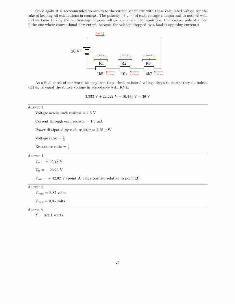
Once again it is recommended to annotate the circuit schematic with these calculated values, for thesake of keeping all calculations in context. The polarity (+ , −) of each voltage is important to note as well,and we know this by the relationship between voltage and current for loads (i.e. the positive pole of a loadis the one where conventional flow enters, because the voltage dropped by a load is opposing current):
R1 R2 R3
1k5 10k 4k7
36 V
2.222 mA
2.222 mA 2.222 mA 2.222 mA
3.333 V 10.444 V22.222 V
As a final check of our work, we may sum these three resistors’ voltage drops to ensure they do indeedadd up to equal the source voltage in accordance with KVL:
3.333 V + 22.222 V + 10.444 V = 36 V
Answer 3
Voltage across each resistor = 1.5 V
Current through each resistor = 1.5 mA
Power dissipated by each resistor = 2.25 mW
Voltage ratio = 1
3
Resistance ratio = 1
3
Answer 4
VA = + 65.28 V
VB = + 23.26 V
VAB = + 42.02 V (point A being positive relative to point B)
Answer 5
Vmax = 3.85 volts
Vmin = 0.35 volts
Answer 6
P = 321.1 watts
25
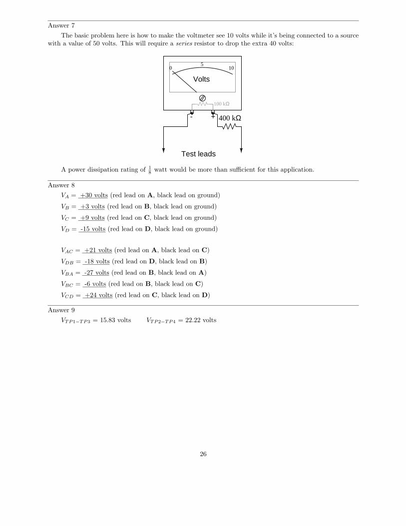
Answer 7
The basic problem here is how to make the voltmeter see 10 volts while it’s being connected to a sourcewith a value of 50 volts. This will require a series resistor to drop the extra 40 volts:
- +
Volts
100 kΩ
05
10
Test leads
400 kΩ
A power dissipation rating of 1
8watt would be more than sufficient for this application.
Answer 8
VA = +30 volts (red lead on A, black lead on ground)
VB = +3 volts (red lead on B, black lead on ground)
VC = +9 volts (red lead on C, black lead on ground)
VD = -15 volts (red lead on D, black lead on ground)
VAC = +21 volts (red lead on A, black lead on C)
VDB = -18 volts (red lead on D, black lead on B)
VBA = -27 volts (red lead on B, black lead on A)
VBC = -6 volts (red lead on B, black lead on C)
VCD = +24 volts (red lead on C, black lead on D)
Answer 9
VTP1−TP3 = 15.83 volts VTP2−TP4 = 22.22 volts
26
Answer 10
“In a parallel circuit, voltage is equal across all components.”
This is true because a parallel circuit by definition is one where the constituent components all sharethe same two equipotential points.
“In a parallel circuit, currents add to equal the total.”
This is an expression of Kirchhoff’s Current Law (KCL), whereby the algebraic sum of all currentsentering and exiting a node must be equal to zero.
“In a parallel circuit, resistances diminish to equal the total.”
Each resistance in a parallel circuit provides another path for electric current. When resistances areconnected in parallel, their combined total paths provide less opposition than any single path because thecurrent is able to split up and proportionately follow these alternative paths.
“In a parallel circuit, power dissipations add to equal the total.”
This is an expression of the Conservation of Energy, which states energy cannot be created or destroyed.Anywhere power is dissipated in any load of a circuit, that power must be accounted for back at the source,no matter how those loads might be connected to each other.
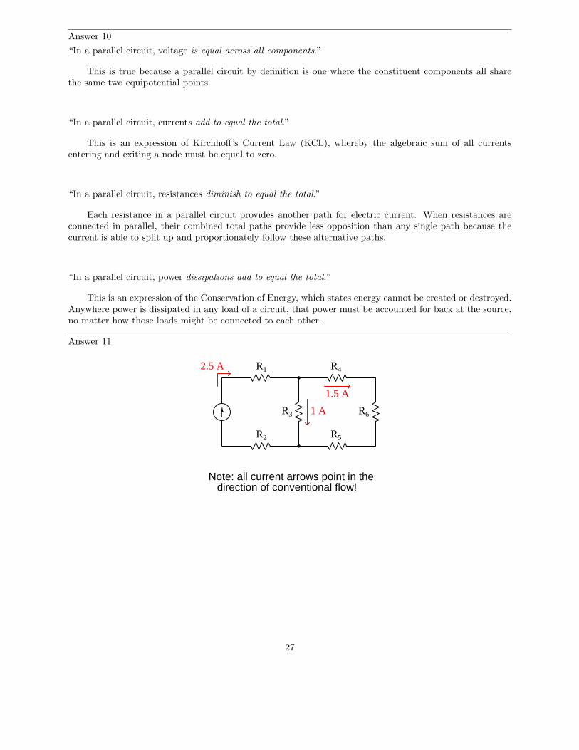
Answer 11
R1 R4
R6R3
R2 R5
2.5 A
Note: all current arrows point in thedirection of conventional flow!
1 A
1.5 A
27
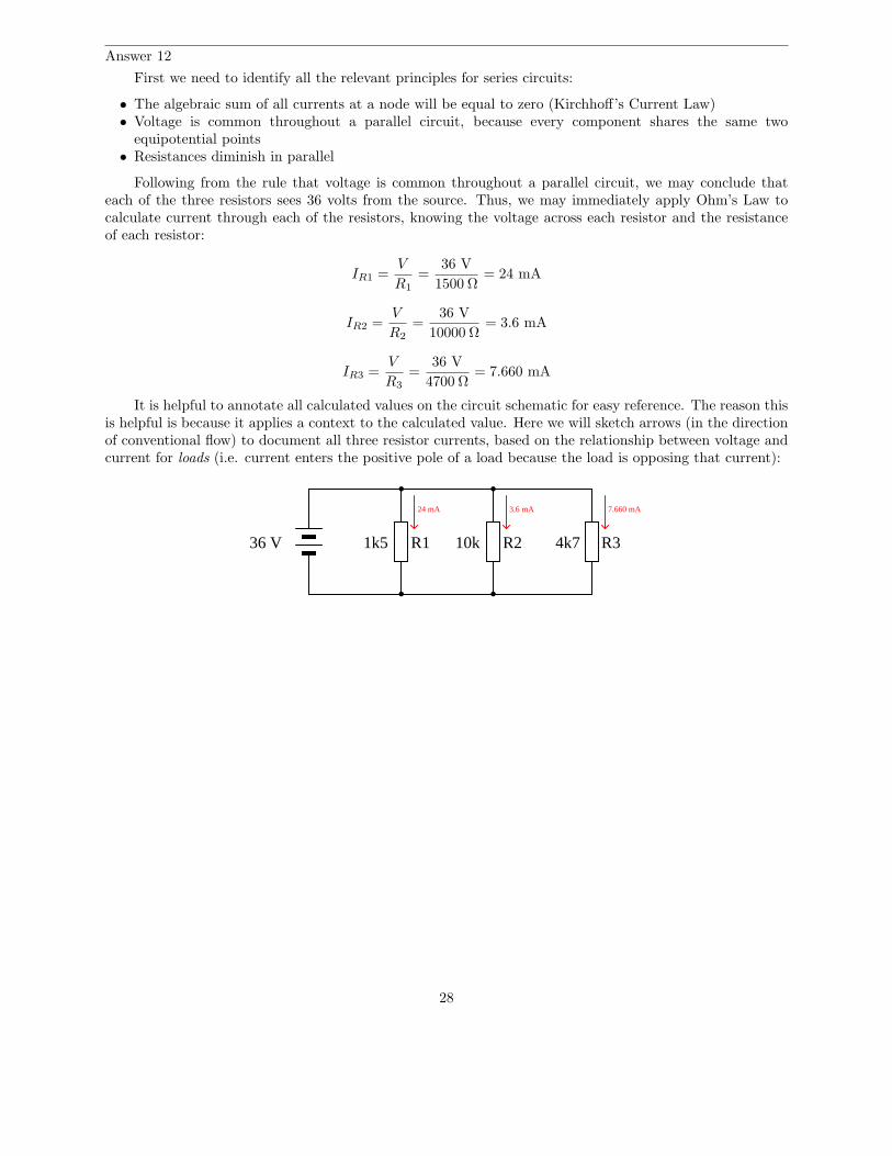
Answer 12
First we need to identify all the relevant principles for series circuits:
• The algebraic sum of all currents at a node will be equal to zero (Kirchhoff’s Current Law)• Voltage is common throughout a parallel circuit, because every component shares the same two
equipotential points• Resistances diminish in parallel
Following from the rule that voltage is common throughout a parallel circuit, we may conclude thateach of the three resistors sees 36 volts from the source. Thus, we may immediately apply Ohm’s Law tocalculate current through each of the resistors, knowing the voltage across each resistor and the resistanceof each resistor:
IR1 =V
R1
=36 V
1500 Ω= 24 mA
IR2 =V
R2
=36 V
10000 Ω= 3.6 mA
IR3 =V
R3
=36 V
4700 Ω= 7.660 mA
It is helpful to annotate all calculated values on the circuit schematic for easy reference. The reason thisis helpful is because it applies a context to the calculated value. Here we will sketch arrows (in the directionof conventional flow) to document all three resistor currents, based on the relationship between voltage andcurrent for loads (i.e. current enters the positive pole of a load because the load is opposing that current):
R1 R2 R31k5 10k 4k736 V
24 mA 3.6 mA 7.660 mA
28
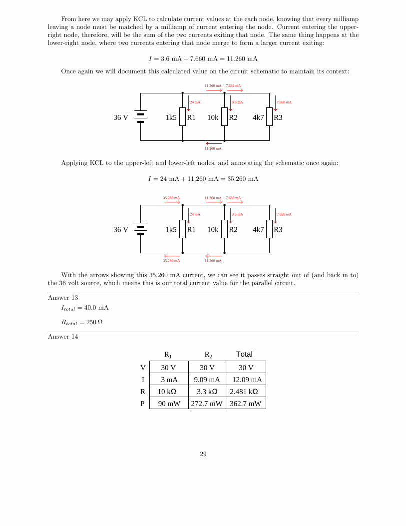
From here we may apply KCL to calculate current values at the each node, knowing that every milliampleaving a node must be matched by a milliamp of current entering the node. Current entering the upper-right node, therefore, will be the sum of the two currents exiting that node. The same thing happens at thelower-right node, where two currents entering that node merge to form a larger current exiting:
I = 3.6 mA + 7.660 mA = 11.260 mA
Once again we will document this calculated value on the circuit schematic to maintain its context:
R1 R2 R31k5 10k 4k736 V
24 mA 3.6 mA 7.660 mA
7.660 mA11.260 mA
11.260 mA
Applying KCL to the upper-left and lower-left nodes, and annotating the schematic once again:
I = 24 mA + 11.260 mA = 35.260 mA
R1 R2 R31k5 10k 4k736 V
24 mA 3.6 mA 7.660 mA
7.660 mA11.260 mA
11.260 mA
35.260 mA
35.260 mA
With the arrows showing this 35.260 mA current, we can see it passes straight out of (and back in to)the 36 volt source, which means this is our total current value for the parallel circuit.
Answer 13
Itotal = 40.0 mA
Rtotal = 250 Ω
Answer 14
V
I
R
P
R1 R2 Total
10 kΩ 3.3 kΩ
30 V
2.481 kΩ12.09 mA
30 V 30 V
3 mA 9.09 mA
90 mW 272.7 mW 362.7 mW
29
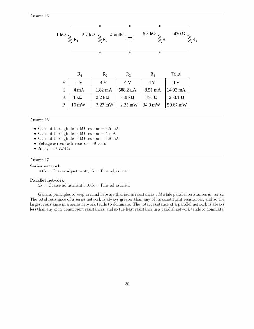
Answer 15
1 kΩ 2.2 kΩ 470 Ω6.8 kΩ
V
I
R
P
R1 R2 R3 R4
R1 R2 R3 R4 Total
1 kΩ 2.2 kΩ 6.8 kΩ 470 Ω
4 volts
4 V4 V4 V4 V4 V
4 mA 1.82 mA 588.2 µA 8.51 mA
268.1 Ω14.92 mA
59.67 mW16 mW 7.27 mW 2.35 mW 34.0 mW
Answer 16
• Current through the 2 kΩ resistor = 4.5 mA• Current through the 3 kΩ resistor = 3 mA• Current through the 5 kΩ resistor = 1.8 mA• Voltage across each resistor = 9 volts• Rtotal = 967.74 Ω
Answer 17
Series network
100k = Coarse adjustment ; 5k = Fine adjustment
Parallel network
5k = Coarse adjustment ; 100k = Fine adjustment
General principles to keep in mind here are that series resistances add while parallel resistances diminish.The total resistance of a series network is always greater than any of its constituent resistances, and so thelargest resistance in a series network tends to dominate. The total resistance of a parallel network is alwaysless than any of its constituent resistances, and so the least resistance in a parallel network tends to dominate.
30
Answer 18
Figure 1:
R2 in parallel with R3.
Figure 2:
R1 in series with R2.
Figure 3:
R2 in series with R3.
Figure 4:
R1 in series with R2; R3 in series with R4.
Figure 5:
R1 in parallel with R3; R2 in parallel with R4.
Figure 6:
R1 in series with R2.
Answer 19
Figure 1:
R1 in series with SW1.
Figure 2:
R1 in series with R2; R3 in parallel with R4.
Figure 3:
R1 parallel with R2.
Figure 4:
R1 parallel with R2.
Figure 5:
L1 in series with C1.
Figure 6:
R3 in parallel with R4.
31
Answer 20
Figure 1:
RAB = 500 Ω
Figure 2:
RAB = 750 Ω
Figure 3:
RAB = 1.511 kΩ
Figure 4:
RAB = 940 Ω
Figure 5:
RAB = 880 Ω
Figure 6:
RAB = 80.54 Ω
Answer 21
17 V
R1
R2
R3
R4
R5
R6
10 V
3 V
4 V 1 V
2.5 V
0.5 V
Answer 22
• VBA = +10.8 volts• VDB = +25.2 volts• VFD = −12.0 volts• VAF = −24.0 volts
Answer 23
VR2 = 12.11 volts, positive on top and negative on bottom. If you follow conventional flow notation,this means current goes down through resistor R2. The actual flow of electrons through R2, however, is up.
32
Answer 24
V
I
R
P
R1 R2 R3 Total
18 kΩ 9.1 kΩ 5.5 kΩ
15 V
700 µA700 µA
12.6 V 2.4 V 2.4 V
263.7 µA 436.3 µA
21.43 kΩ8.82 mW 632.8 µW 1.05 mW 10.5 mW
Answer 25
With two resistors: R1 = R2 = 670 Ω, rated for at least 0.268 watts (1/2 watt would be a practicalrating).
With one resistor: R1 = 335 Ω, rated for at least 0.536 watts (1 watt would be a practical rating).
Answer 26
As the source voltage decreases, zener diode current also decreases:
• Vsource = 25 V ; Izener = 41.49 mA• Vsource = 20 V ; Izener = 30.85 mA• Vsource = 15 V ; Izener = 20.21 mA• Vsource = 10 V ; Izener = 9.58 mA• Vsource = 5 V ; Izener = 0 mA
It should be noted that the calculated answers shown here will not precisely match a real zener diodecircuit, due to the fact that zener diodes tend to gradually taper off in current as the applied voltage nearsthe zener voltage rating rather than current sharply dropping to zero as a simpler model would predict.
Answer 27
V
I
R
P
R1 R2 R3 Total
220 Ω 130 Ω 470 Ω
12 V
21.75 mA
551.7 Ω21.75 mA
1.778 V 1.778 V 10.22 V
8.079 mA 13.67 mA
24.30 mW14.36 mW 222.3 mW 261.0 mW
Answer 28
V
I
R
P
R1 R2 R3 Total
220 Ω 130 Ω 470 Ω
R4 R5
100 Ω 270 Ω
18 V
31.55 mA31.55 mA31.55 mA
3.155 V 8.517 V
268.7 mW99.51 mW
6.328 V
85.21 mW
13.46 mA18.08 mA 18.08 mA
3.978 V 2.351 V
71.92 mW 42.50 mW
570.6 Ω567.8 mW
33
Answer 29
V
I
R
P
R1 R2 R3 R4 Total
1 kΩ 500 Ω 150 Ω 450 Ω
11 V
875 Ω12.57 mA
4.714 V
4.714 mA
3.536 V1.179 V
7.857 mA7.857 mA12.57 mA
6.286 V
138.3 mW79.02 mW22.22 mW 27.78 mW9.26 mW
Answer 30
VAB = 9.198 volts, A positive and B negative.
270
1k
2k2 3k31k
A
B
26
7.24 mA
7.24 V
7.24 V
9.56 V
1.96 V
The voltage between points A and B is the supply voltage (26 volts) minus the voltage drops across the1k and parallel subnetwork resistors. Alternatively, one could calculate VAB by adding the voltage drops ofthe 1k and 270 ohm resistors.
The latter solution makes it easiest to see the polarity of VAB : noting how the voltage drops across the1k and 270 ohm resistors are additive, we see point A being the most positive and point B being the mostnegative.
Answer 31
V
I
R
P
R1 R2 R3 TotalR4 R5
1 kΩ2 kΩ 3.3 kΩ 4.7 kΩ 4.7 kΩ
2.233 V
676.7 µA
1.511 mW
1.590 V 1.590 V
338.3 µA 338.3 µA
538.0 µW 538.0 µW
676.6 mV4.500 V 4.500 V
676.7 µA2.250 mA
457.9 µW10.12 mW
2.927 mA
13.17 mW
1.538 kΩ
34
Answer 32
• At 0% setting, Vout = 0 V• At 25% setting, Vout = 1.29 V• At 50% setting, Vout = 2.22 V• At 75% setting, Vout = 3.87 V• At 100% setting, Vout = 10 V
Answer 33
Voltage Both loads off Load 1 on (only) Load 2 on (only) Both loads onVA 26.4 volts 26.3 volts 22.4 volts 22.3 voltsVB 5 volts 4.46 volts 4.23 volts 3.78 volts
Answer 34
Resistor R1 has failed open. This is evident because only load #1 is receiving any power; the other twoloads are completely “dead”.
Answer 35
Resistor R2 has failed open. We can tell this because load #3 is receiving no power at all while load#2 is being over-powered.
Answer 36
Resistor R1 has failed (partially) shorted. We can tell this because both loads #2 and #3 are beingover-powered.
Answer 37
The key to calculating all resistor values is to determine how much voltage each one must drop and howmuch current each one must carry. The current question may be answered by applying Kirchhoff’s CurrentLaw (KCL) to each of the nodes in the circuit, while the voltage question may be answered by calculatingthe voltage difference between each pair of supply lines to the tube circuit.
• R1 = 3.25 kΩ• R2 = 11 kΩ• R3 = 3.67 kΩ• R4 = 9 kΩ
Answer 38
R = 2.667 kΩ
35


![Chemical calculations in medicinevyuka-data.lf3.cuni.cz/CVSE1M0001/calculations 17 10 2012(5083f3… · Calculate volume of the sol. containing 4 mmol of Cl-. [20ml] Homework •](https://img.pdfslide.us/doc/110x75/5e8cf644de764939105b960b/chemical-calculations-in-medicinevyuka-datalf3cuniczcvse1m0001calculations.jpg)