Embed Size (px)
Citation preview
GEK-11028
INSTRUCTIONS
DC-3032
SCR POWER UNIT ASSEMBLY 5-60 HP, THREE PHASE
USED WITH
ADJUSTA LE SPEED DRIVES
GENERAL@ ELECTRIC
WARNING SINCE HIGH VOLTAGES ARE PRESENT IN MANY LOCATIONS WITHIN THE SCR DRIVE, EXTREME CARE MUST BE EXERCISED IN THE SELECTION AND USE OF TEST INSTRUMENTS. WHETHER THE AC SUPPLY IS GROUNDED OR NOT, HIGH VOLTAGES TO GROUND WILL BE PRESENT AT MANY POINTS. OPERA- TORS SHOULD NOT STAND ON GROUNDED SURFACES OR BE IN CONTACT WITH GROUND WHEN AP- PLYING TEST INSTRUMENTS TO TEST POINTS. EXTREME CARE SHOULD BE TAKEN WHILE ATTEMP- TING TO ADJUST, TROUBLESHOOT OR MAINTAIN ANY DRIVE SYSTEM DESCRIBED HEREIN.
CONTENTS
Page INTRODUCTION/RECEIVING AND STORAGE/MAINTENANCE . . . . . . . . . . . . . . . . . . . . . . . . . . . . . . . . . . . . . . . . . . . . . . . . . . . . . . . . . . . . . . . . . . . . . . . . . . . . . 1 DESCRIPTION . . . . . . . . . . . . . . . . . . . . . . . . . . . . . . . . . . . . . . . . . . . . . . . . . . . . . . . . . . . . . . . . . . . . . . . . . . . . . . . . . . . . . . . . . . . . . . . . . . . . . . . . . . . . . . . . . . . . . . . . ....................................... 2 SPECIFICATIONS . . . . . . . . . . . . . . . . . . . . . . . . . . . . . . . . . . . . . . . . . . . . . . . . . . . . . . . . . . . . . . . . . . . . . . . . . . . . . . . . . . . . . . . . . . . . . . . . . . . . . . . . . . . . . . . . . . . . . . . . ................................. 3 HOW THE SCR POWER UNIT WORKS . . . . . . . . . . . . . . . . . . . . . . . . . . . . . . . . . . . . . . . . . . . . . . . . . . . . . . . . . . . . . . . . . . . . . . . . . . . . . . . . . . . . . . . . . . . . . . . . . . . . . . . . . . . . . . . . . . . . . . . . .. 4 INSTALLATION PRECAUTIONS/INSTALLATION . . . . . . . . . . . . . . . . . . . . . . . . . . . . . . . . . . . . . . . . . . . . . . . . . . . . . . . . . . . . . . . . . . . . . . . . . . . . . . . . . . . . . . . . . . . . . . . . . . . 8 INTERCONNECTION WIRING . . . . . . . . . . . . . . . . . . . . . . . . . . . . . . . . . . . . . . . . . . . . . . . . . . . . . . . . . . . . . . . . . . . . . . . . . . . . . . . . . . . . . . . . . . . . . . . . . . . . . . . . . . . . . . . . . . . . . . . . ............ 10 SETUP AND ADJUSTMENT . . . . . . . . . . . . . . . . . . . . . . . . . . . . . . . . . . . . . . . . . . . . . . . . . . . . . . . . . . . . . . . . . . . . . . . . . . . . . . . . . . . . . . . . . . . . . . . . . . . . . . . . . . . . . . . . . . . . . . . . . .............. 13 TROUBLESHOOTING . . . . . . . . . . . . . . . . . . . . . . . . . . . . . . . . . . . . . . . . . . . . . . . . . . . . . . . . . . . . . . . . . . . . . . . . . . . . . . . . . . . . . . . . . . . . . . . . . . . . . . . . . . . . . . . . . . . . . . . . ......................... 17
Figure I 2 3 4 5 6 7
839 10
Table I
II III Iv
LIST OF ILLUSTRATIONS
Page SCR Power Unit Assembly ............................................................................................................................... 2 Rectifier Bridge Schematic ............................................................................................................................... 5 Typical Waveforms ............................................................................................................................................ 5 Regulator Block Diagram .................................................................................................................................. 6 Fan and Cover ................................................................................................................................................... 9 SCR Power Unit Assembly Dragram ............................................................................................................... .l 1 SCR Power Umt Assembly with Fan .............................................................................................................. .I2 SCR Power Unit Assembly with Cover/with Cover Removed .......................................................................... 12 Oscilloscope Trace After Adjustment ............................................................................................................. 20
LIST OF TABLES
Page Service Deviations ............................................................................................................................................ 3 Power Rating Data .......................................................................................................................................... 10 Voltage Check List .......................................................................................................................................... 17 Troubleshooting Chart .................................................................................................................................... 18
These instructrons do not purport to cover all details or variations in equipment nor to provide for every possible con- tingency to be met m connectron with installation, operation or maintenance. Should further informatron be desired or should particular problems arise which are not covered sufficiently for the purchaser’s purposes, the matter should be referred to the General Electric Company.
ii
INTRODUCTION
This instruction manual is a guide to the setup, operation, maintenance and troubleshooting for the DC-3032 Power Unit Assembly (SCR Conversion-Driver-Regulator Unit).
This equipment has been factory tested and adjusted so as to require only minor adjustment during installation and
set-up. Should further information be desired or should a particular problem arise which is not covered sufficiently for the purchaser’s purpose, the matter should be referred to the General Electric Company, Speed Variator Products Department, Erie, Pennsylvania.
RECEIVING AND STORAGE
Place the equipment under adequate cover immediately upon receipt. The packing cases are NOT suitable for out-of- doors or unprotected storage. Examine each shipment care- fully on its arrival and check it against the packing list. Promptly report any shortage or damage incurred in ship- ping to the carrier and to the nearest Industrial Equipment sales office of the General Electric Company.
If the equipment is not to be installed immediately, store it under cover in a clean, dry location away from any area where construction work is in progress, and protect the equipment from low temperatures and rapid or extreme variations in temperature or humidity. Take care to prevent the accumulation of moisture, dust, or dirt in the equipment during storage or installation, since these contaminants are detrimental to the equipment insulation.
This equipment may be stored at ambient temperatures of -20 C to 70 C for a period of up to one year. Air must be free of chemical and electrically conductive contaminants, and other conditions must be such that no moisture con- densation occurs in or on the equipment.
In addition, when a control that has been in operation and will be shutdown for either a short or extended period of time, it is recommended the environmental conditions be maintained the same as when in operation, Power supplies, ventilation or heating, and air conditioning (if used) should be left on during the downtime to prevent large changes in temperature and possible moisture condensation.
MAINTENANCE
Maintenance of the SCR Power Unit is primarily a matter of periodic inspection and cleaning of the components.
After removing the a-c power, clean the exterior and interior of the unit by vacu,uming or blowing accumulated dust and dirt. Do not use a high-pressure air hose, as this may damage the electrical components.
Check all electrical connections for tightness and examine the electrical contacts on the contactors. Both copper and silver contacts discolor and become roughened during normal operation. Generally, contacts will not require attention but, if prominent beads form, due to severe arcing, dress the contact face with a fine file. Do not use sandpaper or emery cloth, and never oil any part of the power unit.
1
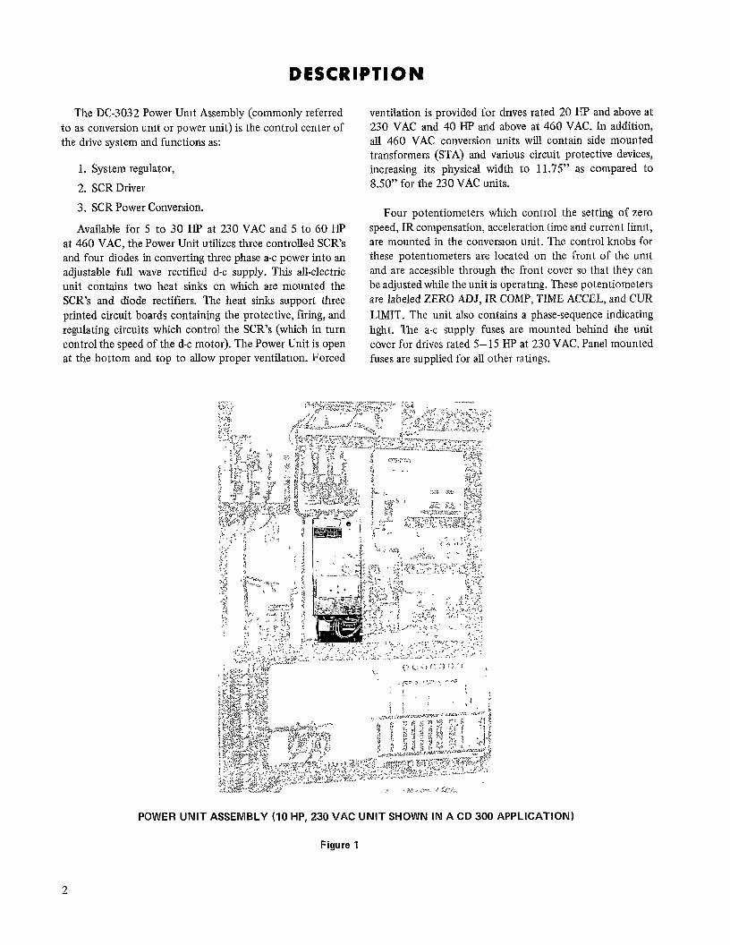
The DC-3032 Power Unit Assembly (commonly referred to as conversion unit or power unit) is the control center of the drive system and functions as:
1. System regulator,
2. SCR Driver
3. SCR Power Conversion.
Available for 5 to 30 HP at 230 VAC and 5 to 60 HP at 460 VAC, the Power Unit utilizes three controlled SCR’s and four diodes in converting three phase a-c power into an adjustable full wave rectified d-c supply. This all-electric unit contains two heat sinks on which are mounted the SCR’s and diode rectifiers. The heat sinks support three printed circuit boards containing the protective, firing, and regulating circuits which control the SCR’s (which in turn control the speed of the d-c motor). The Power Unit is open at the bottom and top to allow proper ventilatron. Forced
ventilation is provided for drives rated 20 HP and above at 230 VAC and 40 HP and above at 460 VAC. In addition, all 460 VAC conversion units will contain side mounted transformers (STA) and various circuit protective devices, increasing its physical width to 11.75” as compared to 8.50” for the 230 VAC units.
Four potentiometers which control the setting of zero speed, IR compensation, acceleration time and current limrt, are mounted in the conversron unit. The control knobs for these potentiometers are located on the front of the unit and are accessible through the front cover so that they can be adjusted while the unit is operatmg. These potentiometers are labeled ZERO ADJ, IR COMP, TIME ACCEL, and CUR LIMIT. The unit also contains a phase-sequence indicating light. The a-c supply fuses are mounted behind the unit cover for drives rated 5-15 HP at 230 VAC. Panel mounted fuses are supplied for all other ratings.
POWER UNIT ASSEMBLY (IO HP, 230 VAC UNIT SHOWN IN A CD 300 APPLICATION)
Figure 1
2
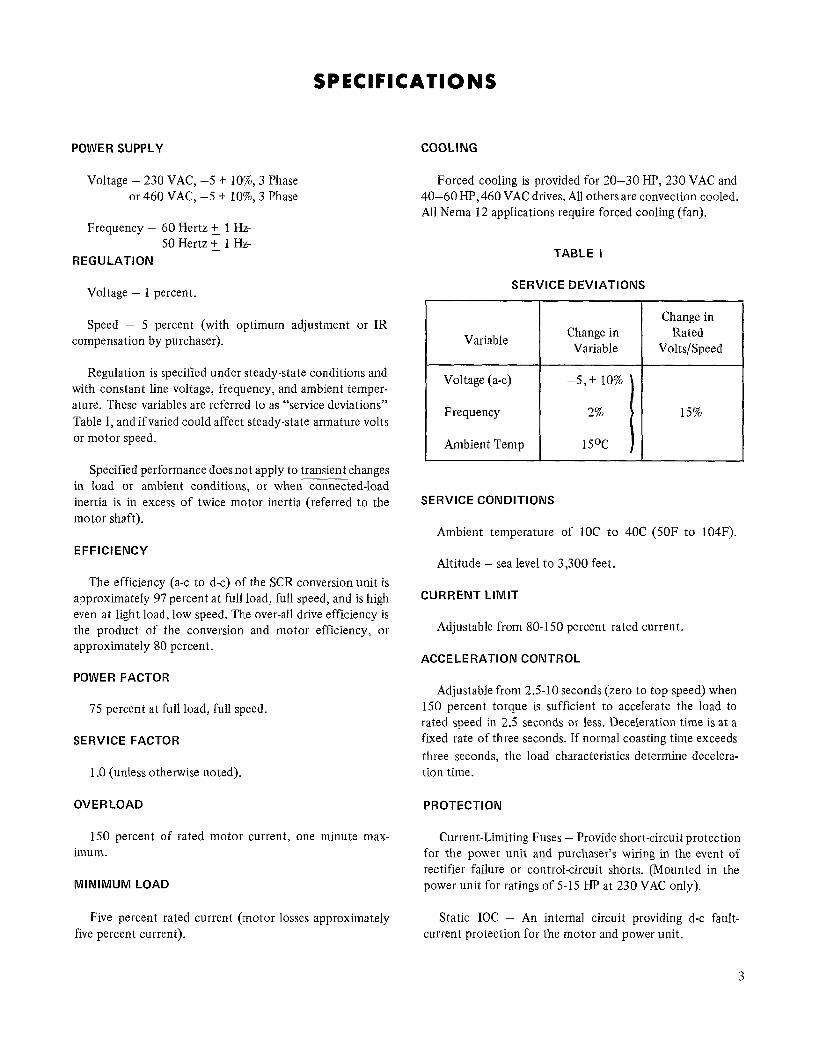
SPECIFICATIONS
POWER SUPPLY COOLING
Voltage - 230 VAC, -5 + lo%, 3 Phase or 460 VAC, -5 + IO%, 3 Phase
Forced cooling is provided for 20-30 HP, 230 VAC and 40-60 HP, 460 VAC drives. All others are convection cooled. All Nema 12 applications require forced cooling (fan).
Frequency - 60 Hertz + 1 Hz 50 Hertz g 1 Hz
REGULATION
Voltage - 1 percent.
Speed - 5 percent (with optimum adjustment or IR compensation by purchaser). Variable
Regulation is specified under steady-state conditions and with constant line voltage, frequency, and ambient temper- ature. These variables are referred to as “service deviations” Table I, and if varied could affect steady-state armature volts or motor speed.
Specified performance does not apply to transient changes in load or ambient conditions, or when connected-load inertia is in excess of twice motor inertia (referred to the motor shaft).
SERVICE CONDITIONS
Ambient temperature of 1OC to 40C (50F to 104F). EFFICIENCY
Altitude - sea level to 3,300 feet. The efficiency (a-c to d-c) of the SCR conversion unit is
approximately 97 percent at full load, full speed, and is high even at light load, low speed. The over-all drive efficiency is the product of the conversion and motor efficiency, or approximately 80 percent.
CURRENT LIMIT
Adjustable from 80-l 50 percent rated current.
ACCELERATION CONTROL
POWER FACTOR
75 percent at full load, full speed.
SERVICE FACTOR
1 .O (unless otherwise noted).
OVERLOAD
Adjustable from 2.5-10 seconds (zero to top speed) when 150 percent torque is sufficient to accelerate the load to rated speed in 2.5 seconds or less. Deceleration time is at a fixed rate of three seconds. If normal coasting time exceeds three seconds, the load characteristics determine decelera- tion time.
PROTECTION
1.50 percent of rated motor current, one minute max- imum.
MINIMUM LOAD
Current-Limiting Fuses - Provide short-circuit protection for the power unit and purchaser’s wiring in the event of rectifier failure or control-circuit shorts. (Mounted in the power unit for ratings of 5-15 HP at 230 VAC only).
Five percent rated current (motor losses approximately five percent current).
Static IOC - An internal circuit providing d-c fault- current protection for the motor and power unit.
TABLE I
SERVICE DEVIATIONS
Change in Variable
Change in Rated
Volts/Speed
15%
3
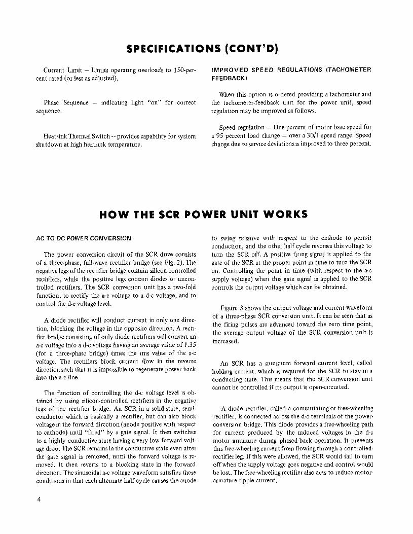
SPECIFICATIONS (CONT’D)
Current Limit - Limits operatmg overloads to 150-per- IMPROVED SPEED REGULATIONS (TACHOMETER cent rated (or less as adjusted). FEEDBACK)
Phase Sequence - indicating light “on” for correct sequence.
When this option 1s ordered providing a tachometer and the tachometer-feedback unit for the power unit, speed regulation may be Improved as follows.
Heatsink Thermal Switch - provides capabillty for system shutdown at high heatsmk temperature.
Speed regulation - One percent of motor base speed for a 95 percent load change - over a 30/l speed range. Speed change due to service deviations 1s improved to three percent.
HOW THE SCR POWER UNIT WORKS
AC TO DC POWER CONVERSION
The power conversion circuit of the SCR drive consists of a three-phase, full-wave rectifier bridge (see Fig. 2). The negative legs of the rectifier bridge contain silicon-controlled rectifiers, wMe the positive legs contam diodes or uncon- trolled rectifiers. The SCR conversion unit has a two-fold function, to rectify the a-c voltage to a d-c voltage, and to control the d-c voltage level.
A diode rectifier will conduct current in only one direc- tion, blocking the voltage in the opposite direction. A rectl- fier bridge consisting of only diode rectifiers will convert an a-c voltage into a d-c voltage having an average value of 1.35 (for a three-phase bridge) times the rms value of the a-c voltage. The rectifiers block current flow in the reverse direction such that It is impossible to regenerate power back into the a-c line.
The function of controlling the d-c voltage level 1s ob- tained by using silicon-controlled rectifiers in the negative legs of the rectifier bridge. An SCR in a solid-state, semi- conductor which 1s basically a rectifier, but can also block voltage m the forward directlon (anode positive with respect to cathode) until “fired” by a gate slgnal. It then switches to a highly conductive state having a very low forward volt- age drop. The SCR remams in the conductive state even after the gate signal is removed, until the forward voltage is re- moved. It then reverts to a blocking state in the forward direction. The sinusoidal a-c voltage waveform satisfies these conditions in that each alternate half cycle causes the anode
4
to swing positive with respect to the cathode to permit conduction, and the other half cycle reverses this voltage to turn the SCR off. A positive flrmg signal is applied to the gate of the SCR at the proper point m time to turn the SCR on. Controlling the pomt in time (with respect to the a-c supply voltage) when this gate signal 1s applied to the SCR controls the output voltage which can be obtained.
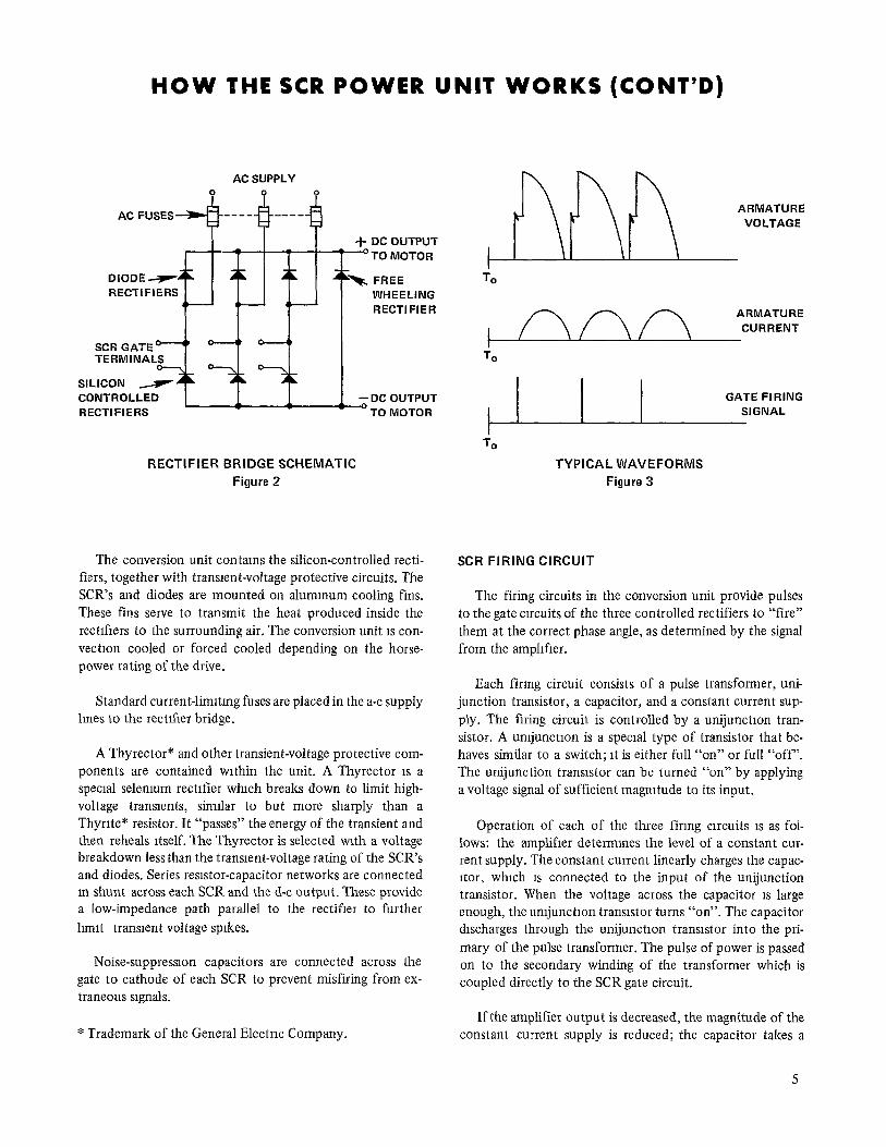
Figure 3 shows the output voltage and current waveform of a three-phase SCR conversion unit. It can be seen that as the firing pulses are advanced toward the zero time point, the average output voltage of the SCR conversion unit is increased.
An SCR has a mmlmum forward current level, called holding current, which 1s required for the SCR to stay m a conducting state. This means that the SCR conversion unit cannot be controlled if its output is open-clrculted.
A diode rectifier, called a commutatmg or free-wheeling rectifier, is connected across the d-c terminals of the power- conversion bridge. This diode provides a free-wheeling path for current produced by the induced voltages in the d-c motor armature during phased-back operation. It prevents this free-wheeling current from flowing through a controlled- rectifier leg. If this were allowed, the SCR would fall to turn off when the supply voltage goes negative and control would be lost. The free-wheeling rectifier also acts to reduce motor- armature ripple current.
HOW THE SCR POWER UNIT WORKS (CONT’D)
AC SUPPLY
AC FUSES+----h----d
I I I -t DC OUTPUT
RECTIFIER BRIDGE SCHEMATIC Figure 2
The conversion unit contams the silicon-controlled recti- fiers, together with transrent-voltage protective circuits. The SCR’s and diodes are mounted on alummum cooling fins. These fins serve to transmit the heat produced inside the rectifiers to the surrounding air. The conversion unit 1s con- vection cooled or forced cooled depending on the horse- power rating of the drive.
Standard current-limrtmg fuses are placed in the a-c supply lines to the rectlfrer bridge.
A Thyrector* and other transient-voltage protective com- ponents are contained wrthin the unit. A Thyrector 1s a special selenium rectrfier whrch breaks down to limit high- voltage transients, similar to but more sharply than a Thyrite* resistor. It “passes” the energy of the transient and then reheals itself. The Thyrector is selected with a voltage breakdown less than the transient-voltage rating of the SCR’s and diodes. Series resistor-capacitor networks are connected in shunt across each SCR and the d-c output. These provide a low-impedance path parallel to the rectifier to further hmrt transient voltage spikes.
Noise-suppression capacitors are connected across the gate to cathode of each SCR to prevent misfiring from ex- traneous signals.
* Trademark of the General Electrrc Company.
To
TYPICAL WAVEFORMS Figure 3
SCR FIRING CIRCUIT
The firing circuits in the conversion unit provide pulses to the gate circuits of the three controlled rectifiers to “fire” them at the correct phase angle, as determined by the signal from the amplifier.
Each firing circuit consists of a pulse transformer, uni- junction transistor, a capacitor, and a constant current sup- ply. The firing circuit is controlled by a unijunctron tran- sistor. A umjunctron is a special type of transistor that be- haves similar to a switch; rt is either full “on” or full “off’. The unijunction transistor can be turned “on” by applying a voltage signal of sufficient magnitude to its input.
Operation of each of the three firing circuits 1s as fol- lows: the amplifier determines the level of a constant cur- rent supply. The constant current linearly charges the capac- itor, whrch 1s connected to the input of the unijunction transistor. When the voltage across the capacitor 1s large enough, the umjunctron transistor turns “on”. The capacitor discharges through the unijunctron transistor into the pri- mary of the pulse transformer. The pulse of power is passed on to the secondary winding of the transformer which is coupled directly to the SCR gate circuit.
If the amplifier output is decreased, the magnitude of the constant current supply is reduced; the capacitor takes a
5
UNIT WORKS (CONT’D)
longer time to charge, and the urujunctron transistor turns on later in the cycle. Hence, the SCR’s fire closer to the end of the cycle and the average d-c output voltage 1s decreased.
The firing circuits are synchronized with the a-c supply such that the firing pulses to the three SCR’s are spaced l/3 cycle apart. The SCR’s wrll remain in the conducting state after the signal is removed, until the anode-to-cathode volt- age is reversed.
MOTOR SHUNT FIELD EXCITATION
Excitation for the motor shunt field may be obtained from a part of the full-wave rectifier bndge used to control the motor armature circuit or an external exciter may be supplied.
The motor shunt field may be connected between one a-c lure and the positive side of the full-wave rectifier bridge. The positive side of this bridge contains three diode rectifiers. Two diode rectifiers furnish two-thuds power to the motor shunt field, while the other diode rectifier acts as a com- mutating or free-wheeling diode. This diode provides a free- wheeling path for the current produced by the induced volt- ages in the motor shunt field. External exciters can either be controlled or uncontrolled voltage.
REFERENCE ERROR SIGNAL
+
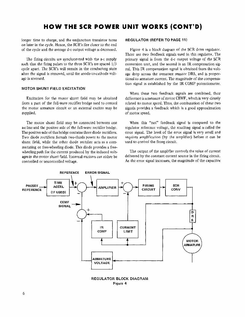
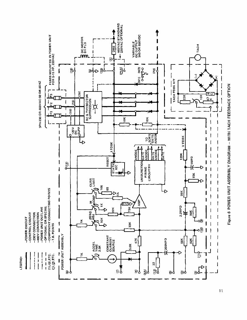
REGULATOR (REFER TO PAGE 11)
Figure 4 is a block diagram of the SCR drive regulator. There are two feedback signals used in this regulator. The primary signal is from the d-c output voltage of the SCR conversion unit, and the second is an IR compensation sig- nal. This IR compensation signal is obtained from the volt- age drop across the armature resistor DRS, and is propor- tional to armature current. The magnitude of the compensa- tion signal 1s established by the IR COMP potentiometer.
When these two feedback srgnals are combined, then drfference is ameasure of motor CEMF, whrch is very closely related to motor speed. Thus, the combmation of these two signals provides a feedback which is a good approximation of motor speed.
When this “net” feedback signal is compared to the regulator reference voltage, the resulting signal 1s called the error signal. The level of the error signal is very small and requires amplification (by the amplifier) before rt can be used to control the firrng circuit.
The output of the amplifier controls the value of current delivered by the constant current source in the firing circuit. As the error signal increases, the magnitude of the capacitor
r CURRENT LIMIT
J I
REGULATOR BLOCK DIAGRAM Figure 4
HOW THE SCR POWER UNIT WORKS (CONT’D)
constant charging current increases. With a rapid charging rate, the capacitor is charged quickly and the firing pulse occurs early in the cycle. This results in turning the SCRs “on” at an earlier point in the a-c wave, increasing the average d-c output voltage.
TIMED ACCELERATION
The timed acceleration function is inserted between the preset reference voltage and the regulator references as shown in Figure 4. It consists essentially of a constant current source and a capacitor. When this current source is used to charge the capacitor, its voltage will increase approximately linearly wrth time at a rate (2.5 to 10 seconds) set by the TIME ACCEL potentiometer.
Whenever the preset reference is at a higher value than the regulator reference, the timing circuit becomes operative. If the value of preset reference is reduced below the regulator reference voltage the capacitor in the TIME ACCEL ckult wrll dtscharge at a fixed exponential rate, reducing the regulator reference voltage.
Under these conditions, the drive will decelerate to the new preset speed at this rate, assummg that this rate is slower than the normal coasting time of the drive and its con- nected load.
For a “drive stop” command, the capacitor may be dis- charged by shorting terminal board points 5 and 12 in that condition.
CURRENT LIMIT
The current limit signal is obtained from the voltage across a dropping resrstor (DRS) located m the armature loop, external to the power unit assembly. This voltage is propor- tiOd t0 the motor armature current. The magnitude of the
current limit feedback signal is adjusted by the “CUR LIMIT” potentiometer.
When the armature current feedback signal increases to the limit setting, it acts to retard the charging rate of the capacitor in the firing circuit. The unijunction transistor fires later and the SCR’s are phased back (turn on later in the cycle) until the armature current is reduced to the level determined by the setting of the CUR LIMIT potentiometer.
STATIC IOC CIRCUIT
A static instantaneous-overcurrent circuit senses armatrue current. When current exceeds approximately 300 percent, this circuit prevents the SCR’s from frrmg and so reduces output voltage to zero in l/3 cycle.
The circuit is reset by momentarily connecting terminal board points 13 and 5 on 2TB (see page 11).
TACHOMETER FEEDBACK
The tachometer generator provides a voltage-feedback signal proportional to motor speed. This voltage-feedback signal 1s fed into a full-wave rectifier bridge which makes the feedback signal msensrtive to the polarity of the tachom- eter-generator output voltage. A resistor bridge, located immediately after the full-wave rectifier bridge, reduces the tachometer-generator output voltage to a suitable value. The output of the resistor bridge is then fed to points 1 and 5 on the power unit terminal board 2TB.
The armature-voltage feedback is disconnected by re- movmg the jumper between termmal board points 9 and 10 on 2TB thus permitting the tachometer generator to control the drive. Since the tachometer generator provides an accurate speed signal, the IR camp circuit is not required and “IR COMP” is set to zero (CCW).
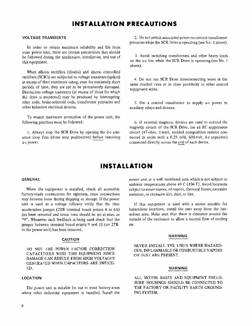
VOLTAGE TRANSIENTS
In order to obtain maximum reliability and life from your power unit, there are certain precautions that should be followed during the applicatron, installation, and use of this equipment.
When silicon rectifiers (diodes) and silicon controlled rectifiers (SCR’s) are subjected to voltage transients (spikes) in excess of then maximum rating, even for extremely short periods of time, they are apt to be permanently damaged. Destructive voltage transients (in excess of those for which the drive IS protected) may be produced by interrupting relay coils, brake-solenoid co&,, transformer primaries and other inductive electrical devices.
To ensure maximum protection of the power unit, the following practices must be followed:
1. Always stop the SCR Drive by opening the d-c arm- ature loop first (drive stop pushbutton) before removing a-c power.
INSTAl.l.ATlON PRECAUTIONS
2. Do not switch associated power on control-transformer primaries whrle the SCR Drive is operating (see No. 1 above).
3. Avoid switching transformers and other heavy loads on the a-c line while the SCR Drive is operating (see No. 1 above).
4. Do not run SCR Drive interconnecting wires in the same conduit runs or in close proximity to other control equipment wires.
5. Use a control transformer to supply a-c power to auxrliary relays and devices.
6. If external magnetic devices are used to control the magnetic circuit of the SCR Drive, use an RC suppression circuit (47-ohm, 2-watt, molded composition resistor con- nected in series with a 0.25 mfd, 600~volt, d-c capacitor) connected directly across the coil of each device.
INSTALLATION
GENERAL
When the equipment is installed, check all accessible factory-made connections for tightness, since connections may become loose during shipping or storage. If the power unit 1s used as a voltage follower verify that the time acceleration jumper (2TB terminal board points 4 to 4A) has been removed and linear tune should be set at max. or “9”. Whenever tach feedback 1s being used check that the jumper between terminal board points 9 and 10 (on 2TB in the power unit) has been removed.
CAUTION
DO NOT USE POWER FACTOR CORRECTION CAPACITORS WITH THIS EQUIPMENT SINCE DAMAGE CAN RESULT FROM HIGH VOLTAGES GENERATED WHEN CAPACITORS ARE SWITCH- ED.
LOCATION
The power unit is suitable for use in most factory areas where other industrial equipment is installed. Install the
8
power unit m a well ventrlated area which is not subject to ambient temperatures above 40 C (104 F). Avoid locations subject to steam vapors, oil vapors, chemical fumes, excessive moisture, or excessive dirt, dust, or lint.
If this equipment 1s used with a motor suitable for hazaradous locations, install the unit away from the haz- ardous area. Make sure that there is clearance around the outside of the enclosure to allow a normal flow of cooling air.
WARNING
NEVER INSTALL THE UNITS WHERE HAZARD- OUS, INFLAMMABLE OR COMBUSTIBLE VAPORS OR DUST ARE PRESENT.
WARNING
ALL MOTOR BASES AND EQUIPMENT ENCLO- SURE HOUSINGS SHOULD BE CONNECTED TO THE FACTORY OR FACILITY EARTH GROUND- ING SYSTEM.
/ 0’ Bl
/ /
0 B
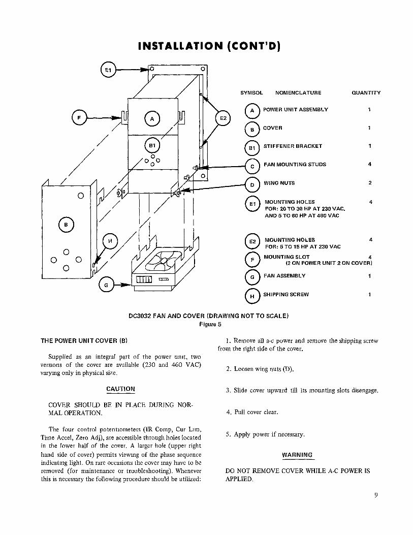
INSTALLATION (CONT’D)
0
SYMBOL NOMENCLATURE
0 A POWER UNIT ASSEMBLY
0 B COVER
0 STIFFENER BRACKET 61
II FAN MOUNTING STUDS
WING NUTS
0 El MOUNTING HOLES FOR: 20 TO 30 HP AT 230 VAC. AND 5 TO 60 HP AT 460 VAC
THE POWER UNIT COVER (6)
0 E2 MOUNTING HOLES
FOR: 5 TO 15 HP AT 230 VAC
0 F MOUNTING SLOT
(2 ON POWER UNIT 2 ON COVER) 0 G FAN ASSEMBLY 1
n H SHIPPING SCREW 1
DC3032 FAN AND COVER (DRAWING NOT TO SCALE) Figure 5
Supplied as an integral part of the power umt, two versrons of the cover are available (230 and 460 VAC) varymg only in physical size.
CAUTION 3. Slide cover upward till its mounting slots disengage.
COVER SHOULD BE IN PLACE DURING NOR- MAL OPERATION.
The four control potentiometers (IR Comp, Cur Lrm, Time Accel, Zero Adj), are accessible through holes located in the lower half of the cover. A larger hole (upper right hand side of cover) permits viewmg of the phase sequence indicatmg light. On rare occasions the cover may have to be removed (for maintenance or troubleshooting). Whenever this is necessary the following procedure should be utilized:
QUANTITY
1. Remove all a-c power and remove the shipping screw from the right side of the cover.
2. Loosen wing nuts (D).
4. Pull cover clear.
5. Apply power if necessary.
WARNING
DO NOT REMOVE COVER WHILE A-C POWER IS APPLIED.
9
INSTALLATION (CONT’D)
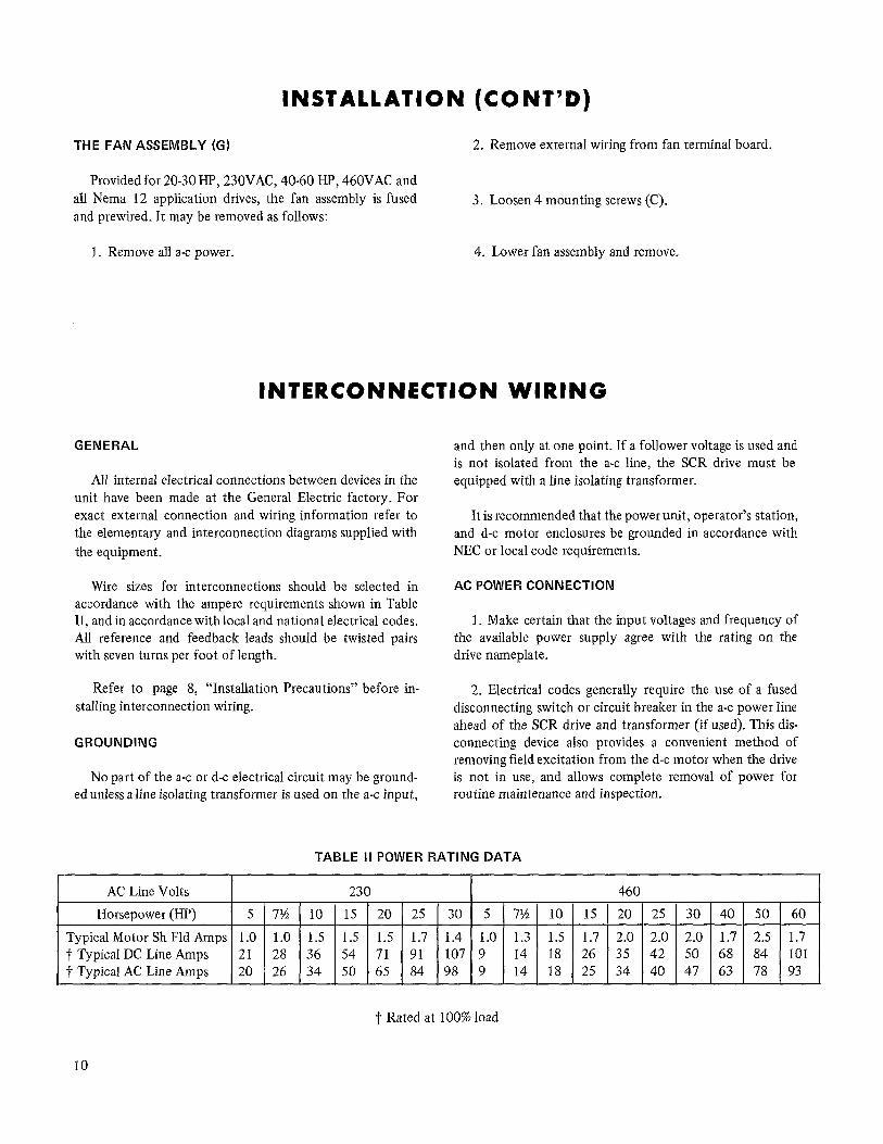
THE FAN ASSEMBLY (G) 2. Remove external wiring from fan terminal board.
Provided for 20-30 HP, 230VAC, 40-60 HP, 460VAC and all Nema 12 application drives, the fan assembly is fused and prewired. It may be removed as follows:
3. Loosen 4 mounting screws (C).
1. Remove all a-c power. 4. Lower fan assembly and remove.
INTERCONNECTION WIRING
GENERAL
All internal electrical connections between devices in the unit have been made at the General Electric factory. For exact external connection and wiring information refer to the elementary and interconnection diagrams supplied with the equipment.
Wire sizes for interconnections should be selected in accordance with the ampere requirements shown in Table II, and in accordance withlocal and national electrical codes. All reference and feedback leads should be twisted pairs with seven turns per foot of length.
Refer to page 8, “Installation Precautions” before in- stalling interconnection wiring.
GROUNDING
No part of the a.-c or d-c electrical circuit may be ground- ed unless aline isolating transformer is used on the a-c input,
and then only at one point. If a follower voltage is used and is not isolated from the a-c line, the SCR drive must be equipped with a line isolating transformer.
It is recommended that the power unit, operator’s station, and d-c motor enclosures be grounded in accordance with NEC or local code requirements.
AC POWER CONNECTION
1. Make certain that the input voltages and frequency of the available power supply agree with the rating on the drive nameplate.
2. Electrical codes generally require the use of a fused disconnecting switch or circuit breaker in the a-c power line ahead of the SCR drive and transformer (if used). This dis- connecting device also provides a convenient method of removing field excitation from the d-c motor when the drive is not in use, and allows complete removal of power for routine maintenance and inspection.
TABLE II POWER RATING DATA
AC Line Volts 230 1 460
Horsepower (HP) 5 7% 10 15 20 25 30 5 7Y i 1 10 [ 15 ( 20 1 25 ( 30 ( 40 1 50 1 60
TypicalMotor Sh Fld Amps 1.0 1.0 1.5 1.5 1.5 1.7 1.4 1.0 t Typical DC Line Amps 21 28 36 54 71 91 107’9 14’18
1.3 1.5 1.7 2.0 2.0 2.0 1.7 2.5 1.7
t Typical AC Line Amps 20 26 34 50 65 84 98 9 14 18 26j-&K?~~ 25
t Rated at 100% load
10
LEG
END:
-POW
ER
CIRC
UIT
-CON
TROL
CI
RCUI
T ---
a -
-23O
V CO
NNEC
TION
e-
e -4
60V
CONN
ECTI
ON
--a-
-POW
ER
UNIT
OU
TLIN
E 3P
H-23
0 OR
46
0VAC
-60
OR
60HZ
A
----
-O
PTIO
NAL
OR
SPEC
IAL
~),~
,ETc
. -C
OMPO
NENT
CO
NNEC
TING
PO
INTS
FU
SES
MOU
NTED
IN
PO
WER
UN
IT
l$,lz
),ETC
. -T
.B.
POIN
TS
FOR
5-15
HP
, 23
0VAC
I ---
--P---
--P--
POW
ER
UNIT
AS
SEM
BLY
I, (tj
) I I I I I I I I I I I I I
-1
(1_9
) 0
- (1
6)
+2ov
DC
--
= -+
I
DC
MOT
OR
RC
&?I TH
Y RE
CTOR
sk
i FL
D E,
l”O
~Ef~
,o(,,
T I D L,
r IO
K
-’ -’
-’
A CO
NSTA
NT
1 ”
1,
” 11
168
I RE
SETI
460V
AC
STAN
DARD
23
0VAC
OP
TION
AL
I VA
RIAB
LE
DC
OUTP
UT
WI)
(W2)
24
0 OR
50
0VDC
VI
” &g
CIRC
UITR
Y I?
(P2)
c -
---+
200M
FD
IAN~
DE
I ANO
DE
I I i ---
-- I I ’ r
r TAcHFO
BKT-
1
TACH
Figu
re
6 PO
WER
UN
IT
ASSE
MBL
Y DI
AGRA
M
-WIT
H TA
CH
FEED
BACK
OP
TION

PHASE SEQUENCE INDICATING LIGHT
(“ON” FOR IN-PHASE POWER)
CONTROL ADJUSTMENTS
FTB
(2) FUSE
I-u OADJ lRCoMpCUR‘,M
TIME ACCEL FAN
FAN FUSE (FFU)
FAN TERMINAL BOARD (FTB)
Figure 7 DC3032 POWER UNIT ASSEMBLY WITH FAN (460 VAC, 60 HP UNlT SHOWN)
Figure 8 POWER UNIT ASSEMBLY WITH COVER (230VAC, 15HP Unit Shown)
NOTE
Figure 9 POWER UNIT ASSEMBLY WITH COVER AND STIFFENER BRACKET REMOVED
(230VAC, 15HP Unit Shown)
THE MAIN AC LINE FUSES ARE MOUNTED ON THE CONVERSION UNIT FOR 230 VAC, S-15 HP DRIVES, AND PANEL MOUNTED FOR ALL OTHER RATINGS.
12
SETUP AND ADJUSTMENT FOR THE POWER UNIT ASSEMBLY IN A DRIVE
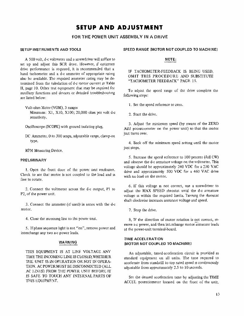
SETUP INSTRUMENTS AND TOOLS
A 500 volt, d-c voltmeter and a screwdriver will suffice to set up and adjust this SCR drwe. However, rf optimum drive performance is required, it is recommended that a hand tachometer and a d-c ammeter of appropriate rating also be available. The required ammeter rating may be de- termined from the tabulation of d-c motor current in Table II, page 10. Other test equipment that may be required for auxiliary functions and devices or detarled troubleshootmg are listed below:
Volt-ohm Meter (VOM), 3 ranges Mimmum: Xl, X10, X100; 20,000 ohm per volt d-c sensitivity.
Oscilloscope (SCOPE) with ground isolating plug.
DC Ammeter, 0 to 300 amps, adJustable range, clamp-on type.
RPM Measuring Device.
PRELIMINARY
1. Open the front door of the power unit enclosure. Check to see that motor is not coupled to the load and 1s free to rotate,
2. Connect the voltmeter across the d-c output, Pl to P2, of the power unit.
3. Connect the ammeter (rf used) in series with the d-c motor.
4. Close the mcornmg line to the power unit.
5. Ifphase sequence lrght is not “on”, remove power and interchange any two a-c power leads.
WARNING
THIS EQUIPMENT IS AT LINE VOLTAGE ANY TIME THE INCOMING LINE IS CLOSED, WHETHER THE UNIT IS IN OPERATION OR NOT IN OPERA- TION. AC POWER MUST BE DISCONNECTED (ALL AC LINES) FROM THE POWER UNIT BEFORE IT IS SAFE TO TOUCH ANY INTERNAL PARTS OF THIS EQUIPMENT.
SPEED RANGE (MOTOR NOT COUPLED TO MACHINE)
NOTE:
IF TACHOMETER-FEEDBACK IS BEING USED, OMIT THIS PROCEDURE AND SUBSTITUTE “TACHOMETER FEEDBACK” PAGE 15.
To adjust the speed range of the drive complete the following steps:
1. Set the speed reference to zero.
2. Start the drive.
3. Adjust the minimum speed (by means of the ZERO ADJ potentiometer on the power unit) so that the motor just turns over.
4. Back off the minimum speed setting until the motor just stops.
5. Increase the speed reference to 100 percent (full CW) and observe the d-c armature voltage on the voltmeter. This voltage should be approximately 240 VDC for a 230 VAC drive and approximately 500 VDC for a 460 VAC drive with no load on the motor.
6. If this voltage IS not correct, use a screwdriver to adjust the MAX SPEED rheostat untrl the d-c armature voltage 1s within the required hmits. Turning the rheostat shaft clockwise increases armature voltage and speed.
7. Stop the drive.
8. If the direction of motor rotation is not correct, re- move a-c power, and then interchange motorarmature leads at the power-unit terminal-board.
TIME ACCELERATION (MOTOR NOT COUPLED TO MACHINE)
An adjustable, timed-acceleration circuit is provided as standard equipment on all units. The trme required to accelerate from standstill to top rated speed 1s continuously adJustable from approximately 2.5 to 10 seconds.
Set the desired acceleration time by adjusting the TIME ACCEL potentiometer located on the front of the unit.
13
SETUP AND ADJUSTMENT (CONT’D) FOR THE POWER UNIT ASSEMBLY IN A DRIVE
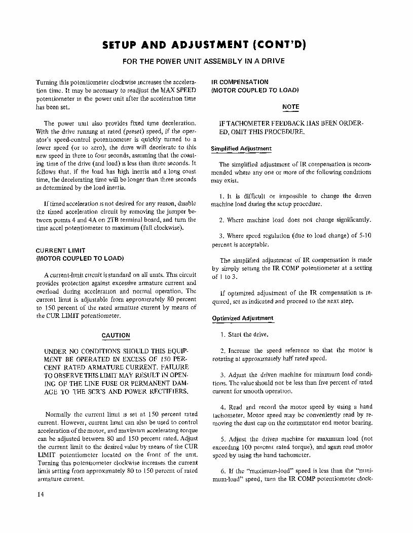
Turning this potentiometer clockwise increases the accelera- tion time. It may be necessary to readjust the MAX SPEED potentiometer m the power unit after the acceleration time has been set.
The power umt also provides fiied tnne deceleration. With the drive runnmg at rated (preset) speed, if the oper- ator’s speed-control potentiometer is quickly turned to a lower speed (or to zero), the drive will decelerate to this new speed in three to four seconds, assuming that the coast- ing time of the drive (and load) 1s less than three seconds. It follows that, if the load has high inertia and a long coast time, the decelerating time will be longer than three seconds as determined by the load inertia.
If timed acceleration IS not desired for any reason, drsable the timed acceleration circuit by removing the jumper be- tween points 4 and 4A on 2TB terminal board, and turn the time accel potentiometer to maximum (full clockwise).
CURRENT LIMIT (MOTOR COUPLED TO LOAD)
A current-hmit crrcuit is standard on all umts. This circuit provides protection against excessive armature current and overload during acceleration and normal operation. The current limit is adjustable from approxnnately 80 percent to 150 percent of the rated armature current by means of the CUR LIMIT potentiometer.
CAUTION
UNDER NO CONDITIONS SHOULD THIS EQUIP- MENT BE OPERATED IN EXCESS OF 150 PER- CENT RATED ARMATURE CURRENT. FAILURE TO OBSERVE THIS LIMIT MAY RESULT IN OPEN- ING OF THE LINE FUSE OR PERMANENT DAM- AGE TO THE SCR’S AND POWER RECTIFIERS.
Normally the current limit 1s set at 150 percent rated current. However, current limit can also be used to control acceleration of the motor, and maximum acceleratmg torque can be adjusted between 80 and 150 percent rated. Adjust the current limit to the desired value by means of the CUR LIMIT potentiometer located on the front of the umt. Turning ths potentiometer clockwise increases the current limit setting from approxunately 80 to 150 percent of rated armature current.
14
IR COMPENSATION (MOTOR COUPLED TO LOAD)
NOTE
IF TACHOMETER FEEDBACK HAS BEEN ORDER- ED, OMIT THIS PROCEDURE.
Simplified Adjustment
The simplified adjustment of IR compensation is recom- mended where any one or more of the following conditions may exist.
1. It is difficult or impossible to change the driven machine load during the setup procedure.
2. Where machine load does not change significantly.
3. Where speed regulation (due to load change) of 5-10 percent is acceptable.
The simplified adjustment of IR compensation is made by simply setting the IR COMP potentiometer at a setting of 1 to3.
If optnnized adjustment of the IR compensation 1s re- quired, set as indicated and proceed to the next step.
Optimized Adjustment
1. Start the drive.
2. Increase the speed reference so that the motor is rotating at approxunately half rated speed.
3. Adjust the driven machine for mimmum load condi- tions. The value should not be less than five percent of rated current for smooth operation.
4. Read and record the motor speed by using a hand tachometer. Motor speed may be conveniently read by re- moving the dust cap on the commutator end motor bearing.
5. Adjust the driven machine for maxlmum load (not exceeding 100 percent rated torque), and again read motor speed by using the hand tachometer.
6. If the “maximum-load” speed is less than the “mmi- mum-load” speed, turn the IR COMP potentiometer clock-

SETUP AND ADJUSTMENT (CONf’D) FOR THE POWER UNIT ASSEh’iBLY IN A DRIVE
wise until they are equal.
7. Repeat Steps 3,4,5 and 6.
8. Increase the speed reference to 100% and readjust the MAX SPEED potentiometer so that the motor is running at the maxnnum speed required for the applicatron, but not in excess of the rated speed on the motor nameplate.
TACHOMETER FEEDBACK (MOTOR NOT COUPLED TO LOAD)
NOTE
FOLLOW THIS PROCEDURE ONLY IF TACHO- METER FEEDBACK HAS BEEN ORDERED.
WARNING
EXCESSIVE SPEED CAN CAUSE DAMAGE TO MOTORS AND SERIOUS INJURY TO PERSON- NEL.
BEFORE ATTEMPTING TO OPERATE THE DRIVE.
1. VERIFY THAT THE TACHOMETER WIRING IS CONNECTED WITH PROPER POLARITY BEING FED BACK TO THE DRIVE.
2. THE MOTOR FIELD SHOULD BE CHECKED TO MAKE SURE IT IS CONNECTED, AT THE MOTOR AND AT THE DRIVE.
3. ANY OVERSPEED OR FIELD-LOSS PROTEC- TION, WHEN PROVIDED, SHOULD BE CONNECT- ED.
1. Turn the IR COMP potentiometer on the front of the unit to the extreme counter-clockwise position (ZERO).
2. Turn the MAX SPEED rheostat clockwise to the mid- point of its travel.
3. Turn the TACH FEEDBACK potentiometer on the tachometer-feedback unit to the extreme counter-clockwise position.
4. Set the speed reference to zero.
5. Start the drive.
6. Adjust the ZERO ADJ potentiometer (located on the unit) so that the motor begins to rotate; then, “back off the adjustment until the motor just turns over.
7. Turn the speed reference to 100 percent speed.
8. Turn the TACH FEEDBACK potentiometer clockwise until the drive is running at the maximum speed required for the application. Drive speed may be measured directly by using a hand tachometer, or the voltmeter may be connected across the tach voltage feedback signal to obtain an indrca- tion of speed.
9. Stop the drive.
Proceed with the setup procedure on timed acceleration and current limit shown on Page 13 & 14. IR compensation procedure is not required since the IR COMP signal is not used with tachometer feedback. Make certain that the IR camp pot is turned fully CCW.
FOLLOWER DRIVES
NOTE
FOLLOW THIS PROCEDURE ONLY IF THE DRIVE IS TO BE USED AS A FOLLOWER (FOLLOWING AN EXTERNAL VOLTAGE SIGNAL).
1. Remove metal jumper from points 4 to 4A on 2TB terminal board.
2. Follow the setup and adjustment procedure previously specified for either voltage-regulated or tachometer-feedback drives, as appropriate.
3. Tracking Adjustment.
If the drive 1s to closely follow the signal voltage, the following adjustments must be made for trackmg.
a. Apply zero speed reference and set the speed tracking pot to the 50% mark.
b. Start the drive.
15
SETUP AND ADJUSTMENT (CONT’D)
FOR THE POWER UNIT ASSEMBLY IN A DRIVE
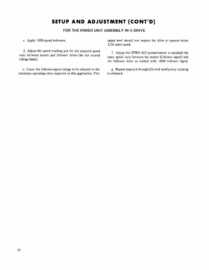
c. Apply 100% speed reference. signal level should not require the drive to operate below l/20 rated speed?
d. Adjust the speed tracking pot for the required speed ratio between master and follower drives (do not exceed voltage limit).
f. Adjust the ZERO ADJ potentiometer to establish the same speed ratio between the master (follower signal) and the follower drive as existed with 100% follower signal.
e. Cause the follower-signal voltage to be reduced to the g. Repeat steps (c) through (f,) until satisfactory tracking minimum operating value expected on this application. This is obtained.
16
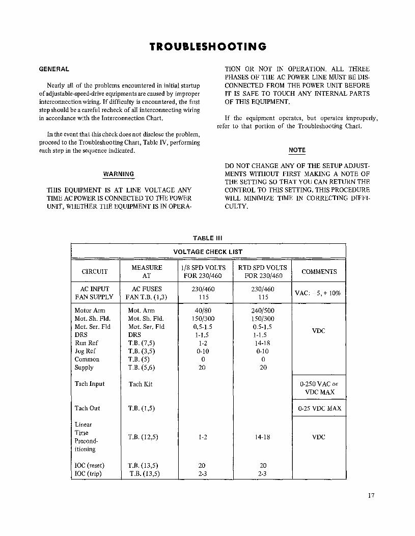
GENERAL
Nearly all of the problems encountered in initial startup of adjustable-speed-drive equipments are caused by improper interconnection wiring. If difficulty is encountered, the first step should be a careful recheck of all interconnecting wiring in accordance with the Interconnection Chart.
In the event that this check does not disclose the problem, proceed to the Troubleshooting Chart, Table IV, performing each step in the sequence indicated.
WARNING
THIS EQUIPMENT IS AT LINE VOLTAGE ANY TIME AC POWER IS CONNECTED TO THE POWER UNIT, WHETHER THE EQUIPMENT IS IN OPERA-
TABLE III
TION OR NOT IN OPERATION. ALL THREE PHASES OF THE AC POWER LINE MUST BE DIS- CONNECTED FROM THE POWER UNIT BEFORE IT IS SAFE TO TOUCH ANY INTERNAL PARTS OF THIS EQUIPMENT.
If the equipment operates, but operates improperly, refer to that portion of the Troubleshooting Chart.
NOTE
DO NOT CHANGE ANY OF THE SETUP ADJUST- MENTS WITHOUT FIRST MAKING A NOTE OF THE SETTING SO THAT YOU CAN RETURN THE CONTROL TO THIS SETTING. THIS PROCEDURE WILL MINIMIZE TIME IN CORRECTING DIFFI- CULTY.
CIRCUIT
AC INPUT FAN SUPPLY
Motor Arm Mot. Sh. Fld. Mot. Ser. Fld DRS Run Ref Jog Ref Common SUPPlY
Tach Input
Tach Out
Linear Time Precond- itioning
IOC (reset) IOC (trip)
VOLTAGE CHECK LIST
MEASURE AT
AC FUSES FAN T.B. (1,3)
Mot. Arm 40180 2401500 Mot. Sh. Fld. 150/300 150/300 Mot. Ser. Fld 0.5-1.5 o-5-1.5 DRS l-l.5 l-l.5 T.B. (7,5) 1-2 14-18 T.B. (3,5) O-10 O-10 T.B. (5) 0 0 T.B. ($6) 20 20
Tach Kit
T.B. (1,5)
T.B. (12,5)
T.B. (13,5) 20 20 T.B. (13,5) 2-3 2-3
l/X SPD VOLTS FOR 230/460
23 O/460 2301460 115 115
1-2
RTD SPD VOLTS FOR 230/460
14-18
COMMENTS
VAC: -5, + 10%
VDC
O-250 VAC or VDC MAX
O-25 VDC MAX
VDC
1
17
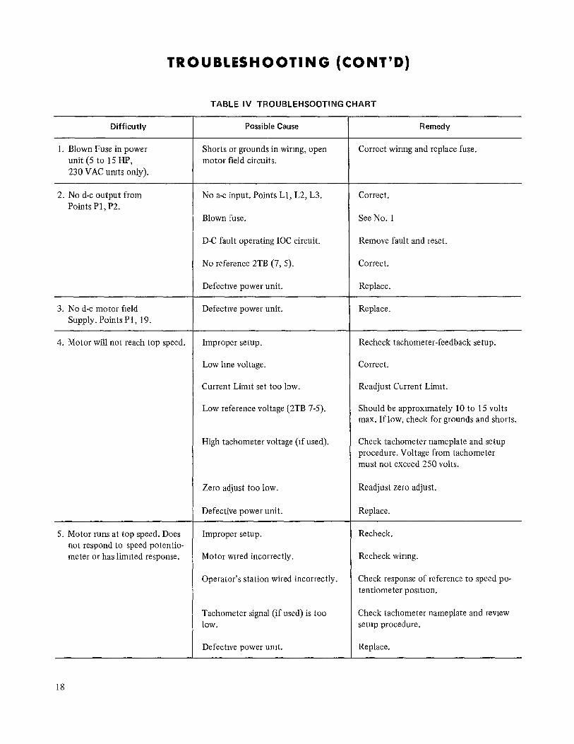
TROUBLESHOOTING (CONT’D)
TABLE IV TROUBLEHSOOTING CHART
Difficutly Possible Cause
1. Blown Fuse in power unit(5to 15HP, 230 VAC umts only).
Shorts or grounds in wiring, open motor field circuits.
2. No d-c output from Points Pl) P2.
No a-c input. Points Ll, L2, L3.
Blown fuse.
D-C fault operating IOC circuit.
No reference 2TB (7, 5).
Defective power unit.
Defective power unit. 3. No d-c motor field Supply. Points Pl, 19.
4. Motor will not reach top speed. Improper setup.
5. Motor runs at top speed. Does Improper setup. not respond to speed potentio- meter or has limited response.
Low line voltage.
Current Limit set too low.
Low reference voltage (2TB 7-5).
High tachometer voltage (if used).
Zero adjust too low.
Defective power unit.
Motor wrred incorrectly.
Operator’s station wired incorrectly. Check response of reference to speed po- tentiometer position.
Tachometer signal (if used) is too Check tachometer nameplate and review low. setup procedure.
Defective power unit. Replace.
Remedy
Correct wiring and replace fuse.
Correct.
See No. 1
Remove fault and reset.
Correct.
Replace.
Replace.
Recheck tachometer-feedback setup.
Correct.
Readjust Current Limit.
Should be approximately 10 to 15 volts max. If low, check for grounds and shorts.
Check tachometer nameplate and setup procedure. Voltage from tachometer must not exceed 250 volts.
Readjust zero adjust.
Replace.
Recheck.
Recheck wiring.
18
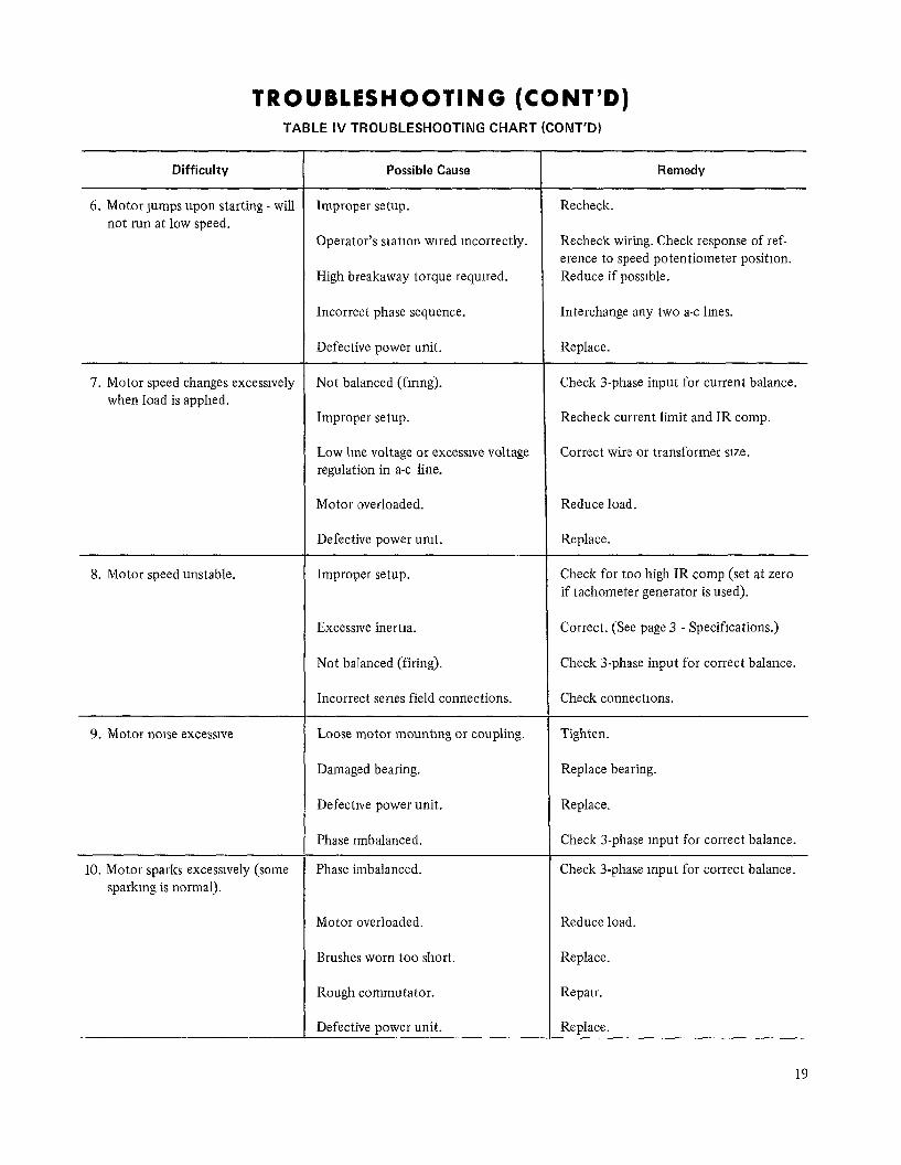
TROUBLESHOOTING (CONT’D) TABLE IV TROUBLESHOOTING CHART (CONT’D)
Difficulty
6. Motor lumps upon starting - will not run at low speed.
7. Motor speed changes excessrvely when load is applied.
8. Motor speed unstable.
9. Motor noise excessive
10. Motor sparks excessively (some sparking is normal).
Possible Cause
Improper setup.
Operator’s statron wired mcorrectly.
High breakaway torque required.
Incorrect phase sequence.
Defective power unit.
Not balanced (fmng).
Improper setup.
Low lme voltage or excessive voltage regulation in a-c line.
Motor overloaded.
Defective power unit.
Improper setup.
Recheck.
Recheck wiring. Check response of ref- erence to speed potentiometer position. Reduce if possible.
Interchange any two a-c lines.
Replace.
Check 3-phase input for current balance.
Recheck current limit and IR camp.
Correct wire or transformer size.
Reduce load.
Replace.
Excessrve inertia.
Not balanced (firing).
Incorrect series field connections.
Loose motor mounting or coupling.
Damaged bearing.
Defective power unit.
Phase rmbalanced.
Phase imbalanced.
Check for too high IR camp (set at zero if tachometer generator is used).
Correct. (See page 3 - Specifications.)
Check 3-phase input for correct balance.
Check connectrons.
Tighten.
Replace bearing.
Replace.
Check 3-phase input for correct balance.
Check 3-phase input for correct balance.
Motor overloaded. Reduce load.
Brushes worn too short. Replace.
Rough commutator. Repair.
Defective power unit. Replace.
Remedy
19
TROUBLESHOOTING (CONT’D) TABLE IV TROUBLESHOOTING CHART (CONT’D)
Difficulty
11. Motor stops for no apparent reason.
Possible Cause
Sudden extreme overload or inter- mittent d-c fault.
Fuse blowing.
Motor thermal shutdown.
Remedy
Remove cause of overload or fault and reset.
Replace fuse.
Remove cause of overload, let motor cool and restart.
PHASE BALANCE ADJUSTMENT
The balance adjustment of the three firing circuit is performed at the factory and the rheostat shafts are sealed by means of a dab of glue. Normally, no further adjustment is required in the field; however, the following set-up pro- cedure is recommended, should further adjustment be re- quired.
NOTE
THE STIFFENER BRACKET MUST BE REMOVED FOR THIS ADJUSTMENT.
1. Connect the vertical input leads of a cathode-ray oscilloscope (CRO) across the DRS resistor, points Pl (t) and 5 (-), to monitor armature current.* The voltage drop across this resistor is approximately l-volt d-c at rated arm- ature current.
2. Connect the drive to the a-c line.
3. Start the drive.
4. Operate the drive at a high enough speed and load to give a display of the armature current on the CR0 screen.
5. Start adjustment of the two balance rheostats from the CW position, and make small successive adjustments of each (see page 12, Figure 9).
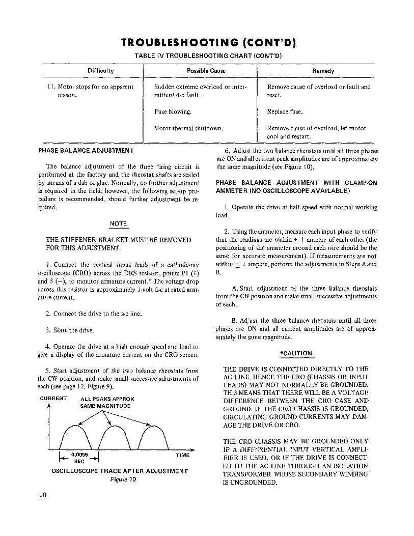
CURRENT ALL PEAKS APPROX
A SAME MAGNITUDE
A 0.0055 TIME SEC
OSCILLOSCOPE TRACE AFTER ADJUSTMENT Figure 10
20
6. Adjust the two balance rheostats until all three phases are ON and all current peak ampIitudes are of approximately the same magnitude (see Figure 10).
PHASE BALANCE ADJUSTMENT WITH CLAMP-ON AMMETER (NO OSCILLOSCOPE AVAILABLE)
1. Operate the drive at half speed with normal working load.
2. Using the ammeter, measure each input phase to verify that the readings are within ‘_ 1 ampere of each other (the positioning of the ammeter around each wire should be the same for accurate measurement). If measurements are not within +_ 1 ampere, perform the adjustments in Steps A and B.
A. Start adjustment of the three balance rheostats from the CW position and make small successive adjustments of each.
B. Adjust the three balance rheostats until all three phases are ON and all current amplitudes are of approx- imately the same magnitude.
*CAUTION
THE DRIVE IS CONNECTED DIRECTLY TO THE AC LINE, HENCE THE CR0 (CHASSIS OR INPUT LEADS) MAY NOT NORMALLY BE GROUNDED. THIS MEANS THAT THERE WILL BE A VOLTAGE DIFFERENCE BETWEEN THE CR0 CASE AND GROUND. IF THE CR0 CHASSIS IS GROUNDED, CIRCULATING GROUND CURRENTS MAY DAM- AGE THE DRIVE OR CRO.
THE CR0 CHASSIS MAY BE GROUNDED ONLY IF A DIFFERENTIAL INPUT VERTICAL AMPLI- FIER IS USED, OR IF THE DRIVE IS CONNECT- ED TO THE AC LINE THROUGH AN ISOLATION TRANSFORMER WHOSE SECONDARY WINDING IS UNGROUNDED.

, General Electric company l Speed Variator Products Department * Erie, Pennsylvania 16501
GEK-11028 l-73 (2500)