Embed Size (px)
DESCRIPTION
Huwaei DBS 3900 Commissioning Guide-(V300R008_04)
Citation preview
DBS3900 GSM
V300R008
Commissioning Guide
Issue 04
Date 2008-09-05
Part Number
Huawei Proprietary and ConfidentialCopyright © Huawei Technologies Co., Ltd
Huawei Technologies Co., Ltd. provides customers with comprehensive technical support and service. For anyassistance, please contact our local office or company headquarters.
Huawei Technologies Co., Ltd.Address: Huawei Industrial Base
Bantian, LonggangShenzhen 518129People's Republic of China
Website: http://www.huawei.com
Email: [email protected]
Copyright © Huawei Technologies Co., Ltd. 2008. All rights reserved.No part of this document may be reproduced or transmitted in any form or by any means without prior writtenconsent of Huawei Technologies Co., Ltd. Trademarks and Permissions
and other Huawei trademarks are the property of Huawei Technologies Co., Ltd.All other trademarks and trade names mentioned in this document are the property of their respective holders. NoticeThe information in this document is subject to change without notice. Every effort has been made in thepreparation of this document to ensure accuracy of the contents, but the statements, information, andrecommendations in this document do not constitute a warranty of any kind, express or implied.
Huawei Proprietary and ConfidentialCopyright © Huawei Technologies Co., Ltd
Contents
About This Document.....................................................................................................................1
1 Safety Information.....................................................................................................................1-11.1 Safety Precautions...........................................................................................................................................1-11.2 Electricity Safety.............................................................................................................................................1-31.3 Inflammable Environment...............................................................................................................................1-51.4 Battery.............................................................................................................................................................1-51.5 Radiation.........................................................................................................................................................1-71.6 Working at Heights.........................................................................................................................................1-91.7 Mechanical Safety.........................................................................................................................................1-111.8 Others............................................................................................................................................................1-12
2 General Requirements for DBS3900 Commissioning........................................................2-12.1 DBS3900 Commissioning Prerequisites.........................................................................................................2-22.2 DBS3900 Commissioning Resources.............................................................................................................2-2
3 DBS3900 Commissioning Procedure......................................................................................3-1
4 Starting the Site Maintenance Terminal System.................................................................4-14.1 Setting the IP Address of the Site Maintenance Terminal PC........................................................................4-24.2 Connecting the Site Maintenance Terminal PC to the BTS............................................................................4-24.3 Locally Logging In to the BTS.......................................................................................................................4-3
5 Running the DBS3900 Software..............................................................................................5-15.1 Obtaining the Site Management Rights..........................................................................................................5-25.2 Checking the Current Software Versions........................................................................................................5-25.3 Forcibly Loading Software..............................................................................................................................5-45.4 Activating Software.........................................................................................................................................5-6
6 Checking the Transmission and Networking......................................................................6-16.1 Checking the Transmission Between the BBU and the RRU.........................................................................6-26.2 Checking the Transmission Between the BBU and the BSC..........................................................................6-36.3 Checking the Consistency Between Actual Networking and Data Configuration..........................................6-4
7 Commission the Antenna System...........................................................................................7-17.1 Measuring the VSWR at the Antenna Port.....................................................................................................7-27.2 Checking the Antenna Connection..................................................................................................................7-2
DBS3900 GSMCommissioning Guide Contents
Issue 04 (2008-09-05) Huawei Proprietary and ConfidentialCopyright © Huawei Technologies Co., Ltd
i
7.2.1 Checking the Antenna Connection with an MS.....................................................................................7-37.2.2 Checking the Antenna Connection by Using a Drive Tester.................................................................7-4
7.3 Measuring the Output Power of the TRX.......................................................................................................7-4
8 Checking the operating status of the DBS3900....................................................................8-18.1 Checking the Status of the DBS3900 LEDs....................................................................................................8-28.2 Checking the Alarm Information of the DBS3900.........................................................................................8-28.3 Performing the Loopback Test........................................................................................................................8-3
9 Testing the DBS3900 Services .................................................................................................9-19.1 Performing the Loopback Test of a Channel...................................................................................................9-2
9.1.1 Performing the Loopback Test of a Signaling Channel.........................................................................9-29.1.2 Performing the Loopback Test of a Traffic Channel.............................................................................9-3
9.2 Testing CS Services........................................................................................................................................9-49.3 Testing PS Services.........................................................................................................................................9-5
10 Monitoring the Environment for the DBS3900................................................................10-110.1 BTS Environment Alarm Types..................................................................................................................10-210.2 Monitoring Environment.............................................................................................................................10-3
11 FAQs for BTS Commissioning............................................................................................11-111.1 Failed Communication Between the Site Maintenance Terminal and the BTS..........................................11-211.2 Faulty E1 Link.............................................................................................................................................11-311.3 Failure of an MS to Search the Network.....................................................................................................11-511.4 Service Dialing Failure................................................................................................................................11-611.5 Low GRPS Data Transmission Rate...........................................................................................................11-6
12 Data Sheet for Commissioning...........................................................................................12-1
ContentsDBS3900 GSM
Commissioning Guide
ii Huawei Proprietary and ConfidentialCopyright © Huawei Technologies Co., Ltd
Issue 04 (2008-09-05)
Figures
Figure 1-1 Wearing an ESD wrist strap...............................................................................................................1-5Figure 1-2 Lifting a weight................................................................................................................................1-10Figure 1-3 Slant angle........................................................................................................................................1-11Figure 1-4 One meter higher than the eave........................................................................................................1-11Figure 4-1 Communication failed dialog box......................................................................................................4-4Figure 4-2 Site Maintenance Terminal System window......................................................................................4-4Figure 4-3 Set Communication Port Parameter dialog box.................................................................................4-5Figure 5-1 Site Management Right dialog box....................................................................................................5-2Figure 5-2 Board Management window...............................................................................................................5-3Figure 5-3 Topology Management window.........................................................................................................5-4Figure 5-4 Board Information dialog box............................................................................................................5-4Figure 5-5 Software Download dialog box..........................................................................................................5-6Figure 5-6 Software Activation dialog box..........................................................................................................5-8Figure 5-7 Software Activation dialog box..........................................................................................................5-8Figure 6-1 Physical loopback of E1/T1 at the DDF.............................................................................................6-4Figure 6-2 Distribution of slots for boards of the BBU.......................................................................................6-5Figure 6-3 RRU module data configuration in the Topology Management window...........................................6-7Figure 6-4 BBU data configuration in the Board Management window.............................................................6-8Figure 8-1 Board Management window...............................................................................................................8-4Figure 8-2 Loop Test dialog box..........................................................................................................................8-4Figure 8-3 Topology Management window.........................................................................................................8-5Figure 9-1 BT Loop Test dialog box....................................................................................................................9-3Figure 9-2 Channel Loop Test dialog box............................................................................................................9-4Figure 10-1 Environment Monitor dialog box...................................................................................................10-4Figure 11-1 Checking the IP address of the board.............................................................................................11-3Figure 11-2 Physical loopback of the E1/T1 cable on the BTS side..................................................................11-4
DBS3900 GSMCommissioning Guide Figures
Issue 04 (2008-09-05) Huawei Proprietary and ConfidentialCopyright © Huawei Technologies Co., Ltd
iii

Tables
Table 2-1 Tools and instruments required for the DBS3900 commissioning......................................................2-2Table 5-1 Parameters available in the Software Download dialog box................................................................5-5Table 5-2 Parameters in the Software Activation dialog box...............................................................................5-7Table 6-1 Mapping between the actual slots and the configured slots.................................................................6-5Table 8-1 Parameters available in the Loopback Test dialog box........................................................................8-3Table 10-1 Parameters in the Environment Monitor dialog box........................................................................10-3Table 11-1 Possible causes and handling suggestions for failed communication between the Site MaintenanceTerminal and the BTS.........................................................................................................................................11-2Table 11-2 Meaning of the states of the LIU LED (UELP used)......................................................................11-4Table 11-3 Meanings of the states of the LIU LED (UELP not used)...............................................................11-5Table 11-4 Possible causes and handling suggestions for service dialing failure..............................................11-6Table 11-5 Description of the DIP switch SW2 on the GTMU.........................................................................11-6Table 12-1 BTS commissioning data sheet........................................................................................................12-1
DBS3900 GSMCommissioning Guide Tables
Issue 04 (2008-09-05) Huawei Proprietary and ConfidentialCopyright © Huawei Technologies Co., Ltd
v

About This Document
PurposeThe DBS3900 GSM Commissioning Guide enables you to commission the DBS3900 GSMproperly so that it functions normally after commissioning and preliminary verification. Thisdocument provides guidelines for commissioning the DBS3900 GSM, which involves thefollowing tasks: starting the Site Maintenance Terminal System, running the DBS3900 GSMsoftware, checking the transmission and networking, commissioning the antenna system,checking the operating status of the DBS3900 GSM, testing the services on the DBS3900 GSM,checking the DBS3900 GSM environment, and typical FAQs for the commissioning.
Product VersionThe following table lists the product version related to this document.
Product Name Product Version
DBS3900 GSM(referred to as DBS3900in this manual)
V300R008
Intended AudienceThis document is intended for:
l Field engineers
l Technical support engineers
Change HistoryFor changes in the document, refer to Changes in DBS3900 GSM Commissioning Guide.
Organization
1 Safety Information
2 General Requirements for DBS3900 Commissioning
The general requirements for DBS3900 commissioning are the commissioning prerequisites andcommissioning resources.
3 DBS3900 Commissioning Procedure
DBS3900 GSMCommissioning Guide About This Document
Issue 04 (2008-09-05) Huawei Proprietary and ConfidentialCopyright © Huawei Technologies Co., Ltd
1
This describes how to commission the DBS3900.
4 Starting the Site Maintenance Terminal System
Before starting the Site Maintenance Terminal, firstly, set the IP address of the Site MaintenanceTerminal PC; secondly, connect the Site Maintenance Terminal PC to the BTS; finally, log into the Site Maintenance Terminal.
5 Running the DBS3900 Software
This describes how to load the correct software version to the boards of the BBU and RRU andhow to activate the board software. To run the DBS3900 software, you should obtain the sitemanagement rights and check the current board software version. If the board software versionis improper, you must load the proper software version and then activate it.
6 Checking the Transmission and Networking
This describes how to check the transmission and networking of the DBS3900. The proceduresinvolve checking whether the transmission between the BBU and the RRU is normal, checkingwhether the transmission between the BBU and the BSC is normal, and checking whether thedata configuration is consistent with the actual networking of the DBS3900.
7 Commission the Antenna System
This describes how to commission the antenna system. You must check whether the antenna isconnected properly and whether the Voltage Standing-Wave Ratio (VSWR) is normal. If anRET antenna is configured, you must commission the RET antenna.
8 Checking the operating status of the DBS3900
This describes how to check the operation status of the DBS3900. To ensure the normal operationof the DBS3900, you need to check its operating status and rectify the faults accordingly. Theprocedure of checking the operation status of the DBS3900 involves checking the status of LEDs,checking the alarm information of the DBS3900, and performing the board loopback test.
9 Testing the DBS3900 Services
This describes how to test the DBS3900 services by using a test MS. The DBS3900 servicesconsist of the circuit switched (CS) services and the packet switched (PS) services.
10 Monitoring the Environment for the DBS3900
This describes the various environment alarms of the DBS3900. It also describes how to performenvironment monitoring for the DBS3900.
11 FAQs for BTS Commissioning
This describes the fault symptoms and cause analysis in the BTS commissioning.
12 Data Sheet for Commissioning
The commissioning data sheet is used to record the process and result of the commissioning.
Conventions
1. Symbol Conventions
The following symbols may be found in this document. They are defined as follows
About This DocumentDBS3900 GSM
Commissioning Guide
2 Huawei Proprietary and ConfidentialCopyright © Huawei Technologies Co., Ltd
Issue 04 (2008-09-05)
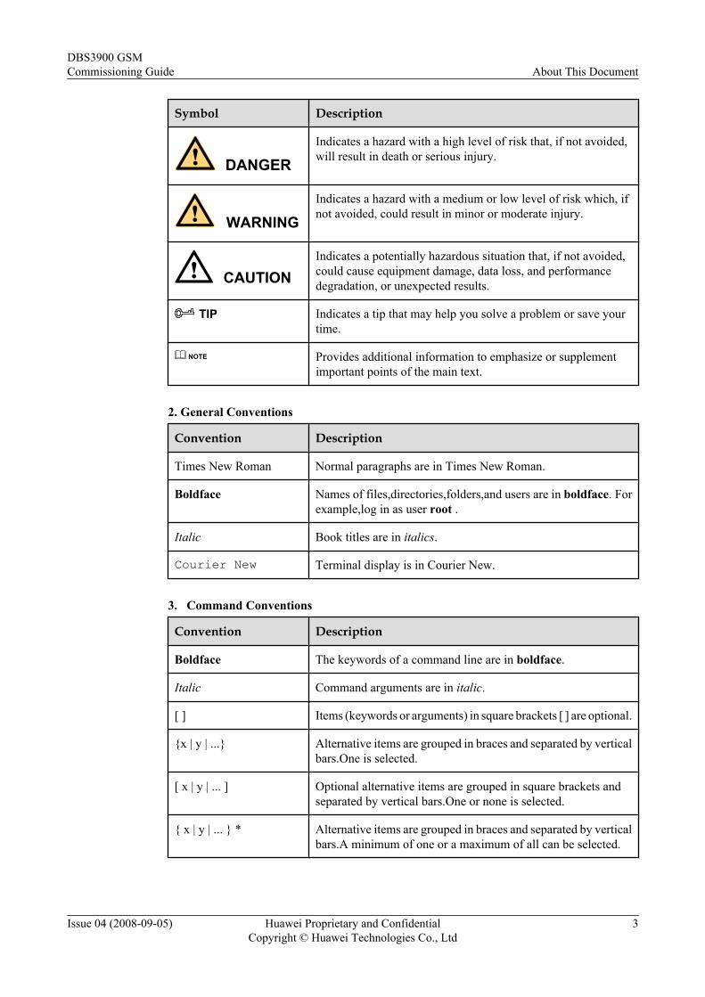
Symbol Description
DANGERIndicates a hazard with a high level of risk that, if not avoided,will result in death or serious injury.
WARNINGIndicates a hazard with a medium or low level of risk which, ifnot avoided, could result in minor or moderate injury.
CAUTIONIndicates a potentially hazardous situation that, if not avoided,could cause equipment damage, data loss, and performancedegradation, or unexpected results.
TIP Indicates a tip that may help you solve a problem or save yourtime.
NOTE Provides additional information to emphasize or supplementimportant points of the main text.
2. General Conventions
Convention Description
Times New Roman Normal paragraphs are in Times New Roman.
Boldface Names of files,directories,folders,and users are in boldface. Forexample,log in as user root .
Italic Book titles are in italics.
Courier New Terminal display is in Courier New.
3. Command Conventions
Convention Description
Boldface The keywords of a command line are in boldface.
Italic Command arguments are in italic.
[ ] Items (keywords or arguments) in square brackets [ ] are optional.
{x | y | ...} Alternative items are grouped in braces and separated by verticalbars.One is selected.
[ x | y | ... ] Optional alternative items are grouped in square brackets andseparated by vertical bars.One or none is selected.
{ x | y | ... } * Alternative items are grouped in braces and separated by verticalbars.A minimum of one or a maximum of all can be selected.
DBS3900 GSMCommissioning Guide About This Document
Issue 04 (2008-09-05) Huawei Proprietary and ConfidentialCopyright © Huawei Technologies Co., Ltd
3
Convention Description
[ x | y | ... ] * Alternative items are grouped in braces and separated by verticalbars.A minimum of zero or a maximum of all can be selected.
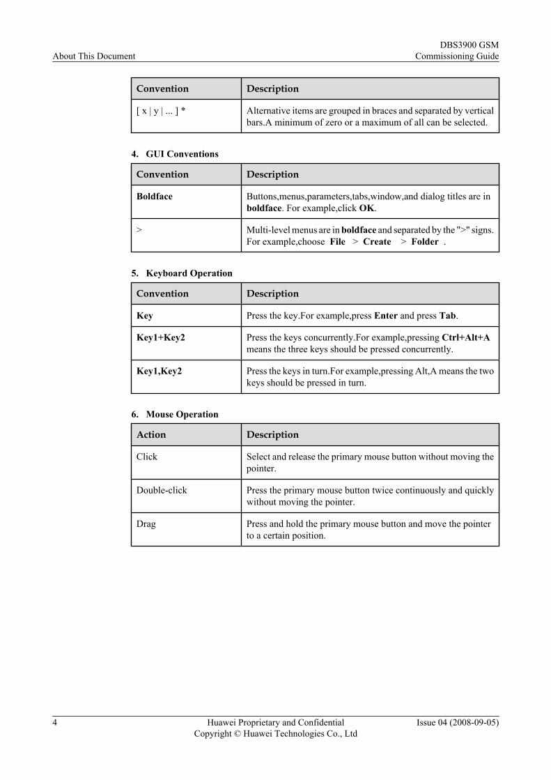
4. GUI Conventions
Convention Description
Boldface Buttons,menus,parameters,tabs,window,and dialog titles are inboldface. For example,click OK.
> Multi-level menus are in boldface and separated by the ">" signs.For example,choose File > Create > Folder .
5. Keyboard Operation
Convention Description
Key Press the key.For example,press Enter and press Tab.
Key1+Key2 Press the keys concurrently.For example,pressing Ctrl+Alt+Ameans the three keys should be pressed concurrently.
Key1,Key2 Press the keys in turn.For example,pressing Alt,A means the twokeys should be pressed in turn.
6. Mouse Operation
Action Description
Click Select and release the primary mouse button without moving thepointer.
Double-click Press the primary mouse button twice continuously and quicklywithout moving the pointer.
Drag Press and hold the primary mouse button and move the pointerto a certain position.
About This DocumentDBS3900 GSM
Commissioning Guide
4 Huawei Proprietary and ConfidentialCopyright © Huawei Technologies Co., Ltd
Issue 04 (2008-09-05)
1 Safety Information
1.1 Safety PrecautionsThis section describes certain safety precautions and helps to choose the measurement deviceand testing device. Read and follow these safety precautions before installing, operating, andmaintaining Huawei devices.
Following All Safety Precautions
Before any operation, read the instructions and precautions in this document carefully tominimize the possibility of accidents.
The Danger, Caution, and Note items in the package of documents do not cover all the safetyprecautions that must be followed. They only provide the generic safety precautions foroperations.
Symbols
DANGERThis symbol indicates that casualty or serious accident may occur if you ignore the safetyinstruction.
CAUTIONThis symbol indicates that serious or major injury may occur if you ignore the safety instruction.
NOTE
This symbol indicates that the operation may be easier if you pay attention to the safety instruction.
DBS3900 GSMCommissioning Guide 1 Safety Information
Issue 04 (2008-09-05) Huawei Proprietary and ConfidentialCopyright © Huawei Technologies Co., Ltd
1-1
Complying with the Local Safety Regulations
When operating the device, comply with the local safety regulations. The safety precautionsprovided in the documents are supplementary. You must comply with the local safetyregulations.
General Installation Requirements
The personnel in charge of installation and maintenance must be trained and master the correctoperating methods and safety precautions before beginning work.
The rules for installing and maintaining the device are as follows:
l Only the trained and qualified personnel can install, operate and maintain the device.
l Only the qualified specialists are allowed to remove the safety facilities, and repair thedevice.
l Any replacement of the device or part of the device (including the software) or any changemade to the device must be performed by qualified or authorized personnel of Huawei.
l Any fault or error that might cause safety problems must be reported immediately to thepersonnel in charge.
Grounding Requirements
The following requirements are applicable to the device to be grounded:
l Ground the device before installation and remove the ground cable after uninstallation.
l Do not operate the device in the absence of a ground conductor. Do not damage the groundconductor.
l The unit (or system) must be permanently connected to the protection ground beforeoperation. Check the electrical connection of the device before operation and ensure thatthe device is reliably grounded.
Safety of Personnel
Ensure the following:
l When lightning strikes, do not operate the device and cables.
l When lightning strikes, unplug the AC power connector. Do not use the fixed terminal ortouch the terminal or antenna connector.
NOTE
The previous two requirements are suitable for the wireless fixed terminal.
l To prevent electric shock, do not connect safety extra-low voltage (SELV) circuits totelecommunication network voltage (TNV) circuits.
l To prevent laser radiation from injuring your eyes, never look into the optical fiber outletwith unaided eyes.
l To prevent electric shock and burns, wear the electrostatic discharge (ESD) clothing, glovesand wrist strap, and remove conductors such as jewelry and watch before operation.
1 Safety InformationDBS3900 GSM
Commissioning Guide
1-2 Huawei Proprietary and ConfidentialCopyright © Huawei Technologies Co., Ltd
Issue 04 (2008-09-05)
Device Safetyl Before operation, the device must be secured on the floor or other fixed objects, such as
the walls and the mounting racks.l Do not block ventilation openings while the system is running.
l When installing the panel, tighten the screw with the tool.
1.2 Electricity Safety
High Voltage
DANGERl The high voltage power supply provides power for running the system. Direct contact with
the high voltage power supply or contact through damp objects may result in fatal danger.l Non-standard and improper high voltage operations may result in fire and electric shock.
l The personnel who install the AC facility must be qualified to perform operations on highvoltage and AC power supply facilities.
l When installing the AC power supply facility, follow the local safety regulations.
l When operating the AC power supply facility, follow the local safety regulations.
l When operating the high voltage and AC power supply facilities, use the specific toolsinstead of common tools.
l When the operation is performed in a damp environment, ensure that water is kept off thedevice. If the cabinet is damp or wet, shut down the power supply immediately.
ThunderstormThe following requirements are suitable only for the wireless base station or the device with anantenna or GPS antenna.
DANGERIn a thunderstorm, do not perform operations on high voltage and AC power supply facilities oron a steel tower and mast.
High Electrical Leakage
CAUTIONGround the device before powering on the device. Otherwise, the personnel and device are indanger.
DBS3900 GSMCommissioning Guide 1 Safety Information
Issue 04 (2008-09-05) Huawei Proprietary and ConfidentialCopyright © Huawei Technologies Co., Ltd
1-3
If the "high electrical leakage" flag is stuck to the power terminal of the device, you must groundthe device before powering it on.
Power Cable
CAUTIONDo not install and remove the power cable with a live line. Transient contact between the coreof the power cable and the conductor may generate electric arc or spark, which may cause fireor eye injury.
l Before installing or removing the power cable, turn off the power switch.
l Before connecting the power cable, ensure that the power cable and label comply with therequirements of the actual installation.
Fuse
CAUTIONTo ensure that the system runs safely, when a fuse blows, replace it with a fuse of the same typeand specifications.
Electrostatic Discharge
CAUTIONThe static electricity generated by the human body may damage the electrostatic sensitivecomponents on the circuit board, such as the large-scale integrated circuit (LIC).
In the following situations, the human body generates a static electromagnetic field:
l Movement of body parts
l Clothes friction
l Friction between shoes and the ground
l Holding plastic in hand
The static electromagnetic field will remain within the human body for a long time.
Before contacting the device, plug boards, circuit boards, and application specific integratedcircuits (ASICs), wear a grounded ESD wrist strap. It can prevent the sensitive components frombeing damaged by the static electricity in the human body.
Figure 1-1shows how to wear an ESD wrist strap.
1 Safety InformationDBS3900 GSM
Commissioning Guide
1-4 Huawei Proprietary and ConfidentialCopyright © Huawei Technologies Co., Ltd
Issue 04 (2008-09-05)
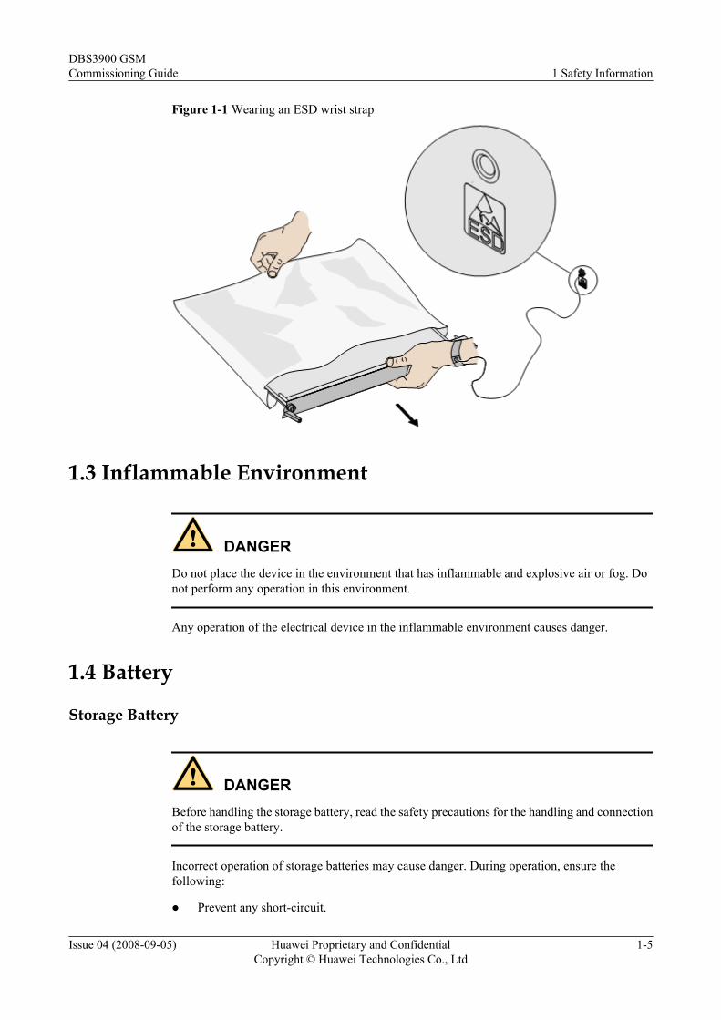
Figure 1-1 Wearing an ESD wrist strap
1.3 Inflammable Environment
DANGERDo not place the device in the environment that has inflammable and explosive air or fog. Donot perform any operation in this environment.
Any operation of the electrical device in the inflammable environment causes danger.
1.4 Battery
Storage Battery
DANGERBefore handling the storage battery, read the safety precautions for the handling and connectionof the storage battery.
Incorrect operation of storage batteries may cause danger. During operation, ensure thefollowing:
l Prevent any short-circuit.
DBS3900 GSMCommissioning Guide 1 Safety Information
Issue 04 (2008-09-05) Huawei Proprietary and ConfidentialCopyright © Huawei Technologies Co., Ltd
1-5
l Prevent the electrolyte from overflowing and leakage.
Electrolyte overflow may damage the device. It will corrode the metal parts and the circuitboards, and ultimately damage the device and cause short-circuit of the circuit boards.
General OperationsBefore installing and maintaining the storage battery, ensure the following:
l Use special insulation tools.
l Use eye protection devices and operate with care.
l Wear rubber gloves and an apron in case of an electrolyte overflow.
l Always keep the battery upright when moving. Do not place the battery upside down or tiltit.
Short-Circuit
DANGERShort-circuit of the battery may cause injury. Although the voltage of a battery is low, hightransient current generated by short-circuit will release a surge of power.
Keep metal objects away from the battery to prevent short circuit. If they have to be used,disconnect the battery in use before performing any other operation.
Harmful Gas
CAUTIONl Do not use unsealed lead-acid storage batteries, because the gas emitted from it may result
in fire or device corrosion.l Lay the storage battery horizontally and fix it properly.
The lead-acid storage battery in use will emit flammable gas. Therefore, store it in a place withgood ventilation and take precautions against fire.
High Temperature
CAUTIONHigh temperature may result in distortion, damage, and electrolyte overflow of the battery.
When the temperature of the battery exceeds 60oC, check whether there is acid overflow. If acidoverflow occurs, handle the acid immediately.
1 Safety InformationDBS3900 GSM
Commissioning Guide
1-6 Huawei Proprietary and ConfidentialCopyright © Huawei Technologies Co., Ltd
Issue 04 (2008-09-05)
Acid
CAUTIONIf the acid overflows, it should be absorbed and neutralized immediately.
When handling a leaky battery, protect against the possible damage caused by the acid. Use thefollowing materials to absorb and neutralize acid spills:
l Sodium bicarbonate (baking soda): NaHCO3
l Sodium carbonate (soda): Na2CO3
Antacids must be used according to the instructions provided by the battery manufacturer.
Lithium Battery
CAUTIONThere is danger of explosion if the battery is incorrectly replaced.
l Replace the lithium battery with the same or equivalent type recommended by themanufacturer.
l Dispose of the used battery according to the instructions provided by the manufacturer.
l Do not dispose of the lithium battery in fire.
1.5 Radiation
Electromagnetic Field Exposure
CAUTIONHigh power radio-frequency signals are harmful to human body.
Before installing or maintaining an antenna on a steel tower or mast with a large number oftransmitter antennas, the operator should coordinate with all parties to ensure that the transmitterantennas are shut down.
The base transceiver station (BTS) has RF radiation (radiation hazard). Suggestions for theinstallation and operation of BTSs are given in the following section. Operators are also requiredto comply with the related local regulations on erecting BTSs.
l The antenna should be located in an area that is inaccessible to the public where the RFradiation exceeds the stipulated value.
DBS3900 GSMCommissioning Guide 1 Safety Information
Issue 04 (2008-09-05) Huawei Proprietary and ConfidentialCopyright © Huawei Technologies Co., Ltd
1-7
l If the areas where RF radiation exceeds the stipulated value are accessible to workers,ensure that workers know where these areas are. They can shut down the transmitters beforeentering these areas. Such areas may not exist; but if they exist, the areas must be within arange of less than 10 m around the antennas.
l Each forbidden zone should be indicated by a physical barrier and striking sign to warn thepublic or workers.
Laser
CAUTIONWhen handling optical fibers, do not stand close to, or look into the optical fiber outlet withunaided eyes.
Laser transceivers or transmitters are used in the optical transmission system and associated testtools. Because the laser that is transmitted through the optical fiber produces a small beam oflight, it has a very high power density and is invisible to human eyes. If a beam of light entersthe eye, the retina may be damaged.
Normally, staring into the end of an unterminated optical fiber or broken optical fiber with theunaided eyes from a distance of more than 150 mm [5.91 in.] will not cause eye injury. Eyesmay, however, be damaged if an optical tool such as a microscope, magnifying glass or eyeloupe is used to stare into the bare optical fiber end.
Read the following guidelines to prevent laser radiation:
l Only the trained and authorized personnel can perform the operation.
l Wear a pair of eye-protective glasses when you are handling lasers or optical fibers.
l Ensure that the optical source is switched off before disconnecting optical fiber connectors.
l Never look into the end of an exposed optical fiber or an open connector if you cannotensure that the optical source is switched off.
l To ensure that the optical source is switched off, use an optical power meter.
l Before opening the front door of an optical transmission system, ensure that you are notexposed to laser radiation.
l Never use an optical tool such as a microscope, a magnifying glass, or an eye loupe to lookinto the optical fiber connector or end.
Read the following instructions before handling optical fibers:
l Only the trained personnel can cut and splice optical fibers.
l Before cutting or splicing an optical fiber, ensure that the optical fiber is disconnected fromthe optical source. After disconnecting the optical fiber, use protecting caps to protect allthe optical connectors.
1 Safety InformationDBS3900 GSM
Commissioning Guide
1-8 Huawei Proprietary and ConfidentialCopyright © Huawei Technologies Co., Ltd
Issue 04 (2008-09-05)
1.6 Working at Heights
CAUTIONWhen working at heights, ensure that the objects do not fall.
When working at heights, ensure that the following requirements must be met:
l The personnel who work at heights must be trained.
l The operating machines and tools should be carried and handled safely to prevent themfrom falling.
l Safety measures, such as wearing a helmet and a safety belt, should be taken.
l In cold regions, warm clothes should be worn before working at heights.
l Ensure that the lifting appliances are well prepared for working at heights.
Lifting Weights
CAUTIONDo not access the areas under the arm of the crane and the goods in suspension when liftingweights.
l Ensure that the operators have been trained and qualified.
l Check the weight lifting tools and ensure that they are intact.
l Lift the weight only when the weight lifting tools are firmly mounted onto the weight-bearing object or the wall.
l Use a concise instruction to prevent incorrect operation.
l The angle between the two cables should be less than or equal to 90o in the lifting of weights(See Figure 1-2).
DBS3900 GSMCommissioning Guide 1 Safety Information
Issue 04 (2008-09-05) Huawei Proprietary and ConfidentialCopyright © Huawei Technologies Co., Ltd
1-9
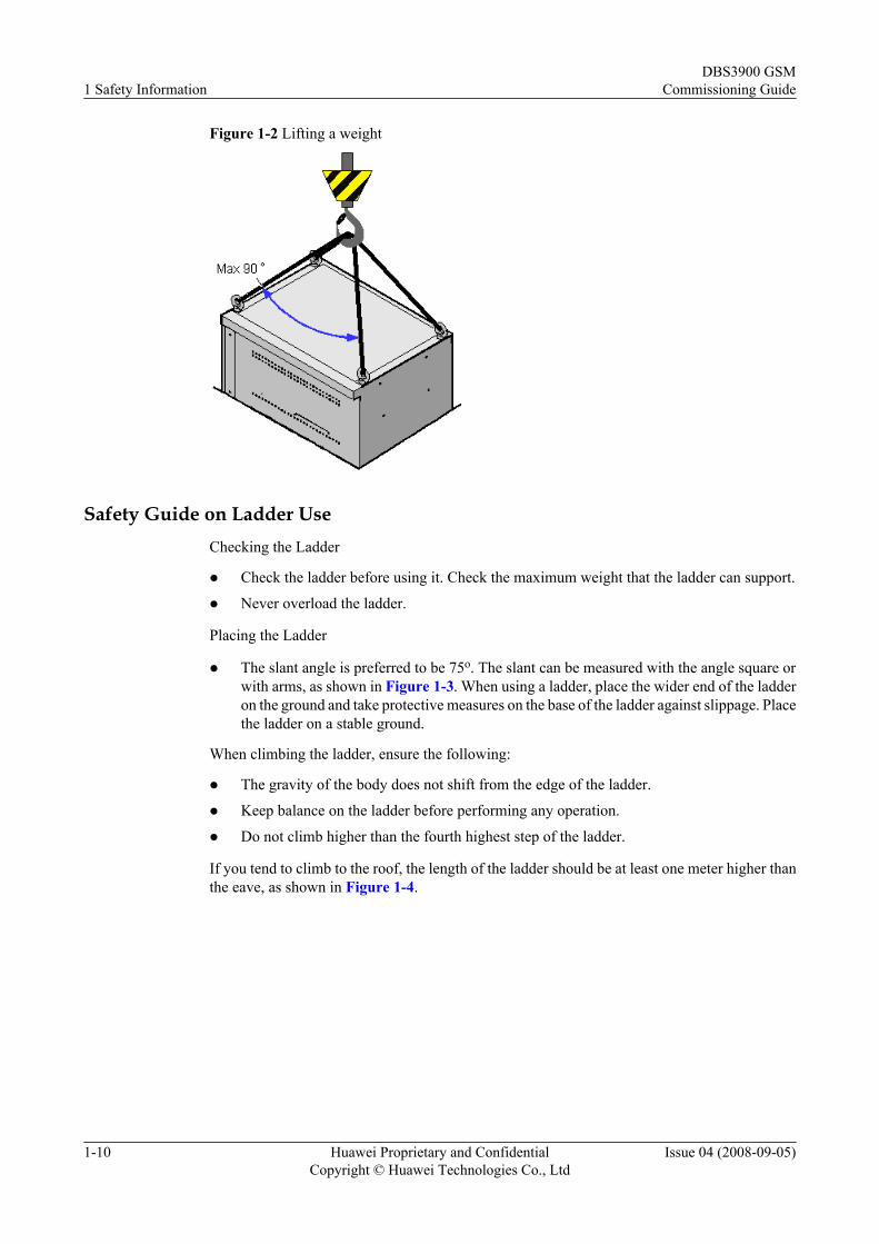
Figure 1-2 Lifting a weight
Safety Guide on Ladder UseChecking the Ladder
l Check the ladder before using it. Check the maximum weight that the ladder can support.
l Never overload the ladder.
Placing the Ladder
l The slant angle is preferred to be 75o. The slant can be measured with the angle square orwith arms, as shown in Figure 1-3. When using a ladder, place the wider end of the ladderon the ground and take protective measures on the base of the ladder against slippage. Placethe ladder on a stable ground.
When climbing the ladder, ensure the following:
l The gravity of the body does not shift from the edge of the ladder.
l Keep balance on the ladder before performing any operation.
l Do not climb higher than the fourth highest step of the ladder.
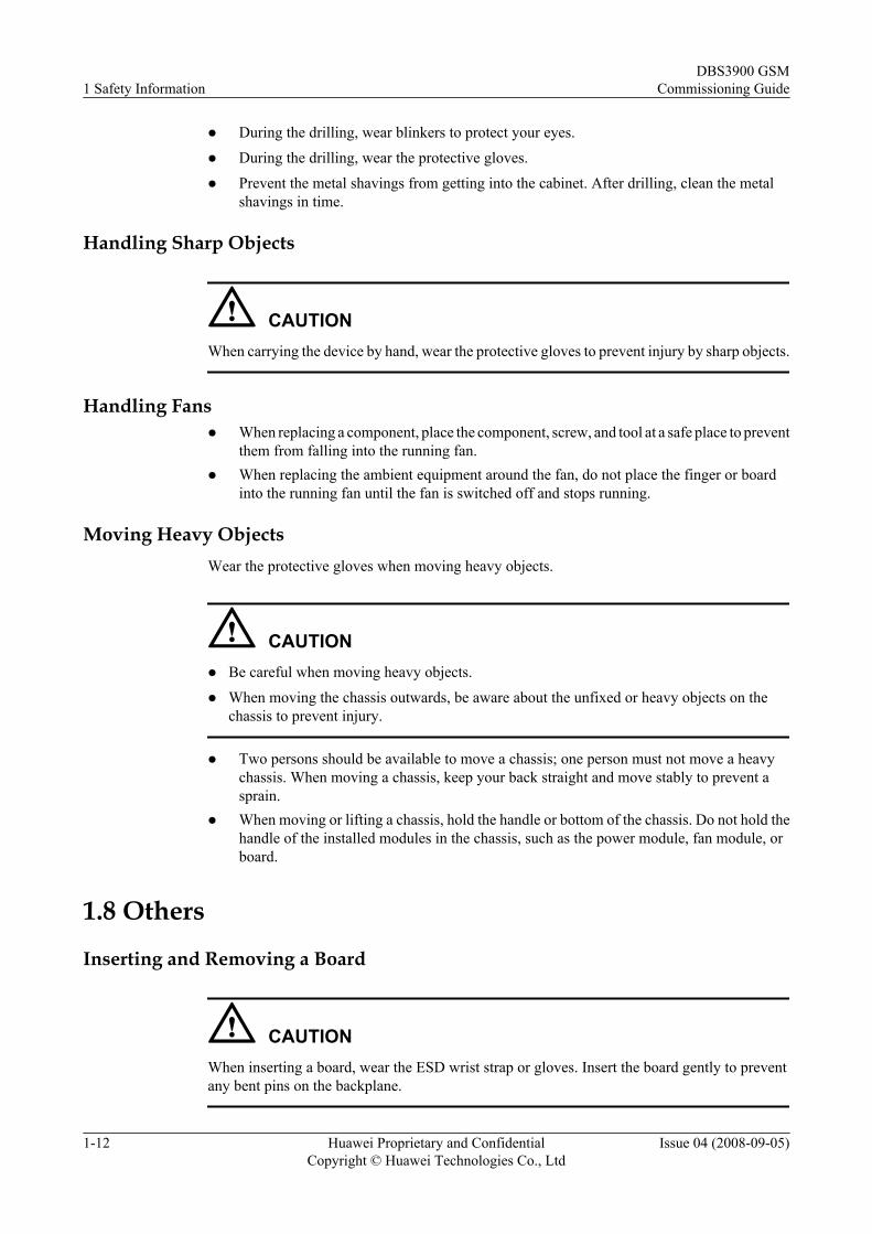
If you tend to climb to the roof, the length of the ladder should be at least one meter higher thanthe eave, as shown in Figure 1-4.
1 Safety InformationDBS3900 GSM
Commissioning Guide
1-10 Huawei Proprietary and ConfidentialCopyright © Huawei Technologies Co., Ltd
Issue 04 (2008-09-05)
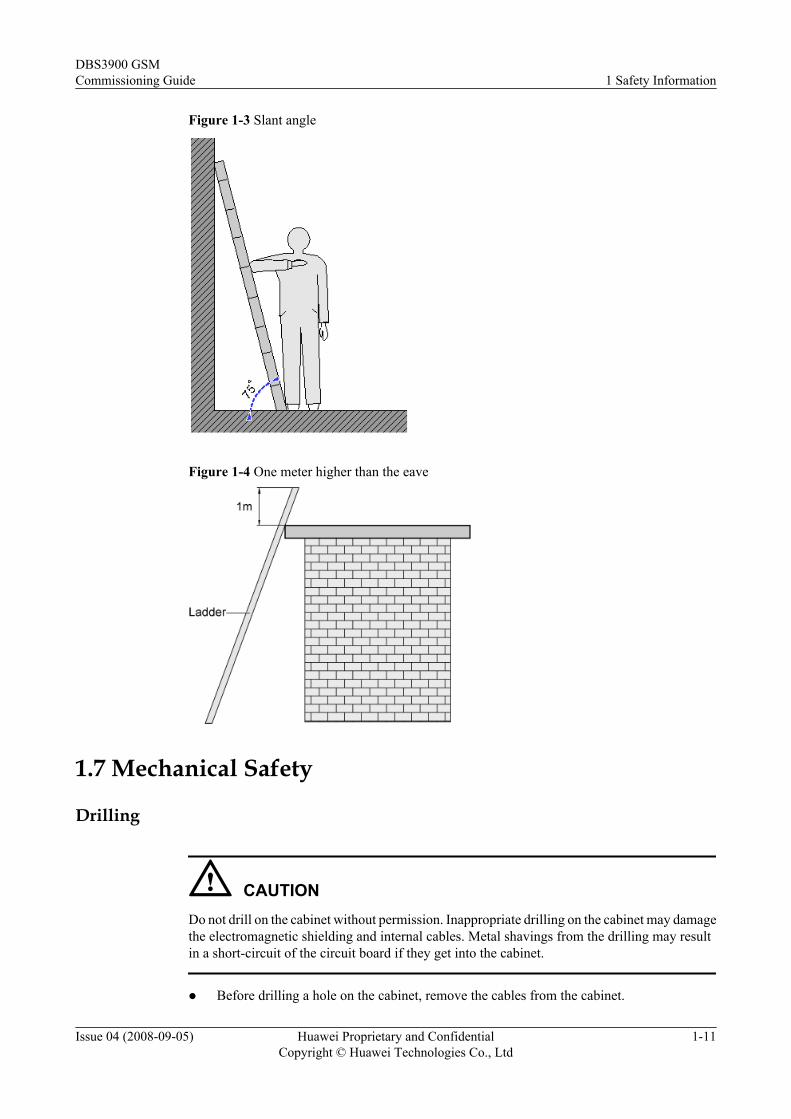
Figure 1-3 Slant angle
Figure 1-4 One meter higher than the eave
1.7 Mechanical Safety
Drilling
CAUTIONDo not drill on the cabinet without permission. Inappropriate drilling on the cabinet may damagethe electromagnetic shielding and internal cables. Metal shavings from the drilling may resultin a short-circuit of the circuit board if they get into the cabinet.
l Before drilling a hole on the cabinet, remove the cables from the cabinet.
DBS3900 GSMCommissioning Guide 1 Safety Information
Issue 04 (2008-09-05) Huawei Proprietary and ConfidentialCopyright © Huawei Technologies Co., Ltd
1-11
l During the drilling, wear blinkers to protect your eyes.
l During the drilling, wear the protective gloves.
l Prevent the metal shavings from getting into the cabinet. After drilling, clean the metalshavings in time.
Handling Sharp Objects
CAUTIONWhen carrying the device by hand, wear the protective gloves to prevent injury by sharp objects.
Handling Fansl When replacing a component, place the component, screw, and tool at a safe place to prevent
them from falling into the running fan.l When replacing the ambient equipment around the fan, do not place the finger or board
into the running fan until the fan is switched off and stops running.
Moving Heavy ObjectsWear the protective gloves when moving heavy objects.
CAUTIONl Be careful when moving heavy objects.
l When moving the chassis outwards, be aware about the unfixed or heavy objects on thechassis to prevent injury.
l Two persons should be available to move a chassis; one person must not move a heavychassis. When moving a chassis, keep your back straight and move stably to prevent asprain.
l When moving or lifting a chassis, hold the handle or bottom of the chassis. Do not hold thehandle of the installed modules in the chassis, such as the power module, fan module, orboard.
1.8 Others
Inserting and Removing a Board
CAUTIONWhen inserting a board, wear the ESD wrist strap or gloves. Insert the board gently to preventany bent pins on the backplane.
1 Safety InformationDBS3900 GSM
Commissioning Guide
1-12 Huawei Proprietary and ConfidentialCopyright © Huawei Technologies Co., Ltd
Issue 04 (2008-09-05)
l Insert the board along the guide rail.
l Avoid contact of one board with another to prevent short-circuit or damage.
l Do not remove the active board before powering off.
l When holding a board in hand, do not touch the board circuit, components, connectors, orconnection slots.
Bundling Signal Cables
CAUTIONBundle the signal cables separately from the strong current cables or high voltage cables.
Cabling RequirementsAt a very low temperature, movement of the cable may damage the plastic skin of the cable. Toensure the construction safety, comply with the following requirements:
l When installing cables, ensure that the environment temperature is above 0oC.
l If cables are stored in the place below 0oC, move the cables into a place at a roomtemperature and store the cables for more than 24 hours before installation.
l Move the cables with care, especially at a low temperature. Do not drop the cables directlyfrom the vehicle.
DBS3900 GSMCommissioning Guide 1 Safety Information
Issue 04 (2008-09-05) Huawei Proprietary and ConfidentialCopyright © Huawei Technologies Co., Ltd
1-13

2 General Requirements for DBS3900Commissioning
About This Chapter
The general requirements for DBS3900 commissioning are the commissioning prerequisites andcommissioning resources.
2.1 DBS3900 Commissioning PrerequisitesThis describes the DBS3900 commissioning prerequisites. The commissioning prerequisitesrefer to the hardware and software requirements of the DBS3900 and BSC. The requirementsmust be met before the commissioning of the DBS3900.
2.2 DBS3900 Commissioning ResourcesBefore the commissioning, you should arrange for the tools, obtain the information about theDBS3900, and download the proper software for the boards in the DBS3900.
DBS3900 GSMCommissioning Guide 2 General Requirements for DBS3900 Commissioning
Issue 04 (2008-09-05) Huawei Proprietary and ConfidentialCopyright © Huawei Technologies Co., Ltd
2-1
2.1 DBS3900 Commissioning PrerequisitesThis describes the DBS3900 commissioning prerequisites. The commissioning prerequisitesrefer to the hardware and software requirements of the DBS3900 and BSC. The requirementsmust be met before the commissioning of the DBS3900.
Prerequisites for the DBS3900l Hardware of the DBS3900, such as the cabinet, cables, antenna system, and auxiliary
equipment, is installed and passes the check.
l The DBS3900 system is successfully powered on.
Prerequisites for the BSCl The BSC is installed. The system commissioning is complete, and the system runs normally.
l The BSC is configured with the data for commissioning the DBS3900 and the data is backedup.
2.2 DBS3900 Commissioning ResourcesBefore the commissioning, you should arrange for the tools, obtain the information about theDBS3900, and download the proper software for the boards in the DBS3900.
Commissioning Mode
The commissioning is performed through the Site Maintenance Terminal System. The SiteMaintenance Terminal PC is connected to the ETH port on the panel of the BBU through thecrossover cable.
Tool
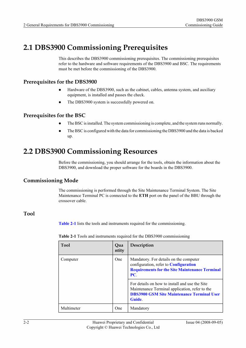
Table 2-1 lists the tools and instruments required for the commissioning.
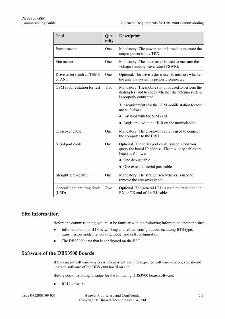
Table 2-1 Tools and instruments required for the DBS3900 commissioning
Tool Quantity
Description
Computer One Mandatory. For details on the computerconfiguration, refer to ConfigurationRequirements for the Site Maintenance TerminalPC.
For details on how to install and use the SiteMaintenance Terminal application, refer to theDBS3900 GSM Site Maintenance Terminal UserGuide.
Multimeter One Mandatory
2 General Requirements for DBS3900 CommissioningDBS3900 GSM
Commissioning Guide
2-2 Huawei Proprietary and ConfidentialCopyright © Huawei Technologies Co., Ltd
Issue 04 (2008-09-05)
Tool Quantity
Description
Power meter One Mandatory. The power meter is used to measure theoutput power of the TRX.
Site master One Mandatory. The site master is used to measure thevoltage standing wave ratio (VSWR).
Drive tester (such as TEMSor ANT)
One Optional. The drive tester is used to measure whetherthe antenna system is properly connected.
GSM mobile station for test Two Mandatory. The mobile station is used to perform thedialing test and to check whether the antenna systemis properly connected.
The requirements for the GSM mobile station for testare as follows:l Installed with the SIM card
l Registered with the HLR on the network side
Crossover cable One Mandatory. The crossover cable is used to connectthe computer to the BBU.
Serial port cable One Optional. The serial port cable is used when youquery the board IP address. The auxiliary cables arelisted as follows:l One debug cable
l One extended serial port cable
Straight screwdriver One Mandatory. The straight screwdriver is used toremove the crossover cable.
General light emitting diode(LED)
Two Optional. The general LED is used to determine theRX or TX end of the E1 cable.
Site Information
Before the commissioning, you must be familiar with the following information about the site:
l Information about BTS networking and related configuration, including BTS type,transmission mode, networking mode, and cell configuration.
l The DBS3900 data that is configured on the BSC.
Software of the DBS3900 Boards
If the current software version is inconsistent with the expected software version, you shouldupgrade software of the DBS3900 board on site.
Before commissioning, arrange for the following DBS3900 board software:
l RRU software
DBS3900 GSMCommissioning Guide 2 General Requirements for DBS3900 Commissioning
Issue 04 (2008-09-05) Huawei Proprietary and ConfidentialCopyright © Huawei Technologies Co., Ltd
2-3
l GTMU software
Before the commissioning, download the proper software of the DBS3900 boards to the SiteMaintenance Terminal PC.
CAUTIONWhen you remove the RJ45 connector of the crossover cable from the ETH port after thecommissioning, press the RJ45 connector by using a straight screwdriver, and then remove theRJ45 connector.
2 General Requirements for DBS3900 CommissioningDBS3900 GSM
Commissioning Guide
2-4 Huawei Proprietary and ConfidentialCopyright © Huawei Technologies Co., Ltd
Issue 04 (2008-09-05)
3 DBS3900 Commissioning Procedure
This describes how to commission the DBS3900.
Prerequisitel The commissioning requirements are met.
l The commissioning resources are ready.
Procedure
Step 1 Starting the Site Maintenance Terminal System
1. Set the IP address of the Site Maintenance Terminal PC by referring to 4.1 Setting the IPAddress of the Site Maintenance Terminal PC.
2. Connect the Site Maintenance Terminal PC to the BTS by referring to 4.2 Connecting theSite Maintenance Terminal PC to the BTS.
3. Log in to the BTS by referring to 4.3 Locally Logging In to the BTS.
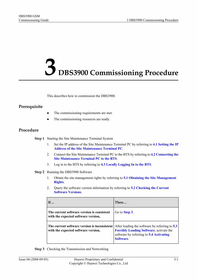
Step 2 Running the DBS3900 Software
1. Obtain the site management rights by referring to 5.1 Obtaining the Site ManagementRights.
2. Query the software version information by referring to 5.2 Checking the CurrentSoftware Versions.
If… Then…
The current software version is consistentwith the expected software version,
Go to Step 3.
The current software version is inconsistentwith the expected software version,
After loading the software by referring to 5.3Forcibly Loading Software, activate thesoftware by referring to 5.4 ActivatingSoftware.
Step 3 Checking the Transmission and Networking
DBS3900 GSMCommissioning Guide 3 DBS3900 Commissioning Procedure
Issue 04 (2008-09-05) Huawei Proprietary and ConfidentialCopyright © Huawei Technologies Co., Ltd
3-1
1. Check the transmission between the BBU and the RRU by referring to 6.1 Checking theTransmission Between the BBU and the RRU.
2. Check the transmission between the BBU and the BSC by referring to 6.2 Checking theTransmission Between the BBU and the BSC.
3. Check the consistency between actual networking and data configuration by referring to6.3 Checking the Consistency Between Actual Networking and Data Configuration.
Step 4 Commission the antenna system.
1. Check the antenna connection by referring to 7.2 Checking the Antenna Connection.
2. Measure the VSWR on the antenna port by referring to 7.1 Measuring the VSWR at theAntenna Port.
3. Measure the output power of the TRX by referring to 7.3 Measuring the Output Powerof the TRX.
Step 5 Checking the operating status of the DBS3900
1. Check the status of the DBS3900 LEDs by referring to 8.1 Checking the Status of theDBS3900 LEDs.
2. Check the alarm information of the DBS3900 by referring to 8.2 Checking the AlarmInformation of the DBS3900.
3. Perform the loopback test by referring to 8.3 Performing the Loopback Test.
Step 6 Testing the DBS3900 Services
1. Perform the loopback test of a channel by referring to 9.1 Performing the Loopback Testof a Channel.
2. Test the CS services by referring to 9.2 Testing CS Services.
3. Test the PS services by referring to 9.3 Testing PS Services.
Step 7 Set the environment parameters by referring to 10.2 Monitoring Environment.
Step 8 Record the commissioning procedure and the problems in the 12 Data Sheet forCommissioning, and export the commissioning report.
CAUTIONAfter the commissioning procedure, release the site management rights on the Site MaintenanceTerminal System. In the case of the commissioning is performed on the Site MaintenanceTerminal System and the communication between the BTS and the BSC is normal, the SiteMaintenance Terminal System automatically releases the site management rights when thefailure of communication between the Site Maintenance Terminal PC and the BBU lasts morethan 15 minutes.
NOTE
To troubleshoot the problems encountered in the commissioning procedure, refer to 11 FAQs for BTSCommissioning.
----End
3 DBS3900 Commissioning ProcedureDBS3900 GSM
Commissioning Guide
3-2 Huawei Proprietary and ConfidentialCopyright © Huawei Technologies Co., Ltd
Issue 04 (2008-09-05)
4 Starting the Site Maintenance TerminalSystem
About This Chapter
Before starting the Site Maintenance Terminal, firstly, set the IP address of the Site MaintenanceTerminal PC; secondly, connect the Site Maintenance Terminal PC to the BTS; finally, log into the Site Maintenance Terminal.
4.1 Setting the IP Address of the Site Maintenance Terminal PCThis describes how to set the IP address of the Site Maintenance Terminal PC to the same networksegment as the IP address (192.168.0.72/255.255.255.0) of the BTS.
4.2 Connecting the Site Maintenance Terminal PC to the BTSThe Site Maintenance Terminal PC should be connected to the ETH port on the main controlmodule of the BTS through the crossover cable. Then, you can operate and maintain the BTSon the Site Maintenance Terminal.
4.3 Locally Logging In to the BTSYou can run the Site Maintenance Terminal to directly log in to the BTS.
DBS3900 GSMCommissioning Guide 4 Starting the Site Maintenance Terminal System
Issue 04 (2008-09-05) Huawei Proprietary and ConfidentialCopyright © Huawei Technologies Co., Ltd
4-1
4.1 Setting the IP Address of the Site Maintenance TerminalPC
This describes how to set the IP address of the Site Maintenance Terminal PC to the same networksegment as the IP address (192.168.0.72/255.255.255.0) of the BTS.
PrerequisiteThe Site Maintenance Terminal PC is configured with the TCP/IP protocol.
Procedure
Step 1 Take the Windows XP operating system as an example. On the Windows XP operating system,choose Start > Control Panel.
Step 2 Select Network Connections. A dialog box is displayed. Right-click the Local AreaConnection icon.
Step 3 Choose Properties on the shortcut menu,. The Local Area Connection Properties dialog boxis displayed.
Step 4 Select Internet Protocol (TCP/IP).
Step 5 Click Properties. The Internet Protocol (TCP/IP) Properties dialog box is displayed.
Step 6 Select Use the following IP address.
Step 7 Enter the correct IP address, subnet mask, and default gateway. Ensure that the IP address of theSite Maintenance Terminal PC and the IP address (192.168.0.72/255.255.255.0) of the BTS arelocated in the same network segment, so that a local maintenance path can be set up.
Step 8 Click OK to complete the setting.
----End
4.2 Connecting the Site Maintenance Terminal PC to theBTS
The Site Maintenance Terminal PC should be connected to the ETH port on the main controlmodule of the BTS through the crossover cable. Then, you can operate and maintain the BTSon the Site Maintenance Terminal.
PrerequisiteThe IP address and the subnet mask of the Site Maintenance Terminal PC are set. The IP addressof the Site Maintenance Terminal PC and the IP address (192.168.0.72/255.255.255.0) of theBTS are located in the same network segment.
Procedure
Step 1 Use the crossover cable to connect the Site Maintenance Terminal PC to the BTS. One end ofthe crossover cable is connected to the ETH port on the main control module (GTMU for the
4 Starting the Site Maintenance Terminal SystemDBS3900 GSM
Commissioning Guide
4-2 Huawei Proprietary and ConfidentialCopyright © Huawei Technologies Co., Ltd
Issue 04 (2008-09-05)
DBS3900) of the main cabinet. The other end of the crossover cable is connected to the Ethernetcable port on the Site Maintenance Terminal PC (usually a portable PC).
Step 2 Start the command window.
l If the operating system of the Site Maintenance Terminal PC is Windows 98, choose Start> Program > MS-DOS Prompt. The command window is displayed.
l If the operating system of the Site Maintenance Terminal PC is Windows 2000/XP, chooseStart > Run. In the Run dialog box, run the cmd command. The command window isdisplayed.
Step 3 In the command window, run the ping target_name command to verify that the connectionbetween the PC and the DBS3900 is established.
NOTE
target_name indicates the IP address of the BTS.
If the information similar to that in the following example is returned, the LMT PC and theGBAM communicate normally. In this example, the IP address of the external network is192.168.0.72.
Pinging 192.168.0.72 with 32 bytes of data:
Reply from 192.168.0.72: bytes=32 time=1ms TTL=253
Reply from 192.168.0.72: bytes=32 time=1ms TTL=253
Reply from 192.168.0.72: bytes=32 time=1ms TTL=253
Reply from 192.168.0.72: bytes=32 time=1ms TTL=253
Ping statistics for 192.168.0.72:
Packets: Sent = 4, Received = 4, Lost = 0 (0% loss),
Approximate round trip times in milli-seconds:
Minimum = 1ms, Maximum = 1ms, Average = 1ms
----End
4.3 Locally Logging In to the BTSYou can run the Site Maintenance Terminal to directly log in to the BTS.
Prerequisitel The Site Maintenance Terminal PC is connected properly to the BTS.
l The Site Maintenance Terminal PC is installed with the latest site maintenance terminalsoftware.
Procedure
Step 1 Double-click btsm.exe to start the Site Maintenance Terminal System.
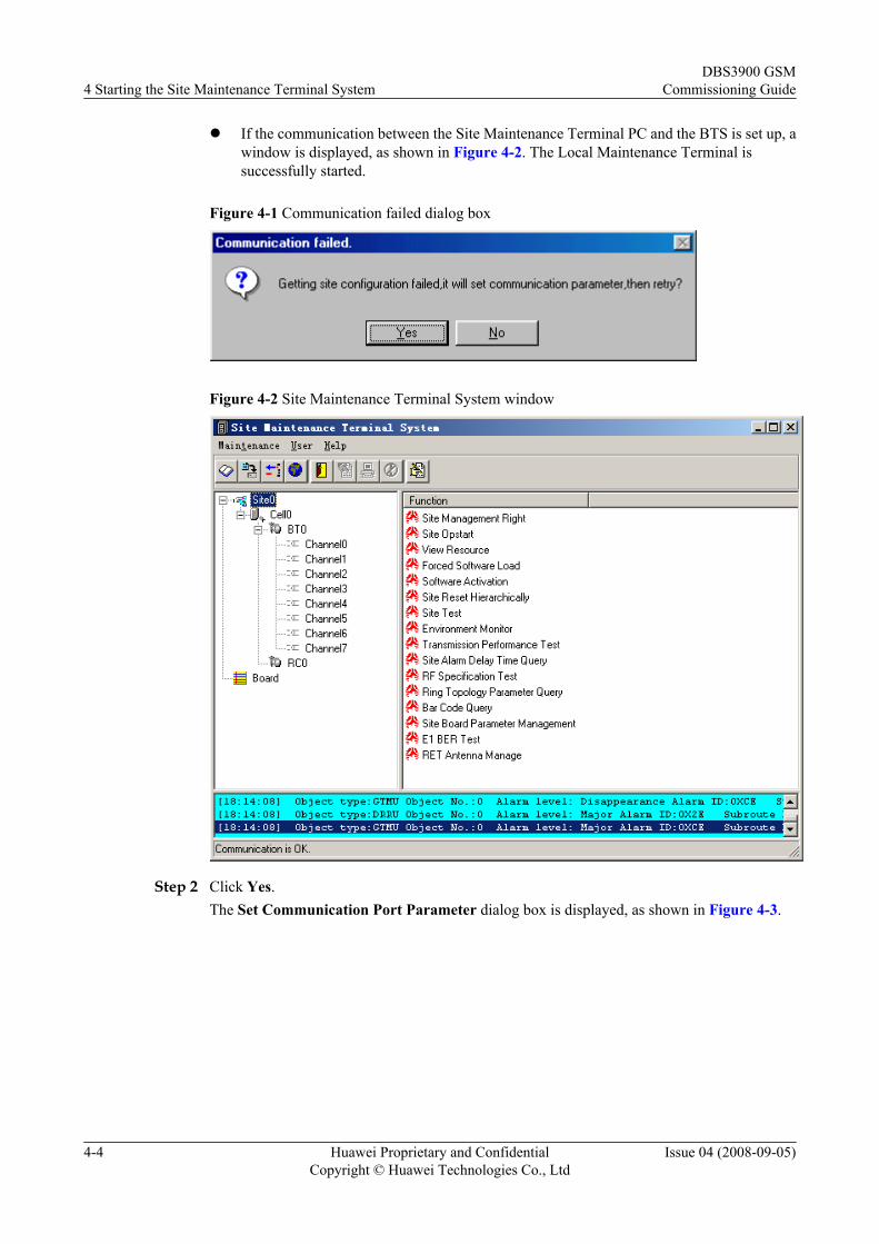
l If the communication between the Site Maintenance Terminal PC and the BTS is not setup, the Communication failed dialog box is displayed, as shown in Figure 4-1. Go toStep 2.
DBS3900 GSMCommissioning Guide 4 Starting the Site Maintenance Terminal System
Issue 04 (2008-09-05) Huawei Proprietary and ConfidentialCopyright © Huawei Technologies Co., Ltd
4-3
l If the communication between the Site Maintenance Terminal PC and the BTS is set up, awindow is displayed, as shown in Figure 4-2. The Local Maintenance Terminal issuccessfully started.
Figure 4-1 Communication failed dialog box
Figure 4-2 Site Maintenance Terminal System window
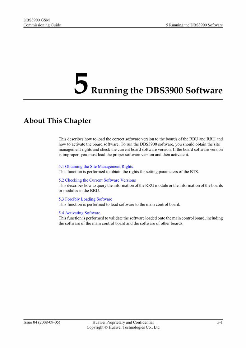
Step 2 Click Yes.The Set Communication Port Parameter dialog box is displayed, as shown in Figure 4-3.
4 Starting the Site Maintenance Terminal SystemDBS3900 GSM
Commissioning Guide
4-4 Huawei Proprietary and ConfidentialCopyright © Huawei Technologies Co., Ltd
Issue 04 (2008-09-05)
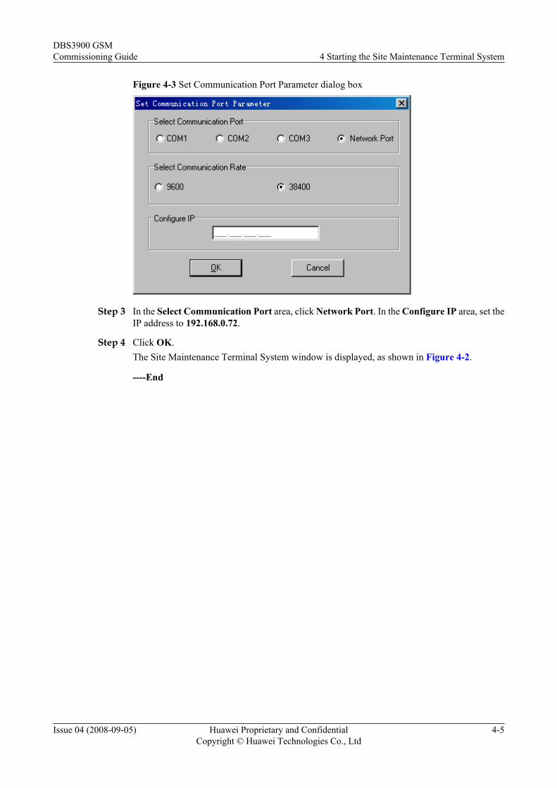
Figure 4-3 Set Communication Port Parameter dialog box
Step 3 In the Select Communication Port area, click Network Port. In the Configure IP area, set theIP address to 192.168.0.72.
Step 4 Click OK.The Site Maintenance Terminal System window is displayed, as shown in Figure 4-2.
----End
DBS3900 GSMCommissioning Guide 4 Starting the Site Maintenance Terminal System
Issue 04 (2008-09-05) Huawei Proprietary and ConfidentialCopyright © Huawei Technologies Co., Ltd
4-5

5 Running the DBS3900 Software
About This Chapter
This describes how to load the correct software version to the boards of the BBU and RRU andhow to activate the board software. To run the DBS3900 software, you should obtain the sitemanagement rights and check the current board software version. If the board software versionis improper, you must load the proper software version and then activate it.
5.1 Obtaining the Site Management RightsThis function is performed to obtain the rights for setting parameters of the BTS.
5.2 Checking the Current Software VersionsThis describes how to query the information of the RRU module or the information of the boardsor modules in the BBU.
5.3 Forcibly Loading SoftwareThis function is performed to load software to the main control board.
5.4 Activating SoftwareThis function is performed to validate the software loaded onto the main control board, includingthe software of the main control board and the software of other boards.
DBS3900 GSMCommissioning Guide 5 Running the DBS3900 Software
Issue 04 (2008-09-05) Huawei Proprietary and ConfidentialCopyright © Huawei Technologies Co., Ltd
5-1
5.1 Obtaining the Site Management RightsThis function is performed to obtain the rights for setting parameters of the BTS.
PrerequisiteYou have logged in to the BTS through the Site Maintenance Terminal.
Procedure
Step 1 In the left pane of the Site Maintenance Terminal System window, click Site. In the right paneof the window, double-click Site Management Right.The Site Management Right dialog box is displayed.
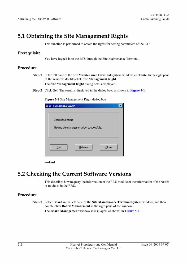
Step 2 Click Get. The result is displayed in the dialog box, as shown in Figure 5-1.
Figure 5-1 Site Management Right dialog box
----End
5.2 Checking the Current Software VersionsThis describes how to query the information of the RRU module or the information of the boardsor modules in the BBU.
Procedure
Step 1 Select Board in the left pane of the Site Maintenance Terminal System window, and thendouble-click Board Management in the right pane of the window.The Board Management window is displayed, as shown in Figure 5-2.
5 Running the DBS3900 SoftwareDBS3900 GSM
Commissioning Guide
5-2 Huawei Proprietary and ConfidentialCopyright © Huawei Technologies Co., Ltd
Issue 04 (2008-09-05)
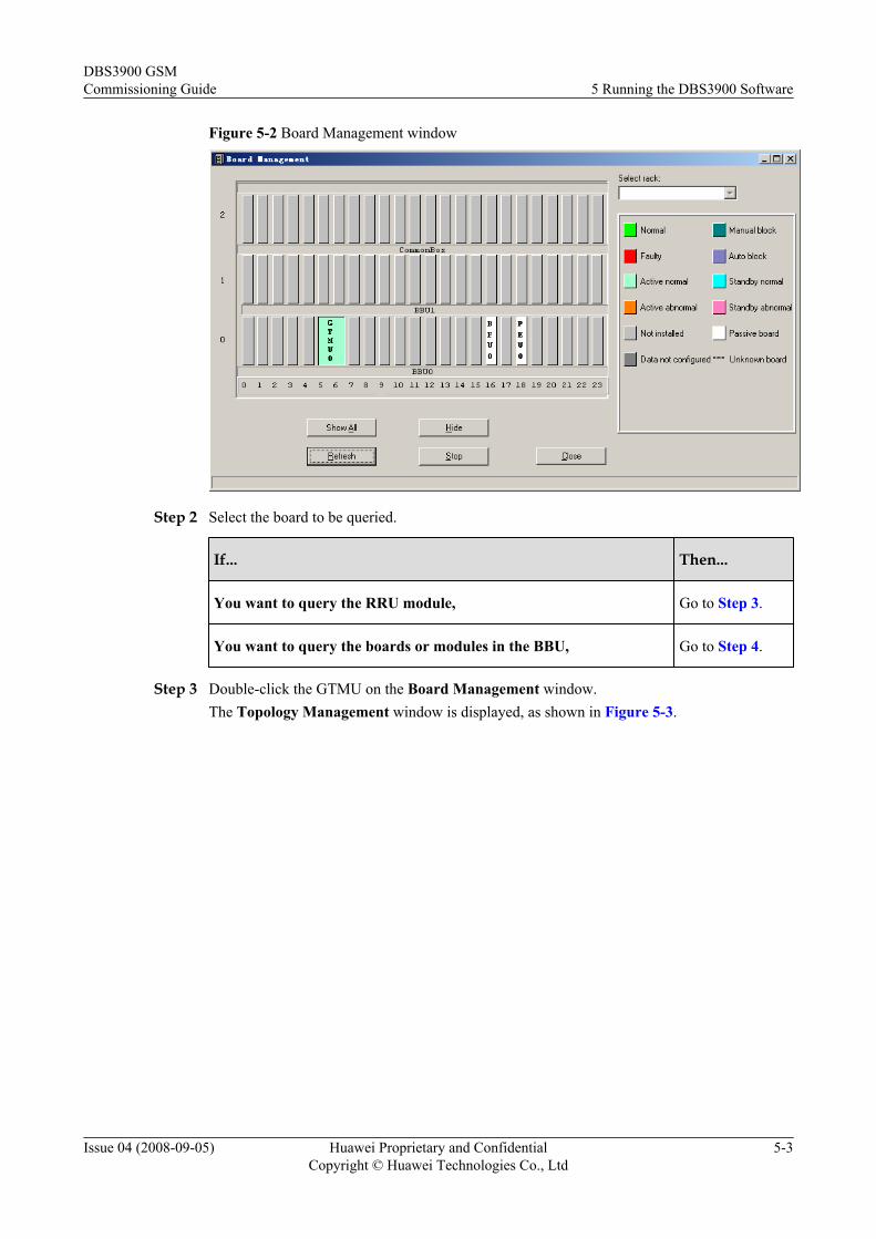
Figure 5-2 Board Management window
Step 2 Select the board to be queried.
If... Then...
You want to query the RRU module, Go to Step 3.
You want to query the boards or modules in the BBU, Go to Step 4.
Step 3 Double-click the GTMU on the Board Management window.The Topology Management window is displayed, as shown in Figure 5-3.
DBS3900 GSMCommissioning Guide 5 Running the DBS3900 Software
Issue 04 (2008-09-05) Huawei Proprietary and ConfidentialCopyright © Huawei Technologies Co., Ltd
5-3
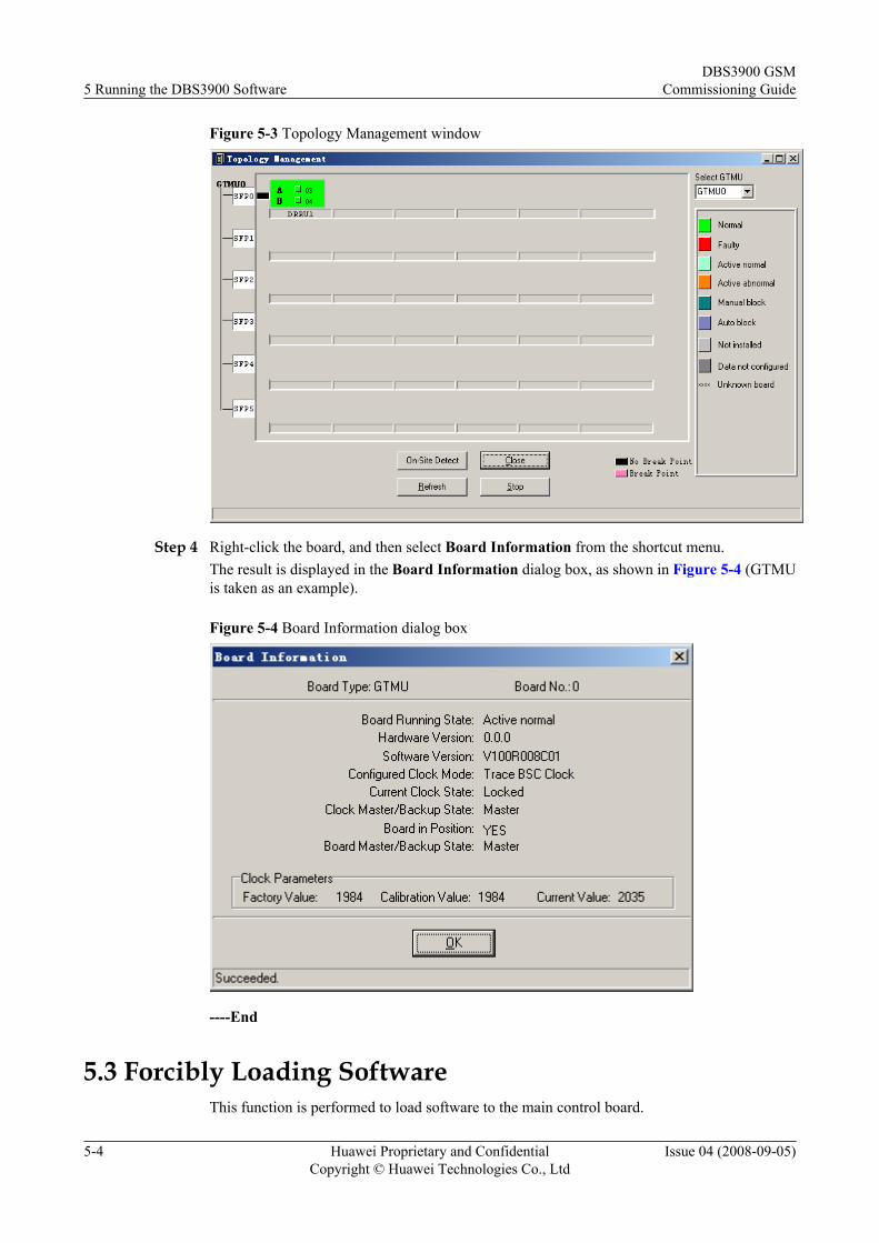
Figure 5-3 Topology Management window
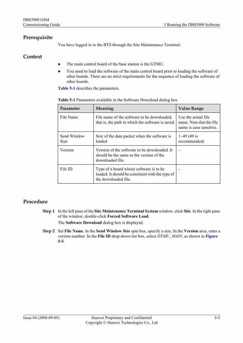
Step 4 Right-click the board, and then select Board Information from the shortcut menu.The result is displayed in the Board Information dialog box, as shown in Figure 5-4 (GTMUis taken as an example).
Figure 5-4 Board Information dialog box
----End
5.3 Forcibly Loading SoftwareThis function is performed to load software to the main control board.
5 Running the DBS3900 SoftwareDBS3900 GSM
Commissioning Guide
5-4 Huawei Proprietary and ConfidentialCopyright © Huawei Technologies Co., Ltd
Issue 04 (2008-09-05)
PrerequisiteYou have logged in to the BTS through the Site Maintenance Terminal.
Contextl The main control board of the base station is the GTMU.
l You need to load the software of the main control board prior to loading the software ofother boards. There are no strict requirements for the sequence of loading the software ofother boards.
Table 5-1 describes the parameters.
Table 5-1 Parameters available in the Software Download dialog box
Parameter Meaning Value Range
File Name File name of the software to be downloaded,that is, the path in which the software is saved
Use the actual filename. Note that the filename is case sensitive.
Send WindowSize
Size of the data packet when the software isloaded
1–49 (49 isrecommended)
Version Version of the software to be downloaded. Itshould be the same as the version of thedownloaded file.
-
File ID Type of a board whose software is to beloaded. It should be consistent with the type ofthe downloaded file.
-
Procedure
Step 1 In the left pane of the Site Maintenance Terminal System window, click Site. In the right paneof the window, double-click Forced Software Load.The Software Download dialog box is displayed.
Step 2 Set File Name. In the Send Window Size spin box, specify a size. In the Version area, enter aversion number. In the File ID drop-down list box, select DTMU_MAIN, as shown in Figure5-5.
DBS3900 GSMCommissioning Guide 5 Running the DBS3900 Software
Issue 04 (2008-09-05) Huawei Proprietary and ConfidentialCopyright © Huawei Technologies Co., Ltd
5-5
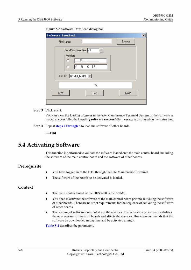
Figure 5-5 Software Download dialog box
Step 3 Click Start.You can view the loading progress in the Site Maintenance Terminal System. If the software isloaded successfully, the Loading software successfully message is displayed on the status bar.
Step 4 Repeat steps 2 through 3 to load the software of other boards.
----End
5.4 Activating SoftwareThis function is performed to validate the software loaded onto the main control board, includingthe software of the main control board and the software of other boards.
Prerequisitel You have logged in to the BTS through the Site Maintenance Terminal.
l The software of the boards to be activated is loaded.
Contextl The main control board of the DBS3900 is the GTMU.
l You need to activate the software of the main control board prior to activating the softwareof other boards. There are no strict requirements for the sequence of activating the softwareof other boards.
l The loading of software does not affect the services. The activation of software validatesthe new version software on boards and affects the services. Huawei recommends that thesoftware be downloaded in daytime and be activated at night.
Table 5-2 describes the parameters.
5 Running the DBS3900 SoftwareDBS3900 GSM
Commissioning Guide
5-6 Huawei Proprietary and ConfidentialCopyright © Huawei Technologies Co., Ltd
Issue 04 (2008-09-05)
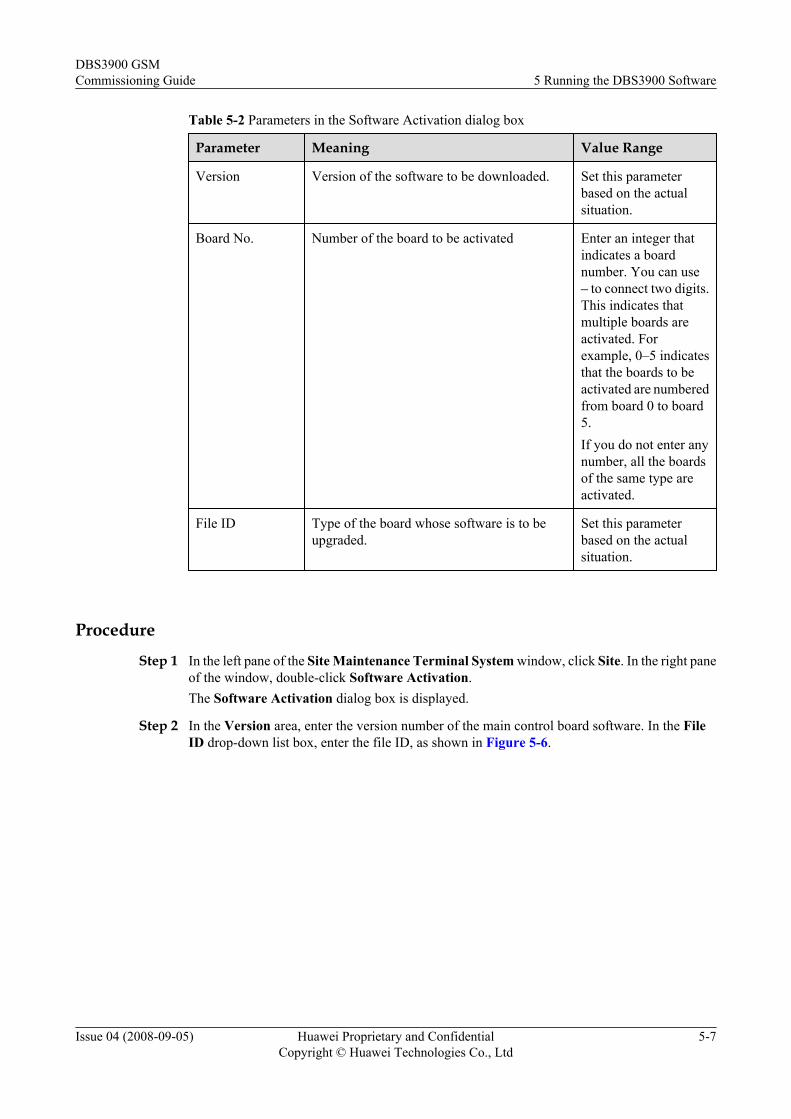
Table 5-2 Parameters in the Software Activation dialog box
Parameter Meaning Value Range
Version Version of the software to be downloaded. Set this parameterbased on the actualsituation.
Board No. Number of the board to be activated Enter an integer thatindicates a boardnumber. You can use– to connect two digits.This indicates thatmultiple boards areactivated. Forexample, 0–5 indicatesthat the boards to beactivated are numberedfrom board 0 to board5.If you do not enter anynumber, all the boardsof the same type areactivated.
File ID Type of the board whose software is to beupgraded.
Set this parameterbased on the actualsituation.
Procedure
Step 1 In the left pane of the Site Maintenance Terminal System window, click Site. In the right paneof the window, double-click Software Activation.The Software Activation dialog box is displayed.
Step 2 In the Version area, enter the version number of the main control board software. In the FileID drop-down list box, enter the file ID, as shown in Figure 5-6.
DBS3900 GSMCommissioning Guide 5 Running the DBS3900 Software
Issue 04 (2008-09-05) Huawei Proprietary and ConfidentialCopyright © Huawei Technologies Co., Ltd
5-7
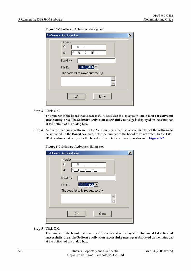
Figure 5-6 Software Activation dialog box
Step 3 Click OK.The number of the board that is successfully activated is displayed in The board list activatedsuccessfully: area. The Software activation successfully message is displayed on the status barat the bottom of the dialog box.
Step 4 Activate other board software. In the Version area, enter the version number of the software tobe activated. In the Board No. area, enter the number of the board to be activated. In the FileID drop-down list box, enter the board software to be activated, as shown in Figure 5-7.
Figure 5-7 Software Activation dialog box
Step 5 Click OK.The number of the board that is successfully activated is displayed in The board list activatedsuccessfully: area. The Software activation successfully message is displayed on the status barat the bottom of the dialog box.
5 Running the DBS3900 SoftwareDBS3900 GSM
Commissioning Guide
5-8 Huawei Proprietary and ConfidentialCopyright © Huawei Technologies Co., Ltd
Issue 04 (2008-09-05)
NOTEDuring the activation of the DRRU board software, if the Site Maintenance Terminal prompts that softwareactivation failed, check whether the communication between the BBU and the RRU is normal. Then, rectify thefault by referring to 6.1 Checking the Transmission Between the BBU and the RRU.
----End
DBS3900 GSMCommissioning Guide 5 Running the DBS3900 Software
Issue 04 (2008-09-05) Huawei Proprietary and ConfidentialCopyright © Huawei Technologies Co., Ltd
5-9

6 Checking the Transmission and Networking
About This Chapter
This describes how to check the transmission and networking of the DBS3900. The proceduresinvolve checking whether the transmission between the BBU and the RRU is normal, checkingwhether the transmission between the BBU and the BSC is normal, and checking whether thedata configuration is consistent with the actual networking of the DBS3900.
6.1 Checking the Transmission Between the BBU and the RRUTo check the transmission between the BBU and the RRU, you need to check the link statusbetween the BBU and the RRU. By checking the link status, you can rectify the fault caused byabnormal connection and therefore ensure normal communication between the BBU and theRRU.
6.2 Checking the Transmission Between the BBU and the BSCThis describes how to check the status of the LEDs on the GTMU panel, how to check theconnection of the E1 cable and E1 surge protection transfer cable, and how to rectify the faultcaused by improper connections.
6.3 Checking the Consistency Between Actual Networking and Data ConfigurationThis describes how to check the consistency between the actual networking and the dataconfiguration. The purpose is to ensure the consistency between the hardware installation andthe data configuration. The items to be checked consist of the network topologies, quantities,slot numbers, link numbers, level numbers, and configurations of the RRU and BBU.
DBS3900 GSMCommissioning Guide 6 Checking the Transmission and Networking
Issue 04 (2008-09-05) Huawei Proprietary and ConfidentialCopyright © Huawei Technologies Co., Ltd
6-1
6.1 Checking the Transmission Between the BBU and theRRU
To check the transmission between the BBU and the RRU, you need to check the link statusbetween the BBU and the RRU. By checking the link status, you can rectify the fault caused byabnormal connection and therefore ensure normal communication between the BBU and theRRU.
Procedure
Step 1 Check the CPRI0–CPRI5 LEDs on the GTMU panel of the BBU and the CPRI_W LED onthe RRU module panel. The normal status of each LED is on in green.
If... Then...
All the LEDs are in normal status, The communication between the BBU and the RRU isnormal. End the testing task.
An LED is abnormal, The communication between the BBU and the RRU isabnormal. Go to Step 2.
Step 2 Check the connections in the chain or ring to which the RRU module is connected. Theconnections consist of the connection between the BBU and the RRU, and the connectionbetween two RRU modules.1. Check the connection between the cascaded RRU modules.
l When the distance between the cascaded RRU modules is less than or equal to 5 m, useSignal Cable Between the CPRI Ports on Cascaded RRU modules to connect thecascaded RRU modules. Check whether the signal cables between the CPRI ports oncascaded RRU modules are securely attached to the connectors of the SFP modulesinserted into the CPRI_W and CPRI_E ports. Also, check whether the connectors atboth ends of this cable are normal and whether the SFP module is normal. If theconnectors or the SFP module is damaged or works improperly, replace the connectorswith new ones or replace the SFP module.
l When the distance between the cascaded RRU modules is greater than 5 m, use theoptical cable to connect the cascaded RRU modules. Check the connections of theoptical cable with the optical module on the CPRI_W and CPRI_E ports on the RRUmodule. Check the connectors at both ends of the optical cable. Check the opticalmodule. If the connector or the optical module is damaged or works improperly, replaceit with a new connector or optical module.
2. Check the connections of the optical cable with the optical module on the CPRI_W porton the RRU module and on the CPRI port on the BBU. Check the connectors at both endsof the optical cable. Check the optical module. If the connector or the optical module isdamaged or works improperly, replace it with a new connector or optical module.
3. Check the label on the optical cable between the BBU and the RRU to ensure that the opticalcable is connected correctly to the RX and TX ports on the BBU/RRU module. For detailson the mapping between RX and TX ports, refer to CPRI Optical Cable.
----End
6 Checking the Transmission and NetworkingDBS3900 GSM
Commissioning Guide
6-2 Huawei Proprietary and ConfidentialCopyright © Huawei Technologies Co., Ltd
Issue 04 (2008-09-05)
6.2 Checking the Transmission Between the BBU and theBSC
This describes how to check the status of the LEDs on the GTMU panel, how to check theconnection of the E1 cable and E1 surge protection transfer cable, and how to rectify the faultcaused by improper connections.
Prerequisitel The BBU is connected to the BSC through an E1/T1 cable.
l The BBU and the BSC are powered on.
Procedure
Step 1 Check the settings of the DIP switches on the GTMU. Ensure that the settings of DIP switchesare consistent with the on-site requirements.
Step 2 Check the operating status of the LIU0-LIU3 LEDs on the GTMU panel.
If... Then...
All the LEDs are Off, The communication between the BBU and the BSCis normal. The checking is complete.
Some LEDs are ON or blink at 4 Hz, The corresponding E1/T1 links are not normal. Go toStep 3.
NOTEYou need to check the status of only the LIU LED corresponding to the E1/T1 cable in use. The state of theLIU LED corresponding to the unused E1/T1 cable is Off.
Step 3 Check the connection and connectors at both ends of the cable. If any connector is damaged ordoes not work properly, replace it with a new connector.
If... Then...
The UELP is configured, l Check the connection between the E1/T1 cable and theOUTSIDE port on the UELP.
l Check the connection between the E1 surge protectiontransfer cable and the INSIDE port on the UELP.
l Check the connection between the E1 surge protectiontransfer cable and the E1/T1 port on the GTMU.
The UELP is not configured, Check the connection between the E1/T1 cable and the E1/T1 port on the GTMU.
DBS3900 GSMCommissioning Guide 6 Checking the Transmission and Networking
Issue 04 (2008-09-05) Huawei Proprietary and ConfidentialCopyright © Huawei Technologies Co., Ltd
6-3
Step 4 At the DDF on the BTS side, check the soldering conditions of the connectors for the E1/T1cable where communication is not normal. Ensure that the E1/T1 connectors are in goodsoldering conditions.
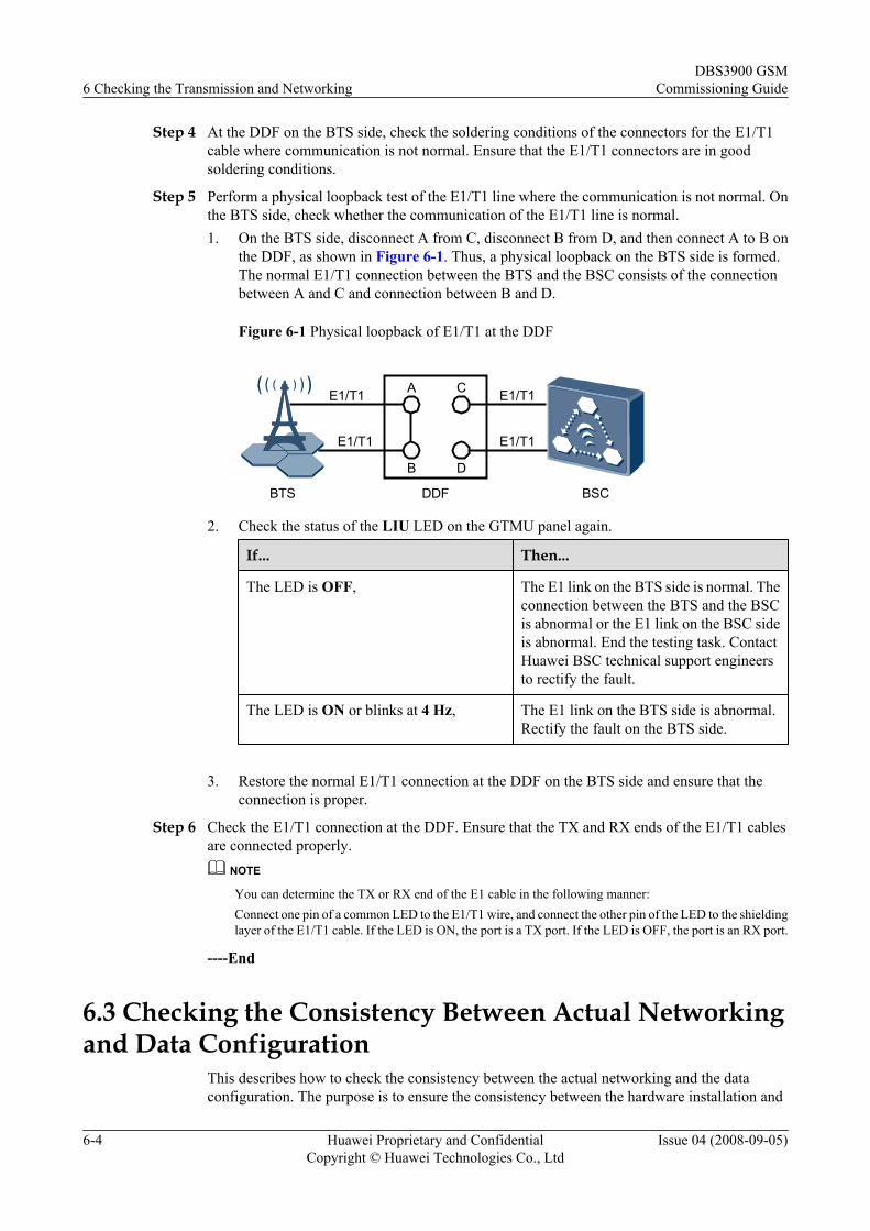
Step 5 Perform a physical loopback test of the E1/T1 line where the communication is not normal. Onthe BTS side, check whether the communication of the E1/T1 line is normal.1. On the BTS side, disconnect A from C, disconnect B from D, and then connect A to B on
the DDF, as shown in Figure 6-1. Thus, a physical loopback on the BTS side is formed.The normal E1/T1 connection between the BTS and the BSC consists of the connectionbetween A and C and connection between B and D.
Figure 6-1 Physical loopback of E1/T1 at the DDF
A
B
C
D
BTS DDF BSC
E1/T1
E1/T1 E1/T1
E1/T1
2. Check the status of the LIU LED on the GTMU panel again.
If... Then...
The LED is OFF, The E1 link on the BTS side is normal. Theconnection between the BTS and the BSCis abnormal or the E1 link on the BSC sideis abnormal. End the testing task. ContactHuawei BSC technical support engineersto rectify the fault.
The LED is ON or blinks at 4 Hz, The E1 link on the BTS side is abnormal.Rectify the fault on the BTS side.
3. Restore the normal E1/T1 connection at the DDF on the BTS side and ensure that the
connection is proper.
Step 6 Check the E1/T1 connection at the DDF. Ensure that the TX and RX ends of the E1/T1 cablesare connected properly.
NOTE
You can determine the TX or RX end of the E1 cable in the following manner:Connect one pin of a common LED to the E1/T1 wire, and connect the other pin of the LED to the shieldinglayer of the E1/T1 cable. If the LED is ON, the port is a TX port. If the LED is OFF, the port is an RX port.
----End
6.3 Checking the Consistency Between Actual Networkingand Data Configuration
This describes how to check the consistency between the actual networking and the dataconfiguration. The purpose is to ensure the consistency between the hardware installation and
6 Checking the Transmission and NetworkingDBS3900 GSM
Commissioning Guide
6-4 Huawei Proprietary and ConfidentialCopyright © Huawei Technologies Co., Ltd
Issue 04 (2008-09-05)
the data configuration. The items to be checked consist of the network topologies, quantities,slot numbers, link numbers, level numbers, and configurations of the RRU and BBU.
Prerequisitel The Site Maintenance Terminal System is started.
l The board software is loaded and activated.
l The transmission between the BBU and the RRU and the transmission between the BBUand the BSC are normal.
l The DBS3900 data configuration on the BSC side is obtained.
Background IntroductionIn the data configuration, links SFP0–SFP5 in the Topology Management window of the SiteMaintenance Terminal System correspond to the CPRI0–CPRI5 ports on the panel of the BBU.
ProcedureStep 1 Check whether the physical connection between the RRU module and the BBU and the physical
connection between the RRU modules are consistent with the link numbers, level numbers, andrelation between links in the Topology Management window by referring to NetworkTopologies of the BBU and Network Topologies of the RRU.
Step 2 Check whether the quantities of RRU modules, BBUs, and boards on the panel of each BBUare consistent with those in the Board Management window and the TopologyManagement window of the Site Maintenance Terminal System.
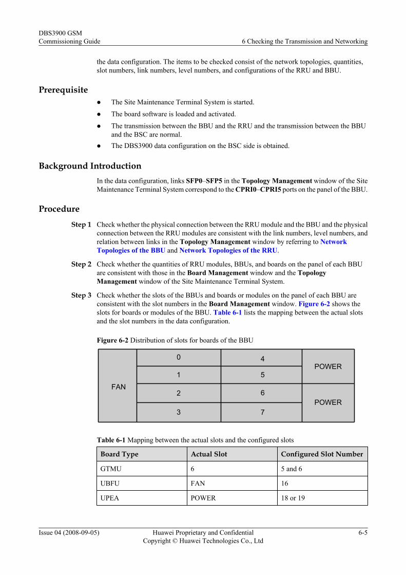
Step 3 Check whether the slots of the BBUs and boards or modules on the panel of each BBU areconsistent with the slot numbers in the Board Management window. Figure 6-2 shows theslots for boards or modules of the BBU. Table 6-1 lists the mapping between the actual slotsand the slot numbers in the data configuration.
Figure 6-2 Distribution of slots for boards of the BBU
0 4
1 5
62
3 7
FAN
POWER
POWER
Table 6-1 Mapping between the actual slots and the configured slots
Board Type Actual Slot Configured Slot Number
GTMU 6 5 and 6
UBFU FAN 16
UPEA POWER 18 or 19
DBS3900 GSMCommissioning Guide 6 Checking the Transmission and Networking
Issue 04 (2008-09-05) Huawei Proprietary and ConfidentialCopyright © Huawei Technologies Co., Ltd
6-5
NOTE
The GTMU is fixedly configured in slot 6 and occupies slots 5 and 6 of the BBU.
Step 4 Check whether the RF cable connections of the RRU modules are consistent with the RF signalRX/TX mode in the data configuration by referring to RF Cable Connections of theRRU3004.
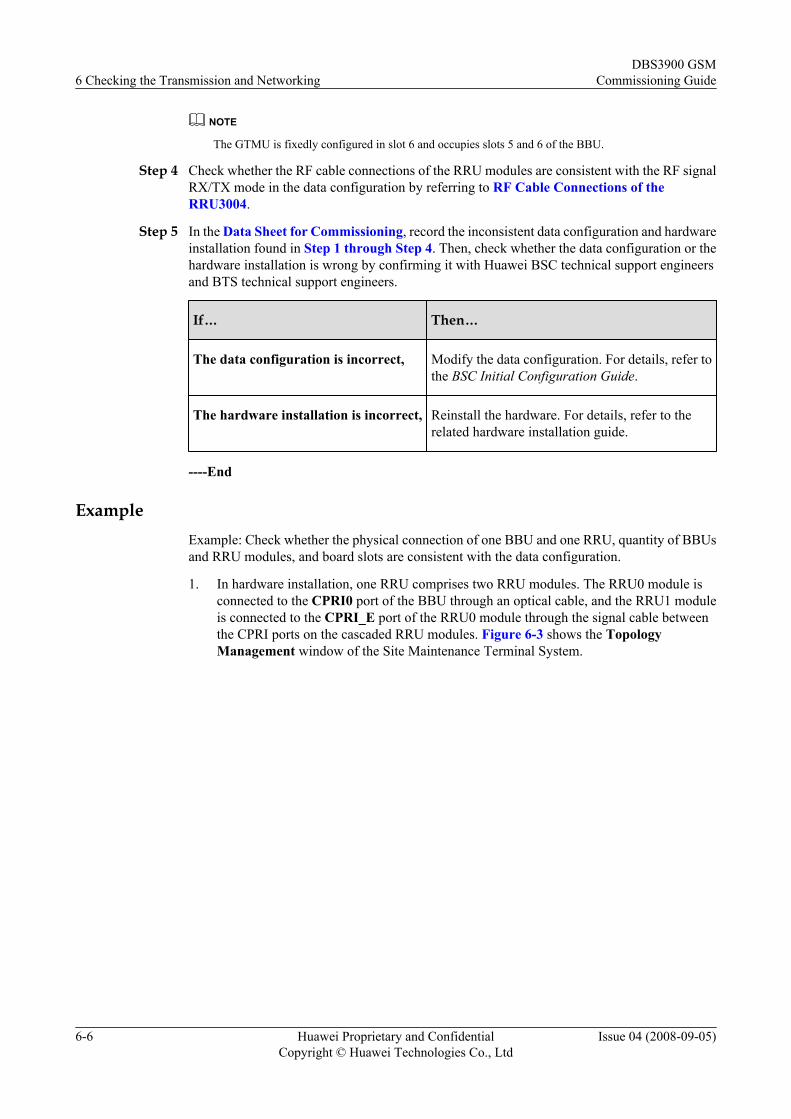
Step 5 In the Data Sheet for Commissioning, record the inconsistent data configuration and hardwareinstallation found in Step 1 through Step 4. Then, check whether the data configuration or thehardware installation is wrong by confirming it with Huawei BSC technical support engineersand BTS technical support engineers.
If… Then…
The data configuration is incorrect, Modify the data configuration. For details, refer tothe BSC Initial Configuration Guide.
The hardware installation is incorrect, Reinstall the hardware. For details, refer to therelated hardware installation guide.
----End
ExampleExample: Check whether the physical connection of one BBU and one RRU, quantity of BBUsand RRU modules, and board slots are consistent with the data configuration.
1. In hardware installation, one RRU comprises two RRU modules. The RRU0 module isconnected to the CPRI0 port of the BBU through an optical cable, and the RRU1 moduleis connected to the CPRI_E port of the RRU0 module through the signal cable betweenthe CPRI ports on the cascaded RRU modules. Figure 6-3 shows the TopologyManagement window of the Site Maintenance Terminal System.
6 Checking the Transmission and NetworkingDBS3900 GSM
Commissioning Guide
6-6 Huawei Proprietary and ConfidentialCopyright © Huawei Technologies Co., Ltd
Issue 04 (2008-09-05)
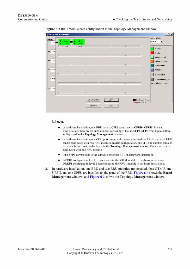
Figure 6-3 RRU module data configuration in the Topology Management window
NOTE
l In hardware installation, one BBU has six CPRI ports, that is, CPRI0–CPRI5. In dataconfiguration, there are six link numbers accordingly, that is, SFP0–SFP5 from top to bottom,as displayed in the Topology Management window.
l In hardware installation, one CPRI port can provide connections to three RRUs, and each RRUcan be configured with two RRU modules. In data configuration, one SFP link number containssix levels from 1 to 6, as displayed in the Topology Management window. Each level can beconfigured with one RRU module.
l Link SFP0 corresponds to the CPRI0 port of the BBU in hardware installation.
l DRRU0 configured in level 1 corresponds to the RRU0 module in hardware installation.DRRU1 configured in level 2 corresponds to the RRU1 module in hardware installation.
2. In hardware installation, one BBU and two RRU modules are installed. One GTMU, oneUBFU, and one UPEU are installed on the panel of the BBU. Figure 6-4 shows the BoardManagement window, and Figure 6-3 shows the Topology Management window.
DBS3900 GSMCommissioning Guide 6 Checking the Transmission and Networking
Issue 04 (2008-09-05) Huawei Proprietary and ConfidentialCopyright © Huawei Technologies Co., Ltd
6-7
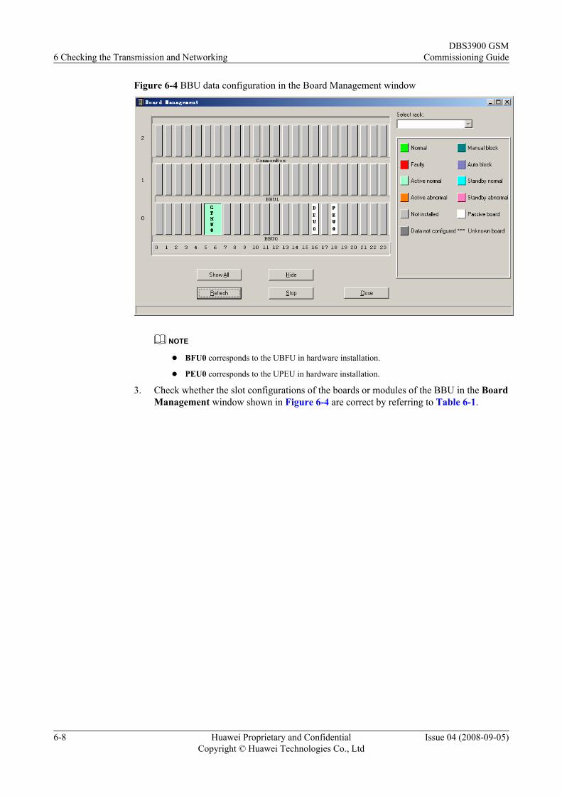
Figure 6-4 BBU data configuration in the Board Management window
NOTE
l BFU0 corresponds to the UBFU in hardware installation.
l PEU0 corresponds to the UPEU in hardware installation.
3. Check whether the slot configurations of the boards or modules of the BBU in the BoardManagement window shown in Figure 6-4 are correct by referring to Table 6-1.
6 Checking the Transmission and NetworkingDBS3900 GSM
Commissioning Guide
6-8 Huawei Proprietary and ConfidentialCopyright © Huawei Technologies Co., Ltd
Issue 04 (2008-09-05)
7 Commission the Antenna System
About This Chapter
This describes how to commission the antenna system. You must check whether the antenna isconnected properly and whether the Voltage Standing-Wave Ratio (VSWR) is normal. If anRET antenna is configured, you must commission the RET antenna.
7.1 Measuring the VSWR at the Antenna PortThis describes how to check the VSWR at the antenna port. If the VSWR at the antenna port isless than or equal to 1.5, you can infer that the transmission of the antenna system is normal.The Site Master is taken as an example to describe the procedure for measuring the VSWR.
7.2 Checking the Antenna ConnectionThis describes how to check whether the feeders are misconnected by using a drive tester orthrough a dialing test. If an RET antenna is configured, check whether the cables of the RETantenna are connected properly.
7.3 Measuring the Output Power of the TRXThis describes how to obtain the output power of the TRX, which indicates the operation statusof the DBS3900. You need to check the output power of only the TRX that transmits power onall timeslots.
DBS3900 GSMCommissioning Guide 7 Commission the Antenna System
Issue 04 (2008-09-05) Huawei Proprietary and ConfidentialCopyright © Huawei Technologies Co., Ltd
7-1
7.1 Measuring the VSWR at the Antenna PortThis describes how to check the VSWR at the antenna port. If the VSWR at the antenna port isless than or equal to 1.5, you can infer that the transmission of the antenna system is normal.The Site Master is taken as an example to describe the procedure for measuring the VSWR.
PrerequisiteThe BTS is powered off.
NOTE
If you have checked the VSWR before powering on the BTS, you do not need to perform this task.
Procedure
Step 1 Measure the VSWR at the antenna port by using the Site Master.
If... Then...
The VSWR is less than or equal to 1.5, You can infer that the transmission of the antennasystem is normal. Record the measured value in theData Sheet for Commissioning.
The VSWR is greater than 1.5, You can infer that the transmission of the antennasystem is not normal. Go to Step 2.
Step 2 Locate the fault on the jumper or feeder where the VSWR is not normal by using the Site Master.Check whether the jumper or feeder is securely connected and whether the connectors are ingood condition. If any connector is damaged, replace it.
NOTE
The fault often occurs on the connectors between the jumper and the feeder or the connectors between thejumper and the antenna.
----End
7.2 Checking the Antenna ConnectionThis describes how to check whether the feeders are misconnected by using a drive tester orthrough a dialing test. If an RET antenna is configured, check whether the cables of the RETantenna are connected properly.
7.2.1 Checking the Antenna Connection with an MSThis describes how to check the antenna connections with an MS. You can lock the MS on acell frequency and perform the dialing test. Then, you can determine the antenna connectionconditions by checking whether the dialing test is successful.
7.2.2 Checking the Antenna Connection by Using a Drive TesterThis describes how to check the antenna connections by using a drive tester. You can determinethe antenna connection conditions by checking whether the frequencies of the BCCH and BSIC
7 Commission the Antenna SystemDBS3900 GSM
Commissioning Guide
7-2 Huawei Proprietary and ConfidentialCopyright © Huawei Technologies Co., Ltd
Issue 04 (2008-09-05)
in the configuration data are consistent with the actual frequencies and whether the test level isnormal.
7.2.1 Checking the Antenna Connection with an MSThis describes how to check the antenna connections with an MS. You can lock the MS on acell frequency and perform the dialing test. Then, you can determine the antenna connectionconditions by checking whether the dialing test is successful.
Prerequisitel The BTS is powered on and is working normally.
l The antenna system is connected to the BTS cabinet.
l The test MS is registered with the HLR.
Procedure
Step 1 Power on the test MS and check the process of the MS in searching the GSM network.
If... Then...
The test MS fails to find the network, l Check whether the test MS has a SIM card. If thetest MS does not have a SIM card, insert the SIMcard in the MS.
l Check whether the SIM card supportsauthentication and encryption. If the SIM carddoes not support authentication and encryption,replace the SIM card.
l Check whether the test MS is functional. If the testMS is faulty, replace it.
The test MS finds the network, Go to Step 2.
Step 2 Lock the test MS to a frequency of a logical cell covered by the BTS.
Step 3 Perform the dialing test using the test MS. Then, check whether the antenna corresponding tothe frequency is connected properly according to the test results.
If... Then...
The dialing test succeeds, You can infer that the feeder corresponding to the frequency isconnected properly. Go to Step 4.
The dialing test fails, You can infer that the feeder corresponding to the frequency maybe connected improperly. Check the connections of the feeder andmake adjustment accordingly..
DBS3900 GSMCommissioning Guide 7 Commission the Antenna System
Issue 04 (2008-09-05) Huawei Proprietary and ConfidentialCopyright © Huawei Technologies Co., Ltd
7-3
NOTE
To ensure the accuracy of test results, do as follows:
l Make test calls within the power range of less than –30 dBm to -70 dBm under the tower.
l Perform the dialing test for more than five times.
Step 4 Repeat Step 2 through Step 3 to check the antennas on all the frequencies of the BTS areconnected properly.
----End
7.2.2 Checking the Antenna Connection by Using a Drive TesterThis describes how to check the antenna connections by using a drive tester. You can determinethe antenna connection conditions by checking whether the frequencies of the BCCH and BSICin the configuration data are consistent with the actual frequencies and whether the test level isnormal.
Prerequisite
A drive tester and a test MS are available.
Procedure
Step 1 Record the longitude and latitude of the BTS in the drive test map.
Step 2 Start the drive test in the direction of the main lobe of the antenna in the target cell.
Step 3 Record the actual frequencies of the BCCH and BSIC in the cell. Compare the records with thosein configuration data of the BTS to ensure consistency.
Step 4 Check whether the test level is normal. The normal test level ranges from –48 dBm to –96 dBm.
CAUTIONAfter the drive test is complete, back up the BTS data configuration file.
----End
7.3 Measuring the Output Power of the TRXThis describes how to obtain the output power of the TRX, which indicates the operation statusof the DBS3900. You need to check the output power of only the TRX that transmits power onall timeslots.
Prerequisite
The BTS is powered on.
7 Commission the Antenna SystemDBS3900 GSM
Commissioning Guide
7-4 Huawei Proprietary and ConfidentialCopyright © Huawei Technologies Co., Ltd
Issue 04 (2008-09-05)
Procedure
Step 1 Measure the output power of the TRX at the TX port of the RRU module by using a power meter.
Step 2 Check whether the output power of the TRX is within the normal range.
NOTE
For example, in 900 MHz no combination mode, if the normal power is set to 30 W (44.7 dBm), the normalrange of the output power on the TX port of the RRU module is 44.7 ± 1 dBm.
If… Then…
The output power is within the normalrange,
Record the value of the power in the Data Sheetfor Commissioning.
The output power is beyond the normalrange,
1. Check whether the cable of the power meter isconnected securely.
2. Check whether the parameters of the powermeter are set properly and whether the powermeter is calibrated.
3. Check whether the RRU module is configuredproperly and can output power.
4. Replace the RRU module in which the outputpower of the TRX is abnormal.
Step 3 Repeat Step 1 through Step 2 to check the output power of all the TRXs.
----End
DBS3900 GSMCommissioning Guide 7 Commission the Antenna System
Issue 04 (2008-09-05) Huawei Proprietary and ConfidentialCopyright © Huawei Technologies Co., Ltd
7-5

8 Checking the operating status of theDBS3900
About This Chapter
This describes how to check the operation status of the DBS3900. To ensure the normal operationof the DBS3900, you need to check its operating status and rectify the faults accordingly. Theprocedure of checking the operation status of the DBS3900 involves checking the status of LEDs,checking the alarm information of the DBS3900, and performing the board loopback test.
Prerequisitel The transmission between the BBU and the RRU and the transmission between the BBU
and the BSC are normal.l The actual networking is consistent with the data configuration.
l The antenna system is commissioned, and each parameter is configured in accordance withthe actual requirements.
8.1 Checking the Status of the DBS3900 LEDsThis describes how to check the status of the LEDs, which indicate the operating status of theboards and modules of the DBS3900. You must check the LEDs on the RRU module, on theUBFU, on the UPEU, and on the GTMU.
8.2 Checking the Alarm Information of the DBS3900This describes how to check the alarm information of the DBS3900 on the Site MaintenanceTerminal System. If the alarm information of the DBS3900 exists, rectify the fault according tothe suggestions given on the Site Maintenance Terminal System.
8.3 Performing the Loopback TestThis describes how to perform the loopback test. The GTMU loopback test is performed to testthe link between the Site Maintenance Terminal System and the GTMU. The RRU loopbacktest is performed to test the logic channel A or B of the RRU module.
DBS3900 GSMCommissioning Guide 8 Checking the operating status of the DBS3900
Issue 04 (2008-09-05) Huawei Proprietary and ConfidentialCopyright © Huawei Technologies Co., Ltd
8-1
8.1 Checking the Status of the DBS3900 LEDsThis describes how to check the status of the LEDs, which indicate the operating status of theboards and modules of the DBS3900. You must check the LEDs on the RRU module, on theUBFU, on the UPEU, and on the GTMU.
Prerequisite
The output power of the TRXs in the RRU module is normal.
Procedure
Step 1 Check whether the status of the LEDs on the boards and modules of the BBU is normal.
1. Check the status of the LEDs on the UBFU.
2. Check the status of the LEDs on the UPEU.
3. Check the status of the LEDs on the GTMU.
Step 2 Check whether the status of the LEDs on the RRU Module is normal.
Step 3 If any LED is abnormal, perform the steps given in Checking the Alarm Information of theDBS3900.
----End
8.2 Checking the Alarm Information of the DBS3900This describes how to check the alarm information of the DBS3900 on the Site MaintenanceTerminal System. If the alarm information of the DBS3900 exists, rectify the fault according tothe suggestions given on the Site Maintenance Terminal System.
Procedure
Step 1 Confirm the board or module type, and then check the alarm information on the Site MaintenanceTerminal System.
If… Then…
The board or module type is UBFU, Query the alarm information by referring toBBU Board Alarm.
The board or module type is UPEU, Query the alarm information by referring toBBU Board Alarm.
The board or module type is GTMU, Query the alarm information by referring toBBU Board Alarm.
8 Checking the operating status of the DBS3900DBS3900 GSM
Commissioning Guide
8-2 Huawei Proprietary and ConfidentialCopyright © Huawei Technologies Co., Ltd
Issue 04 (2008-09-05)
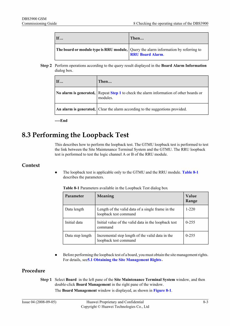
If… Then…
The board or module type is RRU module, Query the alarm information by referring toRRU Board Alarm.
Step 2 Perform operations according to the query result displayed in the Board Alarm Informationdialog box.
If… Then…
No alarm is generated, Repeat Step 1 to check the alarm information of other boards ormodules.
An alarm is generated, Clear the alarm according to the suggestions provided.
----End
8.3 Performing the Loopback TestThis describes how to perform the loopback test. The GTMU loopback test is performed to testthe link between the Site Maintenance Terminal System and the GTMU. The RRU loopbacktest is performed to test the logic channel A or B of the RRU module.
Contextl The loopback test is applicable only to the GTMU and the RRU module. Table 8-1
describes the parameters.
Table 8-1 Parameters available in the Loopback Test dialog box
Parameter Meaning ValueRange
Data length Length of the valid data of a single frame in theloopback test command
1-220
Initial data Initial value of the valid data in the loopback testcommand
0-255
Data step length Incremental step length of the valid data in theloopback test command
0-255
l Before performing the loopback test of a board, you must obtain the site management rights.
For details, see5.1 Obtaining the Site Management Rights。
ProcedureStep 1 Select Board in the left pane of the Site Maintenance Terminal System window, and then
double-click Board Management in the right pane of the window.The Board Management window is displayed, as shown in Figure 8-1.
DBS3900 GSMCommissioning Guide 8 Checking the operating status of the DBS3900
Issue 04 (2008-09-05) Huawei Proprietary and ConfidentialCopyright © Huawei Technologies Co., Ltd
8-3
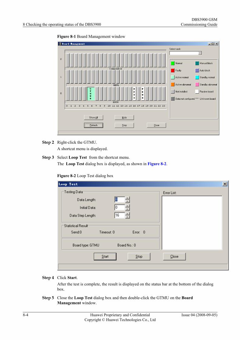
Figure 8-1 Board Management window
Step 2 Right-click the GTMU.A shortcut menu is displayed.
Step 3 Select Loop Test from the shortcut menu.The Loop Test dialog box is displayed, as shown in Figure 8-2.
Figure 8-2 Loop Test dialog box
Step 4 Click Start.After the test is complete, the result is displayed on the status bar at the bottom of the dialogbox.
Step 5 Close the Loop Test dialog box and then double-click the GTMU on the BoardManagement window.
8 Checking the operating status of the DBS3900DBS3900 GSM
Commissioning Guide
8-4 Huawei Proprietary and ConfidentialCopyright © Huawei Technologies Co., Ltd
Issue 04 (2008-09-05)
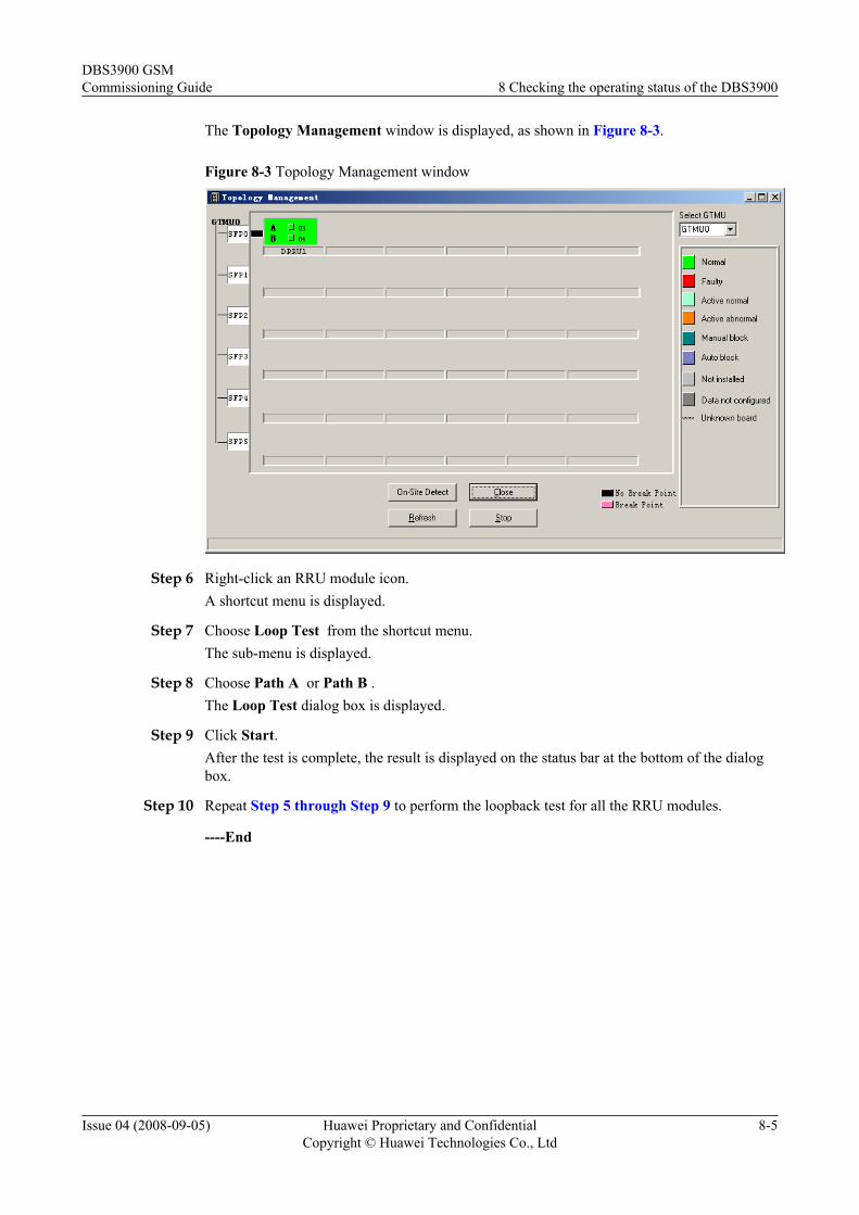
The Topology Management window is displayed, as shown in Figure 8-3.
Figure 8-3 Topology Management window
Step 6 Right-click an RRU module icon.A shortcut menu is displayed.
Step 7 Choose Loop Test from the shortcut menu.The sub-menu is displayed.
Step 8 Choose Path A or Path B .The Loop Test dialog box is displayed.
Step 9 Click Start.After the test is complete, the result is displayed on the status bar at the bottom of the dialogbox.
Step 10 Repeat Step 5 through Step 9 to perform the loopback test for all the RRU modules.
----End
DBS3900 GSMCommissioning Guide 8 Checking the operating status of the DBS3900
Issue 04 (2008-09-05) Huawei Proprietary and ConfidentialCopyright © Huawei Technologies Co., Ltd
8-5

9 Testing the DBS3900 Services
About This Chapter
This describes how to test the DBS3900 services by using a test MS. The DBS3900 servicesconsist of the circuit switched (CS) services and the packet switched (PS) services.
PrerequisiteThe DBS3900 is in normal operation.
9.1 Performing the Loopback Test of a ChannelThis describes how to perform the loopback test of a channel. Before testing the CS and PSservices, you must check whether the transmission links of the signaling channel and trafficchannel are normal. The loopback test of a channel consists of the loopback test of a signalingchannel and the loopback test of a traffic channel.
9.2 Testing CS ServicesThis describes how to test CS services by making test calls between MSs or between an MS anda PSTN user.
9.3 Testing PS ServicesThis describes how to test PS services by browsing websites and downloading files through anMS. You need to test only the BTS that is configured with the GPRS or EGPRS services.
DBS3900 GSMCommissioning Guide 9 Testing the DBS3900 Services
Issue 04 (2008-09-05) Huawei Proprietary and ConfidentialCopyright © Huawei Technologies Co., Ltd
9-1
9.1 Performing the Loopback Test of a ChannelThis describes how to perform the loopback test of a channel. Before testing the CS and PSservices, you must check whether the transmission links of the signaling channel and trafficchannel are normal. The loopback test of a channel consists of the loopback test of a signalingchannel and the loopback test of a traffic channel.
9.1.1 Performing the Loopback Test of a Signaling ChannelThis describes how to perform the loopback test of a signaling channel. Before testing the CSand PS services, you must check whether the transmission links of the signaling channel arenormal through the baseband test on the Site Maintenance Terminal System. The baseband testconsists of the BIU loopback test and the TRX self-test.
9.1.2 Performing the Loopback Test of a Traffic ChannelThis describes how to perform the loopback test of a traffic channel. Before testing the circuitswitched (CS) and packet switched (PS) services, you need to perform the loopback test on theSite Maintenance Terminal System to check the transmission link of traffic channels of the BTS.The loopback test of a traffic channel involves the BIU loopback test and the TRX RF self-test.
9.1.1 Performing the Loopback Test of a Signaling ChannelThis describes how to perform the loopback test of a signaling channel. Before testing the CSand PS services, you must check whether the transmission links of the signaling channel arenormal through the baseband test on the Site Maintenance Terminal System. The baseband testconsists of the BIU loopback test and the TRX self-test.
Background Introductionl The BIU loopback test is performed to test the link transmission of the TRX timeslots on
the DBUS.l The TRX self-test is performed to check whether the logical channel from the BBU to the
DSP in the RRU/DRFU is functional.l Before performing the loopback test of a signaling channel, you must obtain the site
management rights. For details, see5.1 Obtaining the Site Management Rights。
Procedure
Step 1 In the left pane of the Site Maintenance Terminal System window, select BT. In the right paneof the window, double-click BT Loop Test.The BT Loop Test dialog box is displayed, as shown in Figure 9-1.
9 Testing the DBS3900 ServicesDBS3900 GSM
Commissioning Guide
9-2 Huawei Proprietary and ConfidentialCopyright © Huawei Technologies Co., Ltd
Issue 04 (2008-09-05)
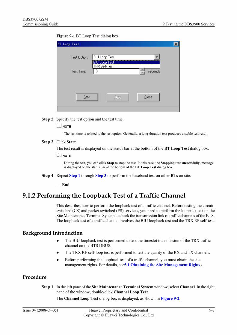
Figure 9-1 BT Loop Test dialog box
Step 2 Specify the test option and the test time.
NOTE
The test time is related to the test option. Generally, a long-duration test produces a stable test result.
Step 3 Click Start.The test result is displayed on the status bar at the bottom of the BT Loop Test dialog box.
NOTE
During the test, you can click Stop to stop the test. In this case, the Stopping test successfully. messageis displayed on the status bar at the bottom of the BT Loop Test dialog box.
Step 4 Repeat Step 1 through Step 3 to perform the baseband test on other BTs on site.
----End
9.1.2 Performing the Loopback Test of a Traffic ChannelThis describes how to perform the loopback test of a traffic channel. Before testing the circuitswitched (CS) and packet switched (PS) services, you need to perform the loopback test on theSite Maintenance Terminal System to check the transmission link of traffic channels of the BTS.The loopback test of a traffic channel involves the BIU loopback test and the TRX RF self-test.
Background Introductionl The BIU loopback test is performed to test the timeslot transmission of the TRX traffic
channel on the BTS DBUS.
l The TRX RF self-loop test is performed to test the quality of the RX and TX channels.
l Before performing the loopback test of a traffic channel, you must obtain the sitemanagement rights. For details, see5.1 Obtaining the Site Management Rights。
Procedure
Step 1 In the left pane of the Site Maintenance Terminal System window, select Channel. In the rightpane of the window, double-click Channel Loop Test.The Channel Loop Test dialog box is displayed, as shown in Figure 9-2.
DBS3900 GSMCommissioning Guide 9 Testing the DBS3900 Services
Issue 04 (2008-09-05) Huawei Proprietary and ConfidentialCopyright © Huawei Technologies Co., Ltd
9-3
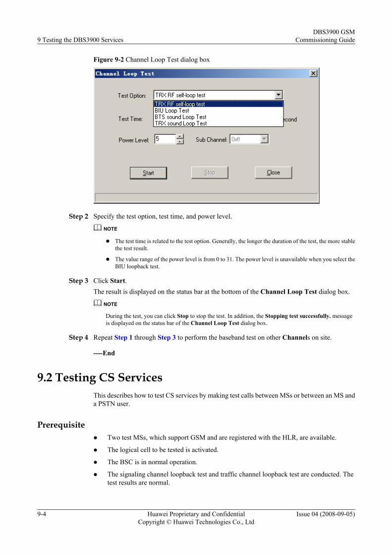
Figure 9-2 Channel Loop Test dialog box
Step 2 Specify the test option, test time, and power level.
NOTE
l The test time is related to the test option. Generally, the longer the duration of the test, the more stablethe test result.
l The value range of the power level is from 0 to 31. The power level is unavailable when you select theBIU loopback test.
Step 3 Click Start.The result is displayed on the status bar at the bottom of the Channel Loop Test dialog box.
NOTE
During the test, you can click Stop to stop the test. In addition, the Stopping test successfully. messageis displayed on the status bar of the Channel Loop Test dialog box.
Step 4 Repeat Step 1 through Step 3 to perform the baseband test on other Channels on site.
----End
9.2 Testing CS ServicesThis describes how to test CS services by making test calls between MSs or between an MS anda PSTN user.
Prerequisitel Two test MSs, which support GSM and are registered with the HLR, are available.
l The logical cell to be tested is activated.
l The BSC is in normal operation.
l The signaling channel loopback test and traffic channel loopback test are conducted. Thetest results are normal.
9 Testing the DBS3900 ServicesDBS3900 GSM
Commissioning Guide
9-4 Huawei Proprietary and ConfidentialCopyright © Huawei Technologies Co., Ltd
Issue 04 (2008-09-05)
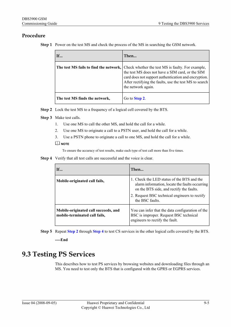
Procedure
Step 1 Power on the test MS and check the process of the MS in searching the GSM network.
If... Then...
The test MS fails to find the network, Check whether the test MS is faulty. For example,the test MS does not have a SIM card, or the SIMcard does not support authentication and encryption.After rectifying the faults, use the test MS to searchthe network again.
The test MS finds the network, Go to Step 2.
Step 2 Lock the test MS to a frequency of a logical cell covered by the BTS.
Step 3 Make test calls.1. Use one MS to call the other MS, and hold the call for a while.2. Use one MS to originate a call to a PSTN user, and hold the call for a while.3. Use a PSTN phone to originate a call to one MS, and hold the call for a while.
NOTE
To ensure the accuracy of test results, make each type of test call more than five times.
Step 4 Verify that all test calls are successful and the voice is clear.
If... Then...
Mobile-originated call fails, 1. Check the LED status of the BTS and thealarm information, locate the faults occurringon the BTS side, and rectify the faults.
2. Request BSC technical engineers to rectifythe BSC faults.
Mobile-originated call succeeds, andmobile-terminated call fails,
You can infer that the data configuration of theBSC is improper. Request BSC technicalengineers to rectify the fault.
Step 5 Repeat Step 2 through Step 4 to test CS services in the other logical cells covered by the BTS.
----End
9.3 Testing PS ServicesThis describes how to test PS services by browsing websites and downloading files through anMS. You need to test only the BTS that is configured with the GPRS or EGPRS services.
DBS3900 GSMCommissioning Guide 9 Testing the DBS3900 Services
Issue 04 (2008-09-05) Huawei Proprietary and ConfidentialCopyright © Huawei Technologies Co., Ltd
9-5
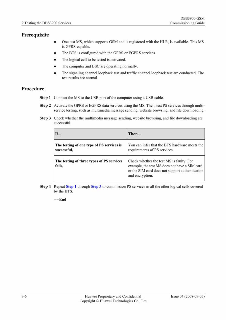
Prerequisitel One test MS, which supports GSM and is registered with the HLR, is available. This MS
is GPRS-capable.l The BTS is configured with the GPRS or EGPRS services.
l The logical cell to be tested is activated.
l The computer and BSC are operating normally.
l The signaling channel loopback test and traffic channel loopback test are conducted. Thetest results are normal.
Procedure
Step 1 Connect the MS to the USB port of the computer using a USB cable.
Step 2 Activate the GPRS or EGPRS data services using the MS. Then, test PS services through multi-service testing, such as multimedia message sending, website browsing, and file downloading.
Step 3 Check whether the multimedia message sending, website browsing, and file downloading aresuccessful.
If... Then...
The testing of one type of PS services issuccessful,
You can infer that the BTS hardware meets therequirements of PS services.
The testing of three types of PS servicesfails,
Check whether the test MS is faulty. Forexample, the test MS does not have a SIM card,or the SIM card does not support authenticationand encryption.
Step 4 Repeat Step 1 through Step 3 to commission PS services in all the other logical cells coveredby the BTS.
----End
9 Testing the DBS3900 ServicesDBS3900 GSM
Commissioning Guide
9-6 Huawei Proprietary and ConfidentialCopyright © Huawei Technologies Co., Ltd
Issue 04 (2008-09-05)
10 Monitoring the Environment for theDBS3900
About This Chapter
This describes the various environment alarms of the DBS3900. It also describes how to performenvironment monitoring for the DBS3900.
10.1 BTS Environment Alarm TypesThis describes the various types of environment alarms of the BTS. The alarms consist of thefire alarm, smoke alarm, infrared alarm, water alarm, temperature alarm, humidity alarm, air-conditioner alarm, door status alarm, and burglar alarm.
10.2 Monitoring EnvironmentThis function is performed to monitor and manage the environment parameters in a site. Byperforming this function, you can view the current temperature and humidity and set thetemperature and humidity thresholds. The BTS can run normally in a safe and suitable siteenvironment. You can also clear a burglar alarm or a smoke alarm and disable an EAC alarm.
DBS3900 GSMCommissioning Guide 10 Monitoring the Environment for the DBS3900
Issue 04 (2008-09-05) Huawei Proprietary and ConfidentialCopyright © Huawei Technologies Co., Ltd
10-1
10.1 BTS Environment Alarm TypesThis describes the various types of environment alarms of the BTS. The alarms consist of thefire alarm, smoke alarm, infrared alarm, water alarm, temperature alarm, humidity alarm, air-conditioner alarm, door status alarm, and burglar alarm.
NOTE
l Critical alarm: devices or resources may be unusable, and restoration should be performed at once.
l Major alarm: The QoS of devices or resources severely deteriorates, and measures should be taken assoon as possible.
l The thresholds of temperature alarm and humidity alarm are subject to the local climate and terrainconditions and should be specified on the basis of the field requirements.
Fire AlarmThe fire alarm is the environment alarm generated when the equipment room is on fire. This isa critical alarm.
Smoke AlarmThe smoke alarm is an environment alarm generated when the smoke density in the equipmentroom reaches a predefined threshold. This is a critical alarm.
Infrared AlarmThe infrared alarm is an environment alarm generated when an infrared facility is taken into theequipment room or is in the infrared detection range of the cabinet. This is a major alarm.
Water AlarmThe water alarm is an environment alarm generated when water immersion occurs in theequipment room. This is a major alarm.
Temperature AlarmThe temperature alarm consists of the overtemperature alarm and the undertemperature alarm.This is a major alarm.
l The overtemperature alarm is generated when the ambient temperature is higher than thepredefined upper threshold of the temperature.
l The undertemperature alarm is generated when the ambient temperature is lower than thepredefined lower threshold of the temperature.
Humidity AlarmThe humidity alarm consists of the high humidity alarm and the low humidity alarm. This is amajor alarm.
l The high humidity alarm is generated when the environment humidity is higher than thepredefined upper threshold of the humidity.
10 Monitoring the Environment for the DBS3900DBS3900 GSM
Commissioning Guide
10-2 Huawei Proprietary and ConfidentialCopyright © Huawei Technologies Co., Ltd
Issue 04 (2008-09-05)
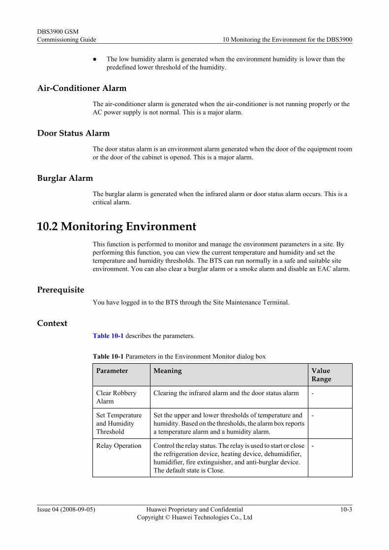
l The low humidity alarm is generated when the environment humidity is lower than thepredefined lower threshold of the humidity.
Air-Conditioner Alarm
The air-conditioner alarm is generated when the air-conditioner is not running properly or theAC power supply is not normal. This is a major alarm.
Door Status Alarm
The door status alarm is an environment alarm generated when the door of the equipment roomor the door of the cabinet is opened. This is a major alarm.
Burglar Alarm
The burglar alarm is generated when the infrared alarm or door status alarm occurs. This is acritical alarm.
10.2 Monitoring EnvironmentThis function is performed to monitor and manage the environment parameters in a site. Byperforming this function, you can view the current temperature and humidity and set thetemperature and humidity thresholds. The BTS can run normally in a safe and suitable siteenvironment. You can also clear a burglar alarm or a smoke alarm and disable an EAC alarm.
PrerequisiteYou have logged in to the BTS through the Site Maintenance Terminal.
ContextTable 10-1 describes the parameters.
Table 10-1 Parameters in the Environment Monitor dialog box
Parameter Meaning ValueRange
Clear RobberyAlarm
Clearing the infrared alarm and the door status alarm -
Set Temperatureand HumidityThreshold
Set the upper and lower thresholds of temperature andhumidity. Based on the thresholds, the alarm box reportsa temperature alarm and a humidity alarm.
-
Relay Operation Control the relay status. The relay is used to start or closethe refrigeration device, heating device, dehumidifier,humidifier, fire extinguisher, and anti-burglar device.The default state is Close.
-
DBS3900 GSMCommissioning Guide 10 Monitoring the Environment for the DBS3900
Issue 04 (2008-09-05) Huawei Proprietary and ConfidentialCopyright © Huawei Technologies Co., Ltd
10-3
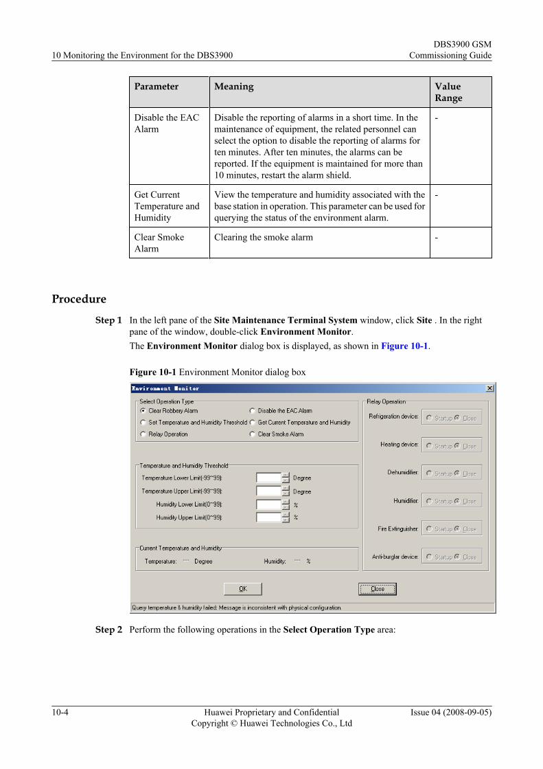
Parameter Meaning ValueRange
Disable the EACAlarm
Disable the reporting of alarms in a short time. In themaintenance of equipment, the related personnel canselect the option to disable the reporting of alarms forten minutes. After ten minutes, the alarms can bereported. If the equipment is maintained for more than10 minutes, restart the alarm shield.
-
Get CurrentTemperature andHumidity
View the temperature and humidity associated with thebase station in operation. This parameter can be used forquerying the status of the environment alarm.
-
Clear SmokeAlarm
Clearing the smoke alarm -
Procedure
Step 1 In the left pane of the Site Maintenance Terminal System window, click Site . In the rightpane of the window, double-click Environment Monitor.The Environment Monitor dialog box is displayed, as shown in Figure 10-1.
Figure 10-1 Environment Monitor dialog box
Step 2 Perform the following operations in the Select Operation Type area:
10 Monitoring the Environment for the DBS3900DBS3900 GSM
Commissioning Guide
10-4 Huawei Proprietary and ConfidentialCopyright © Huawei Technologies Co., Ltd
Issue 04 (2008-09-05)
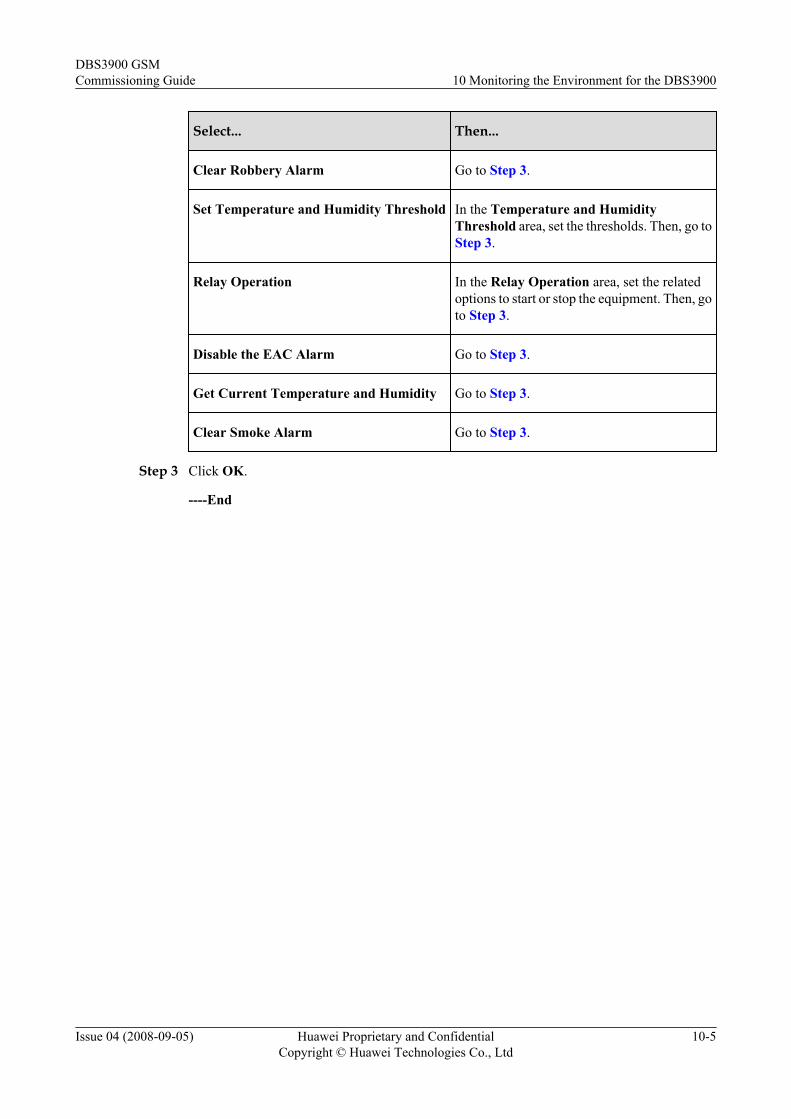
Select... Then...
Clear Robbery Alarm Go to Step 3.
Set Temperature and Humidity Threshold In the Temperature and HumidityThreshold area, set the thresholds. Then, go toStep 3.
Relay Operation In the Relay Operation area, set the relatedoptions to start or stop the equipment. Then, goto Step 3.
Disable the EAC Alarm Go to Step 3.
Get Current Temperature and Humidity Go to Step 3.
Clear Smoke Alarm Go to Step 3.
Step 3 Click OK.
----End
DBS3900 GSMCommissioning Guide 10 Monitoring the Environment for the DBS3900
Issue 04 (2008-09-05) Huawei Proprietary and ConfidentialCopyright © Huawei Technologies Co., Ltd
10-5

11 FAQs for BTS Commissioning
About This Chapter
This describes the fault symptoms and cause analysis in the BTS commissioning.
11.1 Failed Communication Between the Site Maintenance Terminal and the BTSThis describes the fault symptom and analyzes the cause of the failed communication betweenthe Site Maintenance Terminal and the BTS. It also provides the fault handling suggestions.
11.2 Faulty E1 LinkThis describes the fault symptom and analyzes the cause of the faulty E1 link. It also providesthe fault handling suggestions.
11.3 Failure of an MS to Search the NetworkThis describes the fault symptom and analyzes the cause of the failure of an MS to search thenetwork.
11.4 Service Dialing FailureThis describes the fault symptom and analyzes the cause of the service dialing failure. It alsoprovides the fault handling suggestions.
11.5 Low GRPS Data Transmission RateThis describes the fault symptom and analyzes the cause of low GPRS data transmission rate.
DBS3900 GSMCommissioning Guide 11 FAQs for BTS Commissioning
Issue 04 (2008-09-05) Huawei Proprietary and ConfidentialCopyright © Huawei Technologies Co., Ltd
11-1
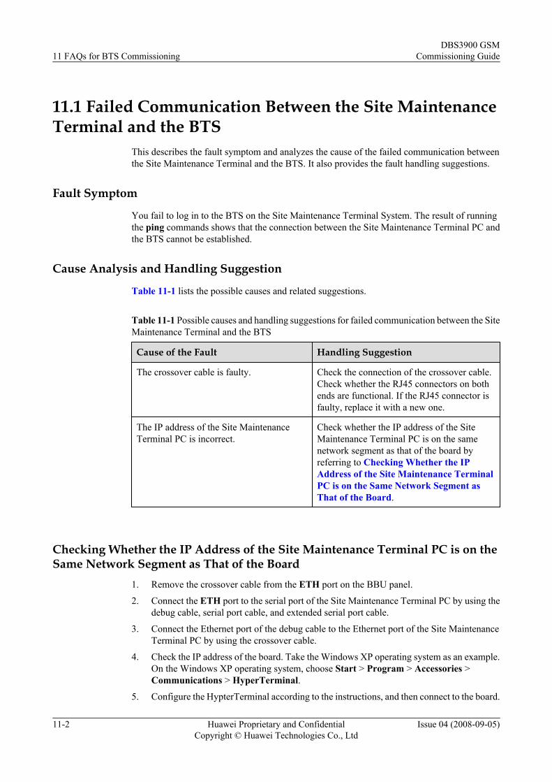
11.1 Failed Communication Between the Site MaintenanceTerminal and the BTS
This describes the fault symptom and analyzes the cause of the failed communication betweenthe Site Maintenance Terminal and the BTS. It also provides the fault handling suggestions.
Fault Symptom
You fail to log in to the BTS on the Site Maintenance Terminal System. The result of runningthe ping commands shows that the connection between the Site Maintenance Terminal PC andthe BTS cannot be established.
Cause Analysis and Handling Suggestion
Table 11-1 lists the possible causes and related suggestions.
Table 11-1 Possible causes and handling suggestions for failed communication between the SiteMaintenance Terminal and the BTS
Cause of the Fault Handling Suggestion
The crossover cable is faulty. Check the connection of the crossover cable.Check whether the RJ45 connectors on bothends are functional. If the RJ45 connector isfaulty, replace it with a new one.
The IP address of the Site MaintenanceTerminal PC is incorrect.
Check whether the IP address of the SiteMaintenance Terminal PC is on the samenetwork segment as that of the board byreferring to Checking Whether the IPAddress of the Site Maintenance TerminalPC is on the Same Network Segment asThat of the Board.
Checking Whether the IP Address of the Site Maintenance Terminal PC is on theSame Network Segment as That of the Board
1. Remove the crossover cable from the ETH port on the BBU panel.
2. Connect the ETH port to the serial port of the Site Maintenance Terminal PC by using thedebug cable, serial port cable, and extended serial port cable.
3. Connect the Ethernet port of the debug cable to the Ethernet port of the Site MaintenanceTerminal PC by using the crossover cable.
4. Check the IP address of the board. Take the Windows XP operating system as an example.On the Windows XP operating system, choose Start > Program > Accessories >Communications > HyperTerminal.
5. Configure the HypterTerminal according to the instructions, and then connect to the board.
11 FAQs for BTS CommissioningDBS3900 GSM
Commissioning Guide
11-2 Huawei Proprietary and ConfidentialCopyright © Huawei Technologies Co., Ltd
Issue 04 (2008-09-05)
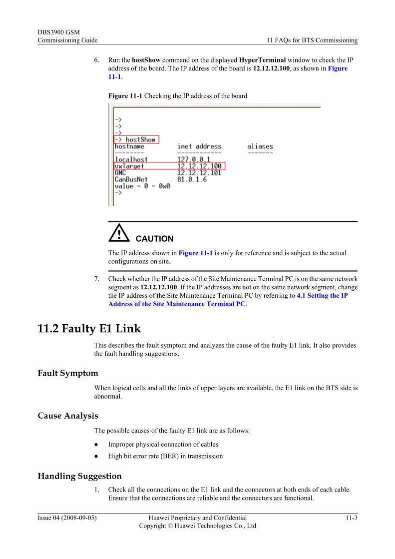
6. Run the hostShow command on the displayed HyperTerminal window to check the IPaddress of the board. The IP address of the board is 12.12.12.100, as shown in Figure11-1.
Figure 11-1 Checking the IP address of the board
CAUTIONThe IP address shown in Figure 11-1 is only for reference and is subject to the actualconfigurations on site.
7. Check whether the IP address of the Site Maintenance Terminal PC is on the same networksegment as 12.12.12.100. If the IP addresses are not on the same network segment, changethe IP address of the Site Maintenance Terminal PC by referring to 4.1 Setting the IPAddress of the Site Maintenance Terminal PC.
11.2 Faulty E1 LinkThis describes the fault symptom and analyzes the cause of the faulty E1 link. It also providesthe fault handling suggestions.
Fault SymptomWhen logical cells and all the links of upper layers are available, the E1 link on the BTS side isabnormal.
Cause AnalysisThe possible causes of the faulty E1 link are as follows:
l Improper physical connection of cables
l High bit error rate (BER) in transmission
Handling Suggestion1. Check all the connections on the E1 link and the connectors at both ends of each cable.
Ensure that the connections are reliable and the connectors are functional.
DBS3900 GSMCommissioning Guide 11 FAQs for BTS Commissioning
Issue 04 (2008-09-05) Huawei Proprietary and ConfidentialCopyright © Huawei Technologies Co., Ltd
11-3
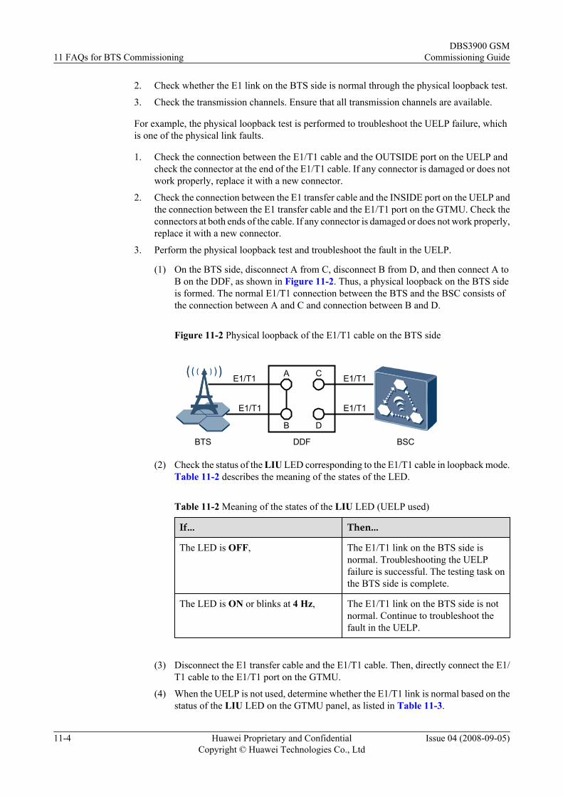
2. Check whether the E1 link on the BTS side is normal through the physical loopback test.
3. Check the transmission channels. Ensure that all transmission channels are available.
For example, the physical loopback test is performed to troubleshoot the UELP failure, whichis one of the physical link faults.
1. Check the connection between the E1/T1 cable and the OUTSIDE port on the UELP andcheck the connector at the end of the E1/T1 cable. If any connector is damaged or does notwork properly, replace it with a new connector.
2. Check the connection between the E1 transfer cable and the INSIDE port on the UELP andthe connection between the E1 transfer cable and the E1/T1 port on the GTMU. Check theconnectors at both ends of the cable. If any connector is damaged or does not work properly,replace it with a new connector.
3. Perform the physical loopback test and troubleshoot the fault in the UELP.
(1) On the BTS side, disconnect A from C, disconnect B from D, and then connect A toB on the DDF, as shown in Figure 11-2. Thus, a physical loopback on the BTS sideis formed. The normal E1/T1 connection between the BTS and the BSC consists ofthe connection between A and C and connection between B and D.
Figure 11-2 Physical loopback of the E1/T1 cable on the BTS side
A
B
C
D
BTS DDF BSC
E1/T1
E1/T1 E1/T1
E1/T1
(2) Check the status of the LIU LED corresponding to the E1/T1 cable in loopback mode.Table 11-2 describes the meaning of the states of the LED.
Table 11-2 Meaning of the states of the LIU LED (UELP used)
If... Then...
The LED is OFF, The E1/T1 link on the BTS side isnormal. Troubleshooting the UELPfailure is successful. The testing task onthe BTS side is complete.
The LED is ON or blinks at 4 Hz, The E1/T1 link on the BTS side is notnormal. Continue to troubleshoot thefault in the UELP.
(3) Disconnect the E1 transfer cable and the E1/T1 cable. Then, directly connect the E1/T1 cable to the E1/T1 port on the GTMU.
(4) When the UELP is not used, determine whether the E1/T1 link is normal based on thestatus of the LIU LED on the GTMU panel, as listed in Table 11-3.
11 FAQs for BTS CommissioningDBS3900 GSM
Commissioning Guide
11-4 Huawei Proprietary and ConfidentialCopyright © Huawei Technologies Co., Ltd
Issue 04 (2008-09-05)
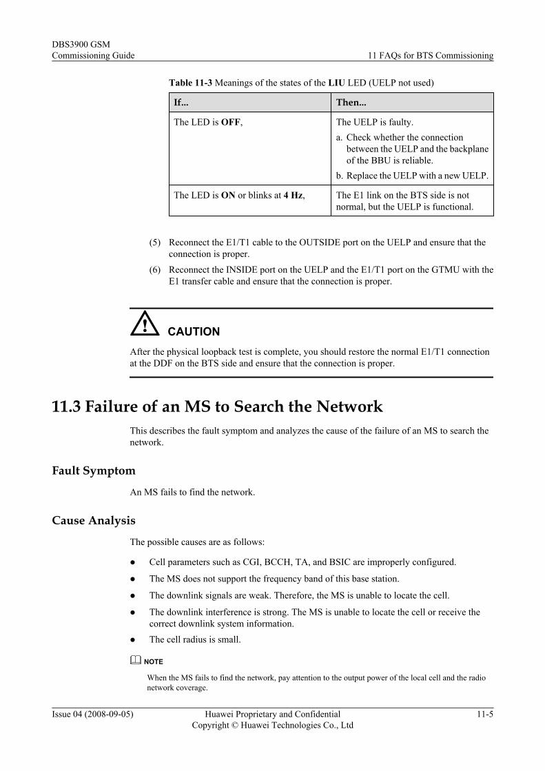
Table 11-3 Meanings of the states of the LIU LED (UELP not used)
If... Then...
The LED is OFF, The UELP is faulty.a. Check whether the connection
between the UELP and the backplaneof the BBU is reliable.
b. Replace the UELP with a new UELP.
The LED is ON or blinks at 4 Hz, The E1 link on the BTS side is notnormal, but the UELP is functional.
(5) Reconnect the E1/T1 cable to the OUTSIDE port on the UELP and ensure that the
connection is proper.(6) Reconnect the INSIDE port on the UELP and the E1/T1 port on the GTMU with the
E1 transfer cable and ensure that the connection is proper.
CAUTIONAfter the physical loopback test is complete, you should restore the normal E1/T1 connectionat the DDF on the BTS side and ensure that the connection is proper.
11.3 Failure of an MS to Search the NetworkThis describes the fault symptom and analyzes the cause of the failure of an MS to search thenetwork.
Fault Symptom
An MS fails to find the network.
Cause Analysis
The possible causes are as follows:
l Cell parameters such as CGI, BCCH, TA, and BSIC are improperly configured.
l The MS does not support the frequency band of this base station.
l The downlink signals are weak. Therefore, the MS is unable to locate the cell.
l The downlink interference is strong. The MS is unable to locate the cell or receive thecorrect downlink system information.
l The cell radius is small.
NOTE
When the MS fails to find the network, pay attention to the output power of the local cell and the radionetwork coverage.
DBS3900 GSMCommissioning Guide 11 FAQs for BTS Commissioning
Issue 04 (2008-09-05) Huawei Proprietary and ConfidentialCopyright © Huawei Technologies Co., Ltd
11-5
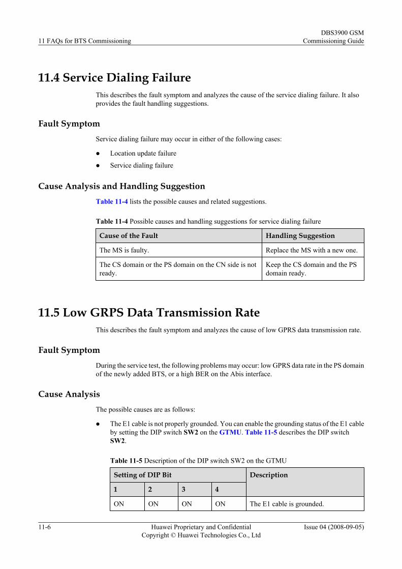
11.4 Service Dialing FailureThis describes the fault symptom and analyzes the cause of the service dialing failure. It alsoprovides the fault handling suggestions.
Fault SymptomService dialing failure may occur in either of the following cases:
l Location update failure
l Service dialing failure
Cause Analysis and Handling SuggestionTable 11-4 lists the possible causes and related suggestions.
Table 11-4 Possible causes and handling suggestions for service dialing failure
Cause of the Fault Handling Suggestion
The MS is faulty. Replace the MS with a new one.
The CS domain or the PS domain on the CN side is notready.
Keep the CS domain and the PSdomain ready.
11.5 Low GRPS Data Transmission RateThis describes the fault symptom and analyzes the cause of low GPRS data transmission rate.
Fault SymptomDuring the service test, the following problems may occur: low GPRS data rate in the PS domainof the newly added BTS, or a high BER on the Abis interface.
Cause AnalysisThe possible causes are as follows:
l The E1 cable is not properly grounded. You can enable the grounding status of the E1 cableby setting the DIP switch SW2 on the GTMU. Table 11-5 describes the DIP switchSW2.
Table 11-5 Description of the DIP switch SW2 on the GTMU
Setting of DIP Bit Description
1 2 3 4
ON ON ON ON The E1 cable is grounded.
11 FAQs for BTS CommissioningDBS3900 GSM
Commissioning Guide
11-6 Huawei Proprietary and ConfidentialCopyright © Huawei Technologies Co., Ltd
Issue 04 (2008-09-05)
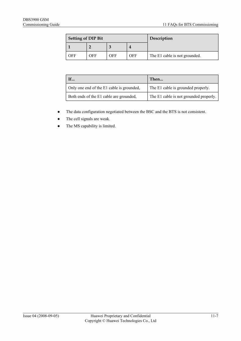
Setting of DIP Bit Description
1 2 3 4
OFF OFF OFF OFF The E1 cable is not grounded.
If... Then...
Only one end of the E1 cable is grounded, The E1 cable is grounded properly.
Both ends of the E1 cable are grounded, The E1 cable is not grounded properly.
l The data configuration negotiated between the BSC and the BTS is not consistent.
l The cell signals are weak.
l The MS capability is limited.
DBS3900 GSMCommissioning Guide 11 FAQs for BTS Commissioning
Issue 04 (2008-09-05) Huawei Proprietary and ConfidentialCopyright © Huawei Technologies Co., Ltd
11-7

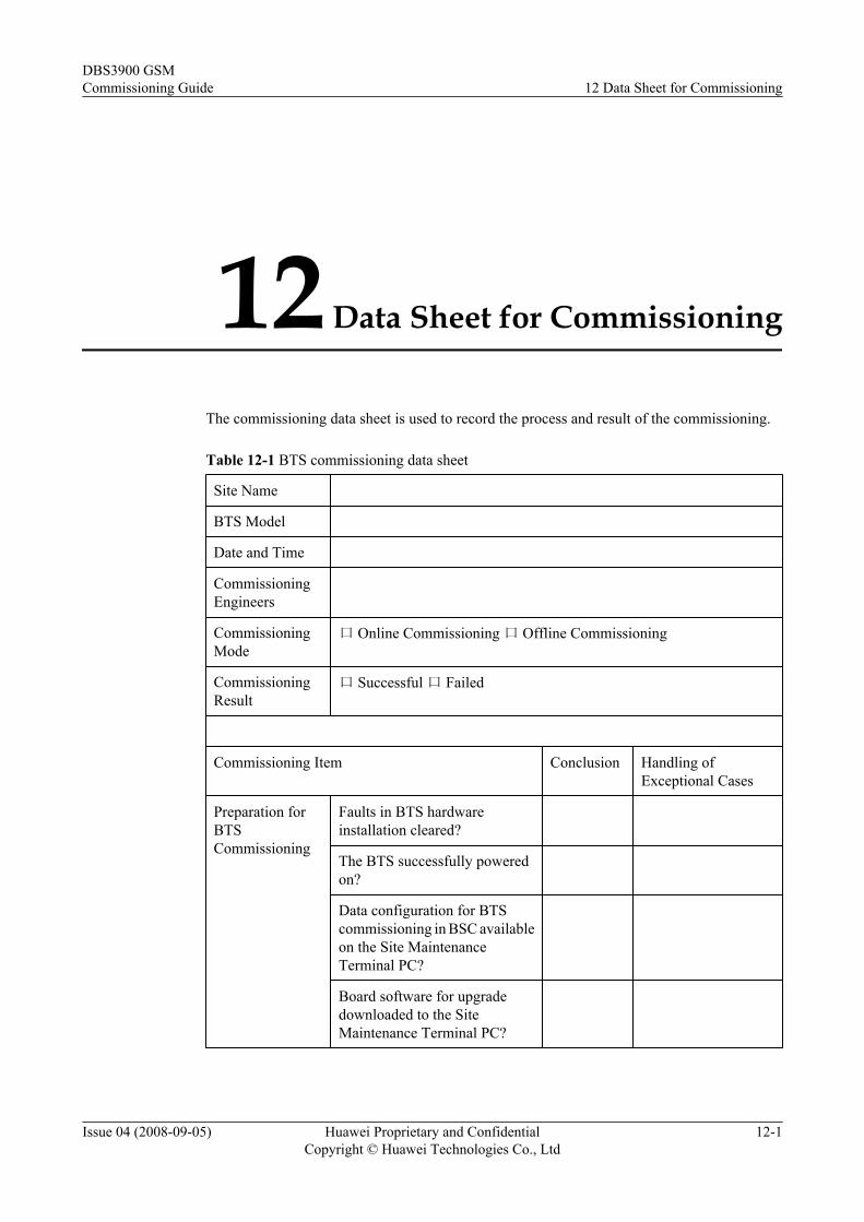
12 Data Sheet for Commissioning
The commissioning data sheet is used to record the process and result of the commissioning.
Table 12-1 BTS commissioning data sheet
Site Name
BTS Model
Date and Time
CommissioningEngineers
CommissioningMode
口 Online Commissioning 口 Offline Commissioning
CommissioningResult
口 Successful 口 Failed
Commissioning Item Conclusion Handling ofExceptional Cases
Preparation forBTSCommissioning
Faults in BTS hardwareinstallation cleared?
The BTS successfully poweredon?
Data configuration for BTScommissioning in BSC availableon the Site MaintenanceTerminal PC?
Board software for upgradedownloaded to the SiteMaintenance Terminal PC?
DBS3900 GSMCommissioning Guide 12 Data Sheet for Commissioning
Issue 04 (2008-09-05) Huawei Proprietary and ConfidentialCopyright © Huawei Technologies Co., Ltd
12-1
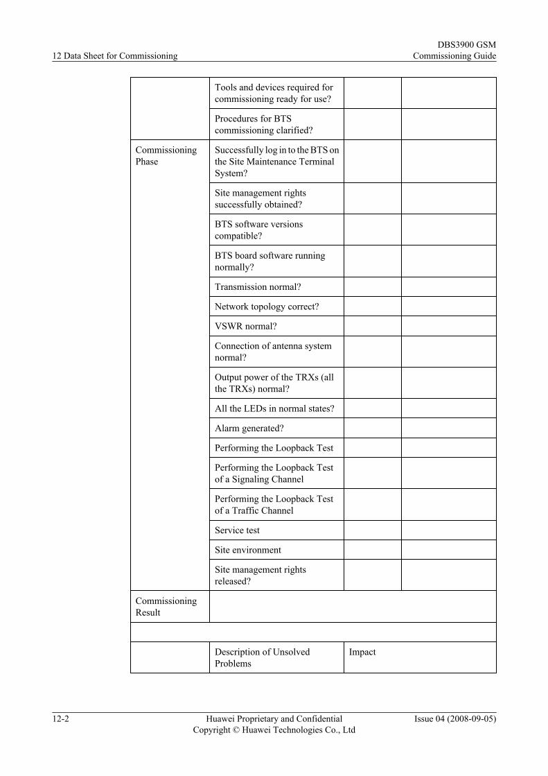
Tools and devices required forcommissioning ready for use?
Procedures for BTScommissioning clarified?
CommissioningPhase
Successfully log in to the BTS onthe Site Maintenance TerminalSystem?
Site management rightssuccessfully obtained?
BTS software versionscompatible?
BTS board software runningnormally?
Transmission normal?
Network topology correct?
VSWR normal?
Connection of antenna systemnormal?
Output power of the TRXs (allthe TRXs) normal?
All the LEDs in normal states?
Alarm generated?
Performing the Loopback Test
Performing the Loopback Testof a Signaling Channel
Performing the Loopback Testof a Traffic Channel
Service test
Site environment
Site management rightsreleased?
CommissioningResult
Description of UnsolvedProblems
Impact
12 Data Sheet for CommissioningDBS3900 GSM
Commissioning Guide
12-2 Huawei Proprietary and ConfidentialCopyright © Huawei Technologies Co., Ltd
Issue 04 (2008-09-05)
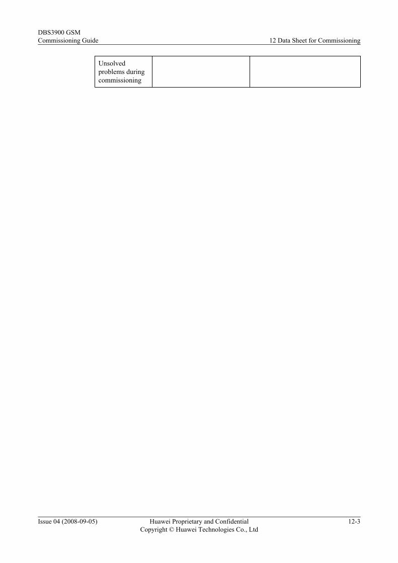
Unsolvedproblems duringcommissioning
DBS3900 GSMCommissioning Guide 12 Data Sheet for Commissioning
Issue 04 (2008-09-05) Huawei Proprietary and ConfidentialCopyright © Huawei Technologies Co., Ltd
12-3