Embed Size (px)
Citation preview

R a i l V e h i c l e S y s t e m s
NYR-332 Rev 17 7-23-2018 - en
Maintenance Specification DB10 Service Portions P/N I85200/001D, 775868 and 775868VR

Maintenance Specification DB10 Service Portions Doc.-No.: NYR-332 Revision: 17 7/23/18 - en
© 2018 New York Air Brake LLC - All rights reserved, including industrial property rights applications. New York Air Brake LLC retains any power of disposal, such as for copying and transferring.
Page 2 / 85
Contact Address
New York Air Brake
748 Starbuck Avenue
Watertown, NY 13601
USA
Phone: +1 315 786 5200
Fax: +1 315 786 5676
www.nyab.com
Revision History
Rev Date Name Para Description of change
01 12/13/1993 All Original Issue
02 1/15/1997 Revised to “E0” configuration changes
03 9/5/2000 Revised to include S-4015 information
04 1/16/2001 p. 26, sec.10.1 Removed color descr. from spring (25)
05 10/4/2005 Configuration updates (G0 and H0)
06 7/11/2006 Fig. 14, Item 3 P. 16, step 7 P. 30, step 2 tool drawings
Corrected orientation; Removed spring (25); Added yellow spring (25); Removed dimensions
07 9/29/06 Figure 14 Part 29A Config. changes Figure 7 Section 11.1.1 Section 11.1.3 Figures 9-11
Added part 29A; Included part 29A; Added “must be discarded”; Added reference; Added to lubrication note; Added torque value to Section 5; Added figures to document

Maintenance Specification DB10 Service Portions Doc.-No.: NYR-332 Revision: 17 7/23/18 - en
© 2018 New York Air Brake LLC - All rights reserved, including industrial property rights applications. New York Air Brake LLC retains any power of disposal, such as for copying and transferring.
Page 3 / 85
Rev Date Name Para Description of change
08 1/8/13 J. Shippee Section 6.4 Section 7.3 Section 8.3.2 Section 8.3.7 Section 7.2 Section 8.3.1 Section 11
Removed references to specific wrench; Added criteria; Removed references to specific wrench; Added specs for COT&S tag; Added K0 configuration upgrade; Removed Loctite statement; Updated illustrations; Reformatted document
09 12/16/13 J. Shippee Page 2 Table 1-1 Section 4 Section 5 Section 7.2 Section 8.1 Section 8.3.3 Section 8.3.4 Section 8.3.5 Section 8.3.6 Section 11
Added Confidentiality statement; Added PC-769140; removed M-914; Added gage P/Ns; Removed brake cylinder lubricant statement; reformatted section; Added illustration for Gauging steps; Added page #s to part references; Added gage references; Revised first Note; Revised first Note; removed ‘orange or white’ from steps 13 & 16; Removed two Notes; corrected item number in step 5; Updated Note (Loctite application); Removed Note (O-Rings/K-Rings); Updated Fig. 11-2; added Gage Dwgs.
10 4/28/14 J. Shippee Sec. 8.3.1 Updated guidelines on use of dissimilar metals during repair.
11 6/17/14 J. Shippee Table 7-1 Fig. 11-1, Ref. No. 19, (Red) was (Blue) and 5.3 turns was 5.5; corrected Figure Numbers and Reference Numbers.
12 3/13/15 J. Shippee Figure 7-3 Dimension 17.041 mm was 17.042 mm.
13 6/8/15 J. Shippee Sections 6.3.3 and 8.3.5
Sec. 7.2 (5b)
Sec. 7.3
Figure 11-2
Figure 11-4
All
Updated piston assembly / disassembly steps to include composite parts.
Removed ‘K0’ config. section.
Removed entire section (springs).
Provided separate illustrations for cast iron and aluminum versions.
Added CID Tag and Label.
Revised spring guidelines to 100% replacement.
14 6/27/16 J. Shippee Section 6.3.1
Section 8.3.6
Step 8 – Removed stem (22) from last sentence.
Step 4 – Removed ‘new’ from stem (22)

Maintenance Specification DB10 Service Portions Doc.-No.: NYR-332 Revision: 17 7/23/18 - en
© 2018 New York Air Brake LLC - All rights reserved, including industrial property rights applications. New York Air Brake LLC retains any power of disposal, such as for copying and transferring.
Page 4 / 85
Rev Date Name Para Description of change
Section 7
All
Added spring section (7.3)
Revised spring replacement guidelines to match parts catalog updates.
15 9/12/17 L. Vaughn 6.3.2
6.3.3
6.3.4
7.2
8.3.5
8.3.7
Added step to discard piston subassy.
Removed first half (incl. former ‘A’);
Added step to discard bushing.
Added step to discard piston.
Added step for installing Upgrade Kit;
Removed step for ‘B0’ config.
Removed former step 1A and Notice.
Updated Serial Prefix information.
16 11/21/17 J. Shippee Sec. 6, 7 & 8 Revised to add references to NYS-143 (Conversion for Vibration Upgrade).
17 7/23/18 J. Shippee All
Page 2
Pgs. 24,25,28
Added P/N 775868VR (w/Vib. Upgrade).
Removed Confidentiality Statement.
I85200/001D was I88500/001D (typo).
The original document was issued in English language.

Maintenance Specification DB10 Service Portions Doc.-No.: NYR-332 Revision: 17 7/23/18 - en
© 2018 New York Air Brake LLC - All rights reserved, including industrial property rights applications. New York Air Brake LLC retains any power of disposal, such as for copying and transferring.
Page 5 / 85
Table of Contents
1 GENERAL INFORMATION 9 1.1 Introduction 9 1.2 Technical Changes 9 1.3 Target Group for this Document 9 1.4 Referenced Documents 10 1.5 Danger, Warning, Caution, and Note (Notice) Messages 10
2 PRODUCT IDENTIFICATION 12 2.1 Serial Prefix Identification 12 2.2 Product Structure 16
3 SAFETY AWARENESS 17 3.1 General Safety Awareness 17
4 TOOLS REQUIRED 18 4.1 Standard Tools 18 4.2 Special Tools 18
5 ADHESIVES, LUBRICANTS, SEALANTS, AND SOLVENTS 19 5.1 Lubricants 19 5.2 Sealants 19
6 DISASSEMBLY 20 6.1 Cleaning 20 6.2 General Requirements 21 6.3 Disassembly of DB10 Service Portion 21 6.4 Disassembly of DB10 Release Valve 29
7 CLEANING, INSPECTING AND REPAIRING 35 7.1 Cleaning 35 7.2 Inspecting 35 7.3 Springs 41 7.4 Chokes 42 7.5 Rubber Parts 43 7.6 Filters and Accessory Parts 43

Maintenance Specification DB10 Service Portions Doc.-No.: NYR-332 Revision: 17 7/23/18 - en
© 2018 New York Air Brake LLC - All rights reserved, including industrial property rights applications. New York Air Brake LLC retains any power of disposal, such as for copying and transferring.
Page 6 / 85
8 LUBRICATING AND REASSEMBLY 44 8.1 Lubrication 44 8.2 Torque Requirements 44 8.3 Assembly of DB10 Service Portion 45
9 TESTING 60
10 MATERIAL HANDLING 60
11 SUPPORT INFORMATION 64 11.1 DB10 Service Portion Parts 64 11.2 Special Tools - Drawings 78 11.3 Abbreviations and Acronyms 85

Maintenance Specification DB10 Service Portions Doc.-No.: NYR-332 Revision: 17 7/23/18 - en
© 2018 New York Air Brake LLC - All rights reserved, including industrial property rights applications. New York Air Brake LLC retains any power of disposal, such as for copying and transferring.
Page 7 / 85
List of Figures
Figure 2-1 DB-60 Control Valve Operating Portions and Double-Sided Pipe Bracket ............................... 13
Figure 2-2 DB-60L Control Valve Operating Portions and Double-Sided Pipe Bracket ............................. 14
Figure 2-3 DB-60 Control Valve Operating Portions and Single-Sided Pipe Bracket ................................. 15
Figure 6-1 Removal and Installation Instructions for KNORR K-Rings (outer lip seal) ............................... 31
Figure 6-2 DB10 Service Portion Basic Valve (Assembly View) ................................................................. 32
Figure 6-3 DB10 Service Portion Basic Valve (Assembly View) ................................................................. 33
Figure 6-4 Release Valve (Assembly View) ................................................................................................ 34
Figure 7-1 Threaded Bushing (Item # 48 in Figure 11-2) .......................................................................... 39
Figure 7-2 Stem (Item # 13 in Figure 11-3) ................................................................................................ 40
Figure 7-3 Balancing Piston (Item # 41 in Figure 11-3) ............................................................................ 40
Figure 8-1 DB10 Service Portion Cover Subassembly ............................................................................... 50
Figure 8-2 Piston Assembly ........................................................................................................................ 55
Figure 8-3 Bushing with valve seat (Item 13) .............................................................................................. 56
Figure 8-4 Threaded Bushing (item 14) starting at S/N F0-XXXXX ............................................................ 57
Figure 10-1 Examples of Valve Portion Stenciling with Required Information ............................................ 61
Figure 10-2 DB10 Service Portion with Shipping Parts (Installed) .............................................................. 62
Figure 10-3 Shipping Parts .......................................................................................................................... 63
Figure 11-1 DB10 Service Portion (Exploded View) ................................................................................... 64
Figure 11-2a DB10 Housing Assembly – Aluminum (Exploded View) ........................................................ 67
Figure 11-2b DB10 Housing Assembly – Cast Iron (Exploded View)……………………………………….....68
Figure 11-3 DB10 Filler Piece Assembly (Exploded View) ......................................................................... 71
Figure 11-4 DB10 Release Valve (Exploded View) .................................................................................... 74
Figure 11-5 Quick Service Valve Removal Tool (P/N 772615) ................................................................... 78
Figure 11-6 Quick Service Inlet Valve Positioning Tool (P/N 772616) ........................................................ 78
Figure 11-7 Special Hand Drive Pin (P/N 772617) ..................................................................................... 79
Figure 11-8 Retaining Clamp (P/N 772618) ................................................................................................ 79
Figure 11-9 Guide Pin (P/N 772620) ........................................................................................................... 80
Figure 11-10 Spacer Ring Assembly Tool (P/N 773069) ............................................................................ 80
Figure 11-11 Protection Ring (P/N 772623) ................................................................................................ 81
Figure 11-12 Bushing Extractor (P/N 772624) ............................................................................................ 81
Figure 11-13 Retaining Ring Positioning Tool (P/N 772625) ...................................................................... 82
Figure 11-14 K-Ring Positioning Tool (P/N 772626) ................................................................................... 82
Figure 11-15 Thin Wall Type Mandrel (P/N 772628) .................................................................................. 83
Figure 11-16 12mm Bore Gage (P/N 790505)..........................................................................................83
Figure 11-17 17mm Bore Gage (P/N 790506)..........................................................................................84

Maintenance Specification DB10 Service Portions Doc.-No.: NYR-332 Revision: 17 7/23/18 - en
© 2018 New York Air Brake LLC - All rights reserved, including industrial property rights applications. New York Air Brake LLC retains any power of disposal, such as for copying and transferring.
Page 8 / 85
List of Tables
Table 1-1 Referenced Documents...............................................................................................................10
Table 7-1 Spring Identification.....................................................................................................................41
Table 7-2 Choke Identification.....................................................................................................................43
Table 8-1 Torque Requirements..................................................................................................................44
Table 11-1 Potential 100% Replacement Parts...........................................................................................77

Maintenance Specification DB10 Service Portions Doc.-No.: NYR-332 Revision: 17 7/23/18 - en
© 2018 New York Air Brake LLC - All rights reserved, including industrial property rights applications. New York Air Brake LLC retains any power of disposal, such as for copying and transferring.
Page 9 / 85
1 GENERAL INFORMATION
1.1 Introduction This description contains particulars specific to the DB10 Service Portions P/N I85200/001D, 775868 and 775868VR. This document defines the various procedures and information required to disassemble, clean, inspect, and re-assemble the Service Portions.
DANGER
PLEASE READ THIS DOCUMENT CAREFULLY FROM START TO FINISH ENSURING THE SAFETY OF OPERATION AND TO AVOID PERSONAL INJURIES AND DAMAGE TO EQUIPMENT.
1.2 Technical Changes NYAB reserves the right to change the equipment or this document at any time without giv-ing special notice.
1.3 Target Group for this Document
This document is intended for use by trained service technicians who:
have the skill, experience, safety awareness and professional ability
� to remove and install the equipment,
� to inspect, maintain and debug the equipment,
have read and understood this document from start to finish, and
are familiar with the safety codes and accident prevention regulations for these activi-ties.
NOTE
This document will be useful to other target groups as well, e.g. project engineers.
However, it does not claim to provide complete information for such target groups.

Maintenance Specification DB10 Service Portions Doc.-No.: NYR-332 Revision: 17 7/23/18 - en
© 2018 New York Air Brake LLC - All rights reserved, including industrial property rights applications. New York Air Brake LLC retains any power of disposal, such as for copying and transferring.
Page 10 / 85
1.4 Referenced Documents
Table 1-1 Referenced Documents
Doc. ID
Doc. No Title
1 PC-769140 Parts Catalog (Cast Iron)
2 PC-775868 Parts Catalog (Aluminum)
3 NYT-1199-C Test Code
4 IP-175 Repair Track Maintenance, DB-60 Type Freight Brake Equipment
5 NYS-143 DB10 and DB20/DB20L (Aluminum) Conversion to include Vibration Upgrade
1.5 Danger, Warning, Caution, and Note (Notice) Messages
The symbols indicate that important personal safety information follows. Carefully read and understand each safety related text message and apply the message to the operation and maintenance of the system as defined in the safety alert message. The following are definitions associated with the different safety alert message categories. The words DANGER, WARNING, and CAUTION are used to identify levels of hazard seriousness for the safety of the personnel and the equipment. The word DANGER is used to signify an immediate hazard and is used throughout this manual in the following manner:
DANGER
INDICATES AN IMMINENTLY HAZARDOUS SITUATION, WHICH IF NOT AVOIDED, WILL RESULT IN DEATH OR SERIOUS INJURY. THIS WORD IS TO BE LIMITED TO THE MOST EXTREME SITUA-TIONS.
The word WARNING is used to signify hazards or unsafe practices and is used throughout this manual in the following manner:
WARNING
FAILURE TO COMPLY WITH THESE INSTRUCTIONS MAY LEAD TO IRREVERSIBLE PHYSICAL INJURIES WHICH MAY HAVE FATAL CONSEQUENCES.

Maintenance Specification DB10 Service Portions Doc.-No.: NYR-332 Revision: 17 7/23/18 - en
© 2018 New York Air Brake LLC - All rights reserved, including industrial property rights applications. New York Air Brake LLC retains any power of disposal, such as for copying and transferring.
Page 11 / 85
The word CAUTION just like the word WARNING is used to signify hazards or unsafe practice in addition to equipment damage and is used throughout this manual in the following manner:
CAUTION
FAILURE TO COMPLY WITH THESE INSTRUCTIONS MAY LEAD TO PERSONAL INJURIES AND/OR TO DAMAGE TO THE UNIT OR THE ENVIRONMENT.
The NOTE (NOTICE) messages are used throughout this manual in the following manner:
NOTE
Notes do not contain any messages relevant to safety.
Notes contain useful hints and additional information used to highlight suggestions which will result in enhanced installation, reliability, or operation.
Safety messages/notes have a specific structure which is explained here for DANGER (This also applies to WARNINGS and CAUTIONS):
DANGER
SOURCE OF THE DANGER
CONSEQUENCES OF THE DANGER
REMEDIAL MEASURES
Notes do not contain any messages relevant to safety and are included only for the sake of com-pleteness.
NOTE
Notes contain useful hints and additional information about the unit.

Maintenance Specification DB10 Service Portions Doc.-No.: NYR-332 Revision: 17 7/23/18 - en
© 2018 New York Air Brake LLC - All rights reserved, including industrial property rights applications. New York Air Brake LLC retains any power of disposal, such as for copying and transferring.
Page 12 / 85
2 PRODUCT IDENTIFICATION
2.1 Serial Prefix Identification 1. The DB10 service portion has a nameplate that contains a serial number made up of Alpha and Nu-
meric characters.
The prefix characters of the serial number are an alpha/numeric combination located before the numeric characters. They identify the original manufacture revision level (example: first revision level starts with “A0”, second revision level is “B0”, etc.).
The numeric characters identify the valve production number (this number runs consecu-tively starting with 00001).
The suffix characters (if present), are an alpha/numeric combination and are located after the numeric characters. They identify the revision level of modifications, performed after ori-ginal manufacture (example: B0-00789-F0). This suffix is added by the facility that performs the modifications.
2. The nameplate on the DB10 Service Portion also contains a part number made up of numeric characters.
I85200/001D was made as either all cast iron or cast iron with aluminum covers before S/N G0-XXXXX. Starting with S/N G0-XXXXX it was made as all cast iron including the covers. During overhaul of cast iron valves, it is recommended that only cast iron covers be used on cast iron bodies and that aluminum covers only be used on aluminum bodies.
775868 and 775868VR are made as all aluminum including the covers.
Figure 1 Shows a ‘Front’ and ‘Rear’ view of a DB-60 control valve with a conven-tional style pipe bracket. It consists of a DB10 (Service Portion), DB20 (Emergen-cy Portion), and a DB-30 pipe bracket. The rear view shows the port connections for the car piping.
Figure 2 Shows a ‘Front’ and ‘Rear’ view of a DB-60L control valve with a conven-tional style pipe bracket. It consists of a DB10 (Service Portion), DB20L (Emer-gency Portion), and a DB30L pipe bracket. The rear view shows the port connec-tions for the car piping.
Figure 3 Shows a ‘Front’ and ‘Rear’ view of a DB-60 control valve with a single sided pipe bracket. It consists of a DB10 (Service Portion), DB20 (Emergency Portion), and a Single Sided DB30S pipe bracket. The rear view shows the port connections for the car piping. The DB-60SL version would contain a DB20L emergency portion in place of the DB20, and a DB30SL single sided pipe bracket in place of the DB30S single sided pipe bracket.

Maintenance Specification DB10 Service Portions Doc.-No.: NYR-332 Revision: 17 7/23/18 - en
© 2018 New York Air Brake LLC - All rights reserved, including industrial property rights applications. New York Air Brake LLC retains any power of disposal, such as for copying and transferring.
Page 13 / 85
Figure 2-1 DB-60 Control Valve Operating Portions and Double-Sided Pipe Bracket

Maintenance Specification DB10 Service Portions Doc.-No.: NYR-332 Revision: 17 7/23/18 - en
© 2018 New York Air Brake LLC - All rights reserved, including industrial property rights applications. New York Air Brake LLC retains any power of disposal, such as for copying and transferring.
Page 14 / 85
Figure 2-2 DB-60L Control Valve Operating Portions and Double-Sided Pipe Bracket

Maintenance Specification DB10 Service Portions Doc.-No.: NYR-332 Revision: 17 7/23/18 - en
© 2018 New York Air Brake LLC - All rights reserved, including industrial property rights applications. New York Air Brake LLC retains any power of disposal, such as for copying and transferring.
Page 15 / 85
Figure 2-3 DB-60 Control Valve Operating Portions and Single-Sided Pipe Bracket

Maintenance Specification DB10 Service Portions Doc.-No.: NYR-332 Revision: 17 7/23/18 - en
© 2018 New York Air Brake LLC - All rights reserved, including industrial property rights applications. New York Air Brake LLC retains any power of disposal, such as for copying and transferring.
Page 16 / 85
2.2 Product Structure
1. The service portion consists of the basic valve [housing (Fig. 6-2) and three covers (Fig. 6-3) with their interior parts], and the release valve [housing and two covers (Fig. 6-4) with their inte-rior parts].
2. The basic valve housing contains the following sub-components; main piston system, service
accelerated release valve, quick service limiting valve, emergency release AR-reduction valve and retaining check valve (see Fig. 6-2 and Fig. 6-3).
3. The subassembly cover contains the following sub-components; balancing piston (which is also
part of the main piston system), balancing valve, quick service valve, ER-charging check valve and charging valves for the auxiliary and emergency reservoirs (see Fig. 6-2 and Fig. 6-3).
4. The release valve housing contains the BC-release valve that contains a piston subassembly
and the AR and ER exhaust valves. (Refer to Fig. 6-4).

Maintenance Specification DB10 Service Portions Doc.-No.: NYR-332 Revision: 17 7/23/18 - en
© 2018 New York Air Brake LLC - All rights reserved, including industrial property rights applications. New York Air Brake LLC retains any power of disposal, such as for copying and transferring.
Page 17 / 85
3 SAFETY AWARENESS
3.1 General Safety Awareness
1. Observe all rules and regulations where the equipment is being used. Whenever there is a conflict between the instructions in this manual and the instructions of the user, the rules and regulations of the user will govern.
2. De-pressurize air system before loosening connections or components. Before removing any component from its mountings, the train must be safely parked. To prevent personal injury, all main reservoir, brake supply reservoir, and brake cylinder air pressure on the affected vehicle must be vented.
3. "Bottled" up air under pressure (even though air supply is cut off) may cause gaskets and/or particles of dirt to become airborne and sound levels to increase when any component part is removed from the equipment arrangement. Personal eye and ear protection must be worn and care taken to avoid possible injury when performing any work on these component parts.
4. The use of an air jet, which must be less than 30 PSI, to blow parts clean or to blow them dry after being cleaned with a solvent will cause particles of dirt and/or droplets of the cleaning sol-vent to be airborne. These particles and droplets may cause skin and /or eye irritation. Per-sonal eye protection must be worn to protect the eyes from possible injury. When using an air jet, do not direct it toward another person.
5. If degreasing fluids are used for cleaning purposes, the current local safety regulations plus the safety precautionary statements of the manufacturer of the cleaning agent must be adhered to. Otherwise, physical harm could result from the inhalation of toxic fumes. Make sure the area is well ventilated when working with materials that produce harmful fumes.
6. Personal eye protection must be worn when doing any work to protect eyes from possible inju-ry.
7. Where fasteners removed from the equipment are not satisfactory for reuse, care must be tak-en to select replacements that match the originals. Mismatched or incorrect fasteners can re-sult in equipment damage or malfunction, or possible personal injury.
8. To ensure the correct functioning of each component, use only the manufacturers genuine spare parts as replacements.
9. Follow all DANGERS, WARNINGS, CAUTIONS, and NOTES found throughout this specifica-tion. If you must use a work procedure or tool which is not recommended, you must first satisfy yourself that neither your safety, nor your fellow workers safety, nor that of the equipment will be jeopardized by the method selected.
10. Any person performing maintenance and/or operational tasks with the brake system and sys-tem components is required to have the appropriate job skill level, as governed by the user.
Maintenance Specification DB10 Service Portions Doc.-No.: NYR-332 Revision: 17 7/23/18 - en
© 2018 New York Air Brake LLC - All rights reserved, including industrial property rights applications. New York Air Brake LLC retains any power of disposal, such as for copying and transferring.
Page 18 / 85
4 TOOLS REQUIRED
Overhaul of the DB10 Service Portion will be accomplished in a more efficient and safe manner through the use of the following standard and special tools.
4.1 Standard Tools
1. Box end wrenches or square drive socket wrenches for hex cap screws with wrench openings of 9/16", 17/32", 3/4", 31/32", 1-5/8" and 1-13/16".
2. Allen wrenches with 3/16" and 15/64" width across flats.
3. A flat blade screwdriver for slotted head screws with screwdriver point dimensions of 3/64" x
11/32".
4. Offset snap ring pliers for internal retaining rings with 70°, 1/16" tip.
5. Offset pointed tweezers (7°) with overall length of approximately 5".
6. A pin punch with 0.1" diameter maximum pin dimension.
7. A metal marking scriber with a straight and a hooked end.
4.2 Special Tools A flat blade screwdriver for slotted head screws with a modified screwdriver point.
Use a standard flat blade screwdriver with screwdriver point dimensions of 3/64" x 11/32" and reduce the width of the blade from 11/32" to 10/32" maximum by grinding.
The following special tools are required. Drawings are shown in Section 11.
Quick Service Valve Removal Tool ................... Fig. 11-5..................P/N 772615
Quick Service Inlet Valve Positioning Tool ....... Fig. 11-6..................P/N 772616
Special Hand Drive Pin ..................................... Fig. 11-7..................P/N 772617
Retaining Clamp ................................................ Fig. 11-8..................P/N 772618
Guide Pin (3 required) ....................................... Fig. 11-9..................P/N 772620
Spacer Ring Assembly Tool .............................. Fig. 11-10................P/N 773069
Protection Ring .................................................. Fig. 11-11................P/N 772623
Bushing Extractor .............................................. Fig. 11-12................P/N 772624
Retaining Ring Positioning Tool ........................ Fig. 11-13.................P/N 772625

Maintenance Specification DB10 Service Portions Doc.-No.: NYR-332 Revision: 17 7/23/18 - en
© 2018 New York Air Brake LLC - All rights reserved, including industrial property rights applications. New York Air Brake LLC retains any power of disposal, such as for copying and transferring.
Page 19 / 85
K-Ring Positioning Tool ..................................... Fig. 11-14.................P/N 772626
Thin Wall Type Mandrel .................................... Fig. 11-15.................P/N 772628
12mm Bore Gage.............................................Fig. 11-16..................P/N 790505
17mm Bore Gage.............................................Fig. 11-17..................P/N 790506
Special tools may be either fabricated by the user or purchased through the OEM.
5 ADHESIVES, LUBRICANTS, SEALANTS, AND SOLVENTS
The followings lubricants and sealants / liquid fastening aids are used when assembling the DB10 Service Portion. Adhesives and solvents are not identified with in this document.
5.1 Lubricants Dow Corning 55 Silicone Grease
5.2 Sealants Loctite 242 Thread Sealant (Retaining Compound Type 2)
Alodine (brush-on)
Black Oxide Primer
Maintenance Specification DB10 Service Portions Doc.-No.: NYR-332 Revision: 17 7/23/18 - en
© 2018 New York Air Brake LLC - All rights reserved, including industrial property rights applications. New York Air Brake LLC retains any power of disposal, such as for copying and transferring.
Page 20 / 85
6 DISASSEMBLY
6.1 Cleaning 1. All maintenance work starts with the initial external cleaning of the control valve portion with
the shipping covers still in place (Refer to Fig. 10-2).
WARNING
DANGER OF PERSONAL INJURY EXISTS. WHEN USING SOLVENTS, BE SURE TO: WEAR EYE, SKIN, AND RESPIRATORY PROTECTION. WORK IN A WELL VENTILATED AREA. AVOID REPEATED OR PROLONGED CONTACT. KEEP SOLVENT CONTAINER CLOSED. KEEP SOLVENT AWAY FROM SPARKS, FLAMES, AND
HEAT. FAILURE TO OBSERVE THESE SAFETY PRECAUTIONS CAN LEAD TO INJURY OR INTOXICATION.
WARNING
DANGER OF PERSONAL INJURY EXISTS. WHEN USING COMPRESSED AIR, BE SURE TO: WEAR EYE PROTECTION. DO NOT EXCEED 30 PSI.
CAUTION
VALVE BODIES SHOULD NOT BE SUBMERGED IN A SOLUTION.
2. Once the valve body has been cleaned by an approved method, the shipping covers can be removed and disassembly may begin.
3. The DB10 Service Portion must be completely disassembled and all parts inspected, cleaned and lubricated at a suitable bench in a clean, well-lighted location in an A.A.R. ap-proved air brake shop.

Maintenance Specification DB10 Service Portions Doc.-No.: NYR-332 Revision: 17 7/23/18 - en
© 2018 New York Air Brake LLC - All rights reserved, including industrial property rights applications. New York Air Brake LLC retains any power of disposal, such as for copying and transferring.
Page 21 / 85
6.2 General Requirements 1. Use the tools specified in Section 4.0.
2. It is recommended that suitable devices be made to hold the valve bodies in place during the dis-assembly/assembly process. In addition, it would be helpful if the valve body could be rotated horizontally by 360 degrees on this device with locking features every 90 degrees.
3. Remove and install KNORR K-Rings only in accordance with the instructions given in Fig. 6-1.
4. If necessary, use the K-Ring Positioning Tool (Figure 11-14) and / or tweezers only, to re-move and install springs, valve plates, K-Rings or O-Rings.
5. Prevent damage or abrasion to all parts of the valve, particularly machined surfaces during di-sassembly, cleaning and assembly.
6. The covers are used not only as sealing surfaces, but also to support various component parts.
When removing/attaching covers and/or sub-components, exercise care to prevent the loss of
springs, chokes, valve seats or rubber parts.
7. Some covers are recessed at the flange face. These covers cannot be knocked off laterally. If they do not loosen automatically after cap screw removal, they can be pried out by inserting a
suitable flat blade screwdriver in the opposing, built-in recess.
8. The non-recessed covers should come off automatically by spring force once the cap screws
have been removed. If not, they can be tapped off laterally using a soft-faced mallet.
NOTE
For proper location of main piston system, valves, and chokes, refer to Figures 6-2, 6-3, and 6-4.
For proper location of all parts identified by reference number, refer to Section 11.
6.3 Disassembly of DB10 Service Portion
WARNING
COMPRESSED FORCES MAY INADVERTENTLY EXPEL PARTS. WEAR EYE PROTECTION AND EXERCISE CARE DURING DISASSEMBLY. FAILURE TO OBSERVE THESE SAFETY PRECAUTIONS CAN LEAD TO INJURY.

Maintenance Specification DB10 Service Portions Doc.-No.: NYR-332 Revision: 17 7/23/18 - en
© 2018 New York Air Brake LLC - All rights reserved, including industrial property rights applications. New York Air Brake LLC retains any power of disposal, such as for copying and transferring.
Page 22 / 85
NOTE
These instructions are to be performed after the DB10 Service Portion is removed from the DB30 Pipe Bracket and applies to DB10 Service Portions that are at any configuration level.
Distortion of bolts, nuts, etc. must be avoided by using tools espe-cially adapted for this work (Refer to Section 4).
Care must be taken to ensure that pistons, springs, chokes, rubber parts, etc. are protected from damage.
6.3.1 DISASSEMBLY OF DB10 SERVICE PORTION
(Refer to Figure 11-1)
NOTE
To hold the valve from moving during disassembly, it may be bene-ficial to attach the valve to a suitable holding fixture.
1. Remove cap screws (2 and 3) which secure the release valve housing (1) to the basic valve housing (6).
NOTE
Separate release valve housing (1) carefully to prevent the loss of valve parts.
2. Remove seven O-Rings (5) with K-Ring Positioning Tool (Fig. 11-14) before removing choke (4) (C 6.1) from release valve housing (1) flange face. Discard O-Rings (5).
3. Rotate the valve housing (6) so side cover (28) is face up.
CAUTION
EXERCISE CARE TO PREVENT DAMAGE TO THE MACHINED SEALING SURFACE ON THE OPPOSITE SIDE OF THE HOUS-ING WHEN ROTATING THE VALVE HOUSING.
CAUTION
REMOVE COVER (28) CAREFULLY TO PREVENT DAMAGE TO THE SEALING SURFACES.

Maintenance Specification DB10 Service Portions Doc.-No.: NYR-332 Revision: 17 7/23/18 - en
© 2018 New York Air Brake LLC - All rights reserved, including industrial property rights applications. New York Air Brake LLC retains any power of disposal, such as for copying and transferring.
Page 23 / 85
CAUTION
EXERCISE CARE TO PREVENT THE LOSS OF VALVE PARTS WHEN REMOVING COVER.
4. Remove cap screws (2) and lift off cover (28) carefully.
5. Use K-Ring Positioning Tool (Fig. 11-14) to extract O-Rings (5, 29, 37 and 38). Dis-card O-Rings (5, 29, 37 and 38).
6. Remove spring (33), spring guide (20), diaphragm (21), spring guide (10), spring (34)
and check valve (12). Discard check valve (12) and diaphragm (21).
7. Remove spring (30), check valve (31), retaining ring (31A) if present and filter (32). Discard check valve (31), filter (32) and retaining ring (31A) if present.
8. Remove spring (19), spring guide (20), diaphragm (21) and stem (22). Unscrew
threaded bushing (23) with a 3/4" socket wrench then remove check valves (24), spring (26), O-Ring (25), and bushing (27). Discard two check valves (24), O-Ring (25), spring (19) and diaphragm (21).
NOTE
If ring (9) is present and made of steel, protect the radius of threaded bushing (12) by using protection ring (Fig. 11-11) before removing steel ring (9) with a suitable screwdriver.
9. Remove spring (7), diaphragm (8), spacer ring (9) if present, spring guide (10) and check valve (12). Unscrew threaded bushing (13 or 14) with a 1-5/8" socket wrench. Remove spring guide (16), spring (17) and check valve (18) with tweezers. Discard check valves (12 & 18), spring (7) and diaphragm (8).
10. Remove and discard O-Ring (15) from threaded bushing (13 or 14).
11. Remove O-Ring (35) and choke (36) from housing (6). Discard O-Ring (35).
NOTE
If the valve is attached to a holding fixture, remove basic valve housing (6) for further disassembly.

Maintenance Specification DB10 Service Portions Doc.-No.: NYR-332 Revision: 17 7/23/18 - en
© 2018 New York Air Brake LLC - All rights reserved, including industrial property rights applications. New York Air Brake LLC retains any power of disposal, such as for copying and transferring.
Page 24 / 85
6.3.2 DISASSEMBLY OF DB10 HOUSING ASSEMBLY
(Refer to Figure 11-2)
NOTE
Remove filler piece assembly (68) slowly to prevent springs and spring-loaded parts from becoming airborne.
1. With filler piece assembly (68) facing up, remove cap screws (2). Lift off filler piece assembly (68). Remove and discard O-Ring (67) and then set filler piece assembly (68) to one side.
2. Remove piston subassembly (49-58) from housing (6).
For I85200/001D pre-N0 serial numbers and 775868 pre-N0 serial numbers excluding K0, dis-card piston subassembly (49-58). For 775868 pre-T0 serial numbers, refer to NYS-143 for Conversion to 775868VR.
WARNING
PARTS MAY BE INADVERTENTLY EXPELLED BY FORCE OF SPRING. WEAR EYE PROTECTION AND EXERCISE CARE DURING DISASSEMBLY. FAILURE TO OBSERVE THESE SAFETY PRECAUTIONS CAN LEAD TO INJURY.
6.3.3 DISASSEMBLY OF PISTON SUBASSEMBLY (49-58)
For Aluminum Service Portions P/N 775868 with S/N K0-XXXXX and starting with S/N N0-XXXXX:
Remove nut (52) and key (58) from piston plate (51).
1. Remove piston plate (51), stem (57) and diaphragm (50) from piston assembly (49). Discard diaphragm (50) and spring (53).
2. Remove and discard one O-Ring (61) and four O-Rings (37) from housing (6).
Maintenance Specification DB10 Service Portions Doc.-No.: NYR-332 Revision: 17 7/23/18 - en
© 2018 New York Air Brake LLC - All rights reserved, including industrial property rights applications. New York Air Brake LLC retains any power of disposal, such as for copying and transferring.
Page 25 / 85
WARNING
PARTS MAY BE INADVERTENTLY EXPELLED BY FORCE OF SPRING. WEAR EYE PROTECTION AND EXERCISE CARE DURING DISASSEMBLY. FAILURE TO OBSERVE THESE SAFETY PRECAUTIONS CAN LEAD TO INJURY.
3. Loosen threaded bushing (48) by using a 1-13/16" socket wrench.
4. Unscrew threaded bushing (48) carefully by hand, so the force of spring (45) is fully re-lieved before all parts of the main piston system are removed.
For I85200/001D pre-N0 serial numbers and 775868 pre-T0 serial numbers excluding K0, discard threaded bushing (48). For 775868 pre-T0 serial numbers, refer to NYS-143 for Conversion to 775868VR.
NOTE
If spring guide (46) is still in its locked position and spring (45) and piston stem (47) remain in housing (6), use Quick Service Inlet Valve Positioning Tool (Fig. 11-6) to release this locked position by pressing and carefully rotating spring guide (46) 90º counter-clockwise.
5. Remove check valve (11), stem (47), spring guide (46), and spring (45) from housing (6). Discard check valve (11).
6. Remove O-ring (40) from threaded bushing (48) and O-ring (38) from stem (47). Dis-
card O-rings (38 and 40). Refer to Section 7.2 for gauging and inspection guidelines for threaded bushing (48).
CAUTION
EXERCISE CARE TO PREVENT DAMAGE TO THE VALVE SEAT RADIUS OF STEM (47).
7. Visually inspect stem (47) per guidelines in Section 7.2. Unscrew and discard choke assembly (64 or 62) with a suitable Allen wrench or screwdriver.
8. Unscrew choke (65) with a suitable Allen wrench or screwdriver. Inspect choke (65)
per guidelines in Section 7.4.
9. Rotate basic valve housing (6) so that threaded bushing (39) is face up.
10. Loosen threaded bushing (39) by using a 1-13/16" socket wrench.

Maintenance Specification DB10 Service Portions Doc.-No.: NYR-332 Revision: 17 7/23/18 - en
© 2018 New York Air Brake LLC - All rights reserved, including industrial property rights applications. New York Air Brake LLC retains any power of disposal, such as for copying and transferring.
Page 26 / 85
WARNING
PARTS MAY BE INADVERTENTLY EXPELLED BY FORCE OF SPRING. WEAR EYE PROTECTION AND EXERCISE CARE DURING DISASSEMBLY. FAILURE TO OBSERVE THESE SAFETY PRECAUTIONS CAN LEAD TO INJURY.
11. Unscrew bushing (39) carefully by hand, so the force of spring (41) is fully relieved be-fore spring (41) and bushing (43) are removed.
12. Remove spring (41) and check valve (11) from housing (6). Discard check valve (11).
13. Remove and discard O-Ring (40) from threaded bushing (38). Inspect threaded bush-
ing (38) per general guidelines in Section 7.2.
14. Use K-Ring Positioning Tool (Fig. 11-14) to remove O-Ring (42) before removing valve seat bushing (43) with Bushing Extractor (Fig. 24). Discard O-Ring (42).
CAUTION
EXERCISE CARE TO PREVENT DAMAGE TO THE VALVE SEAT RADIUS OF VALVE SEAT BUSHING (43).
15. Remove and discard K-Ring (44) from bushing (43).
16. Use a suitable Allen wrench or screwdriver to unscrew choke (66) from the pipe bracket flange face of the basic valve housing (6). Visually inspect any straight-through bushing bores in housing (6) per guidelines in Section 7.2. Inspect choke (66) per guidelines in Section 7.4.
6.3.4 DISASSEMBLY OF DB10 FILLER PIECE ASSEMBLY
(Refer to Figure 11-3)
For Cast Iron Service Portions P/N I85200/001D with S/N A0-XXXXX thru S/N D0-XXXXX:
1. With cover (43) facing down, remove retaining ring (20) with suitable pliers. Remove
stem (17). Discard retaining ring (20).
2. Remove retaining ring (20) and stem (18) from cover (1). Use K-ring Positioning Tool (Fig. 11-14) to remove sealing ring (19) from the AR-charging valve chamber in housing (1). Discard sealing ring (19) and retaining ring (20).

Maintenance Specification DB10 Service Portions Doc.-No.: NYR-332 Revision: 17 7/23/18 - en
© 2018 New York Air Brake LLC - All rights reserved, including industrial property rights applications. New York Air Brake LLC retains any power of disposal, such as for copying and transferring.
Page 27 / 85
3. Discard stem (18).
4. Remove retaining ring (20) and balancing valve stem (13). Discard retaining ring (20).
CAUTION
EXERCISE CARE TO PREVENT DAMAGE TO THE VALVE SEAT RADIUS OF STEM (13).
5. Use K-Ring Positioning Tool (Fig. 11-14) to remove K-Ring (16), washer (15) and spring (14) from the balancing valve stem (13). Discard K-Ring (16). Visually inspect seat of stem (13) per general guidelines in Section 7.2. Refer to gauging guidelines in Section 7.2 for gauging length of stem (13).
6. Proceed to the next step for the remainder of disassembly.
For Cast Iron Service Portions P/N I85200/001D starting with S/N E0-XXXXX and Alumi-num Service Portions P/N 775868 starting with AO-XXXXX:
1. With cover (43) facing up, remove cap screws (44), with a 9/16" wrench. Lift off cover
(43).
NOTE
Remove cover (43) slowly to prevent springs and spring loaded parts from becoming airborne.
2. Remove pop rivet (47), by drilling the head of the rivet with a 3/16" drill (Ø 5 mm max.). Remove and discard rivet body (47), spacer ring (46) and vent flap (45) from cover (43).
CAUTION
EXERCISE CARE TO PREVENT CHIPS FROM REMAINING IN COVER (43).
NOTE
Use K-Ring Positioning Tool (Fig. 11-14) and/or tweezers whenev-er necessary.
3. Remove O-ring (2), spring (29), spring seat (24A) if present, check valve (23), bushing
(27) with attached O-rings (22), [sealing ring (19), and stem (18) starting at S/N E0-XXXXX for P/N I85200/001D and starting at S/N A0-XXXXX for P/N 775868], from cover (1). Discard check valve (23), O-rings (2 & 22) and sealing ring (19).

Maintenance Specification DB10 Service Portions Doc.-No.: NYR-332 Revision: 17 7/23/18 - en
© 2018 New York Air Brake LLC - All rights reserved, including industrial property rights applications. New York Air Brake LLC retains any power of disposal, such as for copying and transferring.
Page 28 / 85
4. Remove O-ring (33), bushing (32), check valve (31), and spring (30) from cover (1).
Discard O-ring (33) and check valve (31).
5. Remove O-ring (2), spring (28), check valve (23), bushing (27) with O-rings (22), [and stem (17) starting at S/N E0-XXXXX for P/N I85200/001D and starting at S/N A0-XXXXX for P/N 775868], from cover (1). Discard check valve (23) and O-Rings (2 & 22).
NOTE
Use Quick Service Valve Removal Tool (Fig. 11-5) to push out piston (5) and bushings (3 & 9).
6. Remove O-Ring (10), spring (12), check valve (11), bushing (9) with O-Rings (8), pis-
ton (5) with K-Rings (4 & 6) and O-Ring (7), and bushing (3) with O-Ring (2) from cov-er (1). Discard O-Rings (2, 7, 8 & 10), K-Rings (4 & 6) and check valve (11).
NOTE
For P/N I85200/001D, on units prior to S/N D0-XXXXX, remove O-Ring (2A) and discard. Do not replace.
7. Remove O-Ring (2), filter (26), spring (25 or 29A), (if present) spring seat (24), check valve (23), bushing (21) with two attached O-Rings (22), [stem (13) with attached spring (14), washer (15), and K-Ring (16) starting at S/N E0-XXXXX for P/N I85200/001D and starting at S/N A0-XXXXX for P/N 775868], from cover (1). Discard O-Rings (2 & 22), K-Ring (16), spring seat (24), check valve (23) and filter (26). In-spect bushing (21) per general guidelines in Section 7.2.
NOTE
Use Quick Service Valve Removal Tool (Fig. 11-5) to push out piston (41).
For I85200/001D pre-N0 serial numbers and 775868 pre-N0 serial numbers excluding K0, dis-card piston (41). For 775868 pre-T0 serial numbers, refer to NYS-143 for Conversion to 775868VR.
8. Remove O-ring (39), piston (41) with K-Rings (40 & 42), and bushing (38) with O-Rings (36 & 37) from cover (1). Discard O-Rings (36, 37 and 39) and K-Rings (40 & 42). Inspect bore of piston (41) per gauging guidelines in Section 7.2.
9. Remove and discard O-Rings (34 & 35) from cover (1).

Maintenance Specification DB10 Service Portions Doc.-No.: NYR-332 Revision: 17 7/23/18 - en
© 2018 New York Air Brake LLC - All rights reserved, including industrial property rights applications. New York Air Brake LLC retains any power of disposal, such as for copying and transferring.
Page 29 / 85
6.4 Disassembly of DB10 Release Valve
(Refer to Figure 11-4) 1. Rotate release valve portion so the release valve lower cover (30) is face up. Remove cap
screws (1). Lift off cover (30).
2. Remove sleeve (29), release valve handle (28), lifter (27), spring (26), stem (25), spring guide (23) and spring (22) from release valve housing assembly (7).
3. Remove and discard O-Ring (24) from stem (25). Inspect stem (25) per general guidelines in
Section 7.2.
CAUTION
EXERCISE CARE TO PREVENT CHIPS FROM REMAINING IN COVER (30).
4. Remove and discard pop rivet (33) by drilling the head of the rivet with 3/16" drill (Ø 5 mm max.).
5. Remove and discard spacer ring (32) and vent flap (31) from cover (30).
6. Remove and discard O-Ring (3) from housing (7) (use K-Ring Positioning Tool (Fig. 11-14) and / or tweezers).
7. Rotate service portion so the release valve upper cover (2) is face up. Remove cap screws
(1). Lift off cover (2).
CAUTION
EXERCISE CARE TO PREVENT DAMAGE TO THE VALVE SEAT RADIUS OF BUSHING (19).
NOTE
Use K-Ring Positioning Tool (Fig. 11-14) and/or tweezers whenev-er necessary.
8. Remove bushing (19), spring (20) and check valve (21) from housing assembly (7). Discard
check valve (21). Visually inspect seat and choke in bushing (19) per general guidelines in Section 7.2.
9. Remove and discard three O-Rings (3), O-Ring (8) and two O-Rings (18) from housing (7).
Maintenance Specification DB10 Service Portions Doc.-No.: NYR-332 Revision: 17 7/23/18 - en
© 2018 New York Air Brake LLC - All rights reserved, including industrial property rights applications. New York Air Brake LLC retains any power of disposal, such as for copying and transferring.
Page 30 / 85
10. Remove two springs (4), two check valves (5) and two stems (6) from housing (7). Discard check valves (5).
CAUTION
EXERCISE CARE TO PREVENT DAMAGE TO SEALING SURFACES.
11. Rotate release valve portion so the release valve lower cover (30) mounting surface is face up.
12. Unscrew self-locking hex nut (17) while holding piston (9) in place with a properly fitted screw-driver. Discard self-locking hex nut (17).
13. Remove bushing (16), check valve (14) and spring (13) from end of piston (9). Discard check
valve (14).
14. Remove and discard O-ring (15) from bushing (16).
15. Remove piston (9) from housing (7). Visually inspect both piston (9) and release valve bore and internal choke in housing (7) per general guidelines in Section 7.2.
16. Remove and discard two O-Rings (11 & 12) and K-Ring (10) from piston (9).

Maintenance Specification DB10 Service Portions Doc.-No.: NYR-332 Revision: 17 7/23/18 - en
© 2018 New York Air Brake LLC - All rights reserved, including industrial property rights applications. New York Air Brake LLC retains any power of disposal, such as for copying and transferring.
Page 31 / 85
Figure 6-1 Removal and Installation Instructions for KNORR K-Rings (outer lip seal)

Maintenance Specification DB10 Service Portions Doc.-No.: NYR-332 Revision: 17 7/23/18 - en
© 2018 New York Air Brake LLC - All rights reserved, including industrial property rights applications. New York Air Brake LLC retains any power of disposal, such as for copying and transferring.
Page 32 / 85
Figure 6-2 DB10 Service Portion Basic Valve (Assembly View)

Maintenance Specification DB10 Service Portions Doc.-No.: NYR-332 Revision: 17 7/23/18 - en
© 2018 New York Air Brake LLC - All rights reserved, including industrial property rights applications. New York Air Brake LLC retains any power of disposal, such as for copying and transferring.
Page 33 / 85
Figure 6-3 DB10 Service Portion Basic Valve (Assembly View)

Maintenance Specification DB10 Service Portions Doc.-No.: NYR-332 Revision: 17 7/23/18 - en
© 2018 New York Air Brake LLC - All rights reserved, including industrial property rights applications. New York Air Brake LLC retains any power of disposal, such as for copying and transferring.
Page 34 / 85
Figure 6-4 Release Valve (Assembly View)

Maintenance Specification DB10 Service Portions Doc.-No.: NYR-332 Revision: 17 7/23/18 - en
© 2018 New York Air Brake LLC - All rights reserved, including industrial property rights applications. New York Air Brake LLC retains any power of disposal, such as for copying and transferring.
Page 35 / 85
7 CLEANING, INSPECTING AND REPAIRING
7.1 Cleaning
WARNING
DANGER OF PERSONAL INJURY EXISTS. WHEN USING SOLVENTS, BE SURE TO: WEAR EYE, SKIN, AND RESPIRATORY PROTECTION. WORK IN A WELL VENTILATED AREA. AVOID REPEATED OR PROLONGED CONTACT. KEEP SOLVENT CONTAINER CLOSED. KEEP SOLVENT AWAY FROM SPARKS, FLAMES, AND
HEAT. FAILURE TO OBSERVE THESE SAFETY PRECAUTIONS CAN LEAD TO INJURY OR INTOXICATION.
CAUTION
VALVE BODIES SHOULD NOT BE SUBMERGED IN A SOLUTION.
1. After complete disassembly, all parts, including the interior of the body, must be thoroughly cleaned by an approved method that will dissolve oil and grease without damage or abrasion to the parts.
WARNING
DANGER OF PERSONAL INJURY EXISTS. WHEN USING COMPRESSED AIR, BE SURE TO: WEAR EYE PROTECTION. DO NOT EXCEED 30 PSI.
2. All parts, including the body, must be blown dry after cleaning.
3. Light surface corrosion on cast iron or aluminum parts must be removed by carefully cleaning with crocus cloth or emery paper. Corrosion protection that was removed and exposes bare metal must be re-applied to the affected area. For aluminum parts, apply a brush-on Alodine solution. For cast iron parts, apply a black oxide primer. Applications must be applied accord-ing to the manufacturer’s specifications listed on the container.
7.2 Inspecting 1. Carefully inspect cleaned parts. If damaged (cracked, deformed or signs of rust or thread
damage), replace component.

Maintenance Specification DB10 Service Portions Doc.-No.: NYR-332 Revision: 17 7/23/18 - en
© 2018 New York Air Brake LLC - All rights reserved, including industrial property rights applications. New York Air Brake LLC retains any power of disposal, such as for copying and transferring.
Page 36 / 85
2. Visually inspect sealing, sliding and guide surfaces for scoring, scratches and excessive wear. Also examine valve seats for scoring, scratches and indentations.
3. Replace parts if scoring or scratches deeper than 0.2 mm are detected on sealing, sliding or guide surfaces, or if smaller defects cannot be fully removed during reconditioning.
4. Replace all parts that are cracked, broken, worn, damaged, or in such a condition as would result in unsatisfactory operation.
5. MANDATORY COMPONENT MODIFICATIONS:
“Mandatory Component Modifications” MUST be made to all DB-10 Service Portions that are still equipped with parts/part combinations listed in this section. If necessary, order new parts/part combinations per the parts catalog. All of the following modifications MUST be done to the Service Portions. After completing these modifications, the nameplate must be stamped with the appropriate suffix after or be-low the existing serial number per the instructions in section 8.3.7.
NOTE
For I85200/001D pre-N0 configurations the following must be discarded and replaced with components in Vibration Up-grade Kit 793751:
Balancing Valve Piston (Figure 11-3, Item 41) Quick Service Inlet Valve Bushing (Figure 11-2a, Item 48) Service Piston Subassembly (Figure 11-2a, Items 49-58)
NOTE
For 775868 pre-T0 configurations excluding K0, refer to NYS-143 for Conversion to 775868VR, including Vibration Upgrade.
a. For Part Number I85200/001D:
A0 - Configuration
If Present: Spring (Plain) (7), must be discarded. (See Figure 11-1)
Replace with: Spring (Green) (7). (Used on Service portions starting with S/N A0-XXXXX).
D0 – Configuration
If Present: Combination of Bushing (Brass) (26) with filter element, spring (29A), and O-
Ring (2A) must be discarded. (See Figure 11-3)

Maintenance Specification DB10 Service Portions Doc.-No.: NYR-332 Revision: 17 7/23/18 - en
© 2018 New York Air Brake LLC - All rights reserved, including industrial property rights applications. New York Air Brake LLC retains any power of disposal, such as for copying and transferring.
Page 37 / 85
Replace with: Filter (non-metallic) with stainless steel strainer (26), spring (25) and spring seat (24). (Used on Service portions starting with S/N D0-XXXXX). O-Ring (2A) has been deleted.
H0 – Configuration
If Present: Stability Choke Assembly with flat center face (59, 60, 61, 62 & 63), must be
discarded. (See Figure 11-2)
Replace with: Stability Choke Assembly (64) with raised center face. (Used on Service portions starting with S/N H0-XXXXX).
Non Configuration Change Modifications
If Present: Bushing (Aluminum) (39), must be discarded. (See Figure 11-2)
Replace with: Bushing (Brass) (39)
b. For Part Number 775868:
G0 – Configuration
If Present: Stability Choke Assembly with flat center face (59, 60, 61, 62 & 63), must be
discarded. (See Figure 11-2)
Replace with: Stability Choke Assembly (64) with raised center face. (Used on Service portions starting with S/N G0-XXXXX).
6. NON-MANDATORY COMPONENT MODIFICATIONS
If damage or excessive wear is present on the part/parts listed in the “If Damaged” category, perform the component modification(s) in the “Replace with” category.
a. For Part Number I85200/001D
C0 - Configuration
If damaged: Filter (sintered brass) (32), and star washer (31). (Parts deleted starting
with S/N C0-XXXXX). (See Figure 11-1)
Replace with: Filter (non-metallic) (32). (Used on Service portions starting with S/N C0-XXXXX).
If damaged: Spacer Ring (9) (metallic). (See Figure 11-1)
Replace both parts with: Spacer Ring (9) (non-metallic).

Maintenance Specification DB10 Service Portions Doc.-No.: NYR-332 Revision: 17 7/23/18 - en
© 2018 New York Air Brake LLC - All rights reserved, including industrial property rights applications. New York Air Brake LLC retains any power of disposal, such as for copying and transferring.
Page 38 / 85
E0 - Configuration
If Old Style filler Piece sub-assembly (68) (housing with press-fit bushings) is dam-aged: Part deleted starting with S/N E0-XXXXX. (See Figure 11-2)
Replace with: New style filler piece assembly (68). (Used on Service portions
starting with S/N E0-XXXXX).
F0 – Configuration
If damaged: Bushing (12) and Spacer Ring (9). (See Figure 11-1)
Replace with: Bushing (13). (Used on service portions starting with S/N F0-XXXXX).
G0 – Configuration
Identifies the all cast iron portion (body and covers). K0 – Configuration If damaged: Spring Guide (11) (Used on service portions before S/N K0-XXXXX). (See
Figure 11-1) Replace with: Spring Guide (10) (Used on service portions starting with K0-XXXXX).
b. For Part Number 775868:
B0, C0, D0 and E0 – Configuration
No component modifications, factory information only.
F0 – Configuration
If damaged: Bushing (12) and Spacer Ring (9). (See Figure 11-1)
Replace with: Bushing (13). (Used on service portions starting with S/N F0-XXXXX).
J0 – Configuration If damaged: Spring Guide (11) (Used on service portions before S/N J0-XXXXX). (See
Figure 11-1) Replace with: Spring Guide (10) (Used on service portions starting with J0-
XXXXX).

Maintenance Specification DB10 Service Portions Doc.-No.: NYR-332 Revision: 17 7/23/18 - en
© 2018 New York Air Brake LLC - All rights reserved, including industrial property rights applications. New York Air Brake LLC retains any power of disposal, such as for copying and transferring.
Page 39 / 85
K0 – Configuration Composite parts used on service portions with S/N K0-XXXXX do not need to be re-placed. They are now used on service portions starting with S/N N0-XXXXX.
NOTE
Once “Mandatory” or “Non-Mandatory” component modifications are performed, refer to Section 8.3.7 “Nameplate Identification” for proper labeling.
7. GAUGING:
Threaded Bushing (48) (Fig. 11-2) (page 67)
Maximum allowable diameter of large bore is 12.027 mm (see Figure 7-1). If greater than 12.027 mm, then the component must be replaced. Use 12mm Bore Gage (Figure 11-16) to measure diameter.
Figure 7-1 Threaded Bushing (Item # 48 in Figure 11-2)
Stem (13) (Fig. 11-3) (page 71) – Visually inspect seat of stem per general guidelines in Sec-tion 7.2. Minimum allowable length of component is 34.350 mm. If less than 34.350 mm, then the component must be replaced.

Maintenance Specification DB10 Service Portions Doc.-No.: NYR-332 Revision: 17 7/23/18 - en
© 2018 New York Air Brake LLC - All rights reserved, including industrial property rights applications. New York Air Brake LLC retains any power of disposal, such as for copying and transferring.
Page 40 / 85
Figure 7-2 Stem (Item # 13 in Figure 11-3)
Balancing Piston (41) (Fig. 11-3) (page 71) – maximum allowable inside entry diameter is 17.041 mm (see Figure 7-3). If greater than 17.041 mm, then the component must be re-placed. Use 17mm Bore Gage (Figure 11-17) to measure diameter.
Figure 7-3 Balancing Piston (Item # 41 in Figure 11-3)

Maintenance Specification DB10 Service Portions Doc.-No.: NYR-332 Revision: 17 7/23/18 - en
© 2018 New York Air Brake LLC - All rights reserved, including industrial property rights applications. New York Air Brake LLC retains any power of disposal, such as for copying and transferring.
Page 41 / 85
7.3 Springs 1. If not discarded and replaced, all springs must be inspected after cleaning.
2. Springs that show distortion, corrosive pitting, cracks, or have permanent set, must be re-jected and replaced by springs known to be correct.
3. For proper spring identification, refer to Table 7-1.
4. There are 21 springs used throughout the service portion.
5. Spring (4), (Fig. 11-4) is required twice; all others once.
6. Table 7-1 is intended for identification only and should not be used for any other purpose. It does not represent specifications for these springs. Actual springs may vary due to small differences in dimensions.
Table 7-1 Spring Identification
Fig. No.
Ref. No.
Designation Approx.
Outside Dia. mm (inch)
Approx. Wire Dia. mm
(inch)
Approx.
Free Height mm (inch)
Approx. No.
of Turns
11-1 7 Service Accelerated Release
Valve Spring (Green) 19.3 (0.763) 1.5 (0.055) 26 (1.090) 5.5
11-1 17 Back Flow Check Valve
Spring 16 (0.630) 0.8 (0.031) 22.1 (0.870) 10.5
11-1 19 QS Limiting Valve Spring
(Red) 19.3 (0.760) 1.5 (0.059) 29.3 (1.153) 5.3
11-1 26 QS Limiting Check Valve
Spring 10.3 (0.406) 0.8 (0.031) 14.6 (0.575) 8.5
11-1 30 Retaining Check Valve Spring 11.5 (0.453) 0.5 (0.020) 31.2 (1.228) 5.5
11-1 33 Emergency Release AR Re-
duction Valve Spring 17.8 (0.700) 1.8 (0.071) 28.3 (1.115) 5.0
11-1 34 Emergency Release AR Re-duction Check Valve Spring
8.8 (0.347) 0.8 (0.031) 25 (0.990) 14.5
11-2 41 AR/BC Inlet Valve Spring 16.6 (0.654) 1.6 (0.063) 45.2 (1.780) 8.5
11-2 45 QS Inlet Valve Spring 28.25 (1.112) 2.25 (0.089) 80.85 (3.183) 8.5
11-2 53 Balancing Piston Spring 47.2 (1.858) 3.2 (0.126) 87 (3.425) 6.5
11-3 12 QS Valve Spring 11.8 (0.464) 0.8 (0.031) 15.9 (0.625) 6.5
11-3 14 Balancing Valve Spring 10.8 (0.425) 0.8 (0.031) 21.1 (0.831) 6.5
11-3 25 Balancing Check Valve Spring 10.5 (0.413) 1.0 (0.039) 22.3 (0.878) 8.0
11-3 28 ER Charging Valve Spring
(Blue) 10.4 (0.409) 0.9 (0.036) 22.3 (0.877) 6.5
Maintenance Specification DB10 Service Portions Doc.-No.: NYR-332 Revision: 17 7/23/18 - en
© 2018 New York Air Brake LLC - All rights reserved, including industrial property rights applications. New York Air Brake LLC retains any power of disposal, such as for copying and transferring.
Page 42 / 85
Fig. No.
Ref. No.
Designation Approx.
Outside Dia. mm (inch)
Approx. Wire Dia. mm
(inch)
Approx.
Free Height mm (inch)
Approx. No.
of Turns
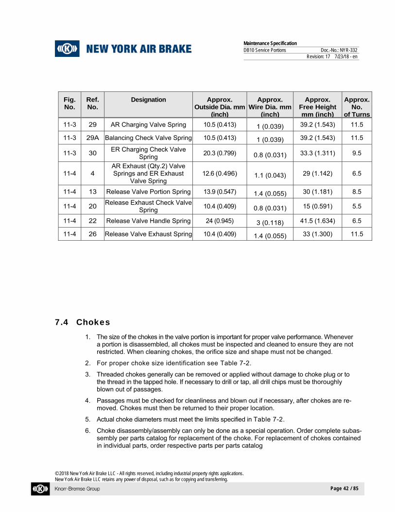
11-3 29 AR Charging Valve Spring 10.5 (0.413) 1 (0.039) 39.2 (1.543) 11.5
11-3 29A Balancing Check Valve Spring 10.5 (0.413) 1 (0.039) 39.2 (1.543) 11.5
11-3 30 ER Charging Check Valve
Spring 20.3 (0.799) 0.8 (0.031) 33.3 (1.311) 9.5
11-4 4 AR Exhaust (Qty.2) Valve Springs and ER Exhaust
Valve Spring 12.6 (0.496) 1.1 (0.043) 29 (1.142) 6.5
11-4 13 Release Valve Portion Spring 13.9 (0.547) 1.4 (0.055) 30 (1.181) 8.5
11-4 20 Release Exhaust Check Valve
Spring 10.4 (0.409) 0.8 (0.031) 15 (0.591) 5.5
11-4 22 Release Valve Handle Spring 24 (0.945) 3 (0.118) 41.5 (1.634) 6.5
11-4 26 Release Valve Exhaust Spring 10.4 (0.409) 1.4 (0.055) 33 (1.300) 11.5
7.4 Chokes 1. The size of the chokes in the valve portion is important for proper valve performance. Whenever
a portion is disassembled, all chokes must be inspected and cleaned to ensure they are not restricted. When cleaning chokes, the orifice size and shape must not be changed.
2. For proper choke size identification see Table 7-2.
3. Threaded chokes generally can be removed or applied without damage to choke plug or to the thread in the tapped hole. If necessary to drill or tap, all drill chips must be thoroughly blown out of passages.
4. Passages must be checked for cleanliness and blown out if necessary, after chokes are re-moved. Chokes must then be returned to their proper location.
5. Actual choke diameters must meet the limits specified in Table 7-2.
6. Choke disassembly/assembly can only be done as a special operation. Order complete subas-sembly per parts catalog for replacement of the choke. For replacement of chokes contained in individual parts, order respective parts per parts catalog

Maintenance Specification DB10 Service Portions Doc.-No.: NYR-332 Revision: 17 7/23/18 - en
© 2018 New York Air Brake LLC - All rights reserved, including industrial property rights applications. New York Air Brake LLC retains any power of disposal, such as for copying and transferring.
Page 43 / 85
Table 7-2 Choke Identification
Fig. No.
Choke No.
Ref. No.
Designation
Dia. min. / max. mm (inch)
15 C 3.1 26 QS Limiting Valve Charging Choke 0.900/0.960 (0.0354/0.0378)
15 C 4.1 36 Retaining Check Valve Choke 0.700/0.760 (0.0276/0.0299)
15 C 6.1 4 Release Valve Exhaust Control Choke 0.700/0.760 (0.0276/0.0299)
16 C 1.3 60 Stability Choke 0.200/0.225 (0.0079/0.0089)
16 C 1.6 65 Sensitivity Choke 1.300/1.360 (0.0512/0.0535)
16 C 1.8 66 BC Release Choke 2.420/2.460 (0.0945/0.0969)
17 C 1.4 18 Retarded Recharge Choke 1.400/1.460 (0.0551/0.0575)
17 C 1.5 32 ER Charging Check Valve Choke 0.700/0.760 (0.0276/0.0299)
17 C 1.7 26 Balancing Pressure Exhaust Choke 0.400/0.480 (0.0157/0.0189)
17 C 5.1 9 QS Pressure Exhaust Choke 1.000/1.060 (0.0394/0.0417)
18 C 6.2 18 Release Valve Charging Control Choke 0.500/0.530 (0.0197/0.0209)
18 C 6.3 * Release Valve Reset Control Choke 0.600/0.630 (0.0236/0.0248)
* NOTE
This choke is part of a release valve subassembly. It is located either adjacent to the bushing, or it is integrated into the bushing that release valve piston rod (9) fits into. (See Figure 6-4)
7.5 Rubber Parts 1. All rubber parts must be replaced with new parts when reassembling the valve. All items
can be identified for ordering purposes per the parts catalog.
2. New rubber parts that have been in storage for more than five years must not be used.
3. The storage area for rubber parts must be cool, dark, and free from dampness and mildew. Since most rubber goods are affected by ozone, they must not be stored near electrical equipment that may generate ozone.
7.6 Filters and Accessory Parts
All filters and accessory parts have to be replaced by new parts when reassembling the valves. All items are part of a separate Repair Kit, which has to be ordered per the parts catalog.

Maintenance Specification DB10 Service Portions Doc.-No.: NYR-332 Revision: 17 7/23/18 - en
© 2018 New York Air Brake LLC - All rights reserved, including industrial property rights applications. New York Air Brake LLC retains any power of disposal, such as for copying and transferring.
Page 44 / 85
8 LUBRICATING AND REASSEMBLY
8.1 Lubrication
1. All sliding surfaces and all parts with their respective grooves should be coated with a light film of Dow Corning 55 Silicone Grease. Remove excess grease by wiping.
NOTE
Coat O-Rings and K-Rings with only a light film of grease. Do not apply grease to check valves and diaphragms. Wipe face of new check valves to ensure a contaminant-free surface.
2. During re-assembly of valve portions, only use the Thin Wall Type Mandrel (Fig. 11-5) in order to prevent damage to specific O-Rings.
3. The supply of O-Rings kept on a mandrel must not exceed daily requirements to prevent perma-nent stretch. In addition, caution must be used to protect against contamination from dirt and for-eign matter damaging O-Rings and lubricant.
NOTE
To prevent restriction of small orifices, do not apply grease to the threads of the main piston assembly.
8.2 Torque Requirements When reassembling DB10 Service Portions, cap screws and nuts must be tightened sufficiently to prevent gasket leakage, and yet not so tight as to cause distortion of covers and gaskets. For cor-rect torque values for the Service Portion, refer to Table 8-1 below.
Recommended torque values for cap screws, nuts and threaded bushings are listed in the follo-wing tabulation:
Table 8-1 Torque Requirements
FIG. No. PART NAME & ITEM No. TORQUE LIMITS IN FOOT POUNDS (Nm)
11-1 Cover Cap Screw (2) & (3) 20 to 24 (28 to 32)
11-1 Threaded Bushing (12), (13), (22) 10 to 15 (14 to 20)
11-2 Cover Cap Screw (2) & (3) 20 to 24 (28 to 32)
Maintenance Specification DB10 Service Portions Doc.-No.: NYR-332 Revision: 17 7/23/18 - en
© 2018 New York Air Brake LLC - All rights reserved, including industrial property rights applications. New York Air Brake LLC retains any power of disposal, such as for copying and transferring.
Page 45 / 85
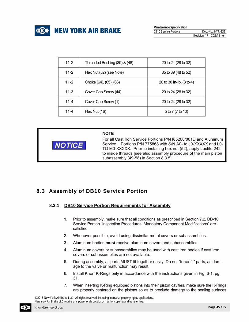
11-2 Threaded Bushing (39) & (48) 20 to 24 (28 to 32)
11-2 Hex Nut (52) (see Note) 35 to 39 (48 to 52)
11-2 Choke (64), (65), (66) 20 to 30 in-lb. (3 to 4)
11-3 Cover Cap Screw (44) 20 to 24 (28 to 32)
11-4 Cover Cap Screw (1) 20 to 24 (28 to 32)
11-4 Hex Nut (16) 5 to 7 (7 to 10)
NOTE
For all Cast Iron Service Portions P/N I85200/001D and Aluminum Service Portions P/N 775868 with S/N A0- to J0-XXXXX and L0- TO M0-XXXXX: Prior to installing hex nut (52), apply Loctite 242 to inside threads [see also assembly procedure of the main piston subassembly (49-58) in Section 8.3.5].
8.3 Assembly of DB10 Service Portion
8.3.1 DB10 Service Portion Requirements for Assembly
1. Prior to assembly, make sure that all conditions as prescribed in Section 7.2, DB-10 Service Portion “Inspection Procedures, Mandatory Component Modifications” are satisfied.
2. Whenever possible, avoid using dissimilar metal covers or subassemblies.
3. Aluminum bodies must receive aluminum covers and subassemblies.
4. Aluminum covers or subassemblies may be used with cast iron bodies if cast iron covers or subassemblies are not available.
5. During assembly, all parts MUST fit together easily. Do not "force-fit" parts, as dam-age to the valve or malfunction may result.
6. Install Knorr K-Rings only in accordance with the instructions given in Fig. 6-1, pg. 31.
7. When inserting K-Ring equipped pistons into their piston cavities, make sure the K-Rings are properly centered on the pistons so as to preclude damage to the sealing surfaces
Maintenance Specification DB10 Service Portions Doc.-No.: NYR-332 Revision: 17 7/23/18 - en
© 2018 New York Air Brake LLC - All rights reserved, including industrial property rights applications. New York Air Brake LLC retains any power of disposal, such as for copying and transferring.
Page 46 / 85
during installation.
8. When placing the covers on the housings of the DB-10 Service Portion, be sure all rubber diaphragms and O-Rings are seated properly in their respective grooves so they are not pinched or damaged when the covers are applied.
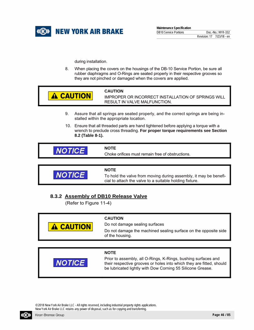
CAUTION
IMPROPER OR INCORRECT INSTALLATION OF SPRINGS WILL RESULT IN VALVE MALFUNCTION.
9. Assure that all springs are seated properly, and the correct springs are being in-stalled within the appropriate location.
10. Ensure that all threaded parts are hand tightened before applying a torque with a wrench to preclude cross threading. For proper torque requirements see Section 8.2 (Table 8-1).
NOTE
Choke orifices must remain free of obstructions.
NOTE
To hold the valve from moving during assembly, it may be benefi-cial to attach the valve to a suitable holding fixture.
8.3.2 Assembly of DB10 Release Valve (Refer to Figure 11-4)
CAUTION
Do not damage sealing surfaces
Do not damage the machined sealing surface on the opposite side of the housing.
NOTE
Prior to assembly, all O-Rings, K-Rings, bushing surfaces and their respective grooves or holes into which they are fitted, should be lubricated lightly with Dow Corning 55 Silicone Grease.

Maintenance Specification DB10 Service Portions Doc.-No.: NYR-332 Revision: 17 7/23/18 - en
© 2018 New York Air Brake LLC - All rights reserved, including industrial property rights applications. New York Air Brake LLC retains any power of disposal, such as for copying and transferring.
Page 47 / 85
NOTE
Metal to metal surfaces need to be coated with a light film of grease. Use K-Ring Positioning Tool (Fig. 11-14) and/or tweezers if nec-essary to assemble parts. Bottom cover (30) surface should be facing up. Before inserting all items, make sure the choke size (C6.3 in Fig-ure 6-4) located in the plugged bushing (16) under the release valve piston (9) is free of obstructions.
NOTE
Exercise care to prevent the loss of valve parts. Use the Thin Wall Type Mandrel (Fig. 11-15) to prevent damage to O-Rings (11 & 12) during assembly.
1. Install two new lightly greased O-Rings (11 & 12) and new lightly greased K-Ring (10)
onto piston (9).
2. Insert piston (9) into housing (7).
3. Install new lightly greased O-Ring (15) onto bushing (16).
4. Install spring (13), new check valve (14), bushing (16) and new nut (17) onto piston (9). Hold piston (9) in place and with a properly fitting screwdriver, then torque nut (17) to 5-7 ft lbs. (7-10 Nm).
5. Rotate release valve so cover (2) face is up.
CAUTION
Do not damage the valve seat radius of bushing (19).
6. Place new O-Rings (3), new O-Ring (18) and new O-Ring (8) onto top cover (2) face of housing (7).
7. Install new lightly greased O-Ring (18) onto bushing (19).
8. Insert new check valve (21), spring (20) and bushing (19) into housing (7).
9. Insert two stems (6), two new check valves (5) and two springs (4) into housing (7).

Maintenance Specification DB10 Service Portions Doc.-No.: NYR-332 Revision: 17 7/23/18 - en
© 2018 New York Air Brake LLC - All rights reserved, including industrial property rights applications. New York Air Brake LLC retains any power of disposal, such as for copying and transferring.
Page 48 / 85
10. Place cover (2) onto housing (7) and secure in place with cap screws (1). Torque screws (1) to 20-24 ft lbs. (28-32 Nm).
11. Rotate release valve so cover (30) face is up.
12. Install new lightly greased O-ring (3) onto housing (7).
13. Insert new vent flap (31) and new spacer ring (32) into cover (30).
14. Insert pop rivet (33) into spacer ring (32), vent flap (31) and cover (30) and secure in place.
15. Install new lightly greased O-ring (24) onto stem (25).
16. Install spring (22), spring guide (23), stem (25), spring (26) and lifter (27) into release valve housing (7).
17. Install while holding release valve handle (28) and sleeve (29) in place in cover (30).
18. Place cover (30) onto housing (7) and secure in place with cap screws (1). Torque cap screws (1) to 20-24 ft lbs. (28-32 Nm)
8.3.3 Assembly of DB10 Filler Piece
(Refer to Figure 11-3) (Includes parts seen in dotted box at top of drawing)
OLD FILLER PIECE INSTRUCTIONS for P/N I85200/001D Cast Iron Service Potions with S/N A0-XXXXX through S/N D0-XXXXX that are NOT having "E0" modification performed. (See sec-tion 10.1 and 10.2)
NOTE
Use K-Ring Positioning Tool (Fig. 11-14), tweezers and suitable pliers only. Refer to Fig. 8-1 for proper location of the auxiliary reservoir charging valve (18), the emergency reservoir charging valve (17) and the balancing valve (13).
1. Insert ER stem (17) and new retaining ring (20) into ER hole in cover assembly (1).

Maintenance Specification DB10 Service Portions Doc.-No.: NYR-332 Revision: 17 7/23/18 - en
© 2018 New York Air Brake LLC - All rights reserved, including industrial property rights applications. New York Air Brake LLC retains any power of disposal, such as for copying and transferring.
Page 49 / 85
2. Install new AR sealing ring (19) into cover assembly (1) and insert stem (18) and new retaining ring (20) into AR hole in cover assembly (1).
3. Insert spring (14), washer (15), and new lightly greased K-Ring (16) onto stem (13) then insert stem (13) and new retaining ring (20) into balancing valve hole in cover as-sembly (1).
4. Replace remaining parts by following “New Filler Piece Instructions”. Disregard steps that include stems (13, 17 and 18) w/associated parts and bushings (21 and 27) with O-Rings (2 and 22).
For P/N I85200/001D Cast Iron Service Potions with S/N A0-XXXXX through S/N C0-XXXXX: Spring (25) with yellow coloring and new filter (26) must be used in step 8.

Maintenance Specification DB10 Service Portions Doc.-No.: NYR-332 Revision: 17 7/23/18 - en
© 2018 New York Air Brake LLC - All rights reserved, including industrial property rights applications. New York Air Brake LLC retains any power of disposal, such as for copying and transferring.
Page 50 / 85
Figure 8-1 DB10 Service Portion Cover Subassembly

Maintenance Specification DB10 Service Portions Doc.-No.: NYR-332 Revision: 17 7/23/18 - en
© 2018 New York Air Brake LLC - All rights reserved, including industrial property rights applications. New York Air Brake LLC retains any power of disposal, such as for copying and transferring.
Page 51 / 85
NEW FILLER PIECE INSTRUCTIONS [for Aluminum Service Portions P/N 775868 and Cast Iron Service Portions P/N I85200/001D starting with S/N E0-XXXXX or that are having the "E0" modification performed]
(Refer to Figure 11-3)
1. Install new vent flap (45) and new spacer ring (46) onto cover assembly (43) using a new pop rivet (47).
2. Place cover assembly (43) side of cover (1) facing up.
3. Assemble new O-Rings (36 & 37) onto bushing (38). Insert bushing (38) into cover
(1).
NOTE
Piston (41) is part of Conversion covered in NYS-143 to include Vibration Upgrade.
4. Assemble new K-Rings (40 & 42) onto piston (41). Insert piston (41), into bushing (38).
NOTE
If necessary, use Quick Service Valve Removal Tool (Fig. 11-5) to install pistons.
5. Place new O-ring (39) onto cover (1).
6. Place spring (14) and washer (15) onto stem (13) and then secure in place with new K-Ring (16). Place stem assembly (13 thru 16) into cover (1).
7. Place two new O-Rings (22) onto bushing (21). Place bushing (21) into cover (1), and
place new check valve (23) into bushing (21).
NOTE
To aid in assembly, apply a dab of Dow Corning 55 Silicone Grease to radius end of spring seat (24), (this will help seat, spring, and filter stand upright).
8. Place new spring seat (24) into spring (25). Place new O-ring (2) on the spring side of
the new filter (26), then place filter (26) on other end of spring (25). Place parts (24 thru 26) into cover (1).
9. Assemble new O-Ring (2) onto bushing (3). Insert bushing (3) into cover (1).

Maintenance Specification DB10 Service Portions Doc.-No.: NYR-332 Revision: 17 7/23/18 - en
© 2018 New York Air Brake LLC - All rights reserved, including industrial property rights applications. New York Air Brake LLC retains any power of disposal, such as for copying and transferring.
Page 52 / 85
10. Assemble new K-Rings (4 & 6) and new O-Ring (7) onto piston (5). Insert piston (5)
into bushing (3).
11. Assemble new O-Rings (8) onto bushing (9). Insert bushing (9) and new O-Ring (10) into cover (1).
12. Place new check valve (11) on top of bushing (9) (flat side down). Place spring (12)
onto check valve (11).
13. Place white plastic stem (17) into cover (1). Assemble two new O-Rings (22) onto OD of bushing (27). Place bushing (27) into cover (1).
14. Place new check valve (23) and spring (28) into bushing (27). Place new O-Ring (2)
into cover (1).
15. Place spring (30), new check valve (31), and bushing (32) into cover (1). Place new O-Ring (33) into cover (1).
16. Place white plastic stem (18) into cover (1). Place new sealing ring (19) into ID of
bushing (27) and new O-Rings (22) onto OD of bushing (27). Place bushing (27) into cover (1).
17. Place new check valve (23), new spring seat (24) and spring (29) into bushing (27).
Place new O-Ring (2) into cover (1).
18. Assemble new O-Rings (34 & 35) into cover (1).
NOTE
It is very important to make sure that springs are not resting on rubber section of check valves (this will cause leakage) before installing cover assembly (43) to filler cover (1). It is also im-portant to ensure that all protruding bore assemblies in filler cover (1) are vertical and line up squarely with adjoining cavities in cover assembly (43). It is recommended that three (3) Guide Pins (Fig. 11-7) be used when installing cover assembly (43) to filler cover (1). Place cover (43) on filler cover (1) and secure with cap screws (44). Torque cap screws (44) to 20-24 ft-lbs (28-32 N-M).

Maintenance Specification DB10 Service Portions Doc.-No.: NYR-332 Revision: 17 7/23/18 - en
© 2018 New York Air Brake LLC - All rights reserved, including industrial property rights applications. New York Air Brake LLC retains any power of disposal, such as for copying and transferring.
Page 53 / 85
8.3.4 Assembly of DB10 Housing Assembly
(Refer to Figure 11-2)
1. Place filler piece assembly (68), mounting surface side of housing (6) facing down.
CAUTION
DO NOT DAMAGE THE VALVE SEAT RADIUS OF BUSHING (43).
2. Install new lightly greased K-Ring (44) into Body (6) and insert bushing (43) into housing (6).
3. Insert new O-Ring (42) onto housing (6) on top of valve seat bushing (43).
4. Install new O-Ring (40) onto brass style threaded bushing (39). (See section 7.2)
5. Insert new check valve (12) and spring (41) into housing (6).
WARNING
PARTS MAY BE INADVERTENTLY EXPELLED BY FORCE OF SPRING. WEAR EYE PROTEC-TION AND EXERCISE CARE DURING ASSEM-BLY. FAILURE TO OBSERVE THESE SAFETY PRECAUTIONS CAN LEAD TO INJURY.
6. Place threaded bushing (39) into housing (6). Use a 1-13/16" socket wrench and torque bushing (39) to 10-15 ft lbs. (14-20 Nm).
7. With filler piece assembly (68) (bottom face) side of housing (6) facing up and back face of body (6) facing forward, screw chokes (65 & 66) into housing (6). Torque chokes (65 & 66) to 20-30 in lbs. (3-4 Nm).
8. Install new stability choke assembly (64) into place with a suitable Allen wrench and
torque to 20-30 in-lbs (3-4 Nm).
CAUTION
DO NOT DAMAGE THE VALVE SEAT RADIUS OF VALVE STEM (47).

Maintenance Specification DB10 Service Portions Doc.-No.: NYR-332 Revision: 17 7/23/18 - en
© 2018 New York Air Brake LLC - All rights reserved, including industrial property rights applications. New York Air Brake LLC retains any power of disposal, such as for copying and transferring.
Page 54 / 85
9. Install new O-Ring (38) onto stem (47) and new O-Ring (40) onto threaded bushing
(48) using K-Ring Positioning Tool (Fig. 11-14).
WARNING
PARTS MAY BE INADVERTENTLY EXPELLED BY FORCE OF SPRING (45) IF SPRING GUIDE (46) IS NOT SECURELY LOCKED IN PLACE. SLOWLY REMOVE THE QUICK SERVICE INLET VALVE POSITIONING TOOL (FIG. 11-6) TO CHECK THAT SPRING GUIDE (46) IS SECURELY IN ITS LOCKED POSITION. FAILURE TO OB-SERVE THESE SAFETY PRECAUTIONS CAN LEAD TO INJURY.
10. Insert spring (45) and spring guide (46) into housing (6). Use Quick Service Inlet
Valve Positioning Tool (Fig. 11-6) to compress spring guide (46) and spring (45). Once compressed, lock spring guide (46) in place by rotating it ½ turn in either direc-tion.
11. Insert piston stem (47) and new check valve (11) (rubber side of check valve should
be visible after installation) into housing (6).
NOTE
Bushing (48) is part of Conversion covered in NYS-143 to include Vibration Upgrade.
12. Insert threaded bushing (48) into housing (6). Use a 1-13/16" socket wrench and
torque bushing (48) to 10-15 ft lbs. (14-20 Nm).
13. Insert new O-Ring (61) and four new O-Rings (37) into their proper grooves in housing (6).
8.3.5 Assembly of Piston Subassembly (49 thru 58)
NOTE
Piston Subassembly (49 thru 58) is part of Conversion covered in NYS-143 to include Vibration Upgrade.
NOTE
If any of the following parts need to be replaced, new parts must have the same part number as the original parts: piston (49), plate (51), nut (52), and spring (53).

Maintenance Specification DB10 Service Portions Doc.-No.: NYR-332 Revision: 17 7/23/18 - en
© 2018 New York Air Brake LLC - All rights reserved, including industrial property rights applications. New York Air Brake LLC retains any power of disposal, such as for copying and transferring.
Page 55 / 85
For Aluminum Service Portions P/N 775868 with S/N K0-XXXXX and starting with S/N N0-XXXXX:
Place new diaphragm (50) with bead facing up, plate (51), nut (52) and key (58) onto piston
(49).
WARNING
PARTS MAY BE INADVERTENTLY EXPELLED BY FORCE OF SPRING. WEAR EYE PROTEC-TION AND EXERCISE CARE DURING ASSEM-BLY. FAILURE TO OBSERVE THESE SAFETY PRECAUTIONS CAN LEAD TO INJURY.
1. Place new spring (53), guide (54), guide ring (55) and new retaining ring (56) onto pis-
ton assembly (49).
2. To insert new retaining ring (56), push down spring guide (54) against the force of spring (53) by aid of the Retaining Clamp (Fig. 11-8) and a press.
3. Use the Retaining Ring Positioning Tool (Fig. 11-13) to push the new retaining ring
(56) into its groove in the piston (49).
4. Ensure that the stem (57) of the piston (49) is still in place. See Figure 8-2.
Figure 8-2 Piston Assembly
5. Insert piston subassembly (49-58) into housing (6).
6. Install new O-Ring (67) onto filler piece assembly (68) and attach filler piece assembly (68) onto housing (6) using cap screws (2). Torque cap screws (2) to 20-24 ft lbs. (28-32 Nm).
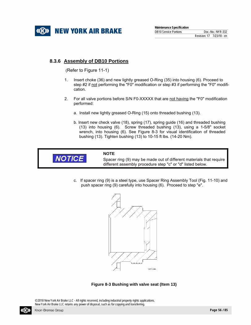
Maintenance Specification DB10 Service Portions Doc.-No.: NYR-332 Revision: 17 7/23/18 - en
© 2018 New York Air Brake LLC - All rights reserved, including industrial property rights applications. New York Air Brake LLC retains any power of disposal, such as for copying and transferring.
Page 56 / 85
8.3.6 Assembly of DB10 Portions
(Refer to Figure 11-1)
1. Insert choke (36) and new lightly greased O-Ring (35) into housing (6). Proceed to step #2 if not performing the "F0" modification or step #3 if performing the "F0" modifi-cation.
2. For all valve portions before S/N F0-XXXXX that are not having the "F0" modification
performed:
a. Install new lightly greased O-Ring (15) onto threaded bushing (13).
b. Insert new check valve (18), spring (17), spring guide (16) and threaded bushing (13) into housing (6). Screw threaded bushing (13), using a 1-5/8" socket wrench, into housing (6). See Figure 8-3 for visual identification of threaded bushing (13). Tighten bushing (13) to 10-15 ft lbs. (14-20 Nm).
NOTE
Spacer ring (9) may be made out of different materials that require different assembly procedure step "c" or "d" listed below.
c. If spacer ring (9) is a steel type, use Spacer Ring Assembly Tool (Fig. 11-10) and push spacer ring (9) carefully into housing (6). Proceed to step "e".
Figure 8-3 Bushing with valve seat (Item 13)

Maintenance Specification DB10 Service Portions Doc.-No.: NYR-332 Revision: 17 7/23/18 - en
© 2018 New York Air Brake LLC - All rights reserved, including industrial property rights applications. New York Air Brake LLC retains any power of disposal, such as for copying and transferring.
Page 57 / 85
d. If spacer ring (9) is a plastic type, it can be inserted without a tool. Proceed to step "e".
e. Install new check valve (12), spring guide (10), spacer ring (9), new diaphragm (8)
and new spring (7) into housing (6) on top of threaded bushing (13). Proceed to step # 4.
3. For all valve portions starting with S/N F0-XXXXX or that are having the"F0" modifica-
tion performed (See section 7.2):
a. Install new lightly greased O-ring (15) onto threaded bushing (14). See Figure 8-4.
Figure 8-4 Threaded Bushing (item 14) starting at S/N F0-XXXXX
b. Insert new check valve (18), spring (17), spring guide (16) and threaded bushing (14) into housing (6). Screw threaded bushing (14), using a 1-5/8" socket wrench, into housing (6). Tighten bushing (14) to 10-15 ft lbs. (14-20 Nm). Install new check valve (12), spring guide (10), new diaphragm (8) and new spring (7) into housing (6) on top of threaded bushing (14). Proceed to step # 4.
4. Insert bushing (27), new lightly greased O-Ring (25), two new check valves (24), spring
(26), and threaded bushing (23) into housing (6). With a 3/4" socket wrench, torque threaded bushing (23) to 10-15 ft lbs. (14-20 Nm). Install stem (22), new diaphragm (21), spring guide (20) and new spring (19) into housing (6) on top of threaded bushing (23).

Maintenance Specification DB10 Service Portions Doc.-No.: NYR-332 Revision: 17 7/23/18 - en
© 2018 New York Air Brake LLC - All rights reserved, including industrial property rights applications. New York Air Brake LLC retains any power of disposal, such as for copying and transferring.
Page 58 / 85
5. For Cast Iron valve portions, P/N I85200/001D, before S/N C0-XXXXX that are not having the "C0" modification performed:
Insert new filter (32), retaining ring (31A), new check valve (31) and spring (30) into
housing (6). Proceed to step # 7.
6. For Cast Iron valve portions, P/N I85200/001D, starting with S/N C0-XXXXX or that are having the "C0" modification performed:
Insert new filter (32), new check valve (31) and spring (30) into housing (6). Pro-
ceed to step # 7.
7. Insert new check valve (12), spring (34), spring guide (10), new diaphragm (21), spring guide (20) and spring (33) into housing (6).
8. Place new lightly greased O-Rings (29), (37), (38) and (5) into their respective grooves
on the cover (28) face of housing (6). It is recommended that two alignment pins are used during installation of cover (28).
9. Place cover (28) onto housing (6) and secure in place with cap screws (2). Torque cap
screws (2) to 20-24 ft lbs. (28-32 Nm).
10. Position valve body (6) so that release valve mounting is face-up.
11. Insert choke (4) and seven new lightly greased O-Rings (5) into release valve housing (1).
12. Place release valve (1) onto housing (6) and secure together with cap screws (2 and 3).
Tighten screws (2 & 3) to 20-24 ft lbs. (28-32 Nm).
8.3.7 Nameplate Identification for DB10
1. After performing all of the mandatory modifications listed in section 7.2 and assembly is completed, look on the nameplate of the DB-10 Service Portion. If the data stamped on it is illegible or the nameplate is damaged or missing, the nameplate must be replaced.
2. Replacement nameplates are available by contacting NYAB or a NYAB representa-
tive. Replacement nameplates will have an assigned serial number with the current mandatory modification as a suffix.
3. If the DB-10 Service Portion has been upgraded by performing any of the modifica-
tions from section 7.2, it must be stamped with the applicable suffix after, or below, the existing serial number to identify that the mandatory valve modifications have been performed.
Maintenance Specification DB10 Service Portions Doc.-No.: NYR-332 Revision: 17 7/23/18 - en
© 2018 New York Air Brake LLC - All rights reserved, including industrial property rights applications. New York Air Brake LLC retains any power of disposal, such as for copying and transferring.
Page 59 / 85
4. As an alternative method to steps 2 and 3 above, a COT&S tag may be attached to DB-10 in place of the nameplate:
Warranty information will consist of a bolt-on tag and adhesive label. Adhesive label shall include: repair location, part number, test date and warranty
expiration date. Serial prefix (engineering revision) shall be a two letter indicator stamped into the
bolt-on tag or a two letter indicator printed on the adhesive tag. No serialization is required
5. Since most repair facilities completely strip all internal components from the body and
they do not stay linked to the body that they came out of, the non-mandatory modifica-tions may or may not remain in a portion that was originally manufactured with them. By design, a portion is backward and forward compatible with respect to the non-mandatory modifications. Mandatory modifications are not backward compatible. It is necessary to know a portions status of mandatory modifications in order to ensure that the required repairs are correctly identified and performed. Therefore the repaired por-tion shall be stamped with the most current mandatory modification.
6. For P/N I85200/001D (769140):
Any mandatory modifications that occurred after the portion’s manufacture date must be performed on the repaired portion before it can have the configuration letter repre-senting the latest mandatory modification as its suffix on the nameplate. For example, an older manufactured portion after repair might be stamped ‘B0-XXXXX-M0’, indicat-ing that the original ‘B0’ configuration was upgraded to a mandatory ‘M0’ configuration. Always consult with NYAB for the current mandatory modifications.
7. For P/N 775868:
Serial Prefix A0-R0: Follow instructions in NYS-143 for Conversion including
Vibration Upgrade. Serial Prefix T0 and higher: Any mandatory modifications that occurred after the
portion’s manufacture date must be performed on the repaired portion before it can have the configuration let-ter representing the latest mandatory modification as its suffix on the nameplate. Always consult with NYAB for the current mandatory modifications.

Maintenance Specification DB10 Service Portions Doc.-No.: NYR-332 Revision: 17 7/23/18 - en
© 2018 New York Air Brake LLC - All rights reserved, including industrial property rights applications. New York Air Brake LLC retains any power of disposal, such as for copying and transferring.
Page 60 / 85
9 TESTING
1. After the completion of the above, the DB-10 Service Portion must be tested in accordance with the instructions given in Test Document NYT-1199-C.
2. Service Portions that have successfully passed testing must be identified and marked.
3. A suitable surface of the Service portion must be stenciled with letters at least ½” high in ac-cordance with Figure 10-1.
4. Cleaned and repaired Service Portions must pass prescribed tests on the A.A.R. standard test rack in accordance with Test Instructions NYT-1199-C.
5. After the DB-10 Service Portion has passed this Code of Tests and has been removed from the test rack, it must be stenciled and a shipping cover must be applied. The shipping cover must not be removed until the portion is ready to be installed on a car.
10 MATERIAL HANDLING
1. When the Service portion is not attached to the pipe bracket, a special shipping cover and gas-ket must be fitted to the valve portion for protection against dirt and damage (see Fig. 10-2 and 10-3).
2. These covers and guards must be applied to the Valve Portions as soon as they have passed the Code of Tests on the test rack and must not be removed until the cleaned valve portion is ready to be applied to the rail vehicle. Even then, special precautions must be taken to avoid damaging the parts or getting dirt into the operating portions when applying them.
3. The shipping cover, shown in Fig. 10-3, pg. 63, can be used for all currently A.A.R. approved Service portions.
4. The release valve stem guards, shown in Fig. 10-3, pg. 63, are provided to protect the internal
parts from damage.
5. These stem guards must be applied to the release valve stem and held in place by a 3/16" (Nominal Size ø 5 mm) cotter pin before transporting the valve portion.

Maintenance Specification DB10 Service Portions Doc.-No.: NYR-332 Revision: 17 7/23/18 - en
© 2018 New York Air Brake LLC - All rights reserved, including industrial property rights applications. New York Air Brake LLC retains any power of disposal, such as for copying and transferring.
Page 61 / 85
Figure 10-1 Examples of Valve Portion Stenciling with Required Information

Maintenance Specification DB10 Service Portions Doc.-No.: NYR-332 Revision: 17 7/23/18 - en
© 2018 New York Air Brake LLC - All rights reserved, including industrial property rights applications. New York Air Brake LLC retains any power of disposal, such as for copying and transferring.
Page 62 / 85
UPPORT INFORMATIO
Figure 10-2 DB10 Service Portion with Shipping Parts (Installed)

Maintenance Specification DB10 Service Portions Doc.-No.: NYR-332 Revision: 17 7/23/18 - en
© 2018 New York Air Brake LLC - All rights reserved, including industrial property rights applications. New York Air Brake LLC retains any power of disposal, such as for copying and transferring.
Page 63 / 85
N
SHIPPING COVER
RELEASE VALVE STEM GUARDS
Figure 10-3 Shipping Parts

Maintenance Specification DB10 Service Portions Doc.-No.: NYR-332 Revision: 17 7/23/18 - en
© 2018 New York Air Brake LLC - All rights reserved, including industrial property rights applications. New York Air Brake LLC retains any power of disposal, such as for copying and transferring.
Page 64 / 85
11 SUPPORT INFORMATION
11.1 DB10 Service Portion Parts
Figure 11-1 DB10 Service Portion (Exploded View)

Maintenance Specification DB10 Service Portions Doc.-No.: NYR-332 Revision: 17 7/23/18 - en
© 2018 New York Air Brake LLC - All rights reserved, including industrial property rights applications. New York Air Brake LLC retains any power of disposal, such as for copying and transferring.
Page 65 / 85
KEY for FIGURE 11-1
Item No. Description
1. DB10 Release Valve Portion
2. Hex Head Cap Screw
3. Hex Head Cap Screw
4. Release Valve Exhaust Control Choke
5. O-Ring
6. DB10B Housing Assembly
7. Service Accelerated Release Valve Spring
8. Service Accelerated Release Valve Diaphragm
9. Spacer Ring (Part deleted starting with S/N F0-XXXXX)
10. Spring Guide (Used on portions starting w/ S/N J0-XXXXX)
11. Spring Guide (Used on portions before S/N J0-XXXXX)
12. Check Valve
13. Threaded Bushing (Used on portions before S/N F0-XXXXX)
14. Threaded Bushing (Used on portions starting with S/N F0-XXXXX)
15. O-Ring
16. Service Accelerated Release Valve Spring Guide
17. Back Flow Check Valve Spring
18. Back Flow Check Valve
19. Quick Service Limiting Valve Spring
20. Quick Service Limiting Valve and Emergency Release AR Reduction Valve Spring Guide
21. Quick Service Limiting Valve and Emergency Release AR Reduction Valve Diaphragm
22. Quick Service Limiting Valve Stem
23. Threaded Bushing
24. Check Valve
25. O-Ring
26. Quick Service Limiting Valve Spring
27. Bushing w/Valve Seat and Quick Service Limiting Valve Charging Choke

Maintenance Specification DB10 Service Portions Doc.-No.: NYR-332 Revision: 17 7/23/18 - en
© 2018 New York Air Brake LLC - All rights reserved, including industrial property rights applications. New York Air Brake LLC retains any power of disposal, such as for copying and transferring.
Page 66 / 85
Item No. Description
28. Side Cover
29. O-Ring
30. Retaining Check Valve Spring
31. Check Valve
31A. Self-Locking Retaining Ring (Part deleted starting with S/N C0-XXXXX; remove and discard – do not replace)
32. Filter
33. Emergency Release AR Reduction Valve Spring
34. Emergency Release AR Reduction Check Valve Spring
35. O-Ring
36. Retaining Check Valve Choke
37. O-Ring
38. O-Ring
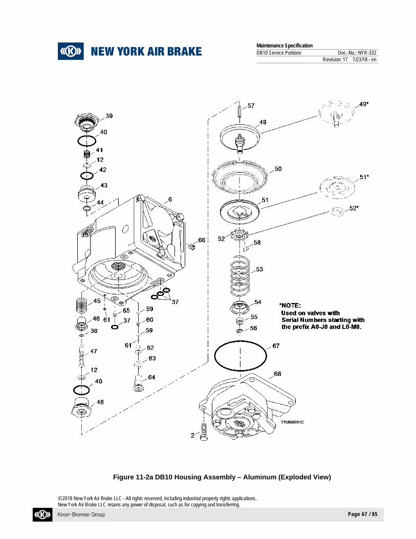
Maintenance Specification DB10 Service Portions Doc.-No.: NYR-332 Revision: 17 7/23/18 - en
© 2018 New York Air Brake LLC - All rights reserved, including industrial property rights applications. New York Air Brake LLC retains any power of disposal, such as for copying and transferring.
Page 67 / 85
Figure 11-2a DB10 Housing Assembly – Aluminum (Exploded View)

Maintenance Specification DB10 Service Portions Doc.-No.: NYR-332 Revision: 17 7/23/18 - en
© 2018 New York Air Brake LLC - All rights reserved, including industrial property rights applications. New York Air Brake LLC retains any power of disposal, such as for copying and transferring.
Page 68 / 85
Figure 11-2b DB10 Housing Assembly – Cast Iron (Exploded View)

Maintenance Specification DB10 Service Portions Doc.-No.: NYR-332 Revision: 17 7/23/18 - en
© 2018 New York Air Brake LLC - All rights reserved, including industrial property rights applications. New York Air Brake LLC retains any power of disposal, such as for copying and transferring.
Page 69 / 85
KEY for FIGURE 11-2a and 11-2b
Item No. Description
2. Hex Head Cap Screw
6. DB10B Housing Assembly
12. Check Valve
37. O-Ring
38. O-Ring
39. Threaded Bushing
40. O-Ring
41. Inlet Valve AR/BC Spring
42. O-Ring
43. Bushing w/Valve Seat
44. K-Ring
45. Quick Service Inlet Valve Spring
46. Spring Guide
47. Stem w/Valve Seat
48. Threaded Bushing
49. Service Main Piston Assembly (4 piece assembly)
50. Service Main Piston Diaphragm
51. Piston Plate
52. Service Main Hex Nut
53. Balancing Spring
54. Service Main Piston Spring Guide
55. Service Main Piston Guide Ring
56. Retaining Ring
57. Stem
58. Key (Fig. 11-2a: N0-XXXXX and higher; also K0-XXXXX)
59. Filter (Replaced by item #64)
60. Stability Choke (Replaced by item #64)
61. O-Ring
62. Stability Choke Housing (Replaced by item #64)

Maintenance Specification DB10 Service Portions Doc.-No.: NYR-332 Revision: 17 7/23/18 - en
© 2018 New York Air Brake LLC - All rights reserved, including industrial property rights applications. New York Air Brake LLC retains any power of disposal, such as for copying and transferring.
Page 70 / 85
Item No. Description
63. Sealing Ring (Replaced by item #64)
64. Weeper Choke Assembly (For P/N I85200/001D, used on portions starting with S/N H0-XXXXX), (For P/N 775868, used on portions starting with S/N G0-XXXXX)
65. Sensitivity Choke
66. BC-Release Choke
67. O-Ring
68. Filler Piece Assembly (DB-10B)
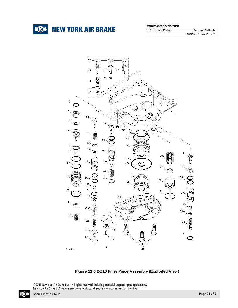
Maintenance Specification DB10 Service Portions Doc.-No.: NYR-332 Revision: 17 7/23/18 - en
© 2018 New York Air Brake LLC - All rights reserved, including industrial property rights applications. New York Air Brake LLC retains any power of disposal, such as for copying and transferring.
Page 71 / 85
Figure 11-3 DB10 Filler Piece Assembly (Exploded View)

Maintenance Specification DB10 Service Portions Doc.-No.: NYR-332 Revision: 17 7/23/18 - en
© 2018 New York Air Brake LLC - All rights reserved, including industrial property rights applications. New York Air Brake LLC retains any power of disposal, such as for copying and transferring.
Page 72 / 85
KEY for FIGURE 11-3
Item No. Description
1 Cover
2 O-Ring
2A O-Ring (Used on portions before S/N D0-XXXXX for P/N I85200/001D)
3 Bushing
4 K-Ring
5 Quick Service Valve Piston
6 K-Ring
7 O-Ring
8 O-Ring
9 Bushing w/Valve Seat and Quick Service Pressure Exhaust Choke
10 O-Ring
11 Check Valve
12 Quick Service Valve Spring
13 Balancing Stem
14 Balancing Valve Spring
15 Washer
16 K-Ring
17 ER Charging Stem
18 AR Charging Stem
19 AR-Charging Valve Sealing Ring
20 Retaining Ring (Used on portions before S/N E0-XXXXX)
21 Bushing (For P/N I85200/001D, used on portions starting with S/N E0-XXXXX); (For P/N 775868, used on portions starting with S/N A0-XXXXX)
22 O-Ring
23 Check Valve
24 Spring Seat [For P/N I85200/001D quantity changed from 1 to 2 starting with S/N E0-XXXXX]; (For P/N 775868, quantity is 2 for all configurations)

Maintenance Specification DB10 Service Portions Doc.-No.: NYR-332 Revision: 17 7/23/18 - en
© 2018 New York Air Brake LLC - All rights reserved, including industrial property rights applications. New York Air Brake LLC retains any power of disposal, such as for copying and transferring.
Page 73 / 85
Item No. Description
25 Balancing Check Valve Spring (For P/N I85200/001D, used on portions starting with E0-XXXXX).
26 Filter (Replaces Bushing w/Exhaust Port for P/N I85200/001D, starting with S/N D0-XXXXX)
27
Bushing (For P/N I85200/001D, used on portions starting with S/N E0-XXXXX); (For P/N 775868, used on portions starting with S/N A0-XXXXX)
28 ER Charging Valve Spring
29 AR Charging Valve Spring
29A Balancing Check Valve Spring (For P/N I85200/001D, Used on portions prior to D0-XXXXX)
30 ER Charging Check Valve Spring
31 ER Charging Check Valve
32 Bushing w/Valve Seat and ER Charging Check Valve Choke
33 O-Ring
34 O-Ring
35 O-Ring
36 O-Ring
37 O-Ring
38 Bushing
39 O-Ring
40 K-Ring
41 Balancing Piston
42 K-Ring
43 Cover Assembly
44 Hex Head Cap Screw
45 Vent Flap
46 Spacer Ring
47 Pop Rivet
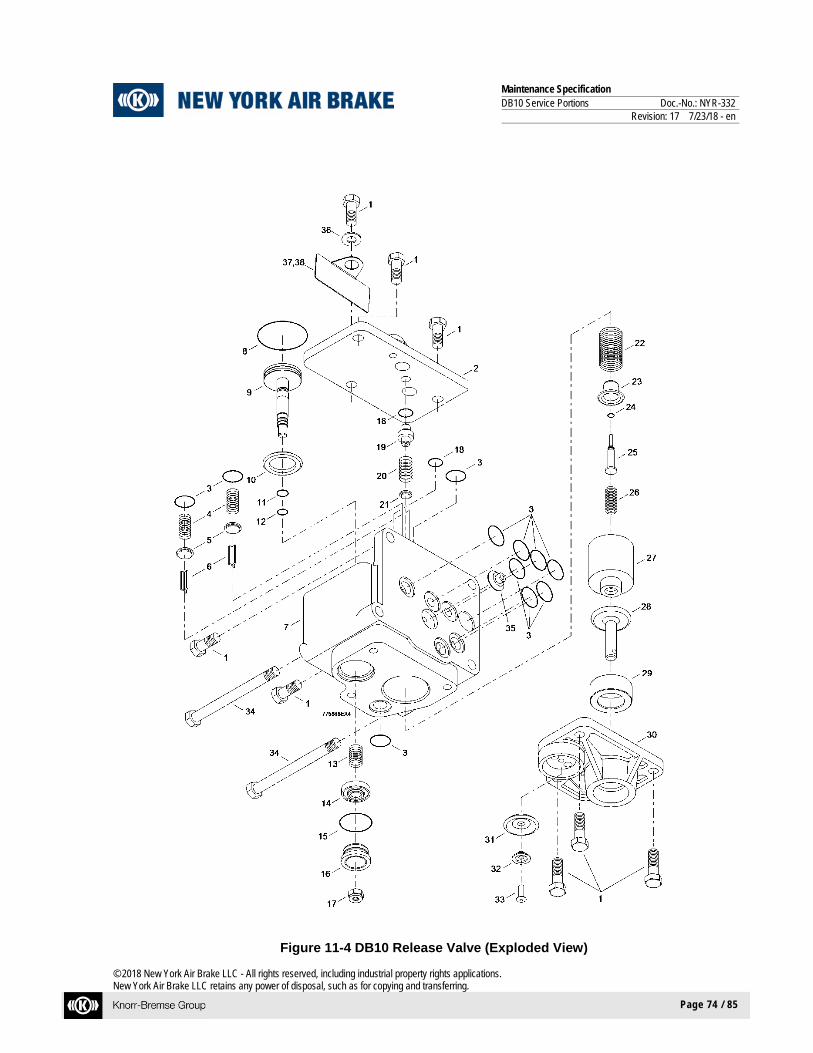
Maintenance Specification DB10 Service Portions Doc.-No.: NYR-332 Revision: 17 7/23/18 - en
© 2018 New York Air Brake LLC - All rights reserved, including industrial property rights applications. New York Air Brake LLC retains any power of disposal, such as for copying and transferring.
Page 74 / 85
Figure 11-4 DB10 Release Valve (Exploded View)

Maintenance Specification DB10 Service Portions Doc.-No.: NYR-332 Revision: 17 7/23/18 - en
© 2018 New York Air Brake LLC - All rights reserved, including industrial property rights applications. New York Air Brake LLC retains any power of disposal, such as for copying and transferring.
Page 75 / 85
KEY for FIGURE 11-4
Item No. Description
1 Hex Head Cap Screw
2 Upper Cover Assembly
3 O-Ring
4 Exhaust Valve Spring
5 Exhaust AR/ER Check Valve
6 Exhaust Valve Stem
7 Release Valve Housing Assembly
8 O-Ring
9 Release Valve Piston
10 K-Ring
11 O-Ring
12 O-Ring
13 Release Valve Portion Spring
14 Release Valve Exhaust Check Valve
15 O-Ring
16 Bushing with Valve Seat
17 Self-Locking Hex Hut
18 O-Ring
19 Bushing w/Valve Seat and Release Valve Charging Control Choke
20 Release Exhaust Check Valve Spring
21 Release Exhaust Check Valve
22 Release Valve Handle Spring
23 Spring Guide
24 O-Ring
25 Release Exhaust Valve Stem
26 Release Exhaust Valve Spring
27 Release Valve Lifter
28 Release Valve Handle
29 Sleeve

Maintenance Specification DB10 Service Portions Doc.-No.: NYR-332 Revision: 17 7/23/18 - en
© 2018 New York Air Brake LLC - All rights reserved, including industrial property rights applications. New York Air Brake LLC retains any power of disposal, such as for copying and transferring.
Page 76 / 85
Item No. Description
30 Lower Cover
31 Vent Flap
32 Spacer Ring
33 Pop Rivet
34 Hex Head Cap Screw
35 Choke
36 Flat Washer
37 CID Tag, AAR
38 CID Label, AAR

Maintenance Specification DB10 Service Portions Doc.-No.: NYR-332 Revision: 17 7/23/18 - en
© 2018 New York Air Brake LLC - All rights reserved, including industrial property rights applications. New York Air Brake LLC retains any power of disposal, such as for copying and transferring.
Page 77 / 85
NOTE
Table 11-1 identifies additional parts that could potentially be replaced at a rate of 100% based on local disassembly/assembly practices.
Table 11-1 Potential 100% Replacement Parts
Fig. No. Item No. Description
11-1 4 Choke, Release Valve Exhaust Control
11-1 16 Spring Guide, Service Accelerated Release Valve
11-1 20 Spring Guide
11-1 36 Choke, Retaining Check Valve
11-2 55 Guide Ring, Service Main Piston
11-3 15 Washer
11-3 17 Stem, ER Charging Valve
11-4 6 Stem, Exhaust Valve
11-4 26 Lifter, Release Valve
11-4 27 Release Valve Handle
11-4 28 Sleeve
11-4 34 Choke, Release Valve Exhaust Control

Maintenance Specification DB10 Service Portions Doc.-No.: NYR-332 Revision: 17 7/23/18 - en
© 2018 New York Air Brake LLC - All rights reserved, including industrial property rights applications. New York Air Brake LLC retains any power of disposal, such as for copying and transferring.
Page 78 / 85
11.2 Special Tools - Drawings (Refer to Figures 11-5 to 11-17)
Figure 11-5 Quick Service Valve Removal Tool (P/N 772615)
Figure 11-6 Quick Service Inlet Valve Positioning Tool (P/N 772616)

Maintenance Specification DB10 Service Portions Doc.-No.: NYR-332 Revision: 17 7/23/18 - en
© 2018 New York Air Brake LLC - All rights reserved, including industrial property rights applications. New York Air Brake LLC retains any power of disposal, such as for copying and transferring.
Page 79 / 85
Figure 11-7 Special Hand Drive Pin (P/N 772617)
Figure 11-8 Retaining Clamp (P/N 772618)
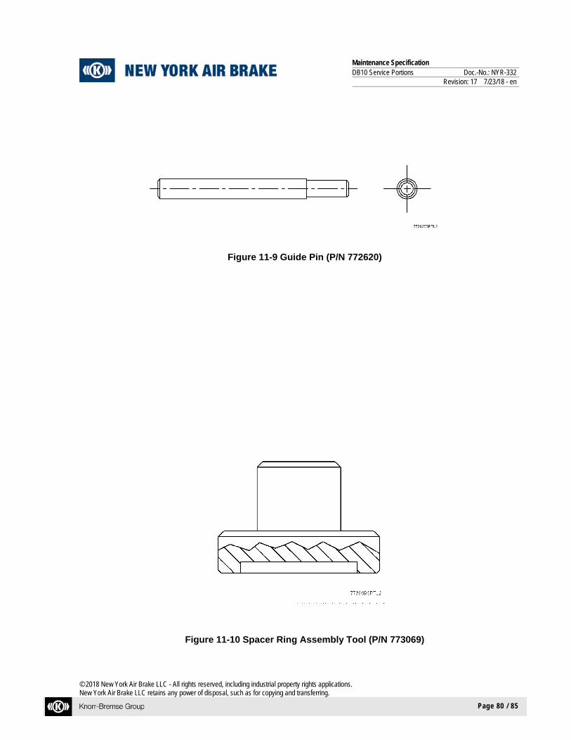
Maintenance Specification DB10 Service Portions Doc.-No.: NYR-332 Revision: 17 7/23/18 - en
© 2018 New York Air Brake LLC - All rights reserved, including industrial property rights applications. New York Air Brake LLC retains any power of disposal, such as for copying and transferring.
Page 80 / 85
Figure 11-9 Guide Pin (P/N 772620)
Figure 11-10 Spacer Ring Assembly Tool (P/N 773069)

Maintenance Specification DB10 Service Portions Doc.-No.: NYR-332 Revision: 17 7/23/18 - en
© 2018 New York Air Brake LLC - All rights reserved, including industrial property rights applications. New York Air Brake LLC retains any power of disposal, such as for copying and transferring.
Page 81 / 85
Figure 11-11 Protection Ring (P/N 772623)
Figure 11-12 Bushing Extractor (P/N 772624)

Maintenance Specification DB10 Service Portions Doc.-No.: NYR-332 Revision: 17 7/23/18 - en
© 2018 New York Air Brake LLC - All rights reserved, including industrial property rights applications. New York Air Brake LLC retains any power of disposal, such as for copying and transferring.
Page 82 / 85
Figure 11-13 Retaining Ring Positioning Tool (P/N 772625)
Figure 11-14 K-Ring Positioning Tool (P/N 772626)
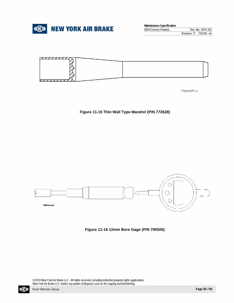
Maintenance Specification DB10 Service Portions Doc.-No.: NYR-332 Revision: 17 7/23/18 - en
© 2018 New York Air Brake LLC - All rights reserved, including industrial property rights applications. New York Air Brake LLC retains any power of disposal, such as for copying and transferring.
Page 83 / 85
Figure 11-15 Thin Wall Type Mandrel (P/N 772628)
Figure 11-16 12mm Bore Gage (P/N 790505)

Maintenance Specification DB10 Service Portions Doc.-No.: NYR-332 Revision: 17 7/23/18 - en
© 2018 New York Air Brake LLC - All rights reserved, including industrial property rights applications. New York Air Brake LLC retains any power of disposal, such as for copying and transferring.
Page 84 / 85
Figure 11-17 17mm Bore Gage (P/N 790506)

Maintenance Specification DB10 Service Portions Doc.-No.: NYR-332 Revision: 17 7/23/18 - en
© 2018 New York Air Brake LLC - All rights reserved, including industrial property rights applications. New York Air Brake LLC retains any power of disposal, such as for copying and transferring.
Page 85 / 85
11.3 Abbreviations and Acronyms
AAR .... .........................ASSOCIATION of AMERICAN RAILROADS ANSI ... .........................AMERICAN NATIONAL STANDARDS INSTITUTE Approx..........................APPROXIMATELY
AR.................................AUXILIARY RESERVOIR
BC.................................BRAKE CYLINDER CCD ... ..........................CAR CONTROL DEVICE CVM ... ..........................CONTROL VALVE MODULE DIA. .... ..........................DIAMETER e.g. ..... ..........................For Example ER ...... ..........................EMERGENCY RESERVOIR ESD .... ..........................ELECTROSTATIC DISCHARGE FCM ... ..........................FUNCTIONAL CONTROL MODULE
Fig ...... ..........................Figure FT-LBS..........................FOOT POUNDS
IN.. ..... ..........................INCH IN-LBS...........................INCH POUNDS LED .... ..........................LIGHT EMITTING DIODE MAX..............................MAXIMUM MIN. ... .........................MINIMUM
MM ..... .........................MILLIMETER No. ..... .........................NUMBER Nm ..... .........................NEWTON METER NYAB . .........................NEW YORK AIR BRAKE PCB .... .........................PRINTED CIRCUIT BOARD PMM ... .........................POWER MANAGEMENT MODULE P/N ..... .........................PART NUMBER POV ... .........................PILOT OPERATED VALVE PSI ..... .........................POUNDS PER SQUARE INCH PSM ... .........................PRESSURE SENSING MODULE QS................................QUICK SERVICE
S/N...............................SERIAL NUMBER