Embed Size (px)
Citation preview
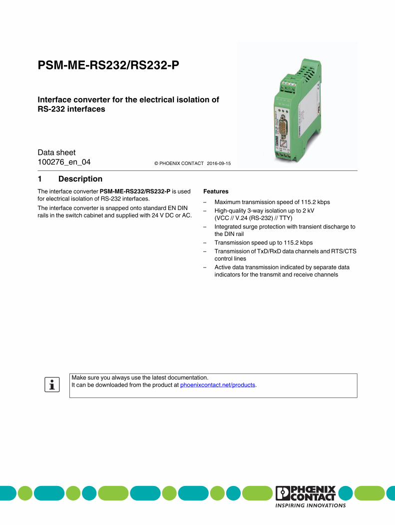
1 Description
Interface converter for the electrical isolation of
RS-232 interfaces
PSM-ME-RS232/RS232-P
© PHOENIX CONTACT
Data sheet
The interface converter PSM-ME-RS232/RS232-P is used
for electrical isolation of RS-232 interfaces.
The interface converter is snapped onto standard EN DIN
rails in the switch cabinet and supplied with 24 V DC or AC.
Features
– Maximum transmission speed of 115.2 kbps
– High-quality 3-way isolation up to 2 kV
(VCC // V.24 (RS-232) // TTY)
– Integrated surge protection with transient discharge to
the DIN rail
– Transmission speed up to 115.2 kbps
– Transmission of TxD/RxD data channels and RTS/CTS
control lines
– Active data transmission indicated by separate data
indicators for the transmit and receive channels
Make sure you always use the latest documentation.
It can be downloaded from the product at phoenixcontact.net/products.
100276_en_04 2016-09-15

PSM-ME-RS232/RS232-P
100276_en_04 PHOENIX CONTACT 2 / 13
2 Table of contents
1 Description .............................................................................................................................. 1
2 Table of contents ..................................................................................................................... 2
3 Ordering data .......................................................................................................................... 3
4 Technical data ......................................................................................................................... 3
5 Safety notes............................................................................................................................. 6
5.1 UL Notes ........................................................................................................................... 6
6 Application examples .............................................................................................................. 7
7 Structure.................................................................................................................................. 8
7.1 Dimensions ........................................................................................................................ 8
7.2 Block diagram..................................................................................................................... 8
7.3 Function elements ............................................................................................................... 9
8 RS-232 interface.................................................................................................................... 10
8.1 DTE/DCE adjustment ......................................................................................................... 11
8.2 COMBICON pin assignment................................................................................................. 12
8.3 Connecting the data cables .................................................................................................. 12
9 Assembly............................................................................................................................... 13
9.1 Removal.......................................................................................................................... 13
9.2 Power supply.................................................................................................................... 13

PSM-ME-RS232/RS232-P
100276_en_04 PHOENIX CONTACT 3 / 13
Description Type Order No. Pcs./Pkt.
Interface converter, for the isolation of RS-232 (V.24)
interfaces, 4 channels, rail-mountable
PSM-ME-RS232/RS232-P 2744461 1
3 Ordering data
Accessories Type Order No. Pcs./Pkt.
RS-232 cable, 9-pos. D-SUB socket 25-pos on D-SUB
socket
PSM-KA 9 SUB 25/BB/
2METER
2761059 1
RS-232 cable, 9-pos. D-SUB socket on 9-pos. D-SUB
socket, 9-wire, 1:1
PSM-KA9SUB9/BB/2METER 2799474 1
Shield connection clip for printed circuit terminal block ME-SAS 2853899 10
Actuation tool, for ST terminal blocks, also suitable for use
as a bladed screwdriver, size: 0.6 x 3.5 x 100 mm,
2-component grip, with non-slip grip
SZF 1-0,6X3,5 1204517 10
4 Technical data
Supply
Supply voltage range 19.2 V AC/DC ... 28.8 V AC/DC
Nominal supply voltage 24 V AC/DC ±20 %
Typical current consumption 40 mA (24 V DC)
Protective circuit Surge protection (Suppressor diode)
Electrical isolation VCC // V.24 (RS-232) (A) // V.24 (RS-232) (B)
Test voltage data interface/power supply 2 kVrms (50 Hz, 1 min.)
Torque 0.56 Nm ... 0.79 Nm
V.24 (RS-232) interface in acc. with ITU-T V.28, EIA/TIA-232, DIN 66259-1
Transmission channels 4 (2/2), RxD, TxD, RTS, CTS; full duplex
Connection method D-SUB 9 plug
Conductor cross section 0.2 mm² ... 2.5 mm² (24 AWG ... 13 AWG)
Serial transmission speed 115.2 kbps
Transmission length 15 m (shielded twisted pair)
Protocols supported transparent protocol
Pin assignment DTE/DCE switchover via switch

PSM-ME-RS232/RS232-P
100276_en_04 PHOENIX CONTACT 4 / 13
V.24 (RS-232) interface in acc. with ITU-T V.28, EIA/TIA-232, DIN 66259-1
Connection method Pluggable screw connection
Transmission length 15 m (shielded twisted pair)
General data
Degree of protection IP20
Dimensions (W/H/D) 22.5 mm x 99 mm x 118.6 mm
Housing material PA green
Bit distortion < 5 %
Bit delay < 3 µs
Noise emission according to EN 61000-6-3
Noise immunity according to EN 61000-6-2:2005
Electromagnetic compatibility Conformance with EMC Directive 2014/30/EU
Transmission channels 4 (2/2), RxD, TxD, RTS, CTS; full duplex
Ambient conditions
Ambient temperature (operation) 0 °C ... 55 °C
Ambient temperature (storage/transport) -40 °C ... 85 °C
Permissible humidity (operation) 10 % ... 95 % (non-condensing)
Altitude 5000 m (For restrictions see manufacturer's declaration)
Approvals / Certificates
Conformance CE-compliant
EAC
UL, USA/Canada 508 recognized
Class I, Div. 2, Groups A, B, C, D
Class I, Zone 2, AEx nA IIC T4
Class I, Zone 2, Ex nA IIC T4 Gc X
Shipbuilding approval DNV

PSM-ME-RS232/RS232-P
100276_en_04 PHOENIX CONTACT 5 / 13
Conformance with EMC Directive 2014/30/EU
Noise immunity according to EN 61000-6-2
Electrostatic discharge EN 61000-4-2
Contact
discharge
± 6 kV (Test Level 3)
Discharge in air ± 8 kV (Test Level 3)
Comments Criterion B
Electromagnetic HF field EN 61000-4-3
Frequency range Test Level 3
Field intensity 10 V/m
Comments Criterion A
Fast transients (burst) EN 61000-4-4
Input ± 4 kV (5 kHz)
Signal ± 2 kV (5 kHz)
Comments Criterion B
Surge current loads (surge) EN 61000-4-5
Input ± 0.5 kV (2 Ω)
Signal ± 2 kV (12 Ω)
Comments Criterion B
Conducted interference EN 61000-4-6
Voltage 10 V
Comments Criterion A
Emitted interference in acc. with EN 61000-6-4
Interference emission EN 55011
Class A, industrial applications
Criterion A Normal operating behavior within the specified limits
Criterion B Temporary impairment of operating behavior that is corrected by the device itself

PSM-ME-RS232/RS232-P
100276_en_04 PHOENIX CONTACT 6 / 13
5 Safety notes
• Installation, operation, and maintenance may only be
carried out by qualified electricians. Follow the
installation instructions as described.
• When installing and operating the device, the
applicable regulations and safety directives (including
national safety directives), as well as general technical
regulations, must be observed. The technical data is
provided in the package slip and on the certificates
(conformity assessment, additional approvals where
applicable).
• Changing or modifying the device beyond the
configuration is not permitted. Do not repair the device
yourself; replace it with an equivalent device. Repairs
may only be performed by the manufacturer. The
manufacturer is not liable for damage resulting from
noncompliance.
• The IP20 protection (IEC 60529/EN 60529) of the
device is intended for use in a clean and dry
environment. The device must not be subject to
mechanical strain and/or thermal loads, which exceed
the limits described.
• The switches of the device that can be accessed may
only be actuated when the power supply to the device is
disconnected.
• The device is designed exclusively for SELV operation
according to IEC 60950/EN 60950/VDE 0805. The
device may only be connected to devices, which meet
the requirements of EN 60950.
5.1 UL Notes
WARNING:
Observe the following safety notes when
using the device.
PROCESS CONTROL EQUIPMENT FOR HAZARDOUS LOCATIONS 31ZN
A)
B)
C)
D)
All wiring of these devices must be in accordance with the national electric code article
501.4(B) for Class 1, Division 2.
Product must be installed in Class I, Zone 2 certified at least an IP54 enclosure.
Product must be used in no more than a pollution degree 2 environment as defined by IEC 60664-1
Provisions must be made to provide transient protection to the product so that
voltage levels do not exceed 40% of the rated voltage at the power supply terminals.
Wire Range: 30-12 AWG,
Torque: 5-7 Lbs-Ins
Supply voltage range 24 V DC 20% 85 mA

PSM-ME-RS232/RS232-P
100276_en_04 PHOENIX CONTACT 7 / 13
6 Application examples
The RS-232 interface is an asymmetric voltage interface
with common signal ground for all signals. In addition to its
very low signal power, a characteristic feature of the
interface is that the signal ground is connected to the
grounded chassis housing. This results in very little
immunity to interference and a maximum range of
15 meters. Considerably higher immunity to interference is
achieved in industrial applications with the interface
converter for electrical isolation.
Interference-free RS-232 interface
Figure 1 Interference-free RS-232 interface
With their high-grade 3-way isolation between both interface
sides the devices provide a floating and interference-
resistant RS-232 interface for the supply and ground
potential.
Expensive termination devices are protected against
damage by this decoupling.
Electrical isolation
Figure 2 Electrical isolation
Any potential references can be removed from the
transmission path by using additional isolator modules on
both device interfaces.
RS232
RS232
TXD RXD CTSRTS
GND 6
1 2
3 4
5
6 7
8 9
24v 24V 0V 0V
PS
M–M
E–R
S2
32
/RS
23
2–P
Ord
.-N
o.:
2
74
4 4
61
RS-23215 m≤
RS-23215 m≤
RS-23215 m≤
RS-23215 m≤
RS232
RS232
TXD RXD CTSRTS
GND 6
1 2
3 4
5
6 7
8 9
24v 24V 0V 0V
PS
M–M
E–R
S2
32
/RS
23
2–P
Ord
.-N
o.:
2
74
4 4
61
RS232
RS232
TXD RXD CTSRTS
GND 6
1 2
3 4
5
6 7
8 9
24v 24V 0V 0V
PS
M–M
E–R
S2
32
/RS
23
2–P
Ord
.-N
o.:
2
74
4 4
61
RS-23215 m≤

PSM-ME-RS232/RS232-P
100276_en_04 PHOENIX CONTACT 8 / 13
7 Structure
7.1 Dimensions
Figure 3 Housing dimensions
7.2 Block diagram
Figure 4 Block diagram
112
118,6
22,5
99
PS
M-M
E-R
S2
32
/RS
48
5-P
Ord
.-N
o.:
27
44
41
6
D(A) D(B) T(A) T(B)
GND
RS232
RS485

PSM-ME-RS232/RS232-P
100276_en_04 PHOENIX CONTACT 9 / 13
7.3 Function elements
Figure 5 Function elements
COMBICON plug-in screw terminal blocks
1 Supply voltage
6 RS-232 (B) RS-232 interface
Operating elements
5 RS-232 (A) D-SUB 9-pos. (pin) RS-232 interface
7 Shield connection clip
8 Locking latch for DIN rail mounting
Diagnostics and status indicators
2 VCC (green) Supply voltage
3 RD (green) RS-232 (A) Receive data, dynamic
4 TD (yellow) RS-232 (A) Transmit data, dynamic
PSM-ME-
Ord
.-No.:
1234
5
6
7
8

PSM-ME-RS232/RS232-P
100276_en_04 PHOENIX CONTACT 10 / 13
8 RS-232 interface
Figure 6 RS-232 interface (A)
Figure 7 RS-232 interface (B)
Create a 1:1 connection between the PSM module's RS-232
interface and the peripheral.
Note: The minimum configuration only requires one
connection for TxD, RxD and GND (software handshake)!
• Plug the 9-pos. D-SUB connector onto the device.
Peripherals side
D-SUB
4
6
5
3
2
8
7
DTR
DSR
GND
TxD
RxD
CTS
RTS
3
2
8
7
4
6
5
2
3
5
4
20
6
7
DTR
DSR
GND
TxD
RxD
CTS
RTS
925
Shield
PSM-ME-RS232...
RS-232 (A)
PSM-ME-RS232...
RS-232 (B)
Peripherals side
D-SUB
COMBICONMINICONNEC
-
-
6
8
1
2
4
3
DTR
DSR
GND
TxD
RxD
CTS
RTS
3
2
8
7
5
2
3
5
4
7 GND
TxD
RxD
CTS
RTS
925
Shield
Pin D-SUB 9
(A)
Designation
3 TxD Transmit data
2 RxD Receive data
8 CTS Clear to send
7 RTS Request to send
5 GND Operating ground
4 DTR DTE ready
6 DSR Ready to operate
Shield Shield connection

PSM-ME-RS232/RS232-P
100276_en_04 PHOENIX CONTACT 11 / 13
8.1 DTE/DCE adjustment
The TxD and RxD as well as the RTS and CTS cables can
be crossed internally using a DTE/DCE slide switch so that
you are able to conveniently adapt to DTE or DCE
interfaces.
You must open the housing to access the slide switch.
• Disengage the housing cover with a screwdriver (A).
• Carefully pull the PCB out of the housing as far as
possible.
Figure 8 Opening the housing
Figure 9 Remove the PCB
When connecting to a DTE device (Data Terminal
Equipment), slide the switch to the DTE position.
When connecting to a DCE device (Data Communication
Equipment) slide the switch to the DCE position.
The DSR/DTR control lines are permanently bridged
internally!
NOTE: electrostatic discharge!
The device contains components that can be
damaged or destroyed by electrostatic
discharge. When handling the device,
observe the necessary safety precautions
against electrostatic discharge (ESD)
according to EN 61340-5-1 and
IEC 61340-5-1.
If the connected interface type is not known,
you can determine the right configuration by
testing the S1 DTE /DCE-slide switch.

PSM-ME-RS232/RS232-P
100276_en_04 PHOENIX CONTACT 12 / 13
8.2 COMBICON pin assignment
Interface adaptation
On the field side, you can adapt the interface converter to
DTE or DCE devices at the COMBICON plug-in screw
terminal blocks.
DTE
– When connecting to a DTE device (standard for the
majority of applications), cross the TXD/RXD and
RTS/CTS cables.
Figure 10 Connection to a DTE device
DCE
– When connecting to a DCE device, connect the devices
1:1.
Figure 11 Connection to a DCE device
You can use the diagnostic LEDs to track the
communication setup. The indicators always relate to the
data traffic at the D-SUB interface.
8.3 Connecting the data cables
• For the shield connection, use the provided shield
connection clip.
Figure 12 Install shield clip
Pin COMBICON (B) Designation
1 TxD Transmit data
2 RxD Receive data
3 RTS Request to send
4 CTS Clear to send
6 GND Operating ground
8 Shield connection
If you do not know which type of interface is
connected, you can determine the right
configuration by trial and error.
NOTE: Interference
Use shielded twisted pair data cables.
Connect the cable shielding at both ends of
the transmission path.

PSM-ME-RS232/RS232-P
100276_en_04 13 / 13PHOENIX CONTACT GmbH & Co. KG • 32823 Blomberg • Germany
phoenixcontact.com
9 Assembly
Figure 13 Mounting on a DIN rail
• To avoid contact resistance, only use clean, corrosion-
free 35 mm DIN rails according to DIN EN 60715.
• Install an end bracket next to the left-hand device to
prevent the devices from slipping.
• Place the device onto the DIN rail from above. Push the
module from the front toward the mounting surface until
it audibly engages.
9.1 Removal
Figure 14 Removal
• Push down the locking tab with a screwdriver, needle-
nose pliers or similar.
• Slightly pull the bottom edge of the device away from
the mounting surface.
• Pull the device away from the DIN rail.
9.2 Power supply
The device is supplied with 24 V DC or AC.
Figure 15 Power supply
• Provide supply voltage to the device via terminal 1
(pin 1 and pin 3).
CAUTION: Electric shock
The device is only intended for operation with
SELV according to IEC 60950/EN 60950/
VDE 0805.
NOTE: Malfunction
Connect the DIN rail to protective earth
ground using a grounding terminal block. The
device is grounded when it is snapped onto
the DIN rail.
This ensures the integrated surge protection
is functional and that the shielding of the data
cable is effective.
A
B
PSM-ME-
5
24V24V 0V
0V
TXD RXD CTSRTS
GND
1 2
3 4
5
6 7
8 9
24V 24V 0V 0V
PS
M-M
E-
Ord
.-N
o.: