Embed Size (px)
Citation preview
A
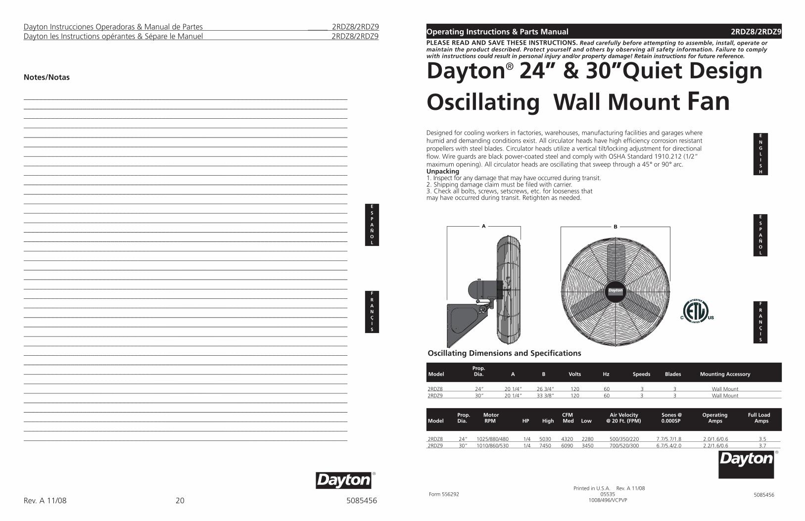
Designed for cooling workers in factories, warehouses, manufacturing facilities and garages where humid and demanding conditions exist. All circulator heads have high efficiency corrosion resistant propellers with steel blades. Circulator heads utilize a vertical tilt/locking adjustment for directional flow. Wire guards are black power-coated steel and comply with OSHA Standard 1910.212 (1/2” maximum opening). All circulator heads are oscillating that sweep through a 45° or 90° arc.
2Operating Instructions & Parts Manual 2RDZ8/2RDZ9
Dayton® 24” & 30”Quiet Design Oscillating Wall Mount Fan
Unpacking1. Inspect for any damage that may have occurred during transit.2. Shipping damage claim must be filed with carrier.3. Check all bolts, screws, setscrews, etc. for looseness that may have occurred during transit. Retighten as needed.
ENG L I S H
ESP A Ñ O L
FRAN ÇI S
Oscillating Dimensions and Specifications
2RDZ8 24” 20 1/4” 26 3/4” 120 60 3 3 Wall Mount 2RDZ9 30” 20 1/4” 33 3/8” 120 60 3 3 Wall Mount
2 Prop. Model Dia. A B Volts Hz Speeds Blades Mounting Accessory
2RDZ8 24” 1025/880/480 1/4 5030 4320 2280 500/350/220 7.7/5.7/1.8 2.0/1.6/0.6 3.5 2RDZ9 30” 1010/860/530 1/4 7450 6090 3450 700/520/300 6.7/5.4/2.0 2.2/1.6/0.6 3.7
Prop. Motor CFM Air Velocity Sones @ Operating Full Load Model Dia. RPM HP High Med Low @ 20 Ft. (FPM) 0.000SP Amps Amps
PLEASE READ AND SAVE tHESE INStRUCtIONS. Read carefully before attempting to assemble, install, operate or maintain the product described. Protect yourself and others by observing all safety information. Failure to comply with instructions could result in personal injury and/or property damage! Retain instructions for future reference.
Form 5S6292 Printed in U.S.A. Rev. A 11/08
055351008/496/VCPVP
5085456
Dayton Instrucciones Operadoras & Manual de Partes _____ 2RDZ8/2RDZ9Dayton les Instructions opérantes & Sépare le Manuel 2RDZ8/2RDZ9
Notes/Notas
__________________________________________________________________________________________________________________________________________________________________________________________________________________________________________________________________________________________________________________________________________________________________________________________________________________________________________________________________________________________________________________________________________________________________________________________________________________________________________________________________________________________________________________________________________________________________________________________________________________________________________________________________________________________________________________________________________________________________________________________________________________________________________________________________________________________________________________________________________________________________________________________________________________________________________________________________________________________________________________________________________________________________________________________________________________________________________________________________________________________________________________________________________________________________________________________________________________________________________________________________________________________________________________________________________________________________________________________________________________________________________________________________________________________________________________________________________________________________________________________________________________________________________________________________________________________________________________________________________________________________________________________________________________________________________________________________________________________________________________________________________________________________________________________________________________________________________________________________________________________________________________________________________________________________________________________________________________________________________________________________________________________________________________________________________________________________________________________________________________________________________________________________________________________________________________________________________________________________________________________________________________________________________________________________________________________________________________________________________________________
ESP A Ñ O L
FRAN ÇI S
20Rev. A 11/08 5085456
GENERAL SAFEtY INFORMAtIONWhen using electrical appliances, basic precautions should always be followed to reduce the risk of fire, electric shock and injury to person, including the following:
Dayton® 24” & 30”Quiet Design Oscillating Wall Mount Fan
1. Read all instructions before using Fan. 2. Make certain that the power source con-
forms to the electrical requirements of the Fan.
3. Use this Fan only as described in this manual. Any other use not recommended by the manufacturer may cause fire, electrical shock, or injury to persons.
4. To reduce the risk of personal injury and elec-tric shock, the Fan should not be played with or placed where small children can reach it.
5. Unplug power cord before servicing, or moving the Fan.
WARNING: DO NOt DEPEND UPON tHE ON-OFF SWItCH AS tHE SOLE MEANS OF DISCONNECtING POWER WHEN INStALLING OR SERVICING tHE FAN. ALWAYS UNPLUG tHE POWER CORD.6. This Fan must NOT be used in potentially
dangerous locations such as flammable, explosive, chemical-laden or wet atmo-spheres.
7. DO NOT use Fan in or near a window. Rain may create an electrical hazard.
8. Completely reassemble Fan, according to instructions, before reconnecting to power supply.
9. The power cord is equipped with a three-prong grounded plug that should be inserted into a matching receptacle. Under no circumstances should the grounding prong be cut off the plug. Where a two-prong wall receptacle is encountered, it must be replaced with a properly grounded three-prong receptacle installed in accordance with the National Electrical Code (NEC) and all applicable local codes and ordinances. This work must be done only by a qualified electrician, using copper wire only.
GENERAL SAFEtY INFORMAtIONWhen using electrical appli-ances, basic precautions should always be followed to reduce the risk of fire, electric shock and injury to person, including the following:
WARNING: USE OF A tHREE-PRONG tO tWO-PRONG ADAPtER IS NOt REC-OMMENDED. IMPROPER CONNECtION MAY CREAtE tHE RISK OF ELECtRICAL SHOCK. USE OF SUCH ADAPtERS IS NOt PERMIttED IN CANADA.10. Where possible, avoid the use of
extension cords. If they must be used, minimize the risk of overheating by ensuring that they are UL listed. Never use a single extension cord to operate more than one Fan. Do not plug Fan into any other cord connected device, such as a power strip, cord reel, surge protector, multiple outlet adapters or outlet-type air fresheners. The use of such devices may create a fire hazard.
11. Do not operate any Fan with a damaged cord or plug or after the Fan malfunctions, has been dropped or damaged in any manner. Return Fan to authorized service facility for examination, electrical or mechanical adjustment or repair.
12. Do not insert or allow fingers or foreign objects to enter any ventilation or exhaust opening as it may cause an electric shock or fire, or damage the Fan. Do not block or tamper with the Fan in any manner while it is in operation.
13.Locate the Power Cord so the Fan or other objects are not resting on it. Do not run Power Cord under carpeting or floor mats. Do not cover Power Cord with runners, or the like. Do not run Power Cord through doorways, windows or areas where cord impingement may occur. Arrange Power Cord away from room traffic and where it will not be tripped over.
14.This Fan is not intended for use in wet or damp locations. Never locate a Fan where it may fall into water.
15. Do not use Fan outdoors.16.This Fan is not suitable for use in
hazardous locations. Please refer to National Electric Code (NEC) Article
500 or applicable state or local codes or standards relating to electrical requirements for Hazardous locations. tHIS FAN DOES NOt MEEt tHE REQUIREMENtS OF NEC ARtICLE 500 (2008).
WARNING: REDUCE tHE RISK OF FIRE OR ELECtRIC SHOCK – DO NOt USE tHIS FAN WItH ANY SOLID StAtE SPEED CONtROL DEVICES.CAUtION: BECAUSE OF tHE SIZE AND WEIGHt OF tHIS FAN, MAKE SURE ALL PARtS ARE COMPLEtELY ASSEMBLED ACCORDING tO INStRUCtIONS. FAILURE tO DO SO COULD RESULt IN FAN COMING APARt DURING OPERAtION AND/OR PERSONAL INJURY.
Dayton Operating Instructions & Parts Manual 2RDZ8/2RDZ9
Rev. A 11/08 50854562
Dayton Operating Instructions & Parts Manual 2RDZ8/2RDZ9Notes
__________________________________________________________________________________________________________________________________________________________________________________________________________________________________________________________________________________________________________________________________________________________________________________________________________________________________________________________________________________________________________________________________________________________________________________________________________________________________________________________________________________________________________________________________________________________________________________________________________________________________________________________________________________________________________________________________________________________________________________________________________________________________________________________________________________________________________________________________________________________________________________________________________________________________________________________________________________________________________________________________________________________________________________________________________________________________________________________________________________________________________________________________________________________________________________________________________________________________________________________________________________________________________________________________________________________________________________________________________________________________________________________________________________________________________________________________________________________________________________________________________________________________________________________________________________________________________________________________________________________________________________________________________________________________________________________________________________________________________________________________________________________________________________________________________________________________________________________________________________________________________________________________________________________________________________________________________________________________________________________________________________________________________________________________________________________________________________________________________________________________________________________________________________________________________________________________________________________________________________________________________________________________________________________________________________________________________________________________________________________
ENG L I S H
19Rev. A 11/08 5085456
3
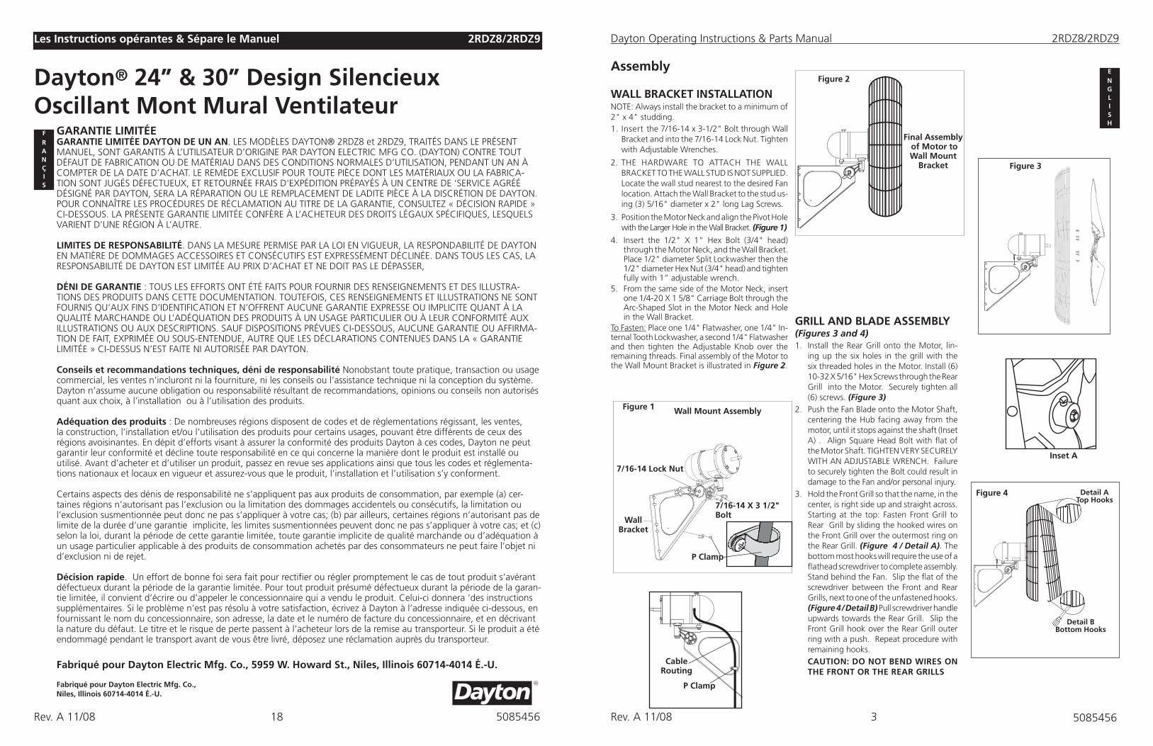
GRILL AND BLADE ASSEMBLY (Figures 3 and 4)1. Install the Rear Grill onto the Motor, lin-
ing up the six holes in the grill with the six threaded holes in the Motor. Install (6) 10-32 X 5/16" Hex Screws through the Rear Grill into the Motor. Securely tighten all (6) screws. (Figure 3)
2. Push the Fan Blade onto the Motor Shaft, centering the Hub facing away from the motor, until it stops against the shaft (Inset A) . Align Square Head Bolt with flat of the Motor Shaft. TIGHTEN VERY SECURELY WITH AN ADJUSTABLE WRENCH. Failure to securely tighten the Bolt could result in damage to the Fan and/or personal injury.
3. Hold the Front Grill so that the name, in the center, is right side up and straight across. Starting at the top: Fasten Front Grill to Rear Grill by sliding the hooked wires on the Front Grill over the outermost ring on the Rear Grill. (Figure 4 / Detail A). The bottom most hooks will require the use of a flathead screwdriver to complete assembly. Stand behind the Fan. Slip the flat of the screwdriver between the Front and Rear Grills, next to one of the unfastened hooks. (Figure 4 / Detail B) Pull screwdriver handle upwards towards the Rear Grill. Slip the Front Grill hook over the Rear Grill outer ring with a push. Repeat procedure with remaining hooks.
CAUtION: DO NOt BEND WIRES ON tHE FRONt OR tHE REAR GRILLS
Assembly
WALL BRACKEt INStALLAtIONNOTE: Always install the bracket to a minimum of 2" x 4" studding.1. Insert the 7/16-14 x 3-1/2" Bolt through Wall
Bracket and into the 7/16-14 Lock Nut. Tighten with Adjustable Wrenches.
2. THE HARDWARE TO ATTACH THE WALL BRACKET TO THE WALL STUD IS NOT SUPPLIED. Locate the wall stud nearest to the desired Fan location. Attach the Wall Bracket to the stud us-ing (3) 5/16" diameter x 2" long Lag Screws.
3. Position the Motor Neck and align the Pivot Hole with the Larger Hole in the Wall Bracket. (Figure 1)
4. Insert the 1/2" X 1" Hex Bolt (3/4" head) through the Motor Neck, and the Wall Bracket. Place 1/2" diameter Split Lockwasher then the 1/2" diameter Hex Nut (3/4" head) and tighten fully with 1” adjustable wrench.
5. From the same side of the Motor Neck, insert one 1/4-20 X 1 5/8" Carriage Bolt through the Arc-Shaped Slot in the Motor Neck and Hole in the Wall Bracket.
To Fasten: Place one 1/4" Flatwasher, one 1/4" In-ternal Tooth Lockwasher, a second 1/4" Flatwasher and then tighten the Adjustable Knob over the remaining threads. Final assembly of the Motor to the Wall Mount Bracket is illustrated in Figure 2.
Figure 2
Final Assembly of Motor toWall Mount
Bracket
Wall Mount Assembly
Figure 3
Inset A
Detail BBottom Hooks
Detail Atop Hooks
Figure 4
Figure 1
Wall Bracket
7/16-14 X 3 1/2" Bolt
7/16-14 Lock Nut
P Clamp
P Clamp
CableRouting
Dayton Operating Instructions & Parts Manual 2RDZ8/2RDZ9
Rev. A 11/08 5085456
ENG L I S H
GARANtIE LIMItÉEGARANtIE LIMItÉE DAYtON DE UN AN. LES MODÈLES DAYTON® 2RDZ8 et 2RDZ9, TRAITÉS DANS LE PRÉSENT MANUEL, SONT GARANTIS À L’UTILISATEUR D’ORIGINE PAR DAYTON ELECTRIC MFG CO. (DAYTON) CONTRE TOUT DÉFAUT DE FABRICATION OU DE MATÉRIAU DANS DES CONDITIONS NORMALES D’UTILISATION, PENDANT UN AN À COMPTER DE LA DATE D’ACHAT. LE REMÈDE EXCLUSIF POUR TOUTE PIÈCE DONT LES MATÉRIAUX OU LA FABRICA-TION SONT JUGÉS DÉFECTUEUX, ET RETOURNÉE FRAIS D'EXPÉDITION PRÉPAYÉS À UN CENTRE DE ‘SERVICE AGRÉÉ DÉSIGNÉ PAR DAYTON, SERA LA RÉPARATION OU LE REMPLACEMENT DE LADITE PIÈCE À LA DISCRÉTION DE DAYTON. POUR CONNAÎTRE LES PROCÉDURES DE RÉCLAMATION AU TITRE DE LA GARANTIE, CONSULTEZ « DÉCISION RAPIDE » CI-DESSOUS. LA PRÉSENTE GARANTIE LIMITÉE CONFÈRE À L’ACHETEUR DES DROITS LÉGAUX SPÉCIFIQUES, LESQUELS VARIENT D’UNE RÉGION À L’AUTRE.
LIMItES DE RESPONSABILItÉ. DANS LA MESURE PERMISE PAR LA LOI EN VIGUEUR, LA RESPONDABILITÉ DE DAYTON EN MATIÈRE DE DOMMAGES ACCESSOIRES ET CONSÉCUTIFS EST EXPRESSÉMENT DÉCLINÉE. DANS TOUS LES CAS, LA RESPONSABILITÉ DE DAYTON EST LIMITÉE AU PRIX D’ACHAT ET NE DOIT PAS LE DÉPASSER,
DÉNI DE GARANtIE : TOUS LES EFFORTS ONT ÉTÉ FAITS POUR FOURNIR DES RENSEIGNEMENTS ET DES ILLUSTRA-TIONS DES PRODUITS DANS CETTE DOCUMENTATION. TOUTEFOIS, CES RENSEIGNEMENTS ET ILLUSTRATIONS NE SONT FOURNIS QU’AUX FINS D’IDENTIFICATION ET N’OFFRENT AUCUNE GARANTIE EXPRESSE OU IMPLICITE QUANT À LA QUALITÉ MARCHANDE OU L’ADÉQUATION DES PRODUITS À UN USAGE PARTICULIER OU À LEUR CONFORMITÉ AUX ILLUSTRATIONS OU AUX DESCRIPTIONS. SAUF DISPOSITIONS PRÉVUES CI-DESSOUS, AUCUNE GARANTIE OU AFFIRMA-TION DE FAIT, EXPRIMÉE OU SOUS-ENTENDUE, AUTRE QUE LES DÉCLARATIONS CONTENUES DANS LA « GARANTIE LIMITÉE » CI-DESSUS N’EST FAITE NI AUTORISÉE PAR DAYTON.
Conseils et recommandations techniques, déni de responsabilité Nonobstant toute pratique, transaction ou usage commercial, les ventes n’incluront ni la fourniture, ni les conseils ou l’assistance technique ni la conception du système. Dayton n’assume aucune obligation ou responsabilité résultant de recommandations, opinions ou conseils non autorisés quant aux choix, à l’installation ou à l’utilisation des produits.
Adéquation des produits : De nombreuses régions disposent de codes et de réglementations régissant, les ventes, la construction, l’installation et/ou l’utilisation des produits pour certains usages, pouvant être différents de ceux des régions avoisinantes. En dépit d’efforts visant à assurer la conformité des produits Dayton à ces codes, Dayton ne peut garantir leur conformité et décline toute responsabilité en ce qui concerne la manière dont le produit est installé ou utilisé. Avant d’acheter et d’utiliser un produit, passez en revue ses applications ainsi que tous les codes et réglementa-tions nationaux et locaux en vigueur et assurez-vous que le produit, l’installation et l’utilisation s’y conforment.
Certains aspects des dénis de responsabilité ne s’appliquent pas aux produits de consommation, par exemple (a) cer-taines régions n’autorisant pas l’exclusion ou la limitation des dommages accidentels ou consécutifs, la limitation ou l’exclusion susmentionnée peut donc ne pas s’appliquer à votre cas; (b) par ailleurs, certaines régions n’autorisant pas de limite de la durée d’une garantie implicite, les limites susmentionnées peuvent donc ne pas s’appliquer à votre cas; et (c) selon la loi, durant la période de cette garantie limitée, toute garantie implicite de qualité marchande ou d’adéquation à un usage particulier applicable à des produits de consommation achetés par des consommateurs ne peut faire l’objet ni d’exclusion ni de rejet.
Décision rapide. Un effort de bonne foi sera fait pour rectifier ou régler promptement le cas de tout produit s’avérant défectueux durant la période de la garantie limitée. Pour tout produit présumé défectueux durant la période de la garan-tie limitée, il convient d’écrire ou d’appeler le concessionnaire qui a vendu le produit. Celui-ci donnera ‘des instructions supplémentaires. Si le problème n’est pas résolu à votre satisfaction, écrivez à Dayton à l’adresse indiquée ci-dessous, en fournissant le nom du concessionnaire, son adresse, la date et le numéro de facture du concessionnaire, et en décrivant la nature du défaut. Le titre et le risque de perte passent à l’acheteur lors de la remise au transporteur. Si le produit a été endommagé pendant le transport avant de vous être livré, déposez une réclamation auprès du transporteur.
Fabriqué pour Dayton Electric Mfg. Co., 5959 W. Howard St., Niles, Illinois 60714-4014 É.-U.
Fabriqué pour Dayton Electric Mfg. Co., Niles, Illinois 60714-4014 É.-U.
FRAN ÇI S
Dayton® 24” & 30” Design Silencieux Oscillant Mont Mural Ventilateur
2Les Instructions opérantes & Sépare le Manuel 2RDZ8/2RDZ9
18Rev. A 11/08 5085456
OPERAtING INStRUCtIONS1. TO OPERATE: Plug cord into a grounded
120V, 60 Hz outlet. Select desired operating speed with pull cord on the rear of the motor:
First pull: High Second pull: Medium Third pull: Low Fourth pull: OFF
NOTE: THIS FAN IS VERY HEAVY. Failure to securely hold onto head assembly
while adjusting head angle could result in personal injury.
2. TO ADJUST HEAD ANGLE: While holding head firmly, loosen knob under motor (turn counterclockwise). Tilt head to desired position FIRMLY retighten knob under motor.
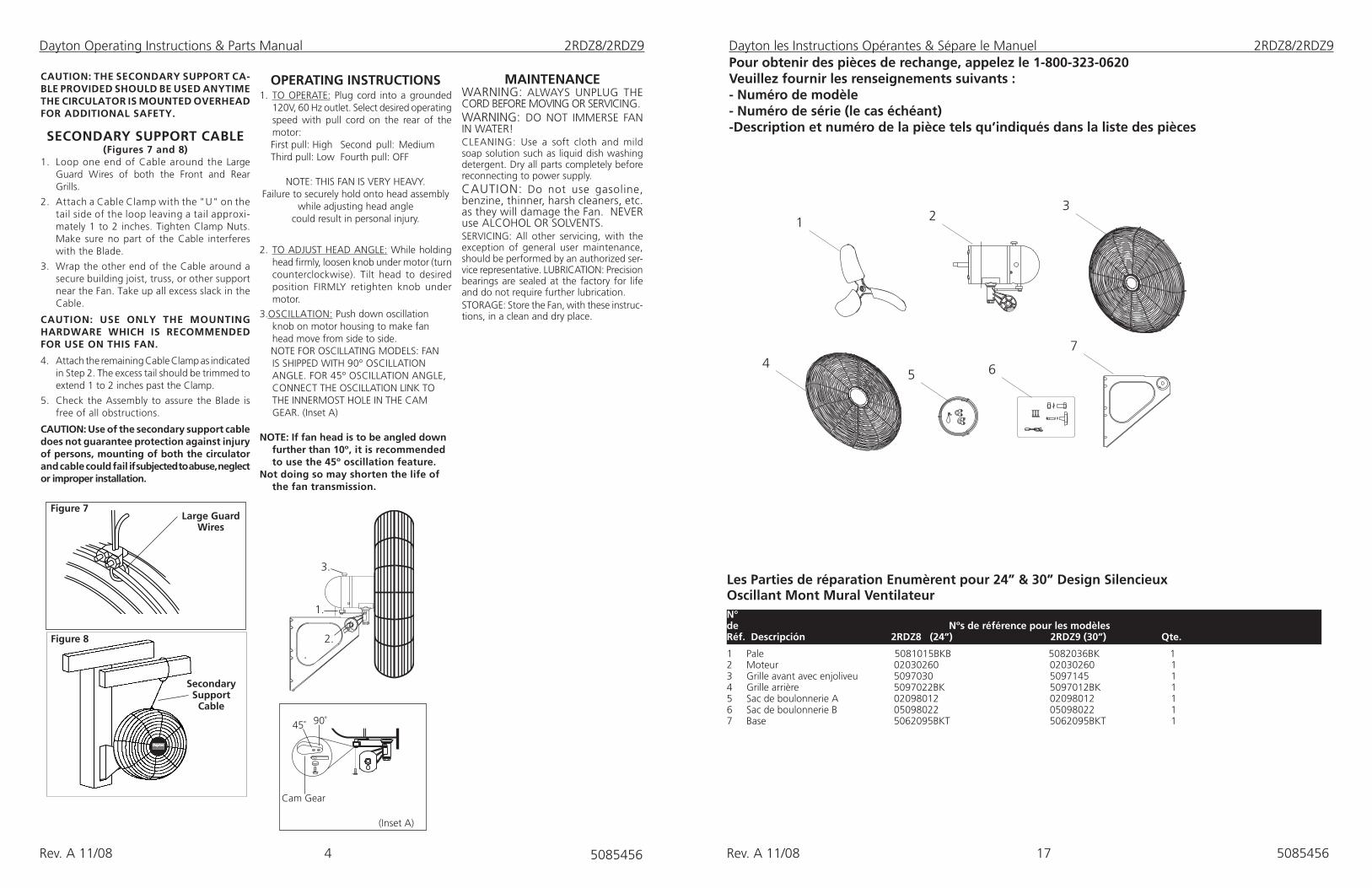
3.OSCILLATION: Push down oscillation knob on motor housing to make fan head move from side to side.
NOTE FOR OSCILLATING MODELS: FAN IS SHIPPED WITH 90º OSCILLATION ANGLE. FOR 45º OSCILLATION ANGLE, CONNECT THE OSCILLATION LINK TO THE INNERMOST HOLE IN THE CAM GEAR. (Inset A)
NOtE: If fan head is to be angled down further than 10º, it is recommended to use the 45º oscillation feature.
Not doing so may shorten the life of the fan transmission.
CAUtION: tHE SECONDARY SUPPORt CA-BLE PROVIDED SHOULD BE USED ANYtIME tHE CIRCULAtOR IS MOUNtED OVERHEAD FOR ADDItIONAL SAFEtY.
SECONDARY SUPPORt CABLE (Figures 7 and 8)
1. Loop one end of Cable around the Large Guard Wires of both the Front and Rear Grills.
2. Attach a Cable Clamp with the "U" on the tail side of the loop leaving a tail approxi-mately 1 to 2 inches. Tighten Clamp Nuts. Make sure no part of the Cable interferes with the Blade.
3. Wrap the other end of the Cable around a secure building joist, truss, or other support near the Fan. Take up all excess slack in the Cable.
CAUtION: USE ONLY tHE MOUNtING HARDWARE WHICH IS RECOMMENDED FOR USE ON tHIS FAN.
4. Attach the remaining Cable Clamp as indicated in Step 2. The excess tail should be trimmed to extend 1 to 2 inches past the Clamp.
5. Check the Assembly to assure the Blade is free of all obstructions.
CAUtION: Use of the secondary support cable does not guarantee protection against injury of persons, mounting of both the circulator and cable could fail if subjected to abuse, neglect or improper installation.
Figure 8
Large Guard Wires
Figure 7
Secondary Support
Cable
MAINtENANCEWARNING: ALWAYS UNPLUG THE CORD BEFORE MOVING OR SERVICING.WARNING: DO NOT IMMERSE FAN IN WATER!CLEANING: Use a soft cloth and mild soap solution such as liquid dish washing detergent. Dry all parts completely before reconnecting to power supply. CAUTION: Do not use gasoline, benzine, thinner, harsh cleaners, etc. as they will damage the Fan. NEVER use ALCOHOL OR SOLVENTS.SERVICING: All other servicing, with the exception of general user maintenance, should be performed by an authorized ser-vice representative. LUBRICATION: Precision bearings are sealed at the factory for life and do not require further lubrication.STORAGE: Store the Fan, with these instruc-tions, in a clean and dry place.
1.
2.
3.
(Inset A)
Cam Gear
90˚ 45˚
4
Dayton Operating Instructions & Parts Manual 2RDZ8/2RDZ9
Rev. A 11/08 5085456
Dayton les Instructions Opérantes & Sépare le Manuel 2RDZ8/2RDZ9
Les Parties de réparation Enumèrent pour 24” & 30” Design Silencieux Oscillant Mont Mural Ventilateur
1 Pale 5081015BKB 5082036BK 1 2 Moteur 02030260 02030260 1 3 Grille avant avec enjoliveu 5097030 5097145 14 Grille arrière 5097022BK 5097012BK 15 Sac de boulonnerie A 02098012 02098012 16 Sac de boulonnerie B 05098022 05098022 17 Base 5062095BKT 5062095BKT 1
2N° de Nºs de référence pour les modèles Réf. Descripción 2RDZ8 (24”) 2RDZ9 (30”) Qte.
Pour obtenir des pièces de rechange, appelez le 1-800-323-0620Veuillez fournir les renseignements suivants :- Numéro de modèle- Numéro de série (le cas échéant)-Description et numéro de la pièce tels qu’indiqués dans la liste des pièces
13
2
5 6
74
17Rev. A 11/08 5085456
5
Dayton Operating Instructions & Parts Manual 2RDZ8/2RDZ9
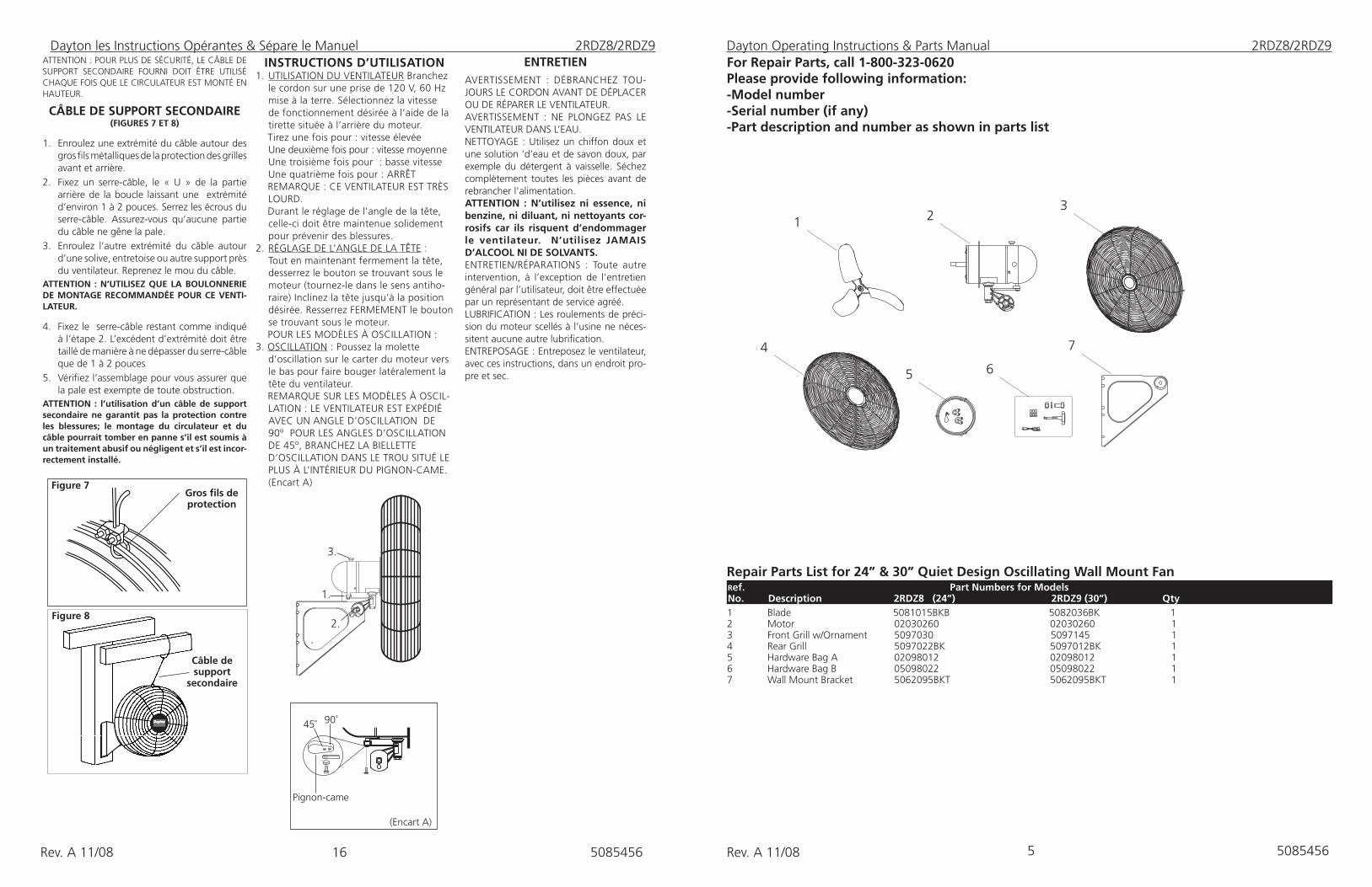
Repair Parts List for 24” & 30” Quiet Design Oscillating Wall Mount Fan 1 Blade 5081015BKB 5082036BK 1 2 Motor 02030260 02030260 1 3 Front Grill w/Ornament 5097030 5097145 14 Rear Grill 5097022BK 5097012BK 15 Hardware Bag A 02098012 02098012 16 Hardware Bag B 05098022 05098022 17 Wall Mount Bracket 5062095BKT 5062095BKT 1
2 Ref. Part Numbers for Models No. Description 2RDZ8 (24”) 2RDZ9 (30”) Qty
For Repair Parts, call 1-800-323-0620Please provide following information:-Model number-Serial number (if any)-Part description and number as shown in parts list
5085456
13
2
4
5 6
7
INStRUCtIONS D’UtILISAtION1. UTILISATION DU VENTILATEUR Branchez
le cordon sur une prise de 120 V, 60 Hz mise à la terre. Sélectionnez la vitesse de fonctionnement désirée à l’aide de la tirette située à l’arrière du moteur.
Tirez une fois pour : vitesse élevée Une deuxième fois pour : vitesse moyenne Une troisième fois pour : basse vitesse Une quatrième fois pour : ARRÊT
REMARQUE : CE VENTILATEUR EST TRÈS LOURD.
Durant le réglage de l’angle de la tête, celle-ci doit être maintenue solidement pour prévenir des blessures.
2. RÉGLAGE DE L’ANGLE DE LA TÊTE : Tout en maintenant fermement la tête, desserrez le bouton se trouvant sous le moteur (tournez-le dans le sens antiho-raire) Inclinez la tête jusqu’à la position désirée. Resserrez FERMEMENT le bouton se trouvant sous le moteur.
POUR LES MODÈLES À OSCILLATION :3. OSCILLATION : Poussez la molette
d’oscillation sur le carter du moteur vers le bas pour faire bouger latéralement la tête du ventilateur.
REMARQUE SUR LES MODÈLES À OSCIL-LATION : LE VENTILATEUR EST EXPÉDIÉ AVEC UN ANGLE D’OSCILLATION DE 90º POUR LES ANGLES D’OSCILLATION DE 45º, BRANCHEZ LA BIELLETTE D’OSCILLATION DANS LE TROU SITUÉ LE PLUS À L’INTÉRIEUR DU PIGNON-CAME. (Encart A)
ATTENTION : POUR PLUS DE SÉCURITÉ, LE CÂBLE DE SUPPORT SECONDAIRE FOURNI DOIT ÊTRE UTILISÉ CHAQUE FOIS QUE LE CIRCULATEUR EST MONTÉ EN HAUTEUR.
CÂBLE DE SUPPORt SECONDAIRE (FIGURES 7 Et 8)
1. Enroulez une extrémité du câble autour des gros fils métalliques de la protection des grilles avant et arrière.
2. Fixez un serre-câble, le « U » de la partie arrière de la boucle laissant une extrémité d’environ 1 à 2 pouces. Serrez les écrous du serre-câble. Assurez-vous qu’aucune partie du câble ne gêne la pale.
3. Enroulez l’autre extrémité du câble autour d’une solive, entretoise ou autre support près du ventilateur. Reprenez le mou du câble.
AttENtION : N’UtILISEZ QUE LA BOULONNERIE DE MONtAGE RECOMMANDÉE POUR CE VENtI-LAtEUR.
4. Fixez le serre-câble restant comme indiqué à l’étape 2. L’excédent d’extrémité doit être taillé de manière à ne dépasser du serre-câble que de 1 à 2 pouces
5. Vérifiez l’assemblage pour vous assurer que la pale est exempte de toute obstruction.
AttENtION : l’utilisation d’un câble de support secondaire ne garantit pas la protection contre les blessures; le montage du circulateur et du câble pourrait tomber en panne s’il est soumis à un traitement abusif ou négligent et s’il est incor-rectement installé.
Figure 8
Gros fils de protection
Figure 7
Câble de support
secondaire
ENtREtIENAVERTISSEMENT : DÉBRANCHEZ TOU-JOURS LE CORDON AVANT DE DÉPLACER OU DE RÉPARER LE VENTILATEUR.AVERTISSEMENT : NE PLONGEZ PAS LE VENTILATEUR DANS L’EAU.NETTOYAGE : Utilisez un chiffon doux et une solution ‘d’eau et de savon doux, par exemple du détergent à vaisselle. Séchez complètement toutes les pièces avant de rebrancher l’alimentation. AttENtION : N’utilisez ni essence, ni benzine, ni diluant, ni nettoyants cor-rosifs car ils risquent d’endommager le ventilateur. N’utilisez JAMAIS D’ALCOOL NI DE SOLVANtS.ENTRETIEN/RÉPARATIONS : Toute autre intervention, à l’exception de l’entretien général par l’utilisateur, doit être effectuée par un représentant de service agréé. LUBRIFICATION : Les roulements de préci-sion du moteur scellés à l’usine ne néces-sitent aucune autre lubrification.ENTREPOSAGE : Entreposez le ventilateur, avec ces instructions, dans un endroit pro-pre et sec.
1.
2.
3.
(Encart A)
Pignon-came
90˚ 45˚
Dayton les Instructions Opérantes & Sépare le Manuel 2RDZ8/2RDZ9
16Rev. A 11/08 5085456 Rev. A 11/08
15Rev. A 11/086Rev. A 11/08 5085456 5085456
LIMITED WARRANTY
DAYTON ONE-YEAR LIMITED WARRANTY. DAYTON® 2RDZ8 and 2RDZ9, MODELS COVERED IN THIS MANUAL, ARE WARRANTED BY DAYTON ELECTRIC MFG. CO. (DAYTON) TO THE ORIGINAL USER AGAINST DEFECTS IN WORK-MANSHIP OR MATERIALS UNDER NORMAL USE FOR ONE YEAR AFTER DATE OF PURCHASE. ANY PART WHICH IS DETERMINED TO BE DEFECTIVE IN MATERIAL OR WORKMANSHIP AND RETURNED TO AN AUTHORIZED SERVICE LOCATION, AS DAYTON DESIGNATES, SHIPPING COSTS PREPAID, WILL BE, AS THE EXCLUSIVE REMEDY, REPAIRED OR REPLACED AT DAYTON’S OPTION. FOR LIMITED WARRANTY CLAIM PROCEDURES, SEE “PROMPT DISPOSITION” BELOW. THIS LIMITED WARRANTY GIVES PURCHASERS SPECIFIC LEGAL RIGHTS WHICH VARY FROM JURISDICTION TO JURISDICTION.
LIMITATION OF LIABILITY.TO THE EXTENT ALLOWABLE UNDER APPLICABLE LAW, DAYTON’S LIABILITY FOR CONSE-QUENTIAL AND INCIDENTIAL DAMAGES IS EXPRESSLY DISCLAIMED. DAYTON’S LIABILITY IN ALL EVENTS IS LIMITED TO AND SHALL NOT EXCEED THE PURCHASE PRICE PAID.
WARRANTY DISCLAIMER. A DILIGENT EFFORT HAS BEEN MADE TO PROVIDE PRODUCT INFORMATION AND ILLUS-TRATE THE PRODUCTS IN THIS LITERATURE ACCURATELY; HOWEVER, SUCH INFORMATION AND ILLUSTRATIONS ARE FOR THE SOLE PURPOSE OF IDENTIFICATION, AND DO NOT EXPRESS OR IMPLY A WARRANTY THAT THE PRODUCTS ARE MERCHANTABLE, OR FIT FOR A PARTICULAR PURPOSE, OR THAT THE PRODUCTS WILL NECESSARILY CONFORM TO THE ILLUSTRATIONS OR DESCRIPTIONS. EXCEPT AS PROVIDED BELOW, NO WARRANTY OR AFFIRMATION OF FACT, EXPRESSED OR IMPLIED, OTHER THAN AS STATED IN THE “LIMITED WARRANTY” ABOVE IS MADE OR AUTHORIZED BY DAYTON.
Technical Advice and Recommendations, Disclaimer. Notwithstanding any past practice or dealings or trade custom, sales shall not include the furnishing or technical advice or assistance or system design. Dayton assumes no obligations or liability on account of any unauthorized recommendations, opinions or advice as to the choice, installa-tion or use of products.
Product Suitability. Many jurisdictions have codes and regulations governing sales, construction, installation, and/or use of products for certain purposes, which may vary from those in neighboring areas. While attempts are made to as-sure that Dayton products comply with such codes, Dayton cannot guarantee compliance, and cannot be responsible for how the product is installed or used. Before purchase and use of a product, review the product applications, and all applicable national and local codes and regulations, and be sure that the product, installation, and use will comply with them.
Certain aspects of disclaimers are not applicable to consumer products; e.g.,(a) some jurisdictions do not allow the ex-clusion or limitation of incidental or consequential damages, so the above limitation or exclusion may not apply to you; (b) also, some jurisdictions do not allow a limitation on how long an implied warranty lasts, consequently the above limitation may not apply to you; and (c) by law, during the period of this Limited Warranty, any implied warranties of implied merchantability or fitness for a particular purpose applicable to consumer products purchased by consumers, may not be excluded or otherwise disclaimed.
Prompt Disposition. A good faith effort will be made for prompt correction or other adjustment with respect to any product which proves to be defective within limited warranty. For any product believed to be defective within limited warranty, first write or call dealer from whom the product was purchased. Dealer will give additional directions. If unable to resolve satisfactorily, write to Dayton at address below, giving dealer’s name, address, date, and number of dealer’s invoice, and describing the nature of the defect. Title and risk of loss pass to buyer on delivery to common car-rier. If product was damaged in transit to you, file claim with carrier.
Manufactured for Dayton Electric Mfg. Co., 5959 W. Howard St., Niles, Illinois 60714-4014 U.S.A
2Operating Instructions & Parts Manual 2RDZ8/2RDZ9
Manufactured for Dayton Electric Mfg. Niles, Illinois 60714 U.S.A
ENG L I S H
Dayton® 24” & 30”Quiet Design Oscillating Wall Mount Fan
ASSEMBLAGE DE LA GRILLE Et DES PALES (FIgURES 3 ET 4)1. Installez la grille arrière sur le moteur, en
alignant les six trous de la grille sur les six trous filetés du moteur. Passez (6) vis hexagonales de 10-32 X 5/16 po dans la grille arrière pour les insérer dans le moteur. Serrez solidement les (6) vis. (Figure 3)
2. Poussez la pale du ventilateur sur l’arbre du moteur en centrant le moyeu dans la direction opposée au moteur, jusqu’à ce qu’elle bute contre l’arbre (encart A) Alignez le boulon à tête carrée sur le méplat de l’arbre du moteur. SERREZ TRÈS SOLIDE-MENT À L’AIDE D’UNE CLÉ À MOLETTE. Le serrage insuffisant du boulon pourrait provoquer des dommages matériels ou des blessures,
3. Maintenez la grille avant de manière que le nom, au centre, soit à l’endroit et visible horizontalement. À partir du haut : fixez la grille avant sur la grille arrière en glissant les fils munis de crochets de la grille avant par-dessus l’anneau extérieur de la grille ar-rière. (Figure 4 / Détail A). Pour terminer l’assemblage des crochets le plus au fond, un tournevis à lame plate sera nécessaire. Tenez-vous derrière le ventilateur. Glissez la lame plate du tournevis entre les grilles avant et arrière, près de l’un des crochets non fixés. (Figure 4 / DéTAIL B) TIREZ LA POIGNÉE DU TOURNEVIS VERS LE HAUT, EN DIRECTION DE LA GRILLE ARRIÈRE. GLISSEZ EN LE POUSSANT LE CROCHET DE LA GRILLE AVANT PAR-DESSUS L’ANNEAU EXTÉRIEUR DE LA GRILLE ARRIÈRE. RÉPÉTEZ CETTE PROCÉDURE POUR LES AUTRES CROCHETS.
AttENtION : NE COURBEZ PAS LES FILS DES GRILLES AVANt OU ARRIÈRE.
INStALLAtION DU SUPPORt MURALREMARQUE : installez toujours le support sur des montants de 2 x 4 po au minimum.
1. Insérez le boulon de 7/16-14 x 3 1/2 po dans le support mural, puis dans le contre-écrou de 7/16-14. Serrez au moyen de clés à molette.
2. LA BOULONNERIE SERVANT À FIXER LE SUP-PORT MURAL SUR LE MONTANT N’EST PAS FOURNIE. Localiser le montant le plus proche de l’emplacement souhaité du ventilateur. Fixez le support mural sur le montant au moyen de (3) vis tire-fond de 5/16 po de diamètre x 2 po de long.
3. Positionnez le col du moteur et alignez le trou du pivot sur le plus grand trou du support mural. (Figure 1)
4. Insérez le boulon hexagonal de 1/2 x 1 po (tête de 3/4 po) dans le col du moteur et dans le support mural. Placez une rondelle de blocage fendue de 1/2 po de diamètre, puis l’écrou de 1/2 po de diamètre (tête de 3/4 po) et serrez à fond au moyen d’une clé à molette de 1 po.
5. Depuis le même côté du col du moteur, insérez un boulon de carrosserie 1/4-20 X 1 5/8 po dans la fente en arc du col du moteur et dans le trou du support mural.
Pour fixer : Placez une rondelle plate de 1/4 po, une rondelle de blocage de 1/4 po à dentelure interne, une deuxième rondelle plate de 1/4 po puis serrez la molette sur le reste du filetage. L’assemblage final du moteur sur le support de la plaque de montage murale est illustré Figure 2
Figure 2
Assemblage final du
moteur surle support
mural
Montage mural
Figure 3
Encart A
Détail BBottom Hooks
Détail ACrochets
supérieurs
Figure 4
Figure 1
Wall Bracket
7/16-14 X 3 1/2" Boulon
Contre-écrou de 7/16-14
Serre-câble
Serre-câble
Cheminement du câble
Dayton les Instructions Opérantes & Sépare le Manuel 2RDZ8/2RDZ9
FRAN ÇI S
14Rev. A 11/08 7Rev. A 11/08 5085456
Dayton les Instructions Opérantes & Sépare le Manuel 2RDZ8/2RDZ9
GÉNÉRALItÉS SUR LA SÉCURItÉLors de l’utilisation d’appareils électriques, les précau-tions élémentaires suivantes doivent toujours être prises afin de réduire les risques d’incendie, de choc électrique et de blessures corporelles :
1. Lire toutes les instructions avant d’utiliser le ventilateur. 2. Veiller à ce que la source d’alimentation soit conforme à celle spécifiée pour le ventilateur. 3. N’utiliser ce ventilateur que de la manière décrite dans le présent manuel. Toute autre utilisation non recommandée par le fabricant peut provoquer un incendie un choc électrique ou des blessures corporelles.4. Pour réduire le risque de blessure et de
choc électrique, éviter toute manipulation inutile du ventilateur et ne pas le placer dans des endroits où des enfants peuvent l'atteindre.
5. Débrancher le cordon d’alimentation avant tout entretien ou déplacement du ventilateur.
AVERtISSEMENt : NE PAS COMPtER UNIQUE-MENt SUR LE BOUtON MARCHE-ARRÊt POUR COUPER LE COURANt PENDANt L'INStALLAtION, LA RÉPARAtION OU L'ENtREtIEN DU VENtILAtEUR. tOUJOURS DÉBRANCHER LE CORDON D’ALIMENtAtION.6. Ce ventilateur NE doit PAS être utilisé dans
des environnements potentiellement dan-gereux, en milieu inflammable, explosif, humide ou chargé de produits chimiques.
7. NE PAS installer le ventilateur sur une fenêtre ou à sa proximité. La pluie peut créer un risque électrique.
8. Réassembler complètement de ventilateur conformément aux instructions avant de rebrancher l’alimentation.
9. Le cordon d’alimentation est muni d’une fiche à trois broches mise à la terre qui doit être insérée dans une prise compatible (à 3 trous). La broche de mise à la terre ne doit en aucun cas être coupée de la fiche. Si une prise murale ne dispose que de deux trous,
elle doit être remplacée par une prise à trois trous correctement mise à la terre et installée con-formément aux prescriptions du National Electric al Code (NEC) et de tous les codes et ordonnance locaux en vigueur. Ce travail ne doit être effectué que par un électricien qualifié, au moyen de fils de cuivre uniquement.
AVERtISSEMENt : L’UtILISAtION D’UN ADAPtAtEUR DE FICHE À tROIS BROCHES SUR UNE FICHE À DEUX BROCHES N’ESt PAS RECOM-MANDÉ. UNE MAUVAISE CON-NEXION PEUt CRÉER UN RISQUE DE CHOC ÉLECtRIQUE. CE tYPE D’ADAPtAtEUR ESt INtERDIt AU CANADA.10. Dans la mesure du possible,
éviter d’utiliser des cordons pro-longateurs. S’il est nécessaire d’en utiliser un, minimiser le risque de surchauffe en vérifiant qu’il est homologué UL. Ne jamais se servir d’un seul cordon prolongateur pour faire fonctionner plusieurs ventilateurs. Ne brancher le ven-tilateur sur aucun autre appareil relié par le cordon tel qu’une barre multiprise, un enrouleur de câble, un limiteur de surtension, des adaptateurs multiprises ou des assainisseurs d’air branchés sur prise. L’utilisation de tels appareils peut créer un risque d’incendie.
11. Ne pas faire fonctionner un venti-lateur si son cordon ou sa fiche a été endommagé(e), s’il fonctionne mal, s’il est tombé ou a été abîmé de quelque manière que ce soit. Le retourner à un centre de ser-vice agréé où il sera soumis à une vérification ainsi qu’à des réglages ou réparations électriques ou mé-caniques.
12. Ne pas insérer ni laisser les doigts ou des corps étrangers pénétrer dans les orifices de ventilation ou d’échappement car cela peut provoquer un choc électrique, un incendie ou endommager le ven-
tilateur. Ne pas bloquer ni modifier le ventilateur de quelque manière que ce soit pendant le fonctionnement.
13. Situer le cordon d’alimentation de manière que le ventilateur ou d’autres objets ne reposent pas dessus. Ne pas faire passer le cordon d’alimentation sous de la moquette ou des tapis de sol. Ne pas recouvrir le cordon d’alimentation avec des tapis de corridor ou des articles similaires. Ne pas faire passer le cordon d’alimentation par des entrées de porte, des fenêtres ou des endroits où il pourrait gêner. Le disposer à l’écart des voies de passage. Le placer dans des endroits où il ne pourra faire trébucher personne.
14. Ce ventilateur n’est pas prévu pour être utilisé dans des endroits mouillés ou humides. Ne jamais le placer dans des endroits d’où il risque de tomber dans l’eau.
15. Ne pas utiliser le ventilateur à l’extérieur.
16. Ce ventilateur ne convient pas pour un usage dans des endroits dangereux. Consulter soit l’article 500 du National Electric Code (NEC) soit les codes ou normes provinciales ou locales en vigueur s’appliquant à l’alimentation électrique dans les endroits dangereux. CE VENTILATEUR NE SATISFAIT PAS AUX EXIGENCES DE L’ARTICLE 500 (2008) DU NEC.
AVERtISSEMENt : POUR RÉDUIRE LE RISQUE D’INCENDIE OU DE CHOC ÉLEC-tRIQUE, NE PAS UtILISER CE VENtILAtEUR AVEC DES DISPOSItIFS DE CONtRÔLE DE VItESSE tRANSIStORISÉS AttENtION : EN RAISON DE LA tAILLE Et DU POIDS DE CE VENtILAtEUR, VEILLER À CE QUE tOUtES LES PIÈCES SOIENt ASSEMBLÉES CONFOR-MÉMENt AUX INStRUCtIONS, FAUtE DE QUOI LE VENtILAtEUR POURRAIt SE SÉPARER PENDANt LE FONCtIONNEMENt Et CAUSER DES BLESSURES.
Dayton® 24” & 30” Design Silencieux Oscillant Mont Mural Ventilateur
A
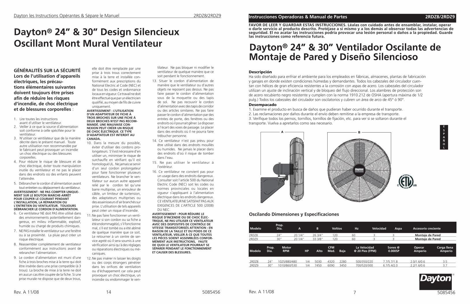
DescripciónHa sido diseñado para enfriar el ambiente para los empleados en fábricas, almacenes, plantas de fabricación y garajes en donde existen condiciones húmedas y demandantes. Todos los cabezales del circulador cuen-tan con hélices de gran eficiencia resistentes a la corrosión con aspas de acero. Los cabezales del circulador utilizan un ajuste de inclinación vertical y de bloqueo del flujo direccional. Los alambres de protección son de acero recubierto negro resistente y cumplen con la norma 1910.212 de OSHA (apertura máxima de 1/2 pulg.) Todos los cabezales del circulador son oscilatorios y cubren un área de arco de 45° ó 90°.
Las Instrucciones operadoras & Manual de Partes 2Instrucciones Operadoras & Manual de Partes 2RDZ8/2RDZ9
Dayton® 24” & 30” Ventilador Oscilante de Montaje de Pared y Diseño Silencioso
ESP A Ñ O L
2RDZ8 24” 1025/880/480 1/4 5030 4320 2280 500/350/220 7.7/5.7/1.8 2.0/1.6/0.6 3.5 2RDZ9 30” 1010/860/530 1/4 7450 6090 3450 700/520/300 6.7/5.4/2.0 2.2/1.6/0.6 3.7
Prop. Motor CFM La Velocidad Sones @ Operar Carga llena Modelo Dia. RPM HP Alto Med. Baja @ 20 Pies (FPM) 0.000SP Amperio Amperio
FAVOR DE LEER Y GUARDAR EStAS INStRUCCIONES. Léalas con cuidado antes de ensamblar, instalar, operar o darle servicio al producto descrito. Protéjase a sí mismo y a los demás al observar todas las advertencias de seguridad. El no acatar las instrucciones podría provocar una lesión personal o daños a la propiedad. Guarde las instrucciones como referencia futura.
Desempacado1. Examine el producto en busca de daños que pudieran haber ocurrido durante el transporte.2. Las reclamaciones por daños durante el envío deben remitirse a la empresa de transporte.3. Verifique todos los pernos, tornillos, tornillos de fijación, etc. para ver si se soltaron durante el transporte. Vuelva a apretarlos como sea necesario.
2 Prop. Modelo Dia. A B Voltios Hz Velocidad Aspa Accesorio creciente
Oscilando Dimensiones y Especificaciones
2RDZ8 24” 20 1/4” 26 3/4” 120 60 3 3 Montaje de Pared 2RDZ9 30” 20 1/4” 33 3/8” 120 60 3 3 Montaje de Pared
5085456
13Rev. A 11/088Rev. A 11/08 5085456
Dayton® 24” & 30” Ventilador Oscilante de Montaje de Pared y Diseño Silencioso
Dayton Instrucciones Operadoras & Manual de Partes 2RDZ8/2RDZ9
INFORMACIÓN GENERALSOBRE SEGURIDADAl utilizar aparatos eléctricos, siempre deben observarse ciertas precauciones básicas para dis-minuir el riesgo de incendio, descargas eléctricas y lesiones personales, que incluyen lo siguiente:
1. Antes de usar el ventilador, lea todas las instrucciones. 2. Cerciórese de que la corriente eléctrica cumpla con las especificaciones eléctricas del ventilador.3. Utilice este ventilador sólo de la manera que se indica en este manual. Cualquier otro uso no recomendado por el fabricante puede ocasionar un incendio, descarga eléctrica o lesiones personales.4. Para reducir el riesgo de que ocurran lesiones personales y una descarga eléctrica, no debe permitirse que los niños jueguen con él ni debe colocarse en un lugar donde puedan alcanzarlo los niños pequeños.5. Desconecte el cable eléctrico antes de darle servicio o mover el ventilador.ADVERtENCIA: AL INStALAR O DAR SERVICIO AL VENtILADOR, NO DEPENDA SÓLO DEL INtERRUPtOR DE ENCENDIDO Y APAGADO PARA DESCONECtAR LA ELEC-tRICIDAD. DESCONECtE SIEMPRE EL CABLE ELÉCtRICO DEL tOMACORRIENtE.6. NO debe utilizar este ventilador en lugares potencialmente peligrosos, por ejemplo,en lugares con productos inflamables, explosi vos, saturados de sustancias químicas o una atmósfera húmeda.7. NO utilice el ventilador en una ventana o cerca de ella. La lluvia puede provocar un riesgo eléctrico.8. Antes de volver a conectarlo a la corriente eléctrica, vuelva a ensamblar completamente el ventilador según las instrucciones.9. El cable de corriente viene equipado con una clavija de tres espigas con conexión a tierra que debe enchufarse en un receptáculo adec uado. Bajo ninguna circunstancia debe cortarse la espiga de conexión a tierra del enchufe. En aquellos lugares en los que exista un receptáculo de pared para dos espigas, debe ser reemplazado con un receptáculo de tres espigas correctamente conectado a tierra, instalado de acuerdo con el Código Eléctrico Nacional (NEC) y todos los códigos y regla mentos locales pertinentes. El trabajo sólo
debe realizarlo un electricista calificado utilizando alambres de cobre únicamente.ADVERtENCIA: NO SE RECOMIENDA UtI-LIZAR UN ADAPtADOR DE tRES A DOS ESPIGAS. UNA CONEXIÓN INCORRECtA PODRÍA GENERAR EL RIESGO DE DES-CARGA ELÉCtRICA. EN CANADÁ NO SE PERMItE EL USO DE tALES ADAPtADORES.10. En donde sea posible, evite utilizar cables de extensión. Si necesita usarlos disminuya al mínimo el riesgo de sobre calentamiento cerciorándose que tengan la aprobación de UL. Nunca utilice un solo cable de extensión para hacer uncionar más de ventilador. No enchufe el ventilador en ningún dispositivo conectado con un cable eléctrico, por ejemplo, un contacto múltiple, un cordón de carrete, un regulador de voltaje, adaptadores múltiples para tomacorrientes o aromatizantes del am biente con tomacorrientes incorporados. El uso de este tipo de dispositivos puede crear un riesgo de incendio.11. No haga funcionar un ventilador con una clavija o cable eléctrico dañados o después del mal funcionamiento del ventilador, si se ha caído o dañado de alguna manera. Devuelva el ventilador a una concesionaria de servicio autoriza do para que lo revisen y realicen los ajustes o reparaciones eléctricas o mecánicas.12. No inserte ni permita que los dedos o los objetos externos entren en las aberturas de ventilación o descarga ya que pueden provocar una descarga eléctrica, un incendio o daños al venti lador. No bloquee ni altere el ventilador de ninguna manera mientras está funcio nando. 13. Ubique el cable eléctrico de tal man era que el ventilador u otros objetos no se apoyen sobre él. No pase el cable eléctrico por debajo de alfombras o ta petes. No cubra el cable eléctrico con al fombras longitudinales ni artículos similares. No pase el cable eléctrico a través de las puertas, ventanas o áreas en donde pueda aplastarse. Coloque el cable eléctrico alejado del tráfico en las salas y en los lugares en donde puede provocar tropiezos.
14. Este ventilador no ha sido diseñado para ser utilizado en lugares moja dos o húmedos. Nunca coloque un ventilador en lugares en que podría caerse al agua.15. No debe usar el ventilador a la intemperie.16. Este ventilador no es apto para usar en lugares peligrosos. Consulte el Artículo 500 del Código Eléctrico Nacional (NEC) o los códigos es tatales o locales o las normas perti nentes a las especificaciones eléctricas en lugares peligrosos. ESTE VENTILADOR NO CUMPLE CON LOS REQUISITOS DEL ARTÍCU- LO 500 DEL NEC (2008).ADVERtENCIA: DISMINUYA EL RIESGO DE INCENDIO O DESCARGA ELÉCtRICA — NO UtILICE EStE VEN-tILADOR CON UN DISPOSItIVO DE EStADO SÓLIDO PARA EL CONtROL DE LA VELOCIDAD. PRECAUCIÓN: DEBIDO AL tAMAÑO Y PESO DE EStE VENtILADOR, CERCIÓRESE DE QUE tODAS LAS PIEZAS EStÉN COMPLEtAMENtE ENSAMBLADAS DE ACUERDO A LAS INStRUC-CIONES. EL NO HACERLO PUEDE PROVOCAR QUE SE DESARME EL VENtILADOR DURANtE EL FUN-CIONAMIENtO Y QUE PROVOQUE LESIONES PERSONALES.
A
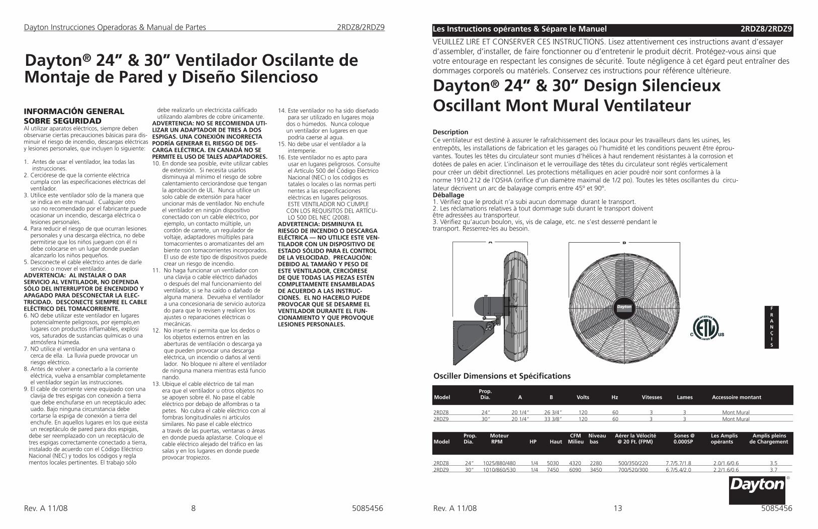
DescriptionCe ventilateur est destiné à assurer le rafraîchissement des locaux pour les travailleurs dans les usines, les entrepôts, les installations de fabrication et les garages où l’humidité et les conditions peuvent être éprou-vantes. Toutes les têtes du circulateur sont munies d’hélices à haut rendement résistantes à la corrosion et dotées de pales en acier. L’inclinaison et le verrouillage des têtes du circulateur sont réglés verticalement pour créer un débit directionnel. Les protections métalliques en acier poudré noir sont conformes à la norme 1910.212 de l’OSHA (orifice d’un diamètre maximal de 1/2 po). Toutes les têtes oscillantes du circu-lateur décrivent un arc de balayage compris entre 45º et 90º.
2Les Instructions opérantes & Sépare le Manuel 2RDZ8/2RDZ9
Dayton® 24” & 30” Design Silencieux Oscillant Mont Mural Ventilateur
Déballage1. Vérifiez que le produit n’a subi aucun dommage durant le transport.2. Les réclamations relatives à tout dommage subi durant le transport doivent être adressées au transporteur.3. Vérifiez qu’aucun boulon, vis, vis de calage, etc. ne s’est desserré pendant le transport. Resserrez-les au besoin.
FRAN ÇI S
Osciller Dimensions et Spécifications
2RDZ8 24” 20 1/4” 26 3/4” 120 60 3 3 Mont Mural 2RDZ9 30” 20 1/4” 33 3/8” 120 60 3 3 Mont Mural
2 Prop. Model Dia. A B Volts Hz Vitesses Lames Accessoire montant
2RDZ8 24” 1025/880/480 1/4 5030 4320 2280 500/350/220 7.7/5.7/1.8 2.0/1.6/0.6 3.5 2RDZ9 30” 1010/860/530 1/4 7450 6090 3450 700/520/300 6.7/5.4/2.0 2.2/1.6/0.6 3.7
Prop. Moteur CFM Niveau Aérer la Vélocité Sones @ Les Amplis Amplis pleins Model Dia. RPM HP Haut Milieu bas @ 20 Ft. (FPM) 0.000SP opérants de Chargement
VEUILLEZ LIRE ET CONSERVER CES INSTRUCTIONS. Lisez attentivement ces instructions avant d’essayer d’assembler, d’installer, de faire fonctionner ou d’entretenir le produit décrit. Protégez-vous ainsi que votre entourage en respectant les consignes de sécurité. Toute négligence à cet égard peut entraîner des dommages corporels ou matériels. Conservez ces instructions pour référence ultérieure.
5085456
Rev. A 11/08 508545612 9Rev. A 11/08 5085456
ENSAMBLADO DE PARRILLAS Y ASPAS
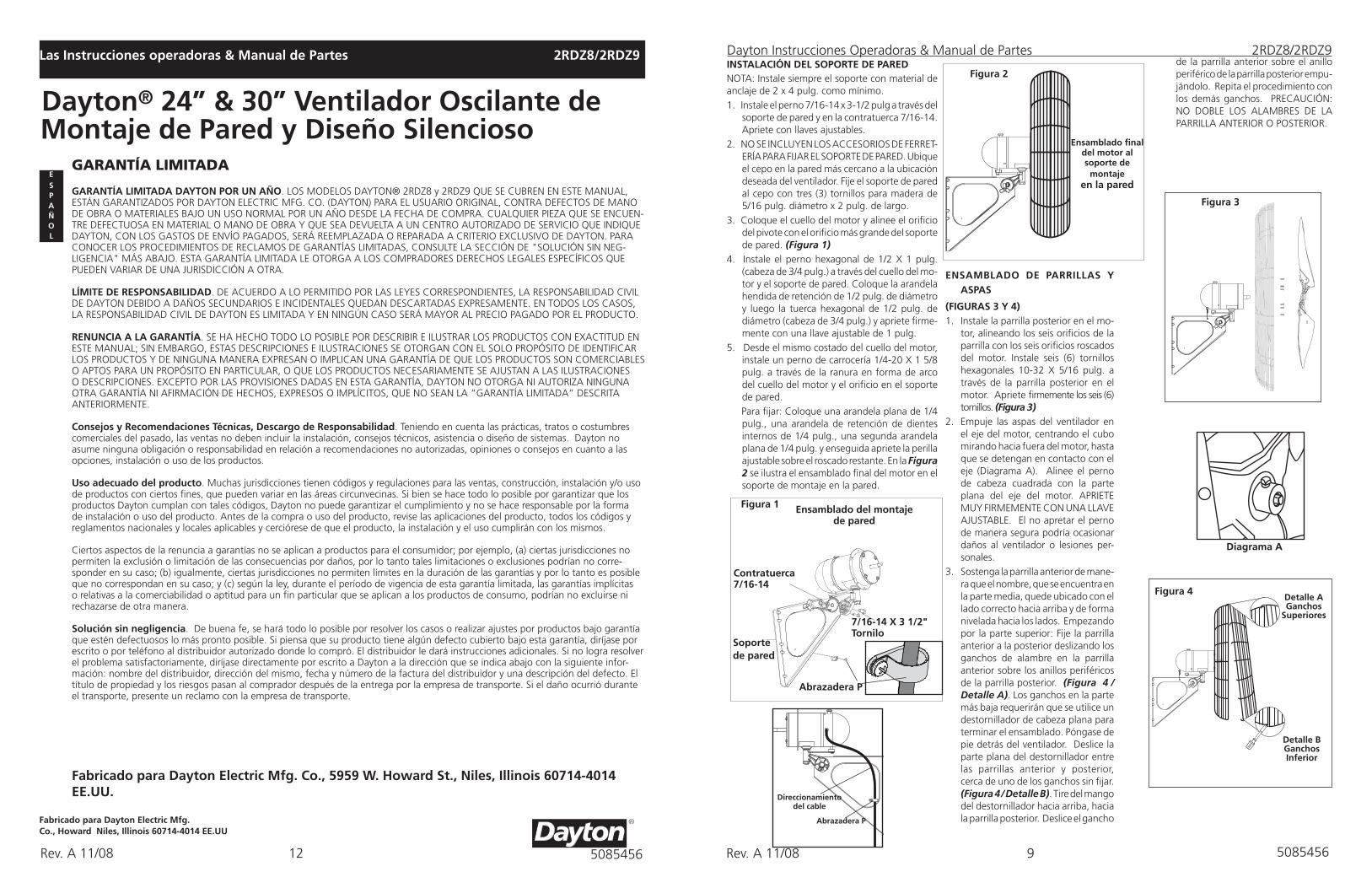
(FIGURAS 3 Y 4)1. Instale la parrilla posterior en el mo-
tor, alineando los seis orificios de la parrilla con los seis orificios roscados del motor. Instale seis (6) tornillos hexagonales 10-32 X 5/16 pulg. a través de la parrilla posterior en el motor. Apriete firmemente los seis (6) tornillos. (Figura 3)
2. Empuje las aspas del ventilador en el eje del motor, centrando el cubo mirando hacia fuera del motor, hasta que se detengan en contacto con el eje (Diagrama A). Alinee el perno de cabeza cuadrada con la parte plana del eje del motor. APRIETE MUY FIRMEMENTE CON UNA LLAVE AJUSTABLE. El no apretar el perno de manera segura podría ocasionar daños al ventilador o lesiones per-sonales.
3. Sostenga la parrilla anterior de mane-ra que el nombre, que se encuentra en la parte media, quede ubicado con el lado correcto hacia arriba y de forma nivelada hacia los lados. Empezando por la parte superior: Fije la parrilla anterior a la posterior deslizando los ganchos de alambre en la parrilla anterior sobre los anillos periféricos de la parrilla posterior. (Figura 4 / Detalle A). Los ganchos en la parte más baja requerirán que se utilice un destornillador de cabeza plana para terminar el ensamblado. Póngase de pie detrás del ventilador. Deslice la parte plana del destornillador entre las parrillas anterior y posterior, cerca de uno de los ganchos sin fijar. (Figura 4 / Detalle B). Tire del mango del destornillador hacia arriba, hacia la parrilla posterior. Deslice el gancho
INStALACIÓN DEL SOPORtE DE PAREDNOTA: Instale siempre el soporte con material de anclaje de 2 x 4 pulg. como mínimo.1. Instale el perno 7/16-14 x 3-1/2 pulg a través del
soporte de pared y en la contratuerca 7/16-14. Apriete con llaves ajustables.
2. NO SE INCLUYEN LOS ACCESORIOS DE FERRET-ERÍA PARA FIJAR EL SOPORTE DE PARED. Ubique el cepo en la pared más cercano a la ubicación deseada del ventilador. Fije el soporte de pared al cepo con tres (3) tornillos para madera de 5/16 pulg. diámetro x 2 pulg. de largo.
3. Coloque el cuello del motor y alinee el orificio del pivote con el orificio más grande del soporte de pared. (Figura 1)
4. Instale el perno hexagonal de 1/2 X 1 pulg. (cabeza de 3/4 pulg.) a través del cuello del mo-tor y el soporte de pared. Coloque la arandela hendida de retención de 1/2 pulg. de diámetro y luego la tuerca hexagonal de 1/2 pulg. de diámetro (cabeza de 3/4 pulg.) y apriete firme-mente con una llave ajustable de 1 pulg.
5. Desde el mismo costado del cuello del motor, instale un perno de carrocería 1/4-20 X 1 5/8 pulg. a través de la ranura en forma de arco del cuello del motor y el orificio en el soporte de pared.
Para fijar: Coloque una arandela plana de 1/4 pulg., una arandela de retención de dientes internos de 1/4 pulg., una segunda arandela plana de 1/4 pulg. y enseguida apriete la perilla ajustable sobre el roscado restante. En la Figura 2 se ilustra el ensamblado final del motor en el soporte de montaje en la pared.
Figura 2
Ensamblado final del motor alsoporte de
montaje en la pared
Ensamblado del montaje de pared
Figura 3
Diagrama A
Detalle AGanchos
Superiores
Figura 4
Figura 1
Soportede pared
7/16-14 X 3 1/2" tornilo
Contratuerca 7/16-14
Abrazadera P
Abrazadera P
Direccionamiento del cable
Dayton Instrucciones Operadoras & Manual de Partes 2RDZ8/2RDZ9
Detalle BGanchos Inferior
de la parrilla anterior sobre el anillo periférico de la parrilla posterior empu-jándolo. Repita el procedimiento con los demás ganchos. PRECAUCIÓN: NO DOBLE LOS ALAMBRES DE LA PARRILLA ANTERIOR O POSTERIOR.
GARANTÍA LIMITADA
GARANtÍA LIMItADA DAYtON POR UN AÑO. LOS MODELOS DAYTON® 2RDZ8 y 2RDZ9 QUE SE CUBREN EN ESTE MANUAL, ESTÁN GARANTIZADOS POR DAYTON ELECTRIC MFG. CO. (DAYTON) PARA EL USUARIO ORIGINAL, CONTRA DEFECTOS DE MANO DE OBRA O MATERIALES BAJO UN USO NORMAL POR UN AÑO DESDE LA FECHA DE COMPRA. CUALQUIER PIEZA QUE SE ENCUEN-TRE DEFECTUOSA EN MATERIAL O MANO DE OBRA Y QUE SEA DEVUELTA A UN CENTRO AUTORIZADO DE SERVICIO QUE INDIQUE DAYTON, CON LOS GASTOS DE ENVÍO PAGADOS, SERÁ REEMPLAZADA O REPARADA A CRITERIO EXCLUSIVO DE DAYTON. PARA CONOCER LOS PROCEDIMIENTOS DE RECLAMOS DE GARANTÍAS LIMITADAS, CONSULTE LA SECCIÓN DE "SOLUCIÓN SIN NEG-LIGENCIA" MÁS ABAJO. ESTA GARANTÍA LIMITADA LE OTORGA A LOS COMPRADORES DERECHOS LEGALES ESPECÍFICOS QUE PUEDEN VARIAR DE UNA JURISDICCIÓN A OTRA.
LÍMItE DE RESPONSABILIDAD. DE ACUERDO A LO PERMITIDO POR LAS LEYES CORRESPONDIENTES, LA RESPONSABILIDAD CIVIL DE DAYTON DEBIDO A DAÑOS SECUNDARIOS E INCIDENTALES QUEDAN DESCARTADAS EXPRESAMENTE. EN TODOS LOS CASOS, LA RESPONSABILIDAD CIVIL DE DAYTON ES LIMITADA Y EN NINGÚN CASO SERÁ MAYOR AL PRECIO PAGADO POR EL PRODUCTO.
RENUNCIA A LA GARANtÍA. SE HA HECHO TODO LO POSIBLE POR DESCRIBIR E ILUSTRAR LOS PRODUCTOS CON EXACTITUD EN ESTE MANUAL; SIN EMBARGO, ESTAS DESCRIPCIONES E ILUSTRACIONES SE OTORGAN CON EL SOLO PROPÓSITO DE IDENTIFICAR LOS PRODUCTOS Y DE NINGUNA MANERA EXPRESAN O IMPLICAN UNA GARANTÍA DE QUE LOS PRODUCTOS SON COMERCIABLES O APTOS PARA UN PROPÓSITO EN PARTICULAR, O QUE LOS PRODUCTOS NECESARIAMENTE SE AJUSTAN A LAS ILUSTRACIONES O DESCRIPCIONES. EXCEPTO POR LAS PROVISIONES DADAS EN ESTA GARANTÍA, DAYTON NO OTORGA NI AUTORIZA NINGUNA OTRA GARANTÍA NI AFIRMACIÓN DE HECHOS, EXPRESOS O IMPLÍCITOS, QUE NO SEAN LA “GARANTÍA LIMITADA” DESCRITA ANTERIORMENTE.
Consejos y Recomendaciones técnicas, Descargo de Responsabilidad. Teniendo en cuenta las prácticas, tratos o costumbres comerciales del pasado, las ventas no deben incluir la instalación, consejos técnicos, asistencia o diseño de sistemas. Dayton no asume ninguna obligación o responsabilidad en relación a recomendaciones no autorizadas, opiniones o consejos en cuanto a las opciones, instalación o uso de los productos.
Uso adecuado del producto. Muchas jurisdicciones tienen códigos y regulaciones para las ventas, construcción, instalación y/o uso de productos con ciertos fines, que pueden variar en las áreas circunvecinas. Si bien se hace todo lo posible por garantizar que los productos Dayton cumplan con tales códigos, Dayton no puede garantizar el cumplimiento y no se hace responsable por la forma de instalación o uso del producto. Antes de la compra o uso del producto, revise las aplicaciones del producto, todos los códigos y reglamentos nacionales y locales aplicables y cerciórese de que el producto, la instalación y el uso cumplirán con los mismos.
Ciertos aspectos de la renuncia a garantías no se aplican a productos para el consumidor; por ejemplo, (a) ciertas jurisdicciones no permiten la exclusión o limitación de las consecuencias por daños, por lo tanto tales limitaciones o exclusiones podrían no corre-sponder en su caso; (b) igualmente, ciertas jurisdicciones no permiten límites en la duración de las garantías y por lo tanto es posible que no correspondan en su caso; y (c) según la ley, durante el período de vigencia de esta garantía limitada, las garantías implícitas o relativas a la comerciabilidad o aptitud para un fin particular que se aplican a los productos de consumo, podrían no excluirse ni rechazarse de otra manera.
Solución sin negligencia. De buena fe, se hará todo lo posible por resolver los casos o realizar ajustes por productos bajo garantía que estén defectuosos lo más pronto posible. Si piensa que su producto tiene algún defecto cubierto bajo esta garantía, diríjase por escrito o por teléfono al distribuidor autorizado donde lo compró. El distribuidor le dará instrucciones adicionales. Si no logra resolver el problema satisfactoriamente, diríjase directamente por escrito a Dayton a la dirección que se indica abajo con la siguiente infor-mación: nombre del distribuidor, dirección del mismo, fecha y número de la factura del distribuidor y una descripción del defecto. El título de propiedad y los riesgos pasan al comprador después de la entrega por la empresa de transporte. Si el daño ocurrió durante el transporte, presente un reclamo con la empresa de transporte.
Fabricado para Dayton Electric Mfg. Co., 5959 W. Howard St., Niles, Illinois 60714-4014 EE.UU.
2Las Instrucciones operadoras & Manual de Partes 2RDZ8/2RDZ9
Dayton® 24” & 30” Ventilador Oscilante de Montaje de Pared y Diseño Silencioso
Fabricado para Dayton Electric Mfg.Co., Howard Niles, Illinois 60714-4014 EE.UU
ESP A Ñ O L
Rev. A 11/08 Rev. A 11/085085456 508545610 11
INStRUCCIONES DE FUNCIONAMIENtO1. PARA PONER A FUNCIONAR: Enchufe
el cable eléctrico en un tomacorriente conectado a tierra de 120 V, 60 Hz. Elija la velocidad de funcionamiento que desee y tire del cordón en la parte posterior del motor:
Primer jalón: Alta Segundo jalón: Media tercer jalón: Baja Cuarto jalón: APAGADO
NOTA: ESTE VENTILADOR ES MUY PESADO.
El no sujetar de manera segura el ensamble del cabezal al ajustar el ángulo del mismo
podría ocasionar lesiones personales.
2. PARA AJUSTAR EL ÁNGULO DEL CABEZAL: Sosteniendo el cabezal firmemente, afloje la perilla que se encuentra debajo del motor (gírela en sentido contrario a las manecillas del reloj). Incline el cabezal hasta la posición deseada y vuelve a apretar FIRMEMENTE la perilla debajo del motor.
EN LOS MODELOS OSCILATORIOS:3. OSCILACIÓN: Oprima la perilla de oscilación
en el alojamiento del motor para que el cabezal del ventilador se mueva de lado a lado.NOTA PARA LOS MODELOS OSCILA-TORIOS: EL VENTILADOR SE ENVÍA CON UN ÁNGULO DE OSCILACIÓN DE 90°. SI DESEA UN ÁNGULO DE OSCILACIÓN DE 45°, CONECTE EL ESLABÓN DE OSCILACIÓN EN EL PRIMER ORIFICIO DEL ENGRANAJE DE LEVAS. (Diagrama A)
NOtA: Si el cabezal del ventilador necesita un ángulo menor de 10°, se recomienda utilizar la función oscila-toria de 45°.
Si no se ajusta de esta manera, es prob-able que se acorte la vida útil de la transmisión del ventilador.
PRECAUCIÓN: EL CABLE DE SOPORtE SECUNDARIO INCLUIDO DEBE UtI-LIZARSE PARA MAYOR SEGURIDAD EN CASO DE QUE EL CIRCULADOR SE MONtE SOBREELEVADO.
CABLE DE SOPORtE SECUNDARIO (FIGURAS 7 Y 8)1. Pase un bucle del extremo del cable alrededor
de los alambres grandes de protección de la parrilla anterior y posterior.
2. Fije una abrazadera de cable con la porción en “U” en el extremo final del bucle, dejando una cola de 1 a 2 pulgadas aproximadamente. Apriete las tuercas de la abrazadera. Cerciórese de que ninguna parte del cable interfiera con el aspa.
3. Envuelva el otro extremo del cable alrededor de una viga de refuerzo segura del edificio, u otro tipo de soporte que se encuentre cerca del ventilador. Levante el cable con holgura excesiva.
PRECAUCIÓN: UtILICE SÓLO LOS ACCESORIOS DE MONtAJE RECOMENDADOS PARA EStE VENtILADOR.
4. Instale la abrazadera de cable restante como se indica en el paso 2. La cola excesiva debe recortarse para que se extienda únicamente de 1 a 2 pulgadas más allá de la abrazadera.
5. Verifique el ensamblado para asegurarse que el aspa no tenga ninguna obstrucción.
PRECAUCIÓN: El uso del cable de soporte secundario no garantiza de ninguna manera la protección contra lesiones personales; el montaje del circulador y el cable pueden fallar si sufren abuso, negligencia o se instalan incorrectamente.
Figura 8
Alambres grandes de protección
Figura 7
Cable de soporte
secundario
MANtENIMIENtOADVERTENCIA: DESCONECTE SIEMPRE EL CABLE ELÉCTRICO ANTES DE DARLE SERVICIO O MOVER EL VENTILADOR.ADVERTENCIA: ¡NO SUMERJA EL VEN-TILADOR EN AGUA!LIMPIEZA: Utilice un paño suave y una solución jabonosa suave, por ejemplo, detergente líquido para platos. Seque completamente las piezas antes de volver a conectar a la corriente eléctrica. PRECAUCIÓN: No utilice gasolina, bencina, solventes, limpiadores agresi-vos, etc. ya que pueden dañar el ven-tilador. NUNCA utilice ALCOHOL NI SOLVENTES.SERVICIO: Todos los demás servicios, con excepción del mantenimiento y cuidados generales por parte del usuario, deben ser realizados por un representante de servicio autorizado. LUBRICACIÓN: Los rodamientos de precisión del motor vienen sellados de por vida desde la fábrica y no requieren lubricación.ALMACENAMIENTO: Guarde el venti-lador junto con estas instrucciones en un lugar limpio y seco.
1.
2.
3.
Engranaje de lavas
90˚ 45˚
Dayton Instrucciones Operadoras & Manual de Partes 2RDZ8/2RDZ9
ESP A Ñ O L
Diagrama A
Dayton Instrucciones Operadoras & Manual de Partes 2RDZ8/2RDZ9
Las Partes de la reparación Listan para 24” & 30” Ventilador Oscilante de Montaje de Pared y Diseño Silencioso
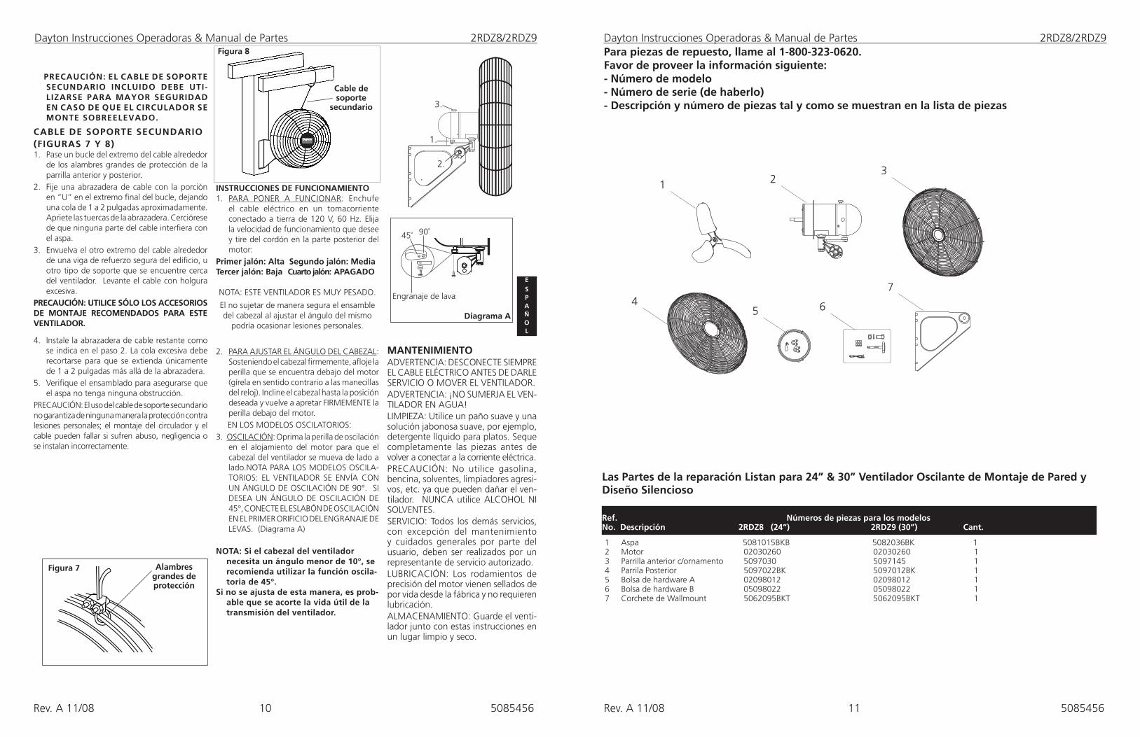
1 Aspa 5081015BKB 5082036BK 1 2 Motor 02030260 02030260 1 3 Parrilla anterior c/ornamento 5097030 5097145 14 Parrila Posterior 5097022BK 5097012BK 15 Bolsa de hardware A 02098012 02098012 16 Bolsa de hardware B 05098022 05098022 17 Corchete de Wallmount 5062095BKT 5062095BKT 1
2 Ref. Números de piezas para los modelosNo. Descripción 2RDZ8 (24”) 2RDZ9 (30”) Cant.
Para piezas de repuesto, llame al 1-800-323-0620.Favor de proveer la información siguiente:- Número de modelo- Número de serie (de haberlo)- Descripción y número de piezas tal y como se muestran en la lista de piezas
13
2
5 6
74


![[Word] Using Windows Server 2012 Essentials - We · PDF fileUsing&Windows&Server&2012&Essentials&–&Step&by ... outlet to document his experiences with this Microsoft ... Set up Anywhere](https://img.pdfslide.us/doc/110x75/5a78a9cb7f8b9ae91b8da04a/word-using-windows-server-2012-essentials-we-usingwindowsserver2012essentialsstepby.jpg)