Embed Size (px)
Citation preview
Junos® Networking Technologies
MPLS and MPLS applications can be
intimidating to Enterprise engineers,
especially if they are new to the Service
Provider world. This Day One book
makes it easier to understand how to
configure, verify, and troubleshoot the
basics of MPLS.
By Darren J. S. O’Connor
DAY ONE: MPLS FOR ENTERPRISE ENGINEERS

Juniper Networks Books are singularly focused on network productivity and efficiency. Peruse the complete library at www.juniper.net/books.
Published by Juniper Networks Books
DAY ONE: MPLS FOR ENTERPRISE ENGINEERS
There are many books on MPLS, even within the Day One library, but most are directed towards engineers with high levels of expertise and some networking engineers can get quite lost. This book takes a different tactic and focuses on configuring and recognizing MPLS basics, so those larger MPLS complexities seem less daunting.
Day One: MPLS for Enterprise Engineers is for engineers with at least a JNCIA-level of Junos, in addition to some IGP experience (BGP experience helps but is not essential). With this experience in hand, the reader should be able to build a few simple topologies in a lab and follow along with the book’s tutorial chapters.
Learning MPLS is key for enterprise engineers who are moving to, or working in Service Provider networks, and this Day One will allow you to understand what all those other MPLS books are saying. Start Here.
IT’S DAY ONE AND YOU HAVE A JOB TO DO, SO LEARN HOW TO: Better understand MPLS
Understand LDP and RSVP
Understand Labels
Deploy Layer 2 and Layer 3 services to your customers
Build a working model in your lab
“A superb book for getting straight into the heart of the subject matter that will have any-
one familiar with Junos up and running with MPLS in no time. Practical commands with a
thoughtful explanation of why each one is needed, backed up by detailed show commands
and real examples will give Enterprise engineers the confidence to play in the Service Pro-
vider space.”
Harry Lewins, Senior Networking Consultant,
JNCIS-SEC/FWV/ENT/SP, CCNP, CCIP. CNSE, BCNE
ISBN 978-1936779833
9 781936 779833
5 1 2 0 0

By Darren J. S. O'Connor
Day One: MPLS for Enterprise Engineers
Chapter 1: Why MPLS? . . . . . . . . . . . . . . . . . . . . . . . . . . . . . . . . . . . . . . . . . . . . . . . 7
Chapter 2: Label Distribution Protocols . . . . . . . . . . . . . . . . . . . . . . . . . . . . . . . .15
Chapter 3: Layer 3 VPN . . . . . . . . . . . . . . . . . . . . . . . . . . . . . . . . . . . . . . . . . . . . . . 43
Chapter 4: Layer 2 VPN . . . . . . . . . . . . . . . . . . . . . . . . . . . . . . . . . . . . . . . . . . . . . . 59
MPLS and MPLS applications can be intimidating to Enterprise engineers, especially if
they are new to the Service Provider world. This Day One book makes it easier to
understand how to configure, verify, and troubleshoot the basics of MPLS.

© 2014 by Juniper Networks, Inc. All rights reserved. Juniper Networks, Junos, Steel-Belted Radius, NetScreen, and ScreenOS are registered trademarks of Juniper Networks, Inc. in the United States and other countries. The Juniper Networks Logo, the Junos logo, and JunosE are trademarks of Juniper Networks, Inc. All other trademarks, service marks, registered trademarks, or registered service marks are the property of their respective owners. Juniper Networks assumes no responsibility for any inaccuracies in this document. Juniper Networks reserves the right to change, modify, transfer, or otherwise revise this publication without notice. Published by Juniper Networks BooksAuthor: Darren J. S. O’ConnorTechnical Reviewers: Krzysztof Grzegorz Szarkowicz, Tim Hoffman, Antonio-Sanchez MongeEditor in Chief: Patrick AmesCopyeditor and Proofer: Nancy KoerbelJ-Net Community Manager: Julie Wider
ISBN: 978-1-936779-83-3 (print)Printed in the USA by Vervante Corporation.
ISBN: 978-1-936779-84-0 (ebook)
Version History: v1, March 2014 2 3 4 5 6 7 8 9 10
This book is available in a variety of formats at: http://www.juniper.net/dayone.
About the Author Darren J. S. O’Connor is from Cape Town, South Africa, and is a Network Architect, certified JNCIE-SP #2227 and Dual CCIE #38070 (R/S - SP) - currently working for an ISP based in London, UK.
Author’s Acknowledgments I would like to thank my wife, Beatrix, for not getting too annoyed while I sat feverishly typing away on the laptop in the dark and talking about odd random things like router ids and so forth. For Köszi Babuci (that's Hungarian), I would like to thank my mother for always believing in me and telling me to do the best I can. I have not forgotten. I'd like to thank my two cats, Benjamin and Frederick, for the countless times they have walked over my laptop demanding attention while writing this book and during general studying. And of course I would like to thank Patrick, Nancy, Tim, Ato, and Krzysztof for looking over my work in order to complete this book.
iv

Welcome to Day One
This book is part of a growing library of Day One books, produced and published by Juniper Networks Books.
Day One books were conceived to help you get just the information that you need on day one. The series covers Junos OS and Juniper Networks networking essentials with straightforward explanations, step-by-step instructions, and practical examples that are easy to follow.
The Day One library also includes a slightly larger and longer suite of This Week books, whose concepts and test bed examples are more similar to a weeklong seminar.
You can obtain either series, in multiple formats:
� Download a free PDF edition at http://www.juniper.net/dayone.
� Get the ebook edition for iPhones and iPads from the iTunes Store. Search for Juniper Networks Books.
� Get the ebook edition for any device that runs the Kindle app (Android, Kindle, iPad, PC, or Mac) by opening your device's Kindle app and going to the Kindle Store. Search for Juniper Networks Books.
� Purchase the paper edition at either Vervante Corporation (www.vervante.com) or Amazon (amazon.com) for between $12-$28, depending on page length.
� Note that Nook, iPad, and various Android apps can also view PDF files.
Audience
This book is intended for enterprise network administrators moving into a service provider position and provides field-tested configurations for common network deployment scenarios, as well as brief background information needed to understand and deploy these solutions in your own environment.
The chapters in this book are arranged in a logical sequence to help you understand what MPLS is, how it’s configured, and how it helps you provide services to your customers.
v

vi
What You Need to Know Before Reading This Book
Before reading this Day One book, you should be familiar with the basic administrative functions of the Junos operating system, including the ability to work with operational commands and to read, understand, and change Junos configurations. There are several books in the Day One library on learning Junos, at www.juniper.net/dayone.
This book makes a few assumptions about you, the reader:
� You have a basic understanding of the Internet Protocol (IP) versions 4 and 6.
� You have a basic understanding of IGPs, especially OSPF
� You have a basic understanding of BGP
� You have access to a lab with at least the following components: one M/MX/T-Series router capable of logical-systems, or eight SRX devices in packet-mode.
What You Will Learn by Reading This Book
� Better understand MPLS.
� Understand LDP and RSVP
� Understand Labels
� Deploy Layer 2 and Layer 3 services to your customers
� Build a working model in your lab
Information Experience
There are other sources at Juniper Networks, from white papers to webinars to online forums such as J-Net (forums.juniper.net). Look for the following sidebars to directly access other superb resources:
MORE? It’s highly recommended you go through the technical documentation and the minimum requirements to get a sense of M/T/MX routers before you jump in. The technical documentation can be located at www.juniper.net/documentation. Use the “Explorer” tools on the documenta-tion site to explore and find the right information for your needs
7
This chapter briefly explains why the reader needs to learn MPLS when moving from Enterprise to Service Provider networking spaces, and why it is a best practice to run MPLS in the SP core.
NOTE MPLS brings with it some new terminology you should know. When looking at a network, the ISP edge routers are called PE routers (Provider Edge). Core ISP routers are called P routers (Provider). Finally routers on the customer premises, whether managed by the ISP or not, are called CE routers (Customer Edge). In other texts you may come across the terms LSR and LER – an LSR is a label switch router, i.e. any router that is actively switch-ing labeled packets, and an LER is an edge LSR. Generally a P router is an LSR, while a PE router would be an LER. Depending on the topology, a P/LSR router can also be a PE/LER at the same time for different LSPs. This Day One book simply uses the terms P for Provider and and PE for Provider Edge.
Core Network Challenges
Service Providers face unique challenges because their core busi-ness is providing network services to other businesses. Service Provider customers want to use part of the Service Provider network in order to connect with their own networks, and each one of these customers also wants to run their own private net-work, with overlapping address space, on top of the Service Provider core.
Of course, as you well know, the needs of each of these customers needs to be kept separate. Their customers, just like your older
Chapter 1
Why MPLS?
8 Day One:MPLS for Enterprise Engineers
Enterprise employers, want the ability to purchase both Layer 2 and Layer3 services from the same provider. And depending on the Service Provider customer, they may want the ability to push all 4094 available VLANs over the links provider. Who knows? Providing services is different than purchasing them, because as a provider, you must have it all in order to generate business.
As a Service Provider network, you may need the ability to have a direct link between two racks in a single Data Center, or 25 or more physical locations worldwide. A Provider might also have customers who are themselves Providers.
The point here is that MPLS allows all such activity to happen on a single network with relative ease. This book is meant for an Enterprise engineer moving into the Service Provider world. It answers the questions: What is MPLS? How do I best learn it, use it, configure it? All of these topics are explored in this Day One book, and as you shall see, MPLS also provides some abstraction to ensure that when engi-neers configure new services for customers, configuration is required on the routers connecting to the customer only (none at all is required on core routers).
To get started, let’s review some other key components of a MPLS-enabled network.
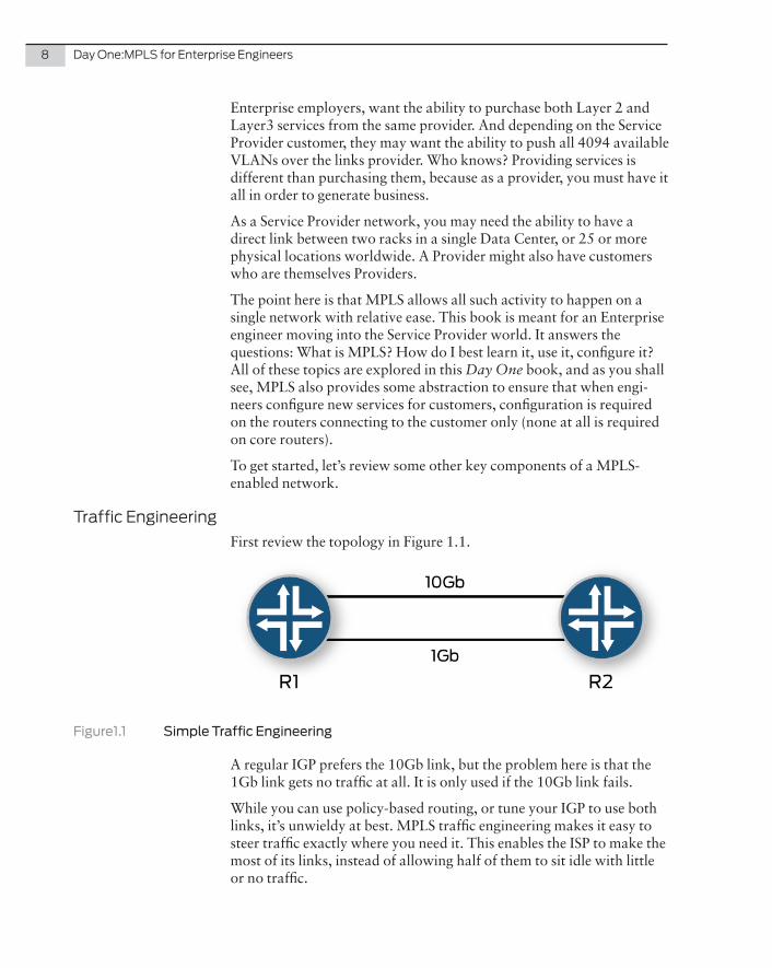
Traffic EngineeringFirst review the topology in Figure 1.1.
Figure1.1 Simple Traffic Engineering
A regular IGP prefers the 10Gb link, but the problem here is that the 1Gb link gets no traffic at all. It is only used if the 10Gb link fails.
While you can use policy-based routing, or tune your IGP to use both links, it’s unwieldy at best. MPLS traffic engineering makes it easy to steer traffic exactly where you need it. This enables the ISP to make the most of its links, instead of allowing half of them to sit idle with little or no traffic.
Chapter 1: Why MPLS? 9
Traffic Engineering greatly helps, for example, when doing core mainte-nance on your network, because you can steer traffic around links or routers that are to be taken out of service with zero packet loss. This allows your customers to achieve their coveted 99.999% uptime and you to maintain your large service provider network.
Fast Reroute
While traffic engineering can help with planned maintenance, MPLS also ensures rapid restoration of service after an unexpected outage. One of these features, named fast reroute, allows the core network to restore within 50 milliseconds of discovering a fault on the network. Fast reroute allows the core network to reroute MPLS-labeled paths without the majority of customers even noticing.
BGP-Free CoreService Providers require the full internet routing table in order to correctly route to all destinations on the internet. While line cards than can hold the entire global BGP table exist, they are expensive. With the advent of IPv6 this problem is even more difficult as each v6 prefix takes up to four times the amount of FIB space when compared to a v4 prefix.
MPLS allows you to run BGP only on the edge routers, so the core routers no longer need to have every prefix installed, as they only switch label traffic, allowing the Service Provider to buy cheaper, but very fast, routers for their core network.
The Label Switched PathIn essence, MPLS is all about switching traffic across a path using labels. Before it can begin, however, routers need to set up label-switched paths, from here on known as LSPs.
An easy way to think of an LSP is to understand that it’s essentially a tunnel. An edge router sets up an LSP to another edge router using MPLS. Traffic from edge router 1 to edge router 2 is sent across the network using labels, allowing edge router 1 and edge router 2 to send traffic to each other, without the core routers needing to know what kind of traffic is being sent. The only “routing” function performed by the core routers is performing a fixed-length lookup based on the label traffic is encapsu-lated in, then forwarding out another interface with a new label.
Figure 1.2 is a very simple diagram of two customers taking services from a Service Provider. Both customers have two offices that need to connect to each other, and both customers are using private RFC1918 address spaces on their respective LANs.
10 Day One:MPLS for Enterprise Engineers
º
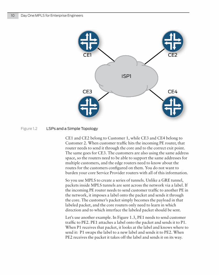
Figure 1.2 LSPs and a Simple Topology
CE1 and CE2 belong to Customer 1, while CE3 and CE4 belong to Customer 2. When customer traffic hits the incoming PE router, that router needs to send it through the core and to the correct exit point. The same goes for CE3. The customers are also using the same address space, so the routers need to be able to support the same addresses for multiple customers, and the edge routers need to know about the routes for the customers configured on them. You do not want to burden your core Service Provider routers with all of this information.
So you use MPLS to create a series of tunnels. Unlike a GRE tunnel, packets inside MPLS tunnels are sent across the network via a label. If the incoming PE router needs to send customer traffic to another PE in the network, it imposes a label onto the packet and sends it through the core. The customer’s packet simply becomes the payload in that labeled packet, and the core routers only need to learn in which direction and to which interface the labeled packet should be sent.
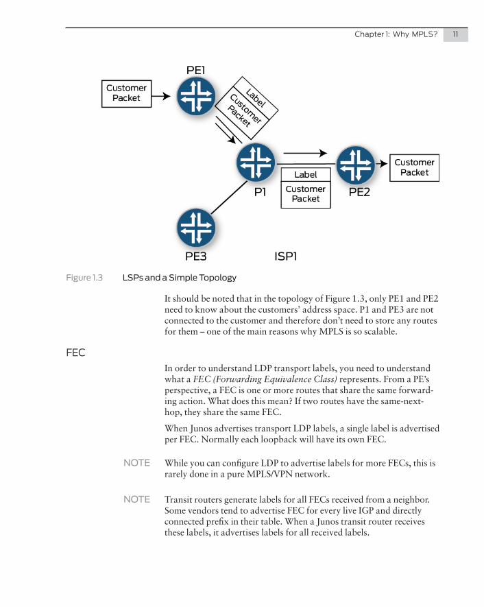
Let’s use another example. In Figure 1.3, PE1 needs to send customer traffic to PE2. PE1 attaches a label onto the packet and sends it to P1. When P1 receives that packet, it looks at the label and knows where to send it: P1 swaps the label to a new label and sends it to PE2. When PE2 receives the packet it takes off the label and sends it on its way.
Chapter 1: Why MPLS? 11
Figure 1.3 LSPs and a Simple Topology
It should be noted that in the topology of Figure 1.3, only PE1 and PE2 need to know about the customers’ address space. P1 and PE3 are not connected to the customer and therefore don’t need to store any routes for them – one of the main reasons why MPLS is so scalable.
FECIn order to understand LDP transport labels, you need to understand what a FEC (Forwarding Equivalence Class) represents. From a PE’s perspective, a FEC is one or more routes that share the same forward-ing action. What does this mean? If two routes have the same-next-hop, they share the same FEC.
When Junos advertises transport LDP labels, a single label is advertised per FEC. Normally each loopback will have its own FEC.
NOTE While you can configure LDP to advertise labels for more FECs, this is rarely done in a pure MPLS/VPN network.
NOTE Transit routers generate labels for all FECs received from a neighbor. Some vendors tend to advertise FEC for every live IGP and directly connected prefix in their table. When a Junos transit router receives these labels, it advertises labels for all received labels.
12 Day One:MPLS for Enterprise Engineers
VC/VPN LabelsThe LSP in Figure 1.3 is used to transport traffic from PE1 to PE2. Once a packet gets to PE2, PE2 needs to know which customer that packet belongs to. The transport label only gets the packet to PE2, but it doesn’t tell PE2 which VPN/VC it belongs to.
Therefore PE routers signal a second label typically called the VPN, VC, or service label. This second label is advertised via a separate process as the one that produces the transport label. The VPN/VC label sits under the transport label in the frame across the MPLS core. Only the PEs care about the VPN/VC label – core routers look only at the topmost transport label.
NOTE Transport labels are signaled via RSVP, LDP, or BGP labeled unicast. VPN/VC labels are advertised via BGP or targeted LDP. It’s important to note that the VPN/VC signaling is a completely separate process from the transport label signaling, therefore, if you’re using LDP for transport, the router learns LDP transport labels directly through its LDP neighbors, while it learns the VPN/VC labels through the targeted LDP session with the remote PE router.
Penultimate Hop-popping (PHP)By default, transport label bindings are signaled with an implicit-null on the last-hop. This means then when a P router sends a frame to the final PE router, the transport label is stripped off. This prevents the PE router from having to do two label lookups and an IP lookup. You can configure the PE routers with an explicit-null statement, which ensures that transport labels are only popped by the final PE router, not by the second-to-last P router.
NOTE Only transport labels undergo penultimate hop-popping. VPN/VC labels are required by the final PE router and so never undergo the PHP process.
How Junos Uses LSPs
Inet.0 is the main routing table in Junos. If Junos needs to forward an IP packet, the inet.0 table determines where that packet should be going.
When MPLS is properly configured, Junos, by default, places the loopback address of the LSP egress router into the inet.3 routing table. (BGP prefers to use this table first when resolving a next-hop IP, but you can change this to also let the IGP use it if you wish.)
Chapter 1: Why MPLS? 13
Junos creates a mpls.0 table containing the labels that the local router uses to switch traffic. These tables are covered in more detail in Chapter 2 of this Day One book.
TIP Junos also gives you the ability to add additional egress prefixes into inet.3, if that is needed.
Packet Format
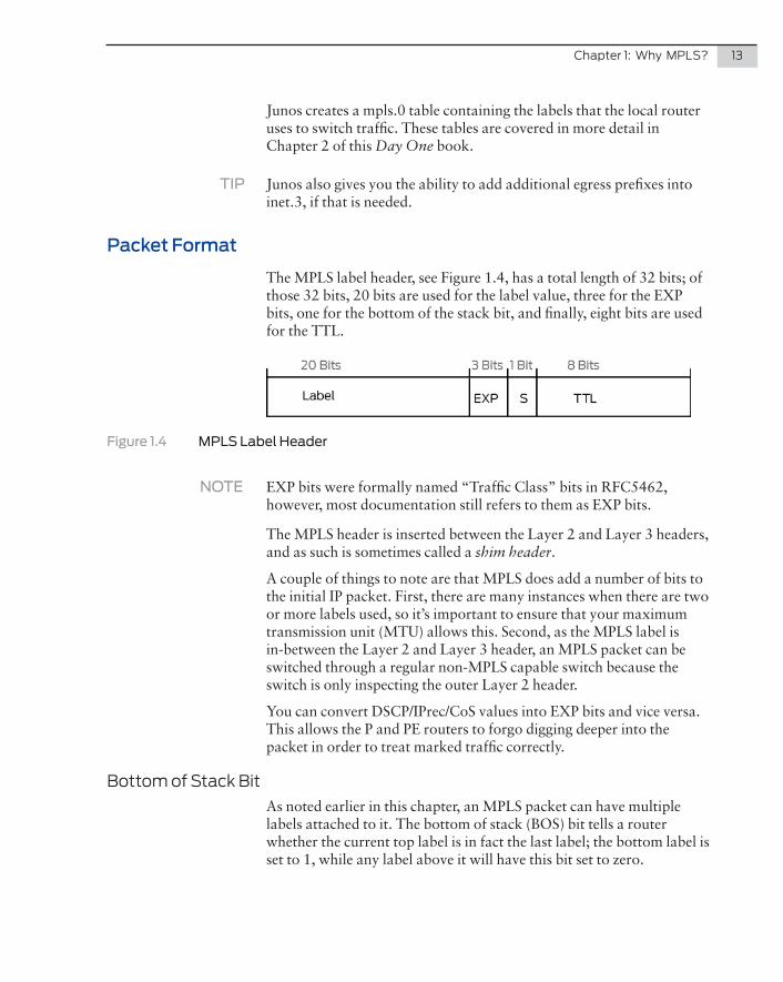
The MPLS label header, see Figure 1.4, has a total length of 32 bits; of those 32 bits, 20 bits are used for the label value, three for the EXP bits, one for the bottom of the stack bit, and finally, eight bits are used for the TTL.
Figure 1.4 MPLS Label Header
NOTE EXP bits were formally named “Traffic Class” bits in RFC5462, however, most documentation still refers to them as EXP bits.
The MPLS header is inserted between the Layer 2 and Layer 3 headers, and as such is sometimes called a shim header.
A couple of things to note are that MPLS does add a number of bits to the initial IP packet. First, there are many instances when there are two or more labels used, so it’s important to ensure that your maximum transmission unit (MTU) allows this. Second, as the MPLS label is in-between the Layer 2 and Layer 3 header, an MPLS packet can be switched through a regular non-MPLS capable switch because the switch is only inspecting the outer Layer 2 header.
You can convert DSCP/IPrec/CoS values into EXP bits and vice versa. This allows the P and PE routers to forgo digging deeper into the packet in order to treat marked traffic correctly.
Bottom of Stack BitAs noted earlier in this chapter, an MPLS packet can have multiple labels attached to it. The bottom of stack (BOS) bit tells a router whether the current top label is in fact the last label; the bottom label is set to 1, while any label above it will have this bit set to zero.
14 Day One:MPLS for Enterprise Engineers
TTL
While the underlying packet has its own time to live (TTL), the label also has its own TTL. With MPLS you can have the option of copying the TTL value of the original packet into the MPLS packet and vice-versa, or the MPLS packet could have its own TTL start at 255 while the underlying packet is not touched until egress. This manipulation allows the Service Provider to either show or hide its internal topology when customers are tracerouting from their CE routers.
Summary
First, we offer our apologies to the many networking authors, engi-neers, and architects who have written about MPLS in books, white papers, and discussion boards over the past decade. These publica-tions have all been superb, and you have documented and helped develop one of the key networking technologies of the 21st century. However, our readers have just covered MPLS concepts in about four pages, and several particulars were skipped along the way.
There is no shortage of reading material on MPLS. You can shop the Day One library, Juniper Technical Documentation, O’Reilly books, and a hundred web sites and certification sites for more information about it. You are encouraged to do so.
The rest of the exercises in this book can be recreated in your own lab so try them as you follow along.
15
To begin our exploration of MPLS, let’s jump right in and config-ure LDP and RSVP, the protocols that will enable MPLS in our core network.
Let’s start with LDP – it’s easier to configure and you get some control over your LSP paths. You’ll see that RSVP gives you a lot more control, but it takes longer to configure and introduces more state in the control plane.
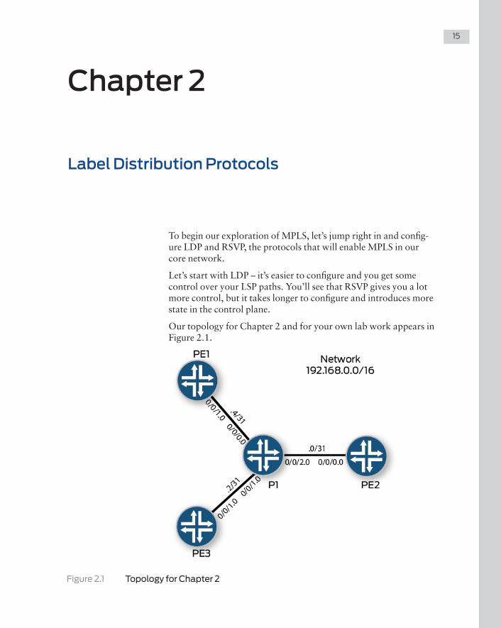
Our topology for Chapter 2 and for your own lab work appears in Figure 2.1.
Figure 2.1 Topology for Chapter 2
Chapter 2
Label Distribution Protocols
16 Day One: MPLS for Enterprise Engineers
Configuring LDP
P router
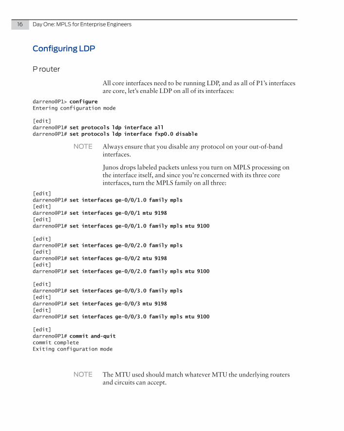
All core interfaces need to be running LDP, and as all of P1’s interfaces are core, let’s enable LDP on all of its interfaces:
darreno@P1> configureEntering configuration mode
[edit]darreno@P1# set protocols ldp interface alldarreno@P1# set protocols ldp interface fxp0.0 disable
NOTE Always ensure that you disable any protocol on your out-of-band interfaces.
Junos drops labeled packets unless you turn on MPLS processing on the interface itself, and since you’re concerned with its three core interfaces, turn the MPLS family on all three:
[edit]darreno@P1# set interfaces ge-0/0/1.0 family mpls[edit]darreno@P1# set interfaces ge-0/0/1 mtu 9198[edit]darreno@P1# set interfaces ge-0/0/1.0 family mpls mtu 9100
[edit]darreno@P1# set interfaces ge-0/0/2.0 family mpls[edit]darreno@P1# set interfaces ge-0/0/2 mtu 9198[edit]darreno@P1# set interfaces ge-0/0/2.0 family mpls mtu 9100
[edit]darreno@P1# set interfaces ge-0/0/3.0 family mpls[edit]darreno@P1# set interfaces ge-0/0/3 mtu 9198[edit]darreno@P1# set interfaces ge-0/0/3.0 family mpls mtu 9100
[edit]darreno@P1# commit and-quitcommit completeExiting configuration mode
NOTE The MTU used should match whatever MTU the underlying routers and circuits can accept.
Chapter 2: Label Distribution Protocols 17
PE routers
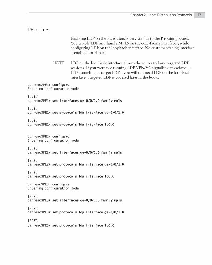
Enabling LDP on the PE routers is very similar to the P router process. You enable LDP and family MPLS on the core-facing interfaces, while configuring LDP on the loopback interface. No customer-facing interface is enabled for either.
NOTE LDP on the loopback interface allows the router to have targeted LDP sessions. If you were not running LDP VPN/VC signalling anywhere—LDP tunneling or target LDP – you will not need LDP on the loopback interface. Targeted LDP is covered later in the book.
darreno@PE1> configureEntering configuration mode
[edit]darreno@PE1# set interfaces ge-0/0/1.0 family mpls
[edit]darreno@PE1# set protocols ldp interface ge-0/0/1.0
[edit]darreno@PE1# set protocols ldp interface lo0.0
darreno@PE2> configureEntering configuration mode
[edit]darreno@PE2# set interfaces ge-0/0/1.0 family mpls
[edit]darreno@PE2# set protocols ldp interface ge-0/0/1.0
[edit]darreno@PE2# set protocols ldp interface lo0.0
darreno@PE3> configureEntering configuration mode
[edit]darreno@PE3# set interfaces ge-0/0/1.0 family mpls
[edit]darreno@PE3# set protocols ldp interface ge-0/0/1.0
[edit]
darreno@PE3# set protocols ldp interface lo0.0
18 Day One: MPLS for Enterprise Engineers
Verifying LDP
LDP Neighbor
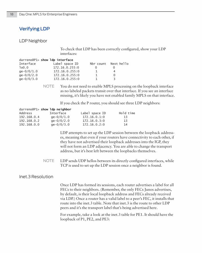
To check that LDP has been correctly configured, show your LDP interfaces:
darreno@P1> show ldp interfaceInterface Label space ID Nbr count Next hellolo0.0 172.16.0.255:0 0 0ge-0/0/1.0 172.16.0.255:0 1 4ge-0/0/2.0 172.16.0.255:0 1 0ge-0/0/3.0 172.16.0.255:0 1 3
NOTE You do not need to enable MPLS processing on the loopback interface as no labeled packets transit over that interface. If you see an interface missing, it’s likely you have not enabled family MPLS on that interface.
If you check the P router, you should see three LDP neighbors:
darreno@P1> show ldp neighborAddress Interface Label space ID Hold time192.168.0.4 ge-0/0/1.0 172.16.0.1:0 13192.168.0.2 ge-0/0/2.0 172.16.0.3:0 13192.168.0.0 ge-0/0/3.0 172.16.0.2:0 14
LDP attempts to set up the LDP session between the loopback address-es, meaning that even if your routers have connectivity to each other, if they have not advertised their loopback addresses into the IGP, they will not form an LDP adjacency. You are able to change the transport address, but it’s best left between the loopbacks themselves.
NOTE LDP sends UDP hellos between its directly configured interfaces, while TCP is used to set up the LDP session once a neighbor is found.
Inet.3 Resolution
Once LDP has formed its sessions, each router advertises a label for all FECs to their neighbors. (Remember, the only FECs Junos advertises, by default, is their local loopback address and FECs already received via LDP.) Once a router has a valid label to a peer’s FEC, it installs that route into the inet.3 table. Note that inet.3 is the route to other LDP peers and it’s the transport label that’s being advertised here.
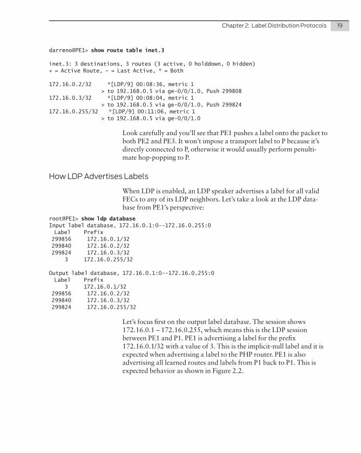
For example, take a look at the inet.3 table for PE1. It should have the loopback of P1, PE2, and PE3:
Chapter 2: Label Distribution Protocols 19
darreno@PE1> show route table inet.3
inet.3: 3 destinations, 3 routes (3 active, 0 holddown, 0 hidden)+ = Active Route, - = Last Active, * = Both
172.16.0.2/32 *[LDP/9] 00:08:36, metric 1 > to 192.168.0.5 via ge-0/0/1.0, Push 299808172.16.0.3/32 *[LDP/9] 00:08:04, metric 1 > to 192.168.0.5 via ge-0/0/1.0, Push 299824172.16.0.255/32 *[LDP/9] 00:11:06, metric 1 > to 192.168.0.5 via ge-0/0/1.0
Look carefully and you’ll see that PE1 pushes a label onto the packet to both PE2 and PE3. It won’t impose a transport label to P because it’s directly connected to P, otherwise it would usually perform penulti-mate hop-popping to P.
How LDP Advertises Labels
When LDP is enabled, an LDP speaker advertises a label for all valid FECs to any of its LDP neighbors. Let’s take a look at the LDP data-base from PE1’s perspective:
root@PE1> show ldp databaseInput label database, 172.16.0.1:0--172.16.0.255:0 Label Prefix 299856 172.16.0.1/32 299840 172.16.0.2/32 299824 172.16.0.3/32 3 172.16.0.255/32
Output label database, 172.16.0.1:0--172.16.0.255:0 Label Prefix 3 172.16.0.1/32 299856 172.16.0.2/32 299840 172.16.0.3/32 299824 172.16.0.255/32
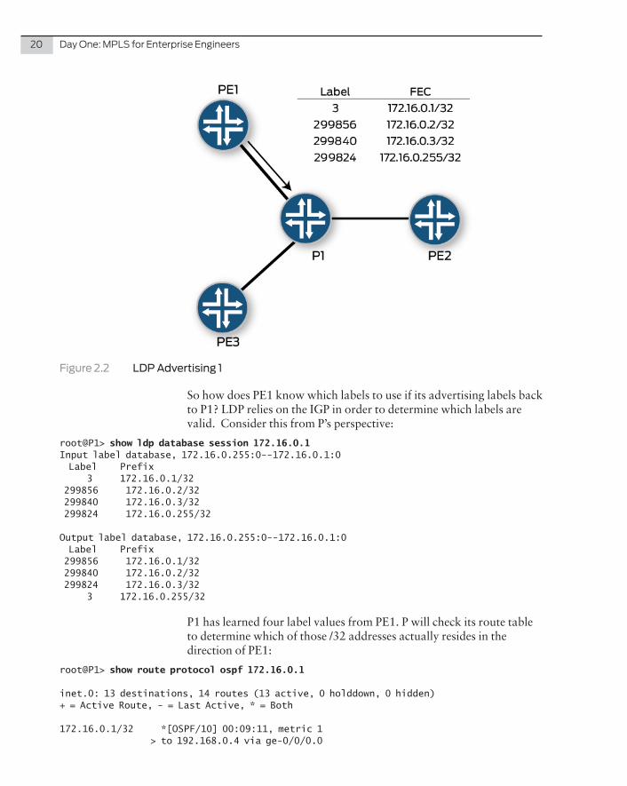
Let’s focus first on the output label database. The session shows 172.16.0.1 – 172.16.0.255, which means this is the LDP session between PE1 and P1. PE1 is advertising a label for the prefix 172.16.0.1/32 with a value of 3. This is the implicit-null label and it is expected when advertising a label to the PHP router. PE1 is also advertising all learned routes and labels from P1 back to P1. This is expected behavior as shown in Figure 2.2.
20 Day One: MPLS for Enterprise Engineers
Figure 2.2 LDP Advertising 1
So how does PE1 know which labels to use if its advertising labels back to P1? LDP relies on the IGP in order to determine which labels are valid. Consider this from P’s perspective:
root@P1> show ldp database session 172.16.0.1Input label database, 172.16.0.255:0--172.16.0.1:0 Label Prefix 3 172.16.0.1/32 299856 172.16.0.2/32 299840 172.16.0.3/32 299824 172.16.0.255/32
Output label database, 172.16.0.255:0--172.16.0.1:0 Label Prefix 299856 172.16.0.1/32 299840 172.16.0.2/32 299824 172.16.0.3/32 3 172.16.0.255/32
P1 has learned four label values from PE1. P will check its route table to determine which of those /32 addresses actually resides in the direction of PE1:
root@P1> show route protocol ospf 172.16.0.1
inet.0: 13 destinations, 14 routes (13 active, 0 holddown, 0 hidden)+ = Active Route, - = Last Active, * = Both
172.16.0.1/32 *[OSPF/10] 00:09:11, metric 1 > to 192.168.0.4 via ge-0/0/0.0
Chapter 2: Label Distribution Protocols 21
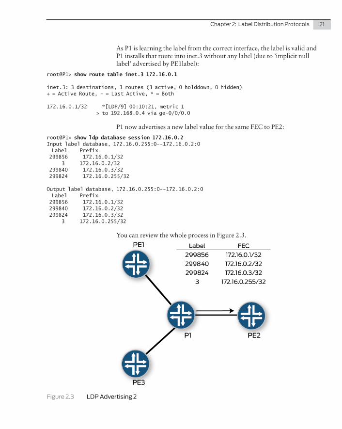
As P1 is learning the label from the correct interface, the label is valid and P1 installs that route into inet.3 without any label (due to ’implicit null label’ advertised by PE1label):
root@P1> show route table inet.3 172.16.0.1
inet.3: 3 destinations, 3 routes (3 active, 0 holddown, 0 hidden)+ = Active Route, - = Last Active, * = Both
172.16.0.1/32 *[LDP/9] 00:10:21, metric 1 > to 192.168.0.4 via ge-0/0/0.0
P1 now advertises a new label value for the same FEC to PE2:
root@P1> show ldp database session 172.16.0.2Input label database, 172.16.0.255:0--172.16.0.2:0 Label Prefix 299856 172.16.0.1/32 3 172.16.0.2/32 299840 172.16.0.3/32 299824 172.16.0.255/32
Output label database, 172.16.0.255:0--172.16.0.2:0 Label Prefix 299856 172.16.0.1/32 299840 172.16.0.2/32 299824 172.16.0.3/32 3 172.16.0.255/32
You can review the whole process in Figure 2.3.
Figure 2.3 LDP Advertising 2
22 Day One: MPLS for Enterprise Engineers
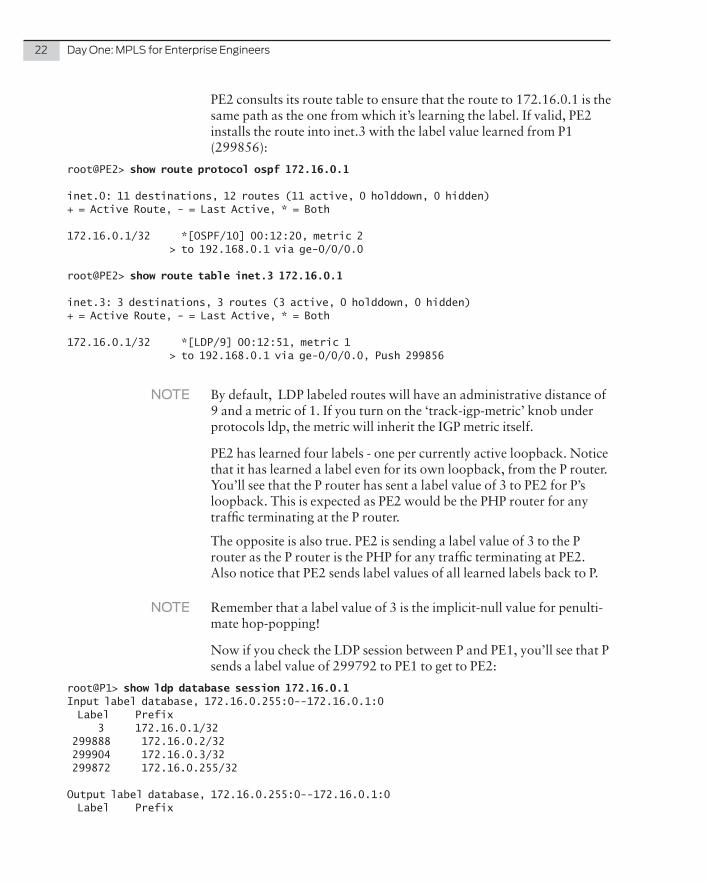
PE2 consults its route table to ensure that the route to 172.16.0.1 is the same path as the one from which it’s learning the label. If valid, PE2 installs the route into inet.3 with the label value learned from P1 (299856):
root@PE2> show route protocol ospf 172.16.0.1
inet.0: 11 destinations, 12 routes (11 active, 0 holddown, 0 hidden)+ = Active Route, - = Last Active, * = Both
172.16.0.1/32 *[OSPF/10] 00:12:20, metric 2 > to 192.168.0.1 via ge-0/0/0.0
root@PE2> show route table inet.3 172.16.0.1
inet.3: 3 destinations, 3 routes (3 active, 0 holddown, 0 hidden)+ = Active Route, - = Last Active, * = Both
172.16.0.1/32 *[LDP/9] 00:12:51, metric 1 > to 192.168.0.1 via ge-0/0/0.0, Push 299856
NOTE By default, LDP labeled routes will have an administrative distance of 9 and a metric of 1. If you turn on the ‘track-igp-metric’ knob under protocols ldp, the metric will inherit the IGP metric itself.
PE2 has learned four labels - one per currently active loopback. Notice that it has learned a label even for its own loopback, from the P router. You’ll see that the P router has sent a label value of 3 to PE2 for P’s loopback. This is expected as PE2 would be the PHP router for any traffic terminating at the P router.
The opposite is also true. PE2 is sending a label value of 3 to the P router as the P router is the PHP for any traffic terminating at PE2. Also notice that PE2 sends label values of all learned labels back to P.
NOTE Remember that a label value of 3 is the implicit-null value for penulti-mate hop-popping!
Now if you check the LDP session between P and PE1, you’ll see that P sends a label value of 299792 to PE1 to get to PE2:
root@P1> show ldp database session 172.16.0.1Input label database, 172.16.0.255:0--172.16.0.1:0 Label Prefix 3 172.16.0.1/32 299888 172.16.0.2/32 299904 172.16.0.3/32 299872 172.16.0.255/32
Output label database, 172.16.0.255:0--172.16.0.1:0 Label Prefix
Chapter 2: Label Distribution Protocols 23
299840 172.16.0.1/32 299792 172.16.0.2/32 299808 172.16.0.3/32 3 172.16.0.255/32
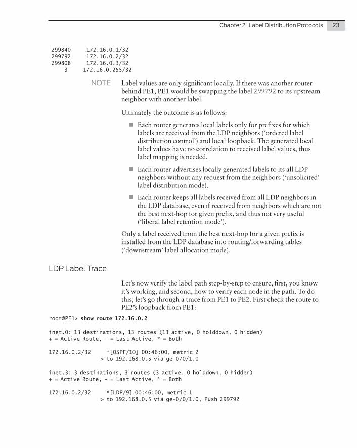
NOTE Label values are only significant locally. If there was another router behind PE1, PE1 would be swapping the label 299792 to its upstream neighbor with another label.
Ultimately the outcome is as follows:
� Each router generates local labels only for prefixes for which labels are received from the LDP neighbors (‘ordered label distribution control’) and local loopback. The generated local label values have no correlation to received label values, thus label mapping is needed.
� Each router advertises locally generated labels to its all LDP neighbors without any request from the neighbors (‘unsolicited’ label distribution mode).
� Each router keeps all labels received from all LDP neighbors in the LDP database, even if received from neighbors which are not the best next-hop for given prefix, and thus not very useful (‘liberal label retention mode’).
Only a label received from the best next-hop for a given prefix is installed from the LDP database into routing/forwarding tables (’downstream’ label allocation mode).
LDP Label Trace
Let’s now verify the label path step-by-step to ensure, first, you know it’s working, and second, how to verify each node in the path. To do this, let’s go through a trace from PE1 to PE2. First check the route to PE2’s loopback from PE1:
root@PE1> show route 172.16.0.2
inet.0: 13 destinations, 13 routes (13 active, 0 holddown, 0 hidden)+ = Active Route, - = Last Active, * = Both
172.16.0.2/32 *[OSPF/10] 00:46:00, metric 2 > to 192.168.0.5 via ge-0/0/1.0
inet.3: 3 destinations, 3 routes (3 active, 0 holddown, 0 hidden)+ = Active Route, - = Last Active, * = Both
172.16.0.2/32 *[LDP/9] 00:46:00, metric 1 > to 192.168.0.5 via ge-0/0/1.0, Push 299792
24 Day One: MPLS for Enterprise Engineers
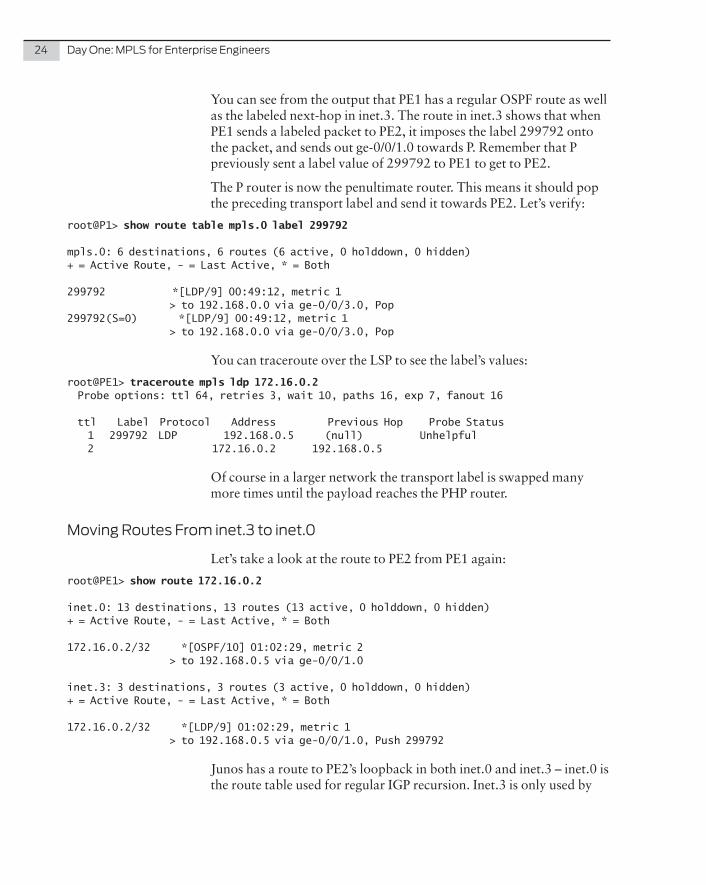
You can see from the output that PE1 has a regular OSPF route as well as the labeled next-hop in inet.3. The route in inet.3 shows that when PE1 sends a labeled packet to PE2, it imposes the label 299792 onto the packet, and sends out ge-0/0/1.0 towards P. Remember that P previously sent a label value of 299792 to PE1 to get to PE2.
The P router is now the penultimate router. This means it should pop the preceding transport label and send it towards PE2. Let’s verify:
root@P1> show route table mpls.0 label 299792
mpls.0: 6 destinations, 6 routes (6 active, 0 holddown, 0 hidden)+ = Active Route, - = Last Active, * = Both
299792 *[LDP/9] 00:49:12, metric 1 > to 192.168.0.0 via ge-0/0/3.0, Pop299792(S=0) *[LDP/9] 00:49:12, metric 1 > to 192.168.0.0 via ge-0/0/3.0, Pop
You can traceroute over the LSP to see the label’s values:
root@PE1> traceroute mpls ldp 172.16.0.2 Probe options: ttl 64, retries 3, wait 10, paths 16, exp 7, fanout 16
ttl Label Protocol Address Previous Hop Probe Status 1 299792 LDP 192.168.0.5 (null) Unhelpful 2 172.16.0.2 192.168.0.5
Of course in a larger network the transport label is swapped many more times until the payload reaches the PHP router.
Moving Routes From inet.3 to inet.0
Let’s take a look at the route to PE2 from PE1 again:
root@PE1> show route 172.16.0.2
inet.0: 13 destinations, 13 routes (13 active, 0 holddown, 0 hidden)+ = Active Route, - = Last Active, * = Both
172.16.0.2/32 *[OSPF/10] 01:02:29, metric 2 > to 192.168.0.5 via ge-0/0/1.0
inet.3: 3 destinations, 3 routes (3 active, 0 holddown, 0 hidden)+ = Active Route, - = Last Active, * = Both
172.16.0.2/32 *[LDP/9] 01:02:29, metric 1 > to 192.168.0.5 via ge-0/0/1.0, Push 299792
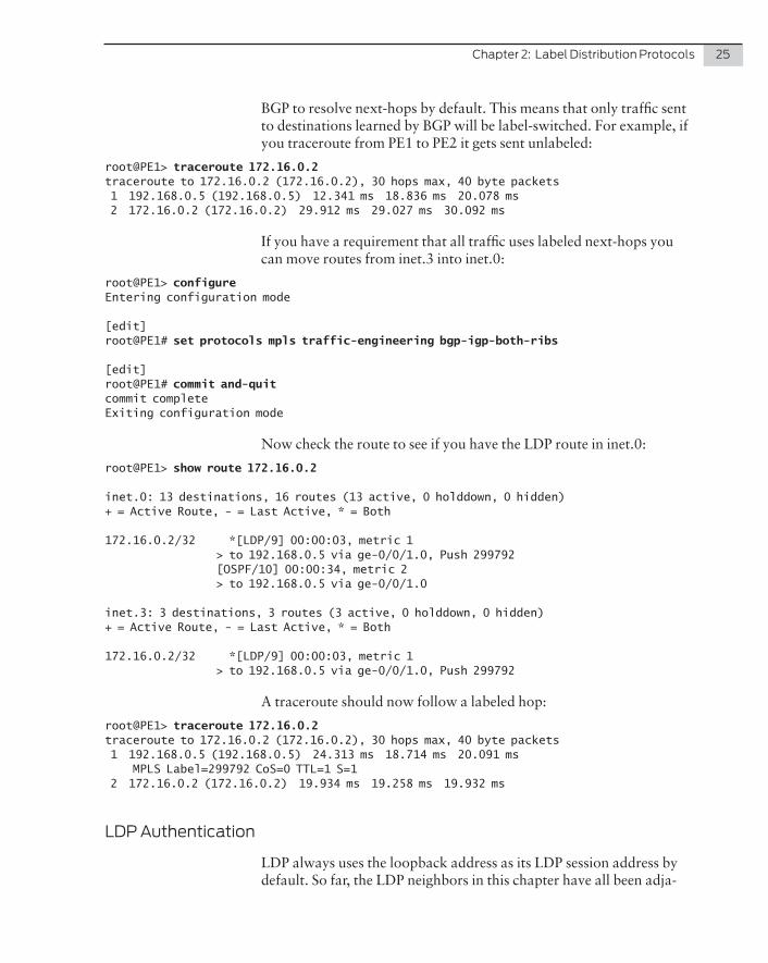
Junos has a route to PE2’s loopback in both inet.0 and inet.3 – inet.0 is the route table used for regular IGP recursion. Inet.3 is only used by
Chapter 2: Label Distribution Protocols 25
BGP to resolve next-hops by default. This means that only traffic sent to destinations learned by BGP will be label-switched. For example, if you traceroute from PE1 to PE2 it gets sent unlabeled:
root@PE1> traceroute 172.16.0.2traceroute to 172.16.0.2 (172.16.0.2), 30 hops max, 40 byte packets 1 192.168.0.5 (192.168.0.5) 12.341 ms 18.836 ms 20.078 ms 2 172.16.0.2 (172.16.0.2) 29.912 ms 29.027 ms 30.092 ms
If you have a requirement that all traffic uses labeled next-hops you can move routes from inet.3 into inet.0:
root@PE1> configureEntering configuration mode
[edit]root@PE1# set protocols mpls traffic-engineering bgp-igp-both-ribs
[edit]root@PE1# commit and-quitcommit completeExiting configuration mode
Now check the route to see if you have the LDP route in inet.0:
root@PE1> show route 172.16.0.2
inet.0: 13 destinations, 16 routes (13 active, 0 holddown, 0 hidden)+ = Active Route, - = Last Active, * = Both
172.16.0.2/32 *[LDP/9] 00:00:03, metric 1 > to 192.168.0.5 via ge-0/0/1.0, Push 299792 [OSPF/10] 00:00:34, metric 2 > to 192.168.0.5 via ge-0/0/1.0
inet.3: 3 destinations, 3 routes (3 active, 0 holddown, 0 hidden)+ = Active Route, - = Last Active, * = Both
172.16.0.2/32 *[LDP/9] 00:00:03, metric 1 > to 192.168.0.5 via ge-0/0/1.0, Push 299792
A traceroute should now follow a labeled hop:
root@PE1> traceroute 172.16.0.2traceroute to 172.16.0.2 (172.16.0.2), 30 hops max, 40 byte packets 1 192.168.0.5 (192.168.0.5) 24.313 ms 18.714 ms 20.091 ms MPLS Label=299792 CoS=0 TTL=1 S=1 2 172.16.0.2 (172.16.0.2) 19.934 ms 19.258 ms 19.932 ms
LDP Authentication
LDP always uses the loopback address as its LDP session address by default. So far, the LDP neighbors in this chapter have all been adja-
26 Day One: MPLS for Enterprise Engineers
cent, although the actual LDP session is created between the loopback addresses of the adjacent router. Note that this has nothing to do with targeted LDP sessions.
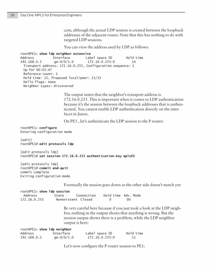
You can view the address used by LDP as follows:
root@PE1> show ldp neighbor extensiveAddress Interface Label space ID Hold time192.168.0.5 ge-0/0/1.0 172.16.0.255:0 14 Transport address: 172.16.0.255, Configuration sequence: 1 Up for 00:05:47 Reference count: 1 Hold time: 15, Proposed local/peer: 15/15 Hello flags: none Neighbor types: discovered
The output states that the neighbor’s transport address is 172.16.0.255. This is important when it comes to LDP authentication because it’s the session between the loopback addresses that is authen-ticated. You cannot enable LDP authentication directly on the inter-faces in Junos.
On PE1 , let’s authenticate the LDP session to the P router:
root@PE1> configureEntering configuration mode
[edit]root@PE1# edit protocols ldp
[edit protocols ldp]root@PE1# set session 172.16.0.255 authentication-key mplsEE
[edit protocols ldp]root@PE1# commit and-quitcommit completeExiting configuration mode
Eventually the session goes down as the other side doesn’t match yet:
root@PE1> show ldp session Address State Connection Hold time Adv. Mode172.16.0.255 Nonexistent Closed 0 DU
Be very careful here because if you just took a look at the LDP neigh-bor, nothing in the output shows that anything is wrong. But the session output shows there is a problem, while the LDP neighbor output is here:
root@PE1> show ldp neighborAddress Interface Label space ID Hold time192.168.0.5 ge-0/0/1.0 172.16.0.255:0 11
Let’s now configure the P router session to PE1:
Chapter 2: Label Distribution Protocols 27
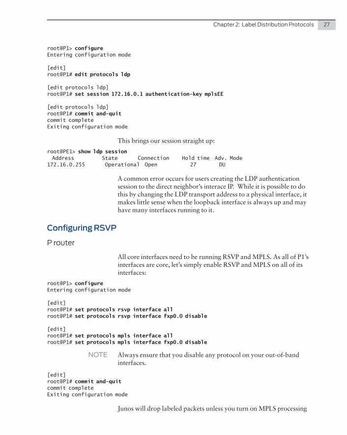
root@P1> configureEntering configuration mode
[edit]root@P1# edit protocols ldp
[edit protocols ldp]root@P1# set session 172.16.0.1 authentication-key mplsEE
[edit protocols ldp]root@P1# commit and-quitcommit completeExiting configuration mode
This brings our session straight up:
root@PE1> show ldp session Address State Connection Hold time Adv. Mode172.16.0.255 Operational Open 27 DU
A common error occurs for users creating the LDP authentication session to the direct neighbor’s interace IP. While it is possible to do this by changing the LDP transport address to a physical interface, it makes little sense when the loopback interface is always up and may have many interfaces running to it.
Configuring RSVP
P router
All core interfaces need to be running RSVP and MPLS. As all of P1’s interfaces are core, let’s simply enable RSVP and MPLS on all of its interfaces:
root@P1> configureEntering configuration mode
[edit]root@P1# set protocols rsvp interface allroot@P1# set protocols rsvp interface fxp0.0 disable
[edit]root@P1# set protocols mpls interface allroot@P1# set protocols mpls interface fxp0.0 disable
NOTE Always ensure that you disable any protocol on your out-of-band interfaces.
[edit]root@P1# commit and-quitcommit completeExiting configuration mode
Junos will drop labeled packets unless you turn on MPLS processing
28 Day One: MPLS for Enterprise Engineers
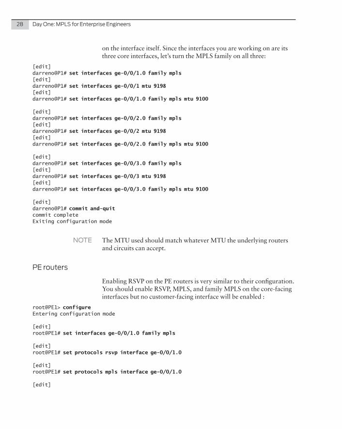
on the interface itself. Since the interfaces you are working on are its three core interfaces, let’s turn the MPLS family on all three:
[edit]darreno@P1# set interfaces ge-0/0/1.0 family mpls[edit]darreno@P1# set interfaces ge-0/0/1 mtu 9198[edit]darreno@P1# set interfaces ge-0/0/1.0 family mpls mtu 9100
[edit]darreno@P1# set interfaces ge-0/0/2.0 family mpls[edit]darreno@P1# set interfaces ge-0/0/2 mtu 9198[edit]darreno@P1# set interfaces ge-0/0/2.0 family mpls mtu 9100
[edit]darreno@P1# set interfaces ge-0/0/3.0 family mpls[edit]darreno@P1# set interfaces ge-0/0/3 mtu 9198[edit]darreno@P1# set interfaces ge-0/0/3.0 family mpls mtu 9100
[edit]darreno@P1# commit and-quitcommit completeExiting configuration mode
NOTE The MTU used should match whatever MTU the underlying routers and circuits can accept.
PE routers
Enabling RSVP on the PE routers is very similar to their configuration. You should enable RSVP, MPLS, and family MPLS on the core-facing interfaces but no customer-facing interface will be enabled :
root@PE1> configureEntering configuration mode
[edit]root@PE1# set interfaces ge-0/0/1.0 family mpls
[edit]root@PE1# set protocols rsvp interface ge-0/0/1.0
[edit]root@PE1# set protocols mpls interface ge-0/0/1.0
[edit]
Chapter 2: Label Distribution Protocols 29
root@PE1# commit and-quitcommit completeExiting configuration mode
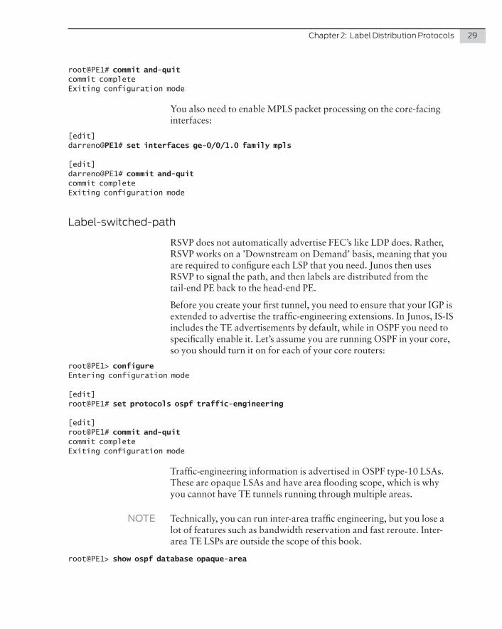
You also need to enable MPLS packet processing on the core-facing interfaces:
[edit]darreno@PE1# set interfaces ge-0/0/1.0 family mpls
[edit]darreno@PE1# commit and-quitcommit completeExiting configuration mode
Label-switched-path
RSVP does not automatically advertise FEC’s like LDP does. Rather, RSVP works on a ’Downstream on Demand’ basis, meaning that you are required to configure each LSP that you need. Junos then uses RSVP to signal the path, and then labels are distributed from the tail-end PE back to the head-end PE.
Before you create your first tunnel, you need to ensure that your IGP is extended to advertise the traffic-engineering extensions. In Junos, IS-IS includes the TE advertisements by default, while in OSPF you need to specifically enable it. Let’s assume you are running OSPF in your core, so you should turn it on for each of your core routers:
root@PE1> configureEntering configuration mode
[edit]root@PE1# set protocols ospf traffic-engineering
[edit]root@PE1# commit and-quitcommit completeExiting configuration mode
Traffic-engineering information is advertised in OSPF type-10 LSAs. These are opaque LSAs and have area flooding scope, which is why you cannot have TE tunnels running through multiple areas.
NOTE Technically, you can run inter-area traffic engineering, but you lose a lot of features such as bandwidth reservation and fast reroute. Inter-area TE LSPs are outside the scope of this book.
root@PE1> show ospf database opaque-area
30 Day One: MPLS for Enterprise Engineers
OSPF database, Area 0.0.0.0 Type ID Adv Rtr Seq Age Opt Cksum LenOpaqArea*1.0.0.1 172.16.0.1 0x80000003 1550 0x22 0xd2de 28OpaqArea 1.0.0.1 172.16.0.2 0x80000003 1285 0x22 0xd6d8 28OpaqArea 1.0.0.1 172.16.0.3 0x80000003 1325 0x22 0xdad2 28OpaqArea 1.0.0.1 172.16.0.255 0x80000003 1196 0x22 0xcee4 28OpaqArea*1.0.0.3 172.16.0.1 0x80000003 2589 0x22 0x242a 124OpaqArea 1.0.0.3 172.16.0.2 0x80000002 2309 0x22 0x4f07 124OpaqArea 1.0.0.3 172.16.0.3 0x80000002 2346 0x22 0xb19f 124OpaqArea 1.0.0.3 172.16.0.255 0x80000003 72 0x22 0x4806 124OpaqArea 1.0.0.4 172.16.0.255 0x80000002 2682 0x22 0xd77a 124OpaqArea 1.0.0.5 172.16.0.255 0x80000002 2323 0x22 0x65ef 124
To create the LSP:
root@PE1> configureEntering configuration mode
[edit]root@PE1# edit protocols mpls label-switched-path PE1-to-PE2
[edit protocols mpls label-switched-path PE1-to-PE2]root@PE1# set to 172.16.0.2
[edit protocols mpls label-switched-path PE1-to-PE2]root@PE1# commit and-quitcommit completeExiting configuration mode
It’s obvious this configuration is an extremely short one, simply telling Junos to follow the TE database to 172.16.0.2. You can specify separate TE and IGP metrics under an interface, but up to now that hasn’t been done. As a result, this LSP should follow the IGP path to 172.16.0.2.
First verify that the LSP is up:
root@PE1> show mpls lspIngress LSP: 1 sessionsTo From State Rt P ActivePath LSPname172.16.0.2 172.16.0.1 Up 0 * PE1-to-PE2Total 1 displayed, Up 1, Down 0
Egress LSP: 0 sessionsTotal 0 displayed, Up 0, Down 0
Transit LSP: 0 sessionsTotal 0 displayed, Up 0, Down 0
You can see that there is only a single LSP here. PE1 is the ingress PE for this LSP and hence you see one RSVP ingress session on this router. The state is also Up. We should see a single transit session on P1:
Chapter 2: Label Distribution Protocols 31
root@P1> show mpls lspIngress LSP: 0 sessionsTotal 0 displayed, Up 0, Down 0
Egress LSP: 0 sessionsTotal 0 displayed, Up 0, Down 0
Transit LSP: 1 sessionsTo From State Rt Style Labelin Labelout LSPname172.16.0.2 172.16.0.1 Up 0 1 FF 299776 3 PE1-to-PE2Total 1 displayed, Up 1, Down 0
And PE2 should see a single egress LSP:
root@PE2> show mpls lspIngress LSP: 0 sessionsTotal 0 displayed, Up 0, Down 0
Egress LSP: 1 sessionsTo From State Rt Style Labelin Labelout LSPname172.16.0.2 172.16.0.1 Up 0 1 FF 3 - PE1-to-PE2Total 1 displayed, Up 1, Down 0
Transit LSP: 0 sessionsTotal 0 displayed, Up 0, Down 0
You should now have a labeled route to 172.16.0.2 on PE1:
root@PE1> show route table inet.3
inet.3: 1 destinations, 1 routes (1 active, 0 holddown, 0 hidden)+ = Active Route, - = Last Active, * = Both
172.16.0.2/32 *[RSVP/7/1] 00:01:52, metric 2 > to 192.168.0.5 via ge-0/0/1.0, label-switched-path PE1-to-PE2
It’s important to note that LSPs are unidirectional. Just because you have an LSP from PE1 to PE2 does not mean you have an LSP from PE2 to PE1. Currently from PE2’s perspective, there is not an LSP to PE1, so it will just see the route to PE1’s loopback as an IGP route:
root@PE2> show route 172.16.0.1
inet.0: 11 destinations, 12 routes (11 active, 0 holddown, 0 hidden)+ = Active Route, - = Last Active, * = Both
172.16.0.1/32 *[OSPF/10] 01:42:38, metric 2 > to 192.168.0.1 via ge-0/0/0.0
Let’s create another LSP, this time from PE2 to PE1:
root@PE2> configureEntering configuration mode
32 Day One: MPLS for Enterprise Engineers
[edit]root@PE2# set protocols mpls label-switched-path PE2-to-PE1 to 172.16.0.1
[edit]root@PE2# commit and-quitcommit completeExiting configuration mode
And verify:
root@PE2> show route table inet.3
inet.3: 1 destinations, 1 routes (1 active, 0 holddown, 0 hidden)+ = Active Route, - = Last Active, * = Both
172.16.0.1/32 *[RSVP/7/1] 00:00:33, metric 2 > to 192.168.0.1 via ge-0/0/0.0, label-switched-path PE2-to-PE1
How RSVP Advertises Labels
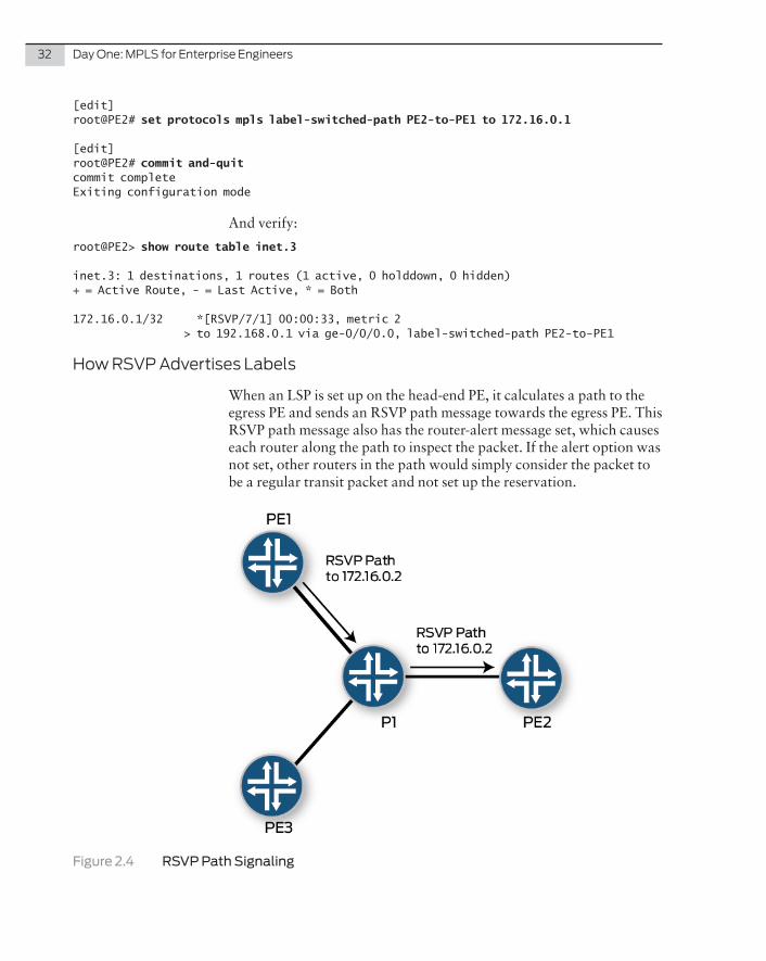
When an LSP is set up on the head-end PE, it calculates a path to the egress PE and sends an RSVP path message towards the egress PE. This RSVP path message also has the router-alert message set, which causes each router along the path to inspect the packet. If the alert option was not set, other routers in the path would simply consider the packet to be a regular transit packet and not set up the reservation.
Figure 2.4 RSVP Path Signaling
Chapter 2: Label Distribution Protocols 33
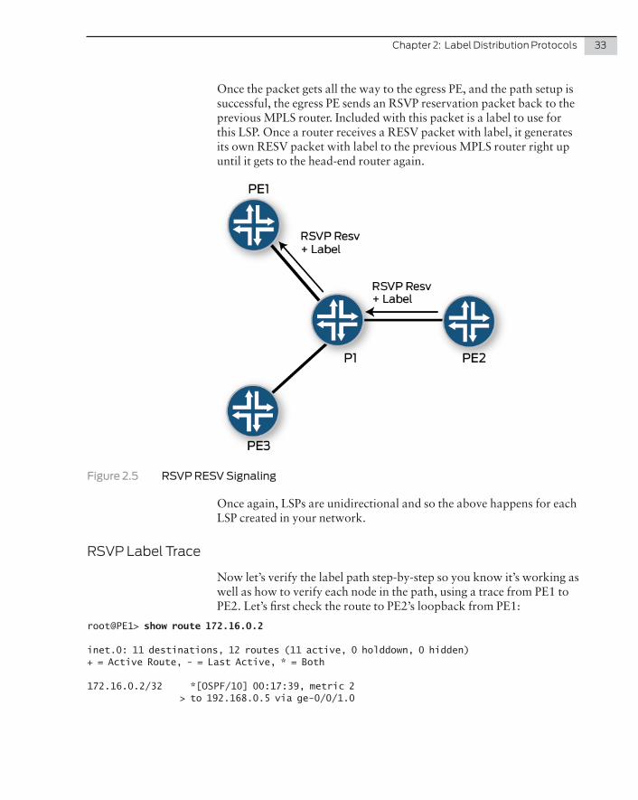
Once the packet gets all the way to the egress PE, and the path setup is successful, the egress PE sends an RSVP reservation packet back to the previous MPLS router. Included with this packet is a label to use for this LSP. Once a router receives a RESV packet with label, it generates its own RESV packet with label to the previous MPLS router right up until it gets to the head-end router again.
Figure 2.5 RSVP RESV Signaling
Once again, LSPs are unidirectional and so the above happens for each LSP created in your network.
RSVP Label Trace
Now let’s verify the label path step-by-step so you know it’s working as well as how to verify each node in the path, using a trace from PE1 to PE2. Let’s first check the route to PE2’s loopback from PE1:
root@PE1> show route 172.16.0.2
inet.0: 11 destinations, 12 routes (11 active, 0 holddown, 0 hidden)+ = Active Route, - = Last Active, * = Both
172.16.0.2/32 *[OSPF/10] 00:17:39, metric 2 > to 192.168.0.5 via ge-0/0/1.0
34 Day One: MPLS for Enterprise Engineers
inet.3: 1 destinations, 1 routes (1 active, 0 holddown, 0 hidden)+ = Active Route, - = Last Active, * = Both
172.16.0.2/32 *[RSVP/7/1] 00:17:31, metric 2 > to 192.168.0.5 via ge-0/0/1.0, label-switched-path PE1-to-PE2
PE1 has a regular OSPF route as well as a labeled next-hop in inet.3. The route in inet.3 shows that when PE1 sends a labeled packet to PE2, it sends it through label-switched-path PE1-to-PE2.
Unlike LDP, Junos won’t show you the label imposed in this output. You’ll need to dig a bit deeper to get that information:
root@PE1> show route protocol rsvp 172.16.0.2 extensive
inet.0: 11 destinations, 12 routes (11 active, 0 holddown, 0 hidden)
inet.3: 1 destinations, 1 routes (1 active, 0 holddown, 0 hidden)172.16.0.2/32 (1 entry, 1 announced) State: <FlashAll> *RSVP Preference: 7/1 Next hop type: Router Address: 0x958451c Next-hop reference count: 4 Next hop: 192.168.0.5 via ge-0/0/1.0, selected Label-switched-path PE1-to-PE2 Label operation: Push 299776 Label TTL action: prop-ttl Load balance label: Label 299776: None; Session Id: 0x0 State: <Active Int> Age: 21:43 Metric: 2 Validation State: unverified Task: RSVP Announcement bits (1): 0-Resolve tree 1 AS path: I
The important part here is the Label Operation: Push 299776.
When PE1 sends a labeled packet to PE2, it imposes the label 299776 onto the frame, and sends out ge-0/0/1.0 towards P.
The P router is now the penultimate router, meaning it should pop the above transport label and send it towards PE2. Let’s verify:
root@P1> show route table mpls.0 label 299776
mpls.0: 6 destinations, 6 routes (6 active, 0 holddown, 0 hidden)+ = Active Route, - = Last Active, * = Both
299776 *[RSVP/7/1] 00:24:27, metric 1 > to 192.168.0.0 via ge-0/0/2.0, label-switched-path PE1-to-PE2299776(S=0) *[RSVP/7/1] 00:24:27, metric 1 > to 192.168.0.0 via ge-0/0/2.0, label-switched-path PE1-to-PE2
Chapter 2: Label Distribution Protocols 35
Again, unlike LDP, Junos won’t show exactly what the label operation will be in this output:
root@P1> show route table mpls.0 label 299776 extensive | match operation Label operation: Pop Label operation: Pop
Only by checking the extensive command, and filtering on the label operation, can you see that the P router pops the transport RSVP label off the packet and sends it on its way out ge-0/0/2.0 towards PE2.
You can traceroute over the LSP to see the label’s values:
root@PE1> traceroute mpls rsvp PE1-to-PE2 Probe options: retries 3, exp 7
ttl Label Protocol Address Previous Hop Probe Status 1 299776 RSVP-TE 192.168.0.5 (null) Unhelpful 2 172.16.0.2 192.168.0.5 Egress
Of course in a larger network the transport label is swapped many more times until the PHP router.
RSVP Authentication
RSVP authentication is done on a per-interface basis, unlike LDP, which is per-session. When authentication is enabled, Junos authenti-cates both the RSVP hello and authentication messages on the config-ured interface.
In Junos, RSVP (currently) only uses MD5 authentication and it is configured like so:
root@PE1> configureEntering configuration mode
[edit]root@PE1# edit protocols rsvp
[edit protocols rsvp]root@PE1# set interface ge-0/0/1.0 authentication-key mplsEE
[edit protocols rsvp]root@PE1# top show | compare[edit protocols rsvp interface ge-0/0/1.0]+ authentication-key "$9$ROVhrvM87bs4X7w24aDj"; ## SECRET-DATA
[edit protocols rsvp]root@PE1# commit and-quitcommit completeExiting configuration mode
36 Day One: MPLS for Enterprise Engineers
You need to match this on P’s interface to PE1:
root@P1> show configuration protocols rsvpinterface all;interface ge-0/0/0.0 { authentication-key "$9$1QLRSeKMXdb28XVs24GU"; ## SECRET-DATA
}
Now, verifying that authentication is working is a little cryptic:
root@PE1> show rsvp interface ge-0/0/1.0 extensivege-0/0/1.0 Index 330, State Ena/Up Authentication, NoAggregate, NoReliable, NoLinkProtection
Of course the ultimate test is to verify that the LSP is up and stays up.
RSVP Optimization
RSVP prefers stability, so while the LSP is currently following the IGP, that LSP will not move to a newer, lower-cost, path unless you tell it to do so.
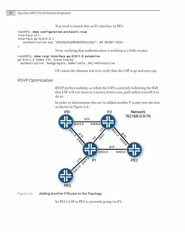
In order to demonstrate this we’ve added another P router into the mix as shown in Figure 2.6.
Figure 2.6 Adding Another P Router to the Topology
So PE1’s LSP to PE2 is currently going via P1:
Chapter 2: Label Distribution Protocols 37
root@PE1> show mpls lsp name PE1-to-PE2 extensive | find Computed Computed ERO (S [L] denotes strict [loose] hops): (CSPF metric: 2) 192.168.0.5 S 192.168.0.0 S Received RRO (ProtectionFlag 1=Available 2=InUse 4=B/W 8=Node 10=SoftPreempt 20=Node-ID): 192.168.0.5 192.168.0.0
If you change the cost of PE1’s link to P1, the LSP will continue to run over the link because RSVP calculates an ERO (explicit-route object) and signals the path. The path stays the same until it’s told to recalcu-late. Recalculating the ERO is called re-optimization, and it can occur manually, automatically through configuration, or on the back of a fault along the path. Let’s explore.
Let’s change the cost of PE1’s interface first, and then check the LSP:
root@PE1> configureEntering configuration mode
root@PE1# set protocols ospf area 0 interface ge-0/0/1.0 metric 20000
[edit]root@PE1# commit and-quitcommit completeExiting configuration mode
The LSP path should remain unchanged:
root@PE1> show mpls lsp name PE1-to-PE2 extensive | find Computed Computed ERO (S [L] denotes strict [loose] hops): (CSPF metric: 2) 192.168.0.5 S 192.168.0.0 S Received RRO (ProtectionFlag 1=Available 2=InUse 4=B/W 8=Node 10=SoftPreempt 20=Node-ID): 192.168.0.5 192.168.0.0
You need to manually inform Junos to recalculate the ERO:
root@PE1> clear mpls lsp optimize
root@PE1> show mpls lsp name PE1-to-PE2 extensive | find Computed Computed ERO (S [L] denotes strict [loose] hops): (CSPF metric: 2) 192.168.0.7 S 192.168.0.8 S Received RRO (ProtectionFlag 1=Available 2=InUse 4=B/W 8=Node 10=SoftPreempt 20=Node-ID): 192.168.0.7 192.168.0.8
You can see that the path has changed.
Junos can be configured to reoptimize on a timed basis and at each timed interval the ERO is recalculated. If the ERO is the same, or there is no benefit in moving, the LSP simply stays on the same path. If there is a better path then a new path is signaled. Let’s set the timer:
38 Day One: MPLS for Enterprise Engineers
root@PE1# set protocols mpls optimize-timer 3600
root@PE1> show mpls lsp name PE1-to-PE2 extensive | match Reoptimization Reoptimization in 3553 second(s).
Fast Restoration
In order to see the benefits of fast restoration, you first need to see the drawbacks of a network without it.
Let’s move the LSP from PE1 to PE2 back to normal so it’s going through PE1-P-PE2. If the link between P1 and PE2 goes down, then that information needs to be signaled to the head-end router to recalculate the path. Once a new path is recalculated, it needs to be signaled. Once the path is finally up, traffic can move onto the path.
All that can take time. Just getting that information to the head-end router can take a few hundred milliseconds, in a large network.
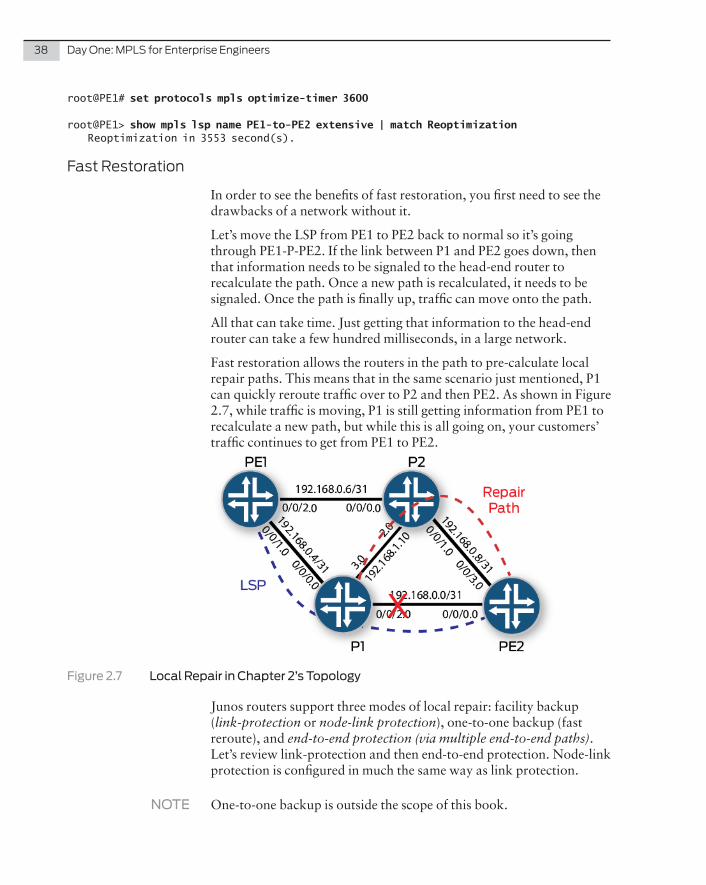
Fast restoration allows the routers in the path to pre-calculate local repair paths. This means that in the same scenario just mentioned, P1 can quickly reroute traffic over to P2 and then PE2. As shown in Figure 2.7, while traffic is moving, P1 is still getting information from PE1 to recalculate a new path, but while this is all going on, your customers’ traffic continues to get from PE1 to PE2.
Figure 2.7 Local Repair in Chapter 2’s Topology
Junos routers support three modes of local repair: facility backup (link-protection or node-link protection), one-to-one backup (fast reroute), and end-to-end protection (via multiple end-to-end paths). Let’s review link-protection and then end-to-end protection. Node-link protection is configured in much the same way as link protection.
NOTE One-to-one backup is outside the scope of this book.
Chapter 2: Label Distribution Protocols 39
Fast Restoration Link-Protection Configuration
Link protection needs to be enabled on the link you want to protect. It’s an RSVP feature and so it’s configured under the RSVP stanza:
root@P1# set protocols rsvp interface ge-0/0/2.0 link-protection
Now you need to configure the head-end tunnel to ensure that the LSP itself has link-protection signaled so that it uses it where available:
root@PE1# show | compare[edit protocols mpls label-switched-path PE1-to-PE2]
+ link-protection;
Fast Restoration Verification
Let’s first check to see that the head-end has signaled correctly:
root@PE1> show mpls lsp extensive | match protection Link protection desired Received RRO (ProtectionFlag 1=Available 2=InUse 4=B/W 8=Node 10=SoftPreempt 20=Node-ID):
Now, check on the router that is the repair point, in this case P1:
root@P1> show mpls lsp transit name PE1-to-PE2 extensive | match Link Link protection desired Type: Link protected LSP, using Bypass->192.168.0.0 1 Jan 3 06:07:24 Link protection up, using Bypass->192.168.0.0
And you can see that P1 has the protection path correctly signaled.
If you look at the labeled route to PE2, you can see that PE1 imposes the label value of 299872:
root@PE1> show route protocol rsvp 172.16.0.2 extensive | match label Label-switched-path PE1-to-PE2 Label operation: Push 299872
But looking at the label from P1’s perspective, this label path has two possibilities: the first is the regular path, while the second is the bypass path used when the original link is down:
root@P1> show route table mpls.0 label 299872
mpls.0: 6 destinations, 6 routes (6 active, 0 holddown, 0 hidden)+ = Active Route, - = Last Active, * = Both
299872 *[RSVP/7/1] 02:41:47, metric 1 > to 192.168.0.0 via ge-0/0/2.0, label-switched-path PE1-to-PE2 to 192.168.0.11 via ge-0/0/3.0, label-switched-path Bypass->192.168.0.0
40 Day One: MPLS for Enterprise Engineers
NOTE While there is an alternative in the RIB, it still needs to be programmed into the FIB in the event of a link-failure. This can be sped up by informing Junos to have the backup-path preprogrammed into the FIB.
If you check the forwarding table you should see only the original hop:
root@P1> show route forwarding-table label 299872Routing table: default.mplsMPLS:Destination Type RtRef Next hop Type Index NhRef Netif299872 user 0 192.168.0.0 Pop 559 2 ge-0/0/2.0
So let’s configure Junos to install the backup path into the FIB. It’s straightforward:
root@P1# show | compare[edit]+ routing-options {+ forwarding-table {+ export BOTH;+ }+ }+ policy-options {+ policy-statement BOTH {+ then {+ load-balance per-packet;+ }+ }+ }
And verify the forwarding table state:
root@P1> show route forwarding-table label 299872Routing table: default.mplsMPLS:Destination Type RtRef Next hop Type Index NhRef Netif299872 user 0 ulst 1048575 2 192.168.0.0 Pop 559 2 ge-0/0/2.0 192.168.0.11 Swap 299824 564 2 ge-0/0/3.0
NOTE Remember that LSPs are unidirectional. Therefore putting in the backup path is only for the protection of the LSP from PE1 to PE2. In the real world of your new or pending Service Provider job, you’d want to have the same protection from PE2 back to PE1. Therefore the same configuration will need to be done in the reverse path.
NOTE You can use the show route forwarding-table xxx extensive command to show the next-hop weight. The lower weight is the entry that would be used for actual forwarding.
Chapter 2: Label Distribution Protocols 41
RSVP Explicit Path
Up until this point, you’ve simply used the IGP’s TE extensions to calculate the ERO path. RSVP also gives you the option to hard-code a path to go any way you’d like it to go, which might allow you to fully use all of your core links more effectively.
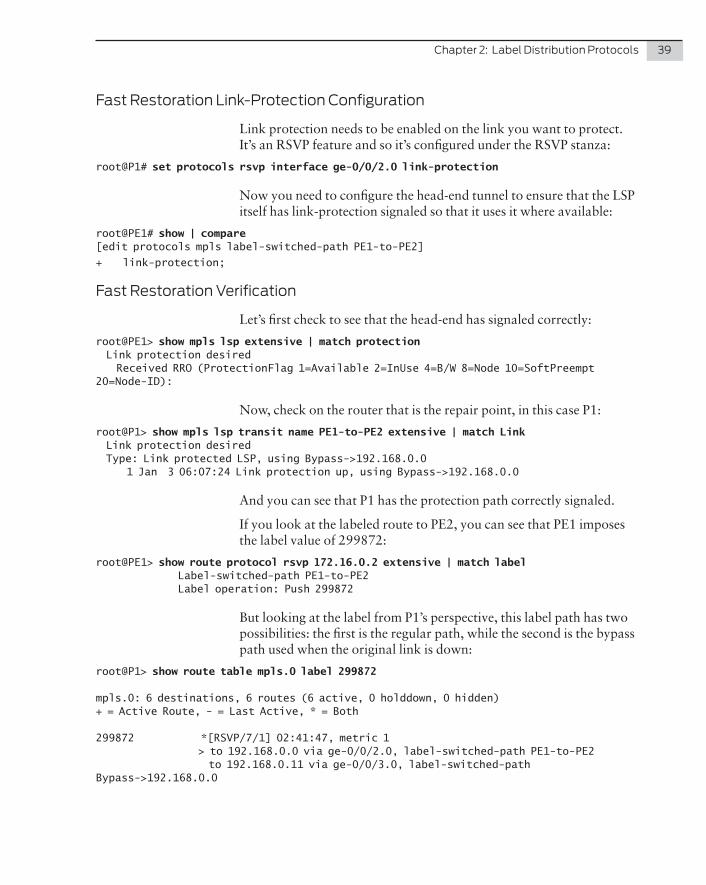
For the following tutorial, let’s configure two LSPs from PE1 to PE2 as shown in Figure 2.8. Each LSP will be going over a different path:
Figure 2.8 Configuring RSVP Explicit Path
Configuration
First you need to configure a path, and that path can contain both strict hops. Essentially a strict hop means that the next-hop needs to be directly connected to the next router in the path. Loose means you can follow the IGP to the next IP address in the path and it can be multiple hops away. As this test network is small, let’s simply inform PE1 to have a strict path to either P1’s or P2’s directly connected interface address, like so:
root@PE1> show configuration protocols mpls path VIA-P1192.168.0.5 strict;
root@PE1> show configuration protocols mpls path VIA-P2192.168.0.7 strict;
Now create two LSPs, with each referring to the newly created paths:
root@PE1> show configuration protocols mplslabel-switched-path PE1-to-PE2-1 { to 172.16.0.2; primary VIA-P1;}
42 Day One: MPLS for Enterprise Engineers
label-switched-path PE1-to-PE2-2 { to 172.16.0.2; primary VIA-P2;}
Now let’s verify. First check that both LSPs are up:
root@PE1> show mpls lspIngress LSP: 2 sessionsTo From State Rt P ActivePath LSPname172.16.0.2 172.16.0.1 Up 0 * VIA-P1 PE1-to-PE2-1172.16.0.2 172.16.0.1 Up 0 * VIA-P2 PE1-to-PE2-2
They are up. Now let’s see if the first LSP goes out via ge-0/0/1.0 and the second via ge-0/0/0.2:
root@PE1> show route protocol rsvp
inet.3: 1 destinations, 1 routes (1 active, 0 holddown, 0 hidden)+ = Active Route, - = Last Active, * = Both
172.16.0.2/32 *[RSVP/7/1] 00:07:21, metric 2 > to 192.168.0.5 via ge-0/0/1.0, label-switched-path PE1-to-PE2-1 to 192.168.0.7 via ge-0/0/2.0, label-switched-path PE1-to-PE2-2
And it’s live! Finally, let’s verify that both P routers shows a single unidirectional LSP going towards PE2:
root@P1> show mpls lsp transitTransit LSP: 1 sessionsTo From State Rt Style Labelin Labelout LSPname172.16.0.2 172.16.0.1 Up 0 1 FF 299904 3 PE1-to-PE2-1Total 1 displayed, Up 1, Down 0
root@P2> show mpls lsp transitTransit LSP: 1 sessionsTo From State Rt Style Labelin Labelout LSPname172.16.0.2 172.16.0.1 Up 0 1 FF 299856 3 PE1-to-PE2-2Total 1 displayed, Up 1, Down 0
Summary
This has been the quickest review of configuring MPLS in the core ever written, but it should be enough to create a foundation for understand-ing all of those longer texts and tutorials out there. MPLS can be very complicated in large networks, so allow yourself time to research, read, and get in the lab. Next up? Configuring a Layer 3 VPN.
43
Now that you understand why and how MPLS is configured in the core, it’s time to start configuring customers to use the service – you are a provider now, remember?
With a Level 3 VPN service, the PE routers are actively taking part in the routing between customer sites. That is, customer routers (CE routers) are running a routing protocol with the PE router at each site. CE routers will forward traffic to PE routers, which will do a Layer 3 lookup to determine which PE or CE to send that traffic to.
The routing protocol used between the CE and PE is generally BGP, but OSPF and static routing is also fairly common. This chapter covers both BGP and OSPF.
For both the OSPF and BGP section let’s add a few CE routers into the topology, as shown in Figure 3.1.
Chapter 3
Layer 3 VPN
44 Day One: MPLS for Enterprise Engineers
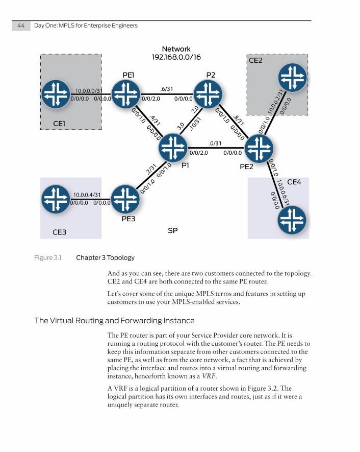
Figure 3.1 Chapter 3 Topology
And as you can see, there are two customers connected to the topology. CE2 and CE4 are both connected to the same PE router.
Let’s cover some of the unique MPLS terms and features in setting up customers to use your MPLS-enabled services.
The Virtual Routing and Forwarding Instance
The PE router is part of your Service Provider core network. It is running a routing protocol with the customer’s router. The PE needs to keep this information separate from other customers connected to the same PE, as well as from the core network, a fact that is achieved by placing the interface and routes into a virtual routing and forwarding instance, henceforth known as a VRF.
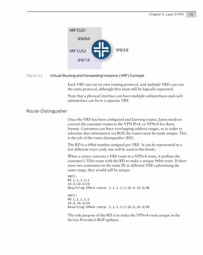
A VRF is a logical partition of a router shown in Figure 3.2. The logical partition has its own interfaces and routes, just as if it were a uniquely separate router.
Chapter 3: Layer 3 VPN 45
Figure 3.2 Virtual Routing and Forwarding Instance (VRF) Concept
Each VRF can run its own routing protocol, and multiple VRFs can run the same protocol, although they must still be logically separated.
Note that a physical interface can have multiple subinterfaces and each subinterface can be in a separate VRF.
Route-Distinguisher
Once the VRF has been configured and learning routes, Junos needs to convert the customer routes to the VPN IPv4, or VPNv4 for short, format. Customers can have overlapping address ranges, so in order to advertise that information via BGP, the routes must be made unique. This is the job of the route-distinguisher (RD).
The RD is a 64bit number assigned per VRF. It can be represented in a few different ways (only one will be used in this book).
When a router converts a VRF route to a VPNv4 route, it prefixes the customer’s 32bit route with the RD to make a unique 96bit route. If there were two customers on the same PE in different VRFs advertising the same range, they would still be unique.
VRF1:RD 1.1.1.1:110.0.10.0/24Resulting VPNv4 route: 1.1.1.1:1:10.0.10.0/96
VRF2:RD 1.1.1.1:210.0.10.0/24Resulting VPNv4 route: 1.1.1.1:2:10.0.10.0/96
The sole purpose of the RD is to make the VPNv4 route unique in the Service Provider’s BGP updates.
46 Day One: MPLS for Enterprise Engineers
Route-Target
The route-target (RT) is an extended community value attached to the VPNv4 route. Each configured PE exports route-targets, which are attached to routes going from the VRF to VPNv4, and imports route-targets. Any incoming VPNv4 route that has a matching RT to the current import on the local PE, is converted from VPNv4 and placed into the VRF on the local PE. Note that multiple route-targets can be exported and imported.
If a customer purchases an L3VPN service from the Service Provider, it would make sense that the customer would want all of its sites to have full connectivity to all sites. In this case, a single RT would be config-ured inbound and outbound on all PEs in the customer’s VRF.
This is not always the case, however. It may be that the customer wants a hub-and-spoke network, or may want to connect to another custom-er’s network through the Service Provider’s MPLS core. In this case, you may want different route-targets imported and exported.
At the end of it all, the route-target is an extended community that tells PE routers which VRF the update belongs to.
Creating the VRF
VRF’s are defined in the routing-instance stanza. The CE-facing interfaces are included in the VRF config, as well as the RD and RT values. The IP addressing for the interface is still done under the interface itself:
root@PE1> show configuration routing-instancesCUS1 { instance-type vrf; interface ge-0/0/0.0; route-distinguisher 172.16.0.1:1; vrf-target target:64496:1; vrf-table-label;}root@PE1> show configuration interfaces ge-0/0/0unit 0 { family inet { address 10.0.0.1/31; }}
When a new VRF is created, Junos creates a new routing table for that VRF. Having assigned an interface with an IP address into that VRF, that route should be inside the VRF:
Chapter 3: Layer 3 VPN 47
root@PE1> show route table CUS1
CUS1.inet.0: 2 destinations, 2 routes (2 active, 0 holddown, 0 hidden)+ = Active Route, - = Last Active, * = Both
10.0.0.0/31 *[Direct/0] 00:04:45 > via ge-0/0/0.010.0.0.1/32 *[Local/0] 00:04:45 Local via ge-0/0/0.0
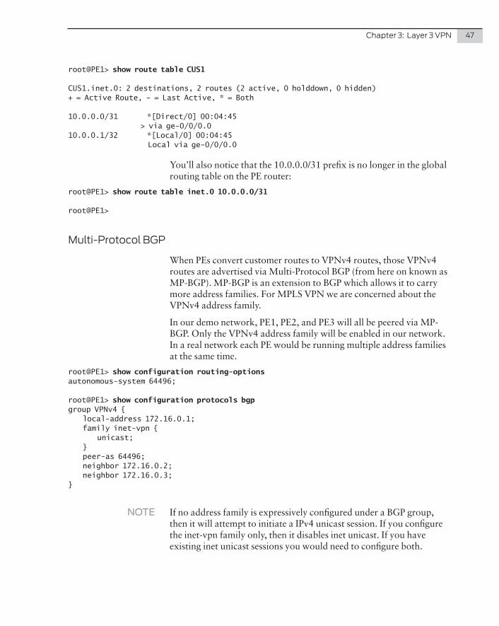
You’ll also notice that the 10.0.0.0/31 prefix is no longer in the global routing table on the PE router:
root@PE1> show route table inet.0 10.0.0.0/31
root@PE1>
Multi-Protocol BGP
When PEs convert customer routes to VPNv4 routes, those VPNv4 routes are advertised via Multi-Protocol BGP (from here on known as MP-BGP). MP-BGP is an extension to BGP which allows it to carry more address families. For MPLS VPN we are concerned about the VPNv4 address family.
In our demo network, PE1, PE2, and PE3 will all be peered via MP-BGP. Only the VPNv4 address family will be enabled in our network. In a real network each PE would be running multiple address families at the same time.
root@PE1> show configuration routing-optionsautonomous-system 64496;
root@PE1> show configuration protocols bgpgroup VPNv4 { local-address 172.16.0.1; family inet-vpn { unicast; } peer-as 64496; neighbor 172.16.0.2; neighbor 172.16.0.3;}
NOTE If no address family is expressively configured under a BGP group, then it will attempt to initiate a IPv4 unicast session. If you configure the inet-vpn family only, then it disables inet unicast. If you have existing inet unicast sessions you would need to configure both.
48 Day One: MPLS for Enterprise Engineers
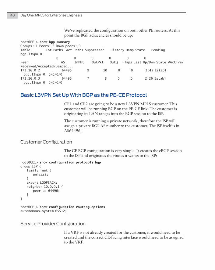
We’ve replicated the configuration on both other PE routers. At this point the BGP adjacencies should be up:
root@PE1> show bgp summaryGroups: 1 Peers: 2 Down peers: 0Table Tot Paths Act Paths Suppressed History Damp State Pendingbgp.l3vpn.0 0 0 0 0 0 0Peer AS InPkt OutPkt OutQ Flaps Last Up/Dwn State|#Active/Received/Accepted/Damped...172.16.0.2 64496 9 10 0 0 2:45 Establ bgp.l3vpn.0: 0/0/0/0172.16.0.3 64496 7 8 0 0 2:26 Establ bgp.l3vpn.0: 0/0/0/0
Basic L3VPN Set Up With BGP as the PE-CE Protocol
CE1 and CE2 are going to be a new L3VPN MPLS customer. This customer will be running BGP on the PE-CE link. The customer is originating its LAN ranges into the BGP session to the ISP.
The customer is running a private network; therefore the ISP will assign a private BGP AS number to the customer. The ISP itself is in AS64496.
Customer Configuration
The CE BGP configuration is very simple. It creates the eBGP session to the ISP and originates the routes it wants to the ISP:
root@CE1> show configuration protocols bgpgroup ISP { family inet { unicast; } export LOOPBACK; neighbor 10.0.0.1 { peer-as 64496; }}
root@CE1> show configuration routing-optionsautonomous-system 65512;
Service Provider Configuration
If a VRF is not already created for the customer, it would need to be created and the correct CE-facing interface would need to be assigned to the VRF.
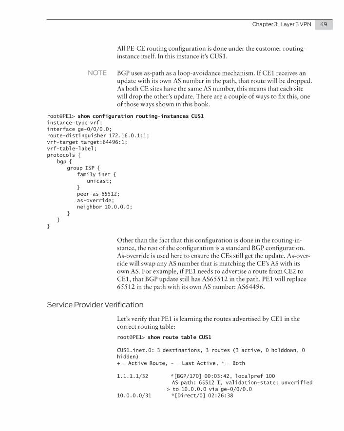
Chapter 3: Layer 3 VPN 49
All PE-CE routing configuration is done under the customer routing-instance itself. In this instance it’s CUS1.
NOTE BGP uses as-path as a loop-avoidance mechanism. If CE1 receives an update with its own AS number in the path, that route will be dropped. As both CE sites have the same AS number, this means that each site will drop the other’s update. There are a couple of ways to fix this, one of those ways shown in this book.
root@PE1> show configuration routing-instances CUS1instance-type vrf;interface ge-0/0/0.0;route-distinguisher 172.16.0.1:1;vrf-target target:64496:1;vrf-table-label;protocols { bgp { group ISP { family inet { unicast; } peer-as 65512; as-override; neighbor 10.0.0.0; } }}
Other than the fact that this configuration is done in the routing-in-stance, the rest of the configuration is a standard BGP configuration. As-override is used here to ensure the CEs still get the update. As-over-ride will swap any AS number that is matching the CE’s AS with its own AS. For example, if PE1 needs to advertise a route from CE2 to CE1, that BGP update still has AS65512 in the path. PE1 will replace 65512 in the path with its own AS number: AS64496.
Service Provider Verification
Let’s verify that PE1 is learning the routes advertised by CE1 in the correct routing table:
root@PE1> show route table CUS1
CUS1.inet.0: 3 destinations, 3 routes (3 active, 0 holddown, 0 hidden)+ = Active Route, - = Last Active, * = Both
1.1.1.1/32 *[BGP/170] 00:03:42, localpref 100 AS path: 65512 I, validation-state: unverified > to 10.0.0.0 via ge-0/0/0.010.0.0.0/31 *[Direct/0] 02:26:38
50 Day One: MPLS for Enterprise Engineers
> via ge-0/0/0.010.0.0.1/32 *[Local/0] 02:26:38 Local via ge-0/0/0.0
You can see that the route is in the VRF as a BGP route. Junos will automatically convert customer BGP routes to VPNv4 routes. These routes will be advertised over MP-BGP to PE2. If PE2 has an import-target that matches the community in the route, that route is placed into the local VRF. Let’s confirm this:
root@PE2> show route table bgp.l3vpn.0
bgp.l3vpn.0: 2 destinations, 2 routes (2 active, 0 holddown, 0 hidden)+ = Active Route, - = Last Active, * = Both
172.16.0.1:1:1.1.1.1/32 *[BGP/170] 00:29:43, localpref 100, from 172.16.0.1 AS path: 65512 I, validation-state: unverified > to 192.168.0.9 via ge-0/0/3.0, Push 299792, Push 299856(top)172.16.0.1:1:10.0.0.0/31 *[BGP/170] 00:29:42, localpref 100, from 172.16.0.1 AS path: I, validation-state: unverified > to 192.168.0.9 via ge-0/0/3.0, Push 299792, Push 299856(top)
The bgp.l3vpn.0 table contains all the MP-BGP VPNv4 NLRI re-ceived. If you check the 1.1.1.1 route in detail you’ll see the route-target inside the update:
root@PE2> show route table bgp.l3vpn.0 detail
bgp.l3vpn.0: 2 destinations, 2 routes (2 active, 0 holddown, 0 hidden)172.16.0.1:1:1.1.1.1/32 (1 entry, 0 announced) *BGP Preference: 170/-101 Route Distinguisher: 172.16.0.1:1 Next hop type: Indirect Address: 0x94ece50 Next-hop reference count: 6 Source: 172.16.0.1 Next hop type: Router, Next hop index: 547 Next hop: 192.168.0.9 via ge-0/0/3.0, selected Label operation: Push 299792, Push 299856(top) Label TTL action: prop-ttl, prop-ttl(top) Load balance label: Label 299792: None; Label 299856: None; Session Id: 0x2 Protocol next hop: 172.16.0.1 Label operation: Push 299792 Label TTL action: prop-ttl Load balance label: Label 299792: None; Indirect next hop: 0x96d0000 1048574 INH Session ID: 0x5 State: <Active Int Ext ProtectionPath ProtectionCand> Local AS: 64496 Peer AS: 64496 Age: 31:38 Metric2: 1 Validation State: unverified Task: BGP_64496.172.16.0.1
Chapter 3: Layer 3 VPN 51
AS path: 65512 I Communities: target:64496:1 Import Accepted VPN Label: 299792 Localpref: 100 Router ID: 10.255.255.171 Secondary Tables: CUS1.inet.0
As the community matches a current import value in the VRF on PE2, that route is inserted into the customer VRF:
root@PE2> show route table CUS1 1.1.1.1
CUS1.inet.0: 5 destinations, 5 routes (5 active, 0 holddown, 0 hidden)+ = Active Route, - = Last Active, * = Both
1.1.1.1/32 *[BGP/170] 02:36:12, localpref 100, from 172.16.0.1 AS path: 65512 I, validation-state: unverified > to 192.168.0.9 via ge-0/0/3.0, Push 299792, Push 299856(top)
As the route is a BGP route, and the ISP is running BGP with the customer, that route will be advertised to the customer without having to redistribute first. CE2 would therefore have the route learned via BGP:
root@CE2> show route 1.1.1.1
inet.0: 7 destinations, 8 routes (7 active, 0 holddown, 1 hidden)+ = Active Route, - = Last Active, * = Both
1.1.1.1/32 *[BGP/170] 02:37:33, localpref 100 AS path: 64496 64496 I, validation-state: unverified > to 10.0.0.3 via ge-0/0/0.0
As expected, the as-path is 64496 64496. Without as-override on the PE, the path would’ve been 64496 64512, and that would have been rejected because it’s the same AS number as the local AS on the CE router.
From the CE’s perspective, the route itself is a normal IPv4 BGP route. There is no MPLS running on any CE kit.
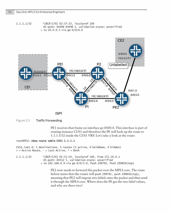
Customer Traffic Forwarding
CE2 has a route to CE1’s loopback address and it’s a regular IPv4 route as shown in Figure 3.3. This means that CE1 is sending a standard Ethernet frame to PE1. Let’s see:
root@CE2> show route 1.1.1.1
inet.0: 7 destinations, 8 routes (7 active, 0 holddown, 1 hidden)+ = Active Route, - = Last Active, * = Both
52 Day One: MPLS for Enterprise Engineers
1.1.1.1/32 *[BGP/170] 02:37:33, localpref 100 AS path: 64496 64496 I, validation-state: unverified > to 10.0.0.3 via ge-0/0/0.0
Figure 3.3 Traffic Forwarding
PE1 receives that frame on interface ge-0/0/0.0. This interface is part of routing-instance CUS1 and therefore the PE will look up the route to 1.1.1.1/32 inside the CUS1 VRF. Let’s take a look at the route:
root@PE2> show route table CUS1 1.1.1.1
CUS1.inet.0: 5 destinations, 5 routes (5 active, 0 holddown, 0 hidden)+ = Active Route, - = Last Active, * = Both
1.1.1.1/32 *[BGP/170] 02:51:24, localpref 100, from 172.16.0.1 AS path: 64512 I, validation-state: unverified > to 192.168.0.9 via ge-0/0/3.0, Push 299792, Push 299856(top)
PE2 now needs to forward this packet over the MPLS core. The route before states that the router will push 299792, push 299856(top), meaning that PE2 will impose two labels onto the packet and then send it through the MPLS core. Where does the PE get the two label values, and why are there two?
Chapter 3: Layer 3 VPN 53
The first thing the PE looks at is the next-hop of the route:
root@PE2> show route table CUS1 1.1.1.1 detail | match "next hop" Next hop type: Indirect Next hop type: Router, Next hop index: 547 Next hop: 192.168.0.9 via ge-0/0/3.0, selected Protocol next hop: 172.16.0.1 Indirect next hop: 0x96d0000 1048574 INH Session ID: 0x5
The protocol-next-hop is the loopback address of PE1. PE2 will check to see if it has a labeled route to PE1:
root@PE2> show route table inet.3 172.16.0.1
inet.3: 3 destinations, 3 routes (3 active, 0 holddown, 0 hidden)+ = Active Route, - = Last Active, * = Both
172.16.0.1/32 *[LDP/9] 02:59:31, metric 1 > to 192.168.0.9 via ge-0/0/3.0, Push 299856
The topmost label is the transport label. Notice that the top label imposed is the same label that’s used to label-switch traffic from PE2 to PE1.
The second label, sitting beneath the transport label, is the VPN label. PE2 learns this through the original BGP update from PE1 for this prefix:
root@PE2> show route receive-protocol bgp 172.16.0.1 1.1.1.1 detail
CUS1.inet.0: 5 destinations, 5 routes (5 active, 0 holddown, 0 hidden)* 1.1.1.1/32 (1 entry, 1 announced) Import Accepted Route Distinguisher: 172.16.0.1:1 VPN Label: 299792 Nexthop: 172.16.0.1 Localpref: 100 AS path: 65512 I Communities: target:64496:1
Therefore the VPN label is advertised through BGP, but the transport label is still signaled via LDP or RSVP. A VPN label never changes as the packet is switched through the core – only the transport label changes. On the penultimate router, the transport label will still be popped, but the VPN label will only be stripped on the final PE.
Why is the VPN label required? Without it, if PE1 receives a packet from the core, the packet is simply a standard IP packet. It has a source address and a destination address. The PE would not be able to determine which VRF that packet is part of, as this packet is coming inbound via the Service Provider core.
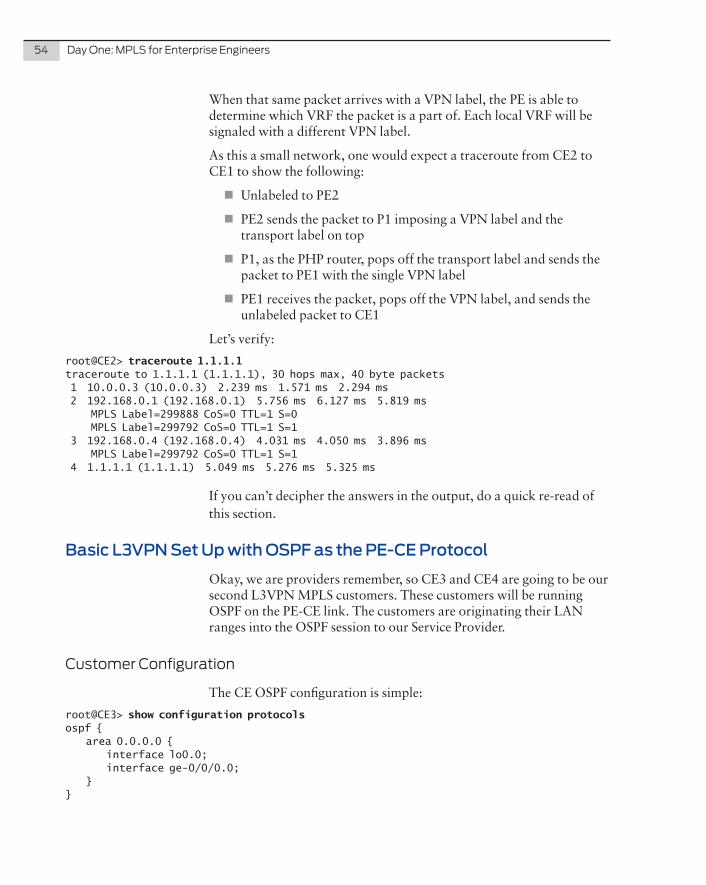
54 Day One: MPLS for Enterprise Engineers
When that same packet arrives with a VPN label, the PE is able to determine which VRF the packet is a part of. Each local VRF will be signaled with a different VPN label.
As this a small network, one would expect a traceroute from CE2 to CE1 to show the following:
� Unlabeled to PE2
� PE2 sends the packet to P1 imposing a VPN label and the transport label on top
� P1, as the PHP router, pops off the transport label and sends the packet to PE1 with the single VPN label
� PE1 receives the packet, pops off the VPN label, and sends the unlabeled packet to CE1
Let’s verify:
root@CE2> traceroute 1.1.1.1traceroute to 1.1.1.1 (1.1.1.1), 30 hops max, 40 byte packets 1 10.0.0.3 (10.0.0.3) 2.239 ms 1.571 ms 2.294 ms 2 192.168.0.1 (192.168.0.1) 5.756 ms 6.127 ms 5.819 ms MPLS Label=299888 CoS=0 TTL=1 S=0 MPLS Label=299792 CoS=0 TTL=1 S=1 3 192.168.0.4 (192.168.0.4) 4.031 ms 4.050 ms 3.896 ms MPLS Label=299792 CoS=0 TTL=1 S=1 4 1.1.1.1 (1.1.1.1) 5.049 ms 5.276 ms 5.325 ms
If you can’t decipher the answers in the output, do a quick re-read of this section.
Basic L3VPN Set Up with OSPF as the PE-CE Protocol
Okay, we are providers remember, so CE3 and CE4 are going to be our second L3VPN MPLS customers. These customers will be running OSPF on the PE-CE link. The customers are originating their LAN ranges into the OSPF session to our Service Provider.
Customer Configuration
The CE OSPF configuration is simple:
root@CE3> show configuration protocolsospf { area 0.0.0.0 { interface lo0.0; interface ge-0/0/0.0; }}
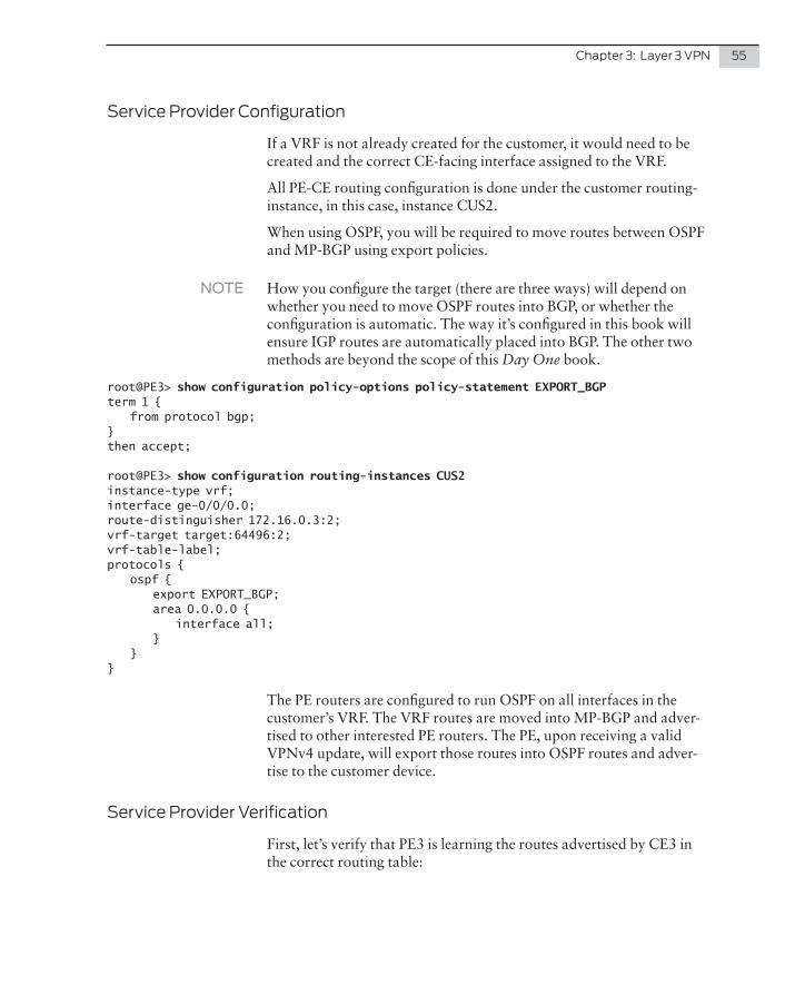
Chapter 3: Layer 3 VPN 55
Service Provider Configuration
If a VRF is not already created for the customer, it would need to be created and the correct CE-facing interface assigned to the VRF.
All PE-CE routing configuration is done under the customer routing-instance, in this case, instance CUS2.
When using OSPF, you will be required to move routes between OSPF and MP-BGP using export policies.
NOTE How you configure the target (there are three ways) will depend on whether you need to move OSPF routes into BGP, or whether the configuration is automatic. The way it’s configured in this book will ensure IGP routes are automatically placed into BGP. The other two methods are beyond the scope of this Day One book.
root@PE3> show configuration policy-options policy-statement EXPORT_BGPterm 1 { from protocol bgp;}then accept;
root@PE3> show configuration routing-instances CUS2instance-type vrf;interface ge-0/0/0.0;route-distinguisher 172.16.0.3:2;vrf-target target:64496:2;vrf-table-label;protocols { ospf { export EXPORT_BGP; area 0.0.0.0 { interface all; } }}
The PE routers are configured to run OSPF on all interfaces in the customer’s VRF. The VRF routes are moved into MP-BGP and adver-tised to other interested PE routers. The PE, upon receiving a valid VPNv4 update, will export those routes into OSPF routes and adver-tise to the customer device.
Service Provider Verification
First, let’s verify that PE3 is learning the routes advertised by CE3 in the correct routing table:
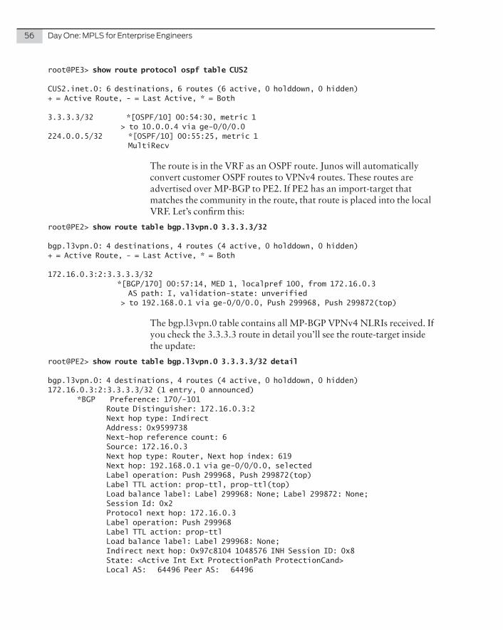
56 Day One: MPLS for Enterprise Engineers
root@PE3> show route protocol ospf table CUS2
CUS2.inet.0: 6 destinations, 6 routes (6 active, 0 holddown, 0 hidden)+ = Active Route, - = Last Active, * = Both
3.3.3.3/32 *[OSPF/10] 00:54:30, metric 1 > to 10.0.0.4 via ge-0/0/0.0224.0.0.5/32 *[OSPF/10] 00:55:25, metric 1 MultiRecv
The route is in the VRF as an OSPF route. Junos will automatically convert customer OSPF routes to VPNv4 routes. These routes are advertised over MP-BGP to PE2. If PE2 has an import-target that matches the community in the route, that route is placed into the local VRF. Let’s confirm this:
root@PE2> show route table bgp.l3vpn.0 3.3.3.3/32
bgp.l3vpn.0: 4 destinations, 4 routes (4 active, 0 holddown, 0 hidden)+ = Active Route, - = Last Active, * = Both
172.16.0.3:2:3.3.3.3/32 *[BGP/170] 00:57:14, MED 1, localpref 100, from 172.16.0.3 AS path: I, validation-state: unverified > to 192.168.0.1 via ge-0/0/0.0, Push 299968, Push 299872(top)
The bgp.l3vpn.0 table contains all MP-BGP VPNv4 NLRIs received. If you check the 3.3.3.3 route in detail you’ll see the route-target inside the update:
root@PE2> show route table bgp.l3vpn.0 3.3.3.3/32 detail
bgp.l3vpn.0: 4 destinations, 4 routes (4 active, 0 holddown, 0 hidden)172.16.0.3:2:3.3.3.3/32 (1 entry, 0 announced) *BGP Preference: 170/-101 Route Distinguisher: 172.16.0.3:2 Next hop type: Indirect Address: 0x9599738 Next-hop reference count: 6 Source: 172.16.0.3 Next hop type: Router, Next hop index: 619 Next hop: 192.168.0.1 via ge-0/0/0.0, selected Label operation: Push 299968, Push 299872(top) Label TTL action: prop-ttl, prop-ttl(top) Load balance label: Label 299968: None; Label 299872: None; Session Id: 0x2 Protocol next hop: 172.16.0.3 Label operation: Push 299968 Label TTL action: prop-ttl Load balance label: Label 299968: None; Indirect next hop: 0x97c8104 1048576 INH Session ID: 0x8 State: <Active Int Ext ProtectionPath ProtectionCand> Local AS: 64496 Peer AS: 64496
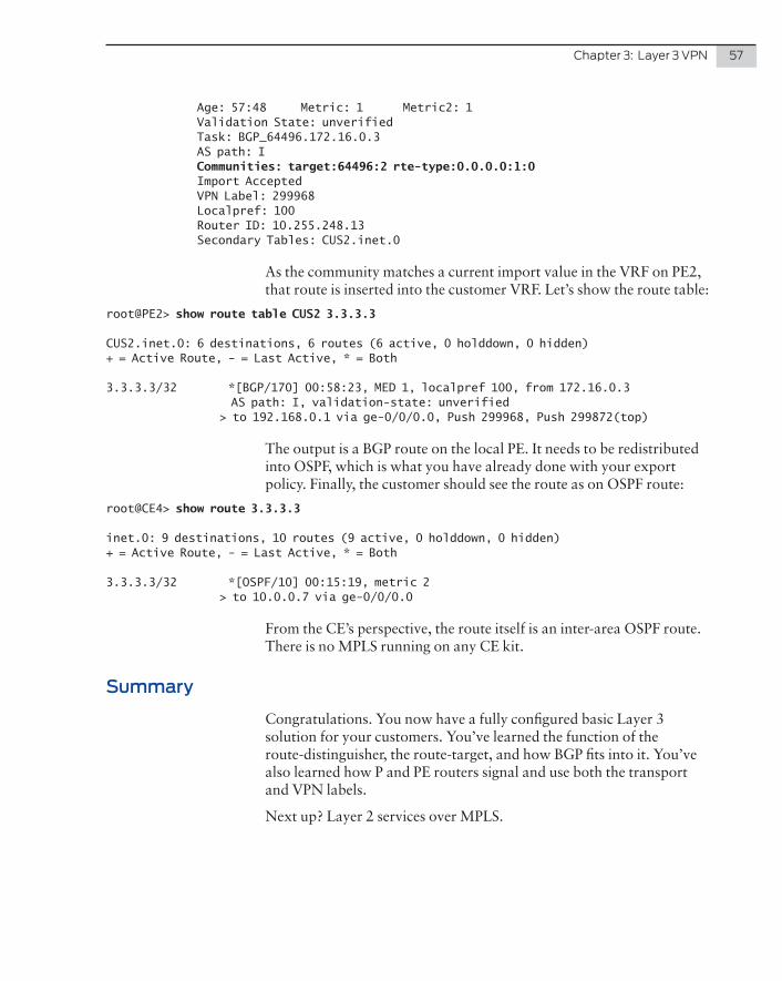
Chapter 3: Layer 3 VPN 57
Age: 57:48 Metric: 1 Metric2: 1 Validation State: unverified Task: BGP_64496.172.16.0.3 AS path: I Communities: target:64496:2 rte-type:0.0.0.0:1:0 Import Accepted VPN Label: 299968 Localpref: 100 Router ID: 10.255.248.13 Secondary Tables: CUS2.inet.0
As the community matches a current import value in the VRF on PE2, that route is inserted into the customer VRF. Let’s show the route table:
root@PE2> show route table CUS2 3.3.3.3
CUS2.inet.0: 6 destinations, 6 routes (6 active, 0 holddown, 0 hidden)+ = Active Route, - = Last Active, * = Both
3.3.3.3/32 *[BGP/170] 00:58:23, MED 1, localpref 100, from 172.16.0.3 AS path: I, validation-state: unverified > to 192.168.0.1 via ge-0/0/0.0, Push 299968, Push 299872(top)
The output is a BGP route on the local PE. It needs to be redistributed into OSPF, which is what you have already done with your export policy. Finally, the customer should see the route as on OSPF route:
root@CE4> show route 3.3.3.3
inet.0: 9 destinations, 10 routes (9 active, 0 holddown, 0 hidden)+ = Active Route, - = Last Active, * = Both
3.3.3.3/32 *[OSPF/10] 00:15:19, metric 2 > to 10.0.0.7 via ge-0/0/0.0
From the CE’s perspective, the route itself is an inter-area OSPF route. There is no MPLS running on any CE kit.
Summary
Congratulations. You now have a fully configured basic Layer 3 solution for your customers. You’ve learned the function of the route-distinguisher, the route-target, and how BGP fits into it. You’ve also learned how P and PE routers signal and use both the transport and VPN labels.
Next up? Layer 2 services over MPLS.

58 Day One: MPLS for Enterprise Engineers
59
A common MPLS provisional service is a simple Layer 2 service. The customer wants a leased line from point A to point B, and this link needs to act like a long copper/fibre cable. The Service Provider does not involve itself in any routing, it simply moves customer frames from point A to point B and back again.
There are two main ways to create a L2VPN in Junos – while their standards have been ratified, most people still seem to call them Martini and Kompella L2VPN.
NOTE This book only covers point-to-point L2VPNs. Multipoint solutions like VPLS are beyond the scope of this Day One book.
The primary difference between the two standards is how each PE signals the MPLS VC label to be used for the Layer 2 circuit. Martini uses LDP, while Kompella uses BGP. Note that this protocol is separate from the transport LDP/RSVP protocol used.
Customer 2 has called up and requested a Layer 2 service between their two sites. They want their routers to appear directly con-nected to each other on the same subnet. Figure 4.1 is what the network looks like from the customer’s point of view.
Chapter 4
Layer 2 VPN
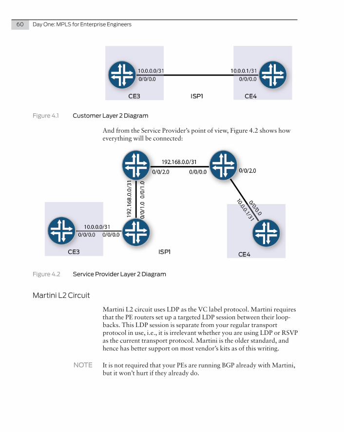
60 Day One: MPLS for Enterprise Engineers
Figure 4.1 Customer Layer 2 Diagram
And from the Service Provider’s point of view, Figure 4.2 shows how everything will be connected:
Figure 4.2 Service Provider Layer 2 Diagram
Martini L2 Circuit
Martini L2 circuit uses LDP as the VC label protocol. Martini requires that the PE routers set up a targeted LDP session between their loop-backs. This LDP session is separate from your regular transport protocol in use, i.e., it is irrelevant whether you are using LDP or RSVP as the current transport protocol. Martini is the older standard, and hence has better support on most vendor’s kits as of this writing.
NOTE It is not required that your PEs are running BGP already with Martini, but it won’t hurt if they already do.
Chapter 4: Layer 2 VPN 61
Customer Configuration
The customer has enabled OSPF on its WAN interfaces and its loop-backs. Both customer WAN interfaces are on the same subnet:
root@CE3> show configuration interfaces ge-0/0/0unit 0 { family inet { address 10.0.0.0/31; }}
root@CE3> show configuration protocols ospfarea 0.0.0.0 { interface lo0.0; interface ge-0/0/0.0;}
Service Provider Configuration
For the Service Provider configuration, Martini L2 circuits are created under the protocols stanza. There is no routing-instance created.
root@PE3> show configuration protocols l2circuitneighbor 172.16.0.2 { interface ge-0/0/0.0 { virtual-circuit-id 1; }}
The customer-facing interface is enabled under the l2 circuit stanza and specified a circuit-id. Both PEs need to agree on the virtual-circuit ID for the circuit to come up.
For Martini, you need to manually specify the remote PEs loopback address in order for the targeted LDP session to come up.
If you’re only running RSVP in the core, you need to enable LDP on the loopback interfaces. If you’re already running LDP in the core, then as long as LDP is already enabled on the loopback, the session will come up.
Finally, any Layer 3 configuration on the CE-facing interface needs to be removed. The encapsulation needs to change to family CCC on both the main interface and subinterface:
root@PE3> show configuration interfaces ge-0/0/0encapsulation ethernet-ccc;unit 0 { family ccc;}
62 Day One: MPLS for Enterprise Engineers
There is no BGP configuration required for the above.
Service Provider Verification
To verify that the L2 circuit is up:
root@PE3> show l2circuit connectionsLayer-2 Circuit Connections:
Legend for connection status (St)EI -- encapsulation invalid NP -- interface h/w not presentMM -- mtu mismatch Dn -- downEM -- encapsulation mismatch VC-Dn -- Virtual circuit DownCM -- control-word mismatch Up -- operationalVM -- vlan id mismatch CF -- Call admission control failureOL -- no outgoing label IB -- TDM incompatible bitrateNC -- intf encaps not CCC/TCC TM -- TDM misconfigurationBK -- Backup Connection ST -- Standby ConnectionCB -- rcvd cell-bundle size bad SP -- Static PseudowireLD -- local site signaled down RS -- remote site standbyRD -- remote site signaled down HS -- Hot-standby ConnectionXX -- unknown
Legend for interface statusUp -- operationalDn -- downNeighbor: 172.16.0.2 Interface Type St Time last up # Up trans ge-0/0/0.0(vc 1) rmt Up Jan 16 05:34:46 2014 1 Remote PE: 172.16.0.2, Negotiated control-word: Yes (Null) Incoming label: 299776, Outgoing label: 299776 Negotiated PW status TLV: No Local interface: ge-0/0/0.0, Status: Up, Encapsulation: ETHERNET Flow Label Transmit: No, Flow Label Receive: No
You can see that Junos gives you a lot of information, which helps when a circuit won’t come up. Key here is that Junos will only set up the LDP session once the local CE interface is up; if the link to the customer is down, no LDP label is signaled.
Customer Traffic Forwarding
First, note the VC label used for this circuit:
root@PE3> show l2circuit connections | find NeighborNeighbor: 172.16.0.2 Interface Type St Time last up # Up trans ge-0/0/0.0(vc 1) rmt Up Jan 16 05:34:46 2014 1 Remote PE: 172.16.0.2, Negotiated control-word: Yes (Null) Incoming label: 299776, Outgoing label: 299776 Negotiated PW status TLV: No Local interface: ge-0/0/0.0, Status: Up, Encapsulation: ETHERNET Flow Label Transmit: No, Flow Label Receive: No
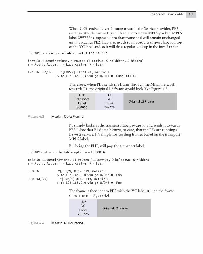
Chapter 4: Layer 2 VPN 63
When CE3 sends a Layer 2 frame towards the Service Provider, PE3 encapsulates the entire Layer 2 frame into a new MPLS packet. MPLS label 299776 is imposed onto that frame and will remain unchanged until it reaches PE2. PE3 also needs to impose a transport label on top of the VC label and so it will do a regular lookup in the inet.3 table:
root@PE3> show route table inet.3 172.16.0.2
inet.3: 4 destinations, 4 routes (4 active, 0 holddown, 0 hidden)+ = Active Route, - = Last Active, * = Both
172.16.0.2/32 *[LDP/9] 01:23:44, metric 1 > to 192.168.0.3 via ge-0/0/1.0, Push 300016
Therefore, when PE3 sends the frame through the MPLS network towards P1, the original L2 frame would look like Figure 4.3.
Figure 4.3 Martini Core Frame
P1 simply looks at the transport label, swaps it, and sends it towards PE2. Note that P1 doesn’t know, or care, that the PEs are running a Layer 2 service. It’s simply forwarding frames based on the transport MPLS label.
P1, being the PHP, will pop the transport label:
root@P1> show route table mpls label 300016
mpls.0: 11 destinations, 11 routes (11 active, 0 holddown, 0 hidden)+ = Active Route, - = Last Active, * = Both
300016 *[LDP/9] 01:28:39, metric 1 > to 192.168.0.0 via ge-0/0/2.0, Pop300016(S=0) *[LDP/9] 01:28:39, metric 1 > to 192.168.0.0 via ge-0/0/2.0, Pop
The frame is then sent to PE2 with the VC label still on the frame shown here in Figure 4.4.
Figure 4.4 Martini PHP Frame
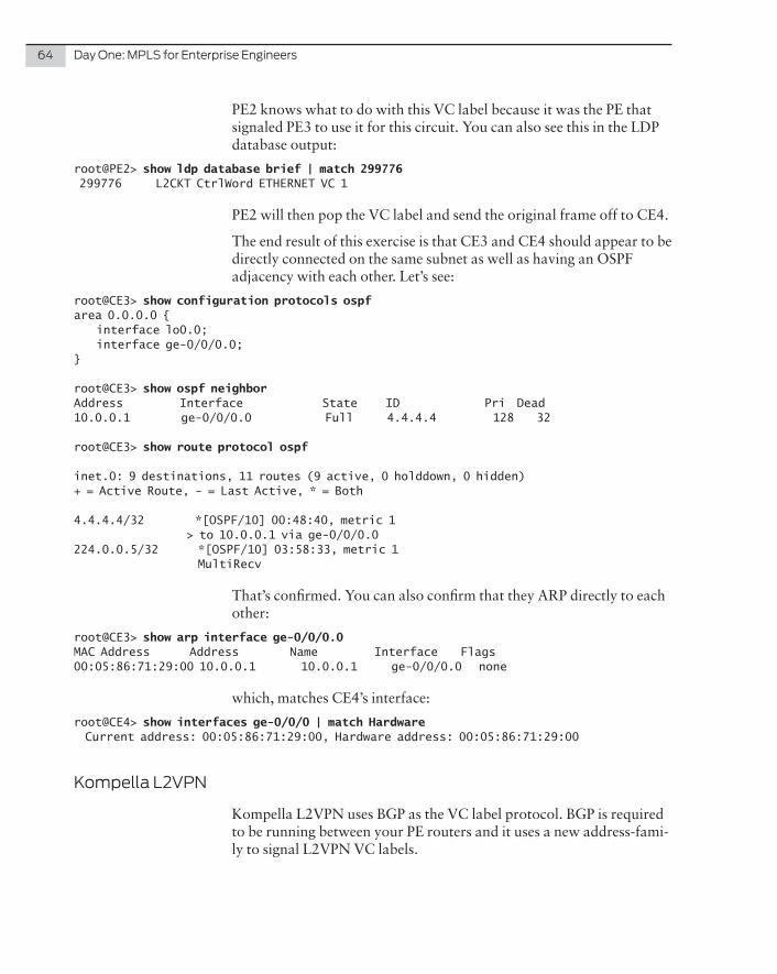
64 Day One: MPLS for Enterprise Engineers
PE2 knows what to do with this VC label because it was the PE that signaled PE3 to use it for this circuit. You can also see this in the LDP database output:
root@PE2> show ldp database brief | match 299776 299776 L2CKT CtrlWord ETHERNET VC 1
PE2 will then pop the VC label and send the original frame off to CE4.
The end result of this exercise is that CE3 and CE4 should appear to be directly connected on the same subnet as well as having an OSPF adjacency with each other. Let’s see:
root@CE3> show configuration protocols ospfarea 0.0.0.0 { interface lo0.0; interface ge-0/0/0.0;}
root@CE3> show ospf neighborAddress Interface State ID Pri Dead10.0.0.1 ge-0/0/0.0 Full 4.4.4.4 128 32
root@CE3> show route protocol ospf
inet.0: 9 destinations, 11 routes (9 active, 0 holddown, 0 hidden)+ = Active Route, - = Last Active, * = Both
4.4.4.4/32 *[OSPF/10] 00:48:40, metric 1 > to 10.0.0.1 via ge-0/0/0.0224.0.0.5/32 *[OSPF/10] 03:58:33, metric 1 MultiRecv
That’s confirmed. You can also confirm that they ARP directly to each other:
root@CE3> show arp interface ge-0/0/0.0MAC Address Address Name Interface Flags00:05:86:71:29:00 10.0.0.1 10.0.0.1 ge-0/0/0.0 none
which, matches CE4’s interface:
root@CE4> show interfaces ge-0/0/0 | match Hardware Current address: 00:05:86:71:29:00, Hardware address: 00:05:86:71:29:00
Kompella L2VPN
Kompella L2VPN uses BGP as the VC label protocol. BGP is required to be running between your PE routers and it uses a new address-fami-ly to signal L2VPN VC labels.
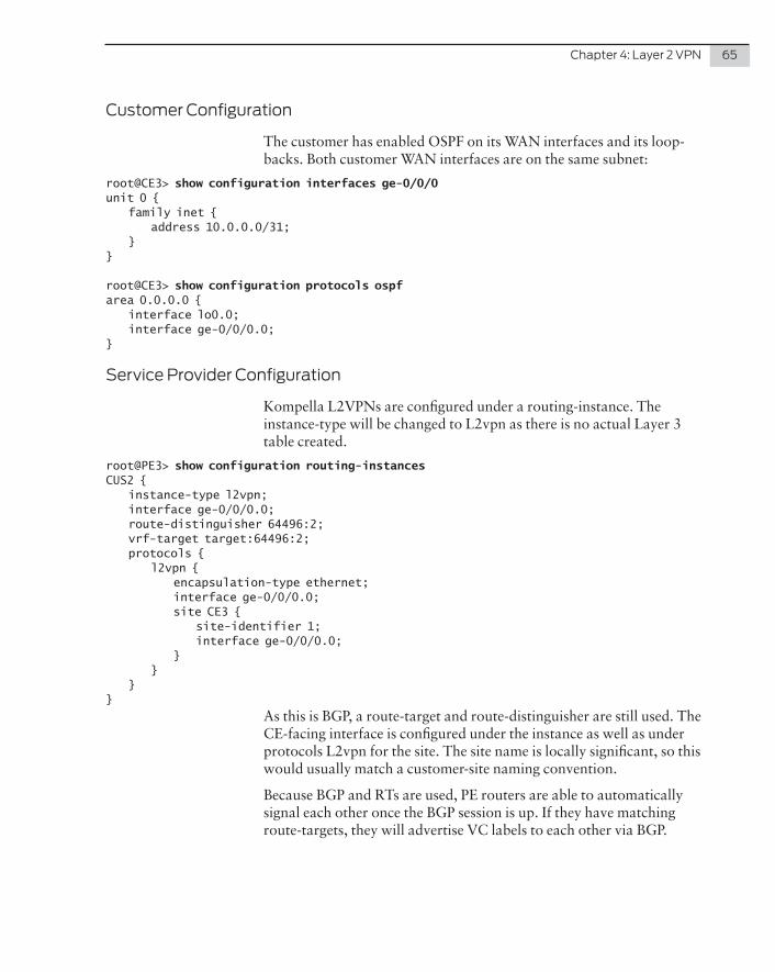
Chapter 4: Layer 2 VPN 65
Customer Configuration
The customer has enabled OSPF on its WAN interfaces and its loop-backs. Both customer WAN interfaces are on the same subnet:
root@CE3> show configuration interfaces ge-0/0/0unit 0 { family inet { address 10.0.0.0/31; }}
root@CE3> show configuration protocols ospfarea 0.0.0.0 { interface lo0.0; interface ge-0/0/0.0;}
Service Provider Configuration
Kompella L2VPNs are configured under a routing-instance. The instance-type will be changed to L2vpn as there is no actual Layer 3 table created.
root@PE3> show configuration routing-instancesCUS2 { instance-type l2vpn; interface ge-0/0/0.0; route-distinguisher 64496:2; vrf-target target:64496:2; protocols { l2vpn { encapsulation-type ethernet; interface ge-0/0/0.0; site CE3 { site-identifier 1; interface ge-0/0/0.0; } } }}
As this is BGP, a route-target and route-distinguisher are still used. The CE-facing interface is configured under the instance as well as under protocols L2vpn for the site. The site name is locally significant, so this would usually match a customer-site naming convention.
Because BGP and RTs are used, PE routers are able to automatically signal each other once the BGP session is up. If they have matching route-targets, they will advertise VC labels to each other via BGP.
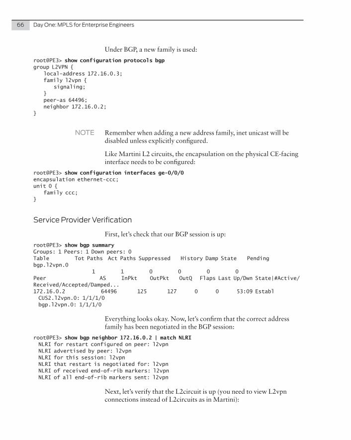
66 Day One: MPLS for Enterprise Engineers
Under BGP, a new family is used:
root@PE3> show configuration protocols bgpgroup L2VPN { local-address 172.16.0.3; family l2vpn { signaling; } peer-as 64496; neighbor 172.16.0.2;}
NOTE Remember when adding a new address family, inet unicast will be disabled unless explicitly configured.
Like Martini L2 circuits, the encapsulation on the physical CE-facing interface needs to be configured:
root@PE3> show configuration interfaces ge-0/0/0encapsulation ethernet-ccc;unit 0 { family ccc;}
Service Provider Verification
First, let’s check that our BGP session is up:
root@PE3> show bgp summaryGroups: 1 Peers: 1 Down peers: 0Table Tot Paths Act Paths Suppressed History Damp State Pendingbgp.l2vpn.0 1 1 0 0 0 0Peer AS InPkt OutPkt OutQ Flaps Last Up/Dwn State|#Active/Received/Accepted/Damped...172.16.0.2 64496 125 127 0 0 53:09 Establ CUS2.l2vpn.0: 1/1/1/0 bgp.l2vpn.0: 1/1/1/0
Everything looks okay. Now, let’s confirm that the correct address family has been negotiated in the BGP session:
root@PE3> show bgp neighbor 172.16.0.2 | match NLRI NLRI for restart configured on peer: l2vpn NLRI advertised by peer: l2vpn NLRI for this session: l2vpn NLRI that restart is negotiated for: l2vpn NLRI of received end-of-rib markers: l2vpn NLRI of all end-of-rib markers sent: l2vpn
Next, let’s verify that the L2circuit is up (you need to view L2vpn connections instead of L2circuits as in Martini):
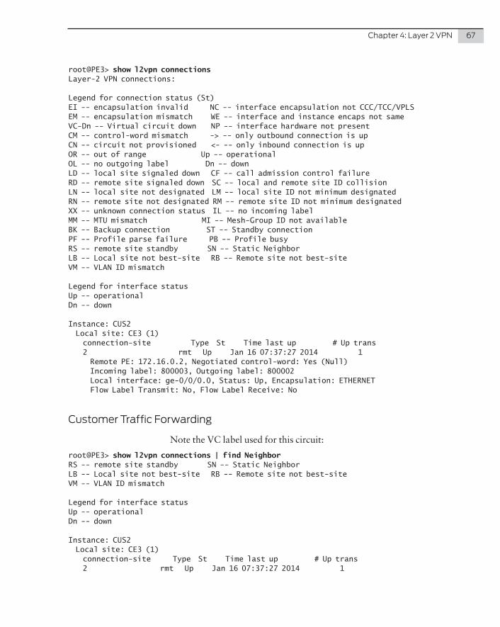
Chapter 4: Layer 2 VPN 67
root@PE3> show l2vpn connectionsLayer-2 VPN connections:
Legend for connection status (St)EI -- encapsulation invalid NC -- interface encapsulation not CCC/TCC/VPLSEM -- encapsulation mismatch WE -- interface and instance encaps not sameVC-Dn -- Virtual circuit down NP -- interface hardware not presentCM -- control-word mismatch -> -- only outbound connection is upCN -- circuit not provisioned <- -- only inbound connection is upOR -- out of range Up -- operationalOL -- no outgoing label Dn -- downLD -- local site signaled down CF -- call admission control failureRD -- remote site signaled down SC -- local and remote site ID collisionLN -- local site not designated LM -- local site ID not minimum designatedRN -- remote site not designated RM -- remote site ID not minimum designatedXX -- unknown connection status IL -- no incoming labelMM -- MTU mismatch MI -- Mesh-Group ID not availableBK -- Backup connection ST -- Standby connectionPF -- Profile parse failure PB -- Profile busyRS -- remote site standby SN -- Static NeighborLB -- Local site not best-site RB -- Remote site not best-siteVM -- VLAN ID mismatch
Legend for interface statusUp -- operationalDn -- down
Instance: CUS2 Local site: CE3 (1) connection-site Type St Time last up # Up trans 2 rmt Up Jan 16 07:37:27 2014 1 Remote PE: 172.16.0.2, Negotiated control-word: Yes (Null) Incoming label: 800003, Outgoing label: 800002 Local interface: ge-0/0/0.0, Status: Up, Encapsulation: ETHERNET Flow Label Transmit: No, Flow Label Receive: No
Customer Traffic Forwarding
Note the VC label used for this circuit:
root@PE3> show l2vpn connections | find NeighborRS -- remote site standby SN -- Static NeighborLB -- Local site not best-site RB -- Remote site not best-siteVM -- VLAN ID mismatch
Legend for interface statusUp -- operationalDn -- down
Instance: CUS2 Local site: CE3 (1) connection-site Type St Time last up # Up trans 2 rmt Up Jan 16 07:37:27 2014 1
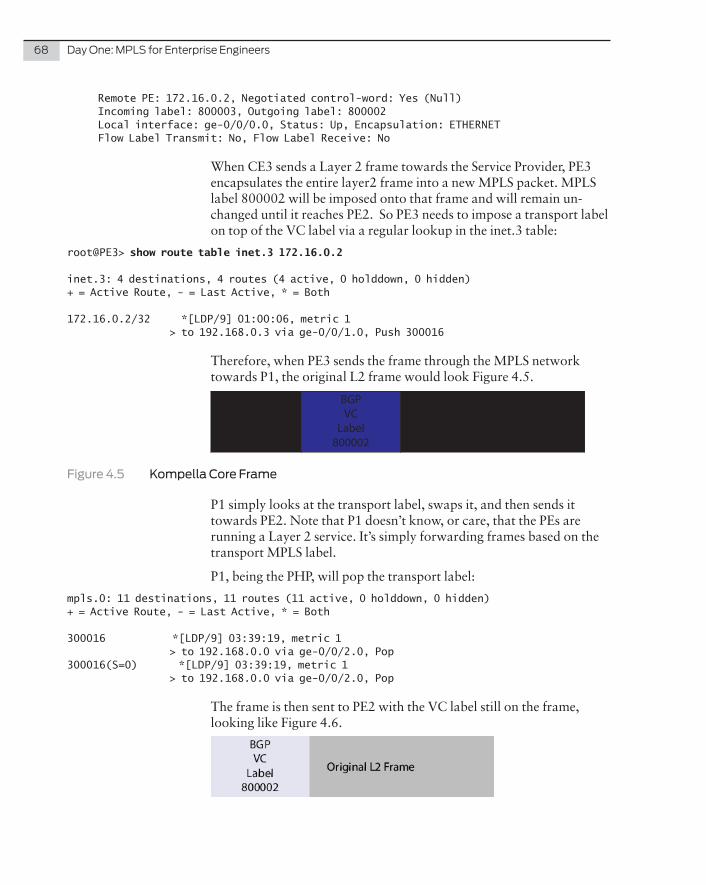
68 Day One: MPLS for Enterprise Engineers
Remote PE: 172.16.0.2, Negotiated control-word: Yes (Null) Incoming label: 800003, Outgoing label: 800002 Local interface: ge-0/0/0.0, Status: Up, Encapsulation: ETHERNET Flow Label Transmit: No, Flow Label Receive: No
When CE3 sends a Layer 2 frame towards the Service Provider, PE3 encapsulates the entire layer2 frame into a new MPLS packet. MPLS label 800002 will be imposed onto that frame and will remain un-changed until it reaches PE2. So PE3 needs to impose a transport label on top of the VC label via a regular lookup in the inet.3 table:
root@PE3> show route table inet.3 172.16.0.2
inet.3: 4 destinations, 4 routes (4 active, 0 holddown, 0 hidden)+ = Active Route, - = Last Active, * = Both
172.16.0.2/32 *[LDP/9] 01:00:06, metric 1 > to 192.168.0.3 via ge-0/0/1.0, Push 300016
Therefore, when PE3 sends the frame through the MPLS network towards P1, the original L2 frame would look Figure 4.5.
LDP Transport
Label 300016
BGP VC
Label 800002
Original L2 Frame
Figure 4.5 Kompella Core Frame
P1 simply looks at the transport label, swaps it, and then sends it towards PE2. Note that P1 doesn’t know, or care, that the PEs are running a Layer 2 service. It’s simply forwarding frames based on the transport MPLS label.
P1, being the PHP, will pop the transport label:
mpls.0: 11 destinations, 11 routes (11 active, 0 holddown, 0 hidden)+ = Active Route, - = Last Active, * = Both
300016 *[LDP/9] 03:39:19, metric 1 > to 192.168.0.0 via ge-0/0/2.0, Pop300016(S=0) *[LDP/9] 03:39:19, metric 1 > to 192.168.0.0 via ge-0/0/2.0, Pop
The frame is then sent to PE2 with the VC label still on the frame, looking like Figure 4.6.
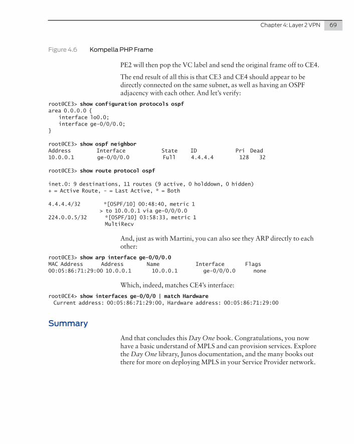
Chapter 4: Layer 2 VPN 69
Figure 4.6 Kompella PHP Frame
PE2 will then pop the VC label and send the original frame off to CE4.
The end result of all this is that CE3 and CE4 should appear to be directly connected on the same subnet, as well as having an OSPF adjacency with each other. And let’s verify:
root@CE3> show configuration protocols ospfarea 0.0.0.0 { interface lo0.0; interface ge-0/0/0.0;}
root@CE3> show ospf neighborAddress Interface State ID Pri Dead10.0.0.1 ge-0/0/0.0 Full 4.4.4.4 128 32
root@CE3> show route protocol ospf
inet.0: 9 destinations, 11 routes (9 active, 0 holddown, 0 hidden)+ = Active Route, - = Last Active, * = Both
4.4.4.4/32 *[OSPF/10] 00:48:40, metric 1 > to 10.0.0.1 via ge-0/0/0.0224.0.0.5/32 *[OSPF/10] 03:58:33, metric 1 MultiRecv
And, just as with Martini, you can also see they ARP directly to each other:
root@CE3> show arp interface ge-0/0/0.0MAC Address Address Name Interface Flags00:05:86:71:29:00 10.0.0.1 10.0.0.1 ge-0/0/0.0 none
Which, indeed, matches CE4’s interface:
root@CE4> show interfaces ge-0/0/0 | match Hardware Current address: 00:05:86:71:29:00, Hardware address: 00:05:86:71:29:00
Summary
And that concludes this Day One book. Congratulations, you now have a basic understand of MPLS and can provision services. Explore the Day One library, Junos documentation, and the many books out there for more on deploying MPLS in your Service Provider network.


![Case Study - NANOG Archive...• In Junos, All routers need “ipv6-tunneling” under [protocols mpls] • So that IPv6 routes are resolved over the LSP tunnels. • BGP • BGP needs](https://img.pdfslide.us/doc/110x75/6101e8379100e84c4e7217e5/case-study-nanog-archive-a-in-junos-all-routers-need-aoeipv6-tunnelinga.jpg)