Embed Size (px)
Citation preview
Juniper Validated Solutions
Build an elegant dynamic overlay
network using features such as
Dynamic GRE and IPsec to enable
secure, flexible services over an
IP-only WAN and then extend the
overlay to Cloud DC Interconnect
with new Junos 14.1 features such
as EVPN.
By Russell Kelly
DAY ONE: BUILDING DYNAMIC OVERLAY SERVICE-AWARE NETWORKS
Juniper Networks Books are singularly focused on network productivity and efficiency. Peruse the complete library at www.juniper.net/books.
Published by Juniper Networks Books
DAY ONE: BUILDING DYNAMIC OVERLAY SERVICE-AWARE NETWORKS
IP backbones can no longer be designed simply to transport IP packets. Instead, Inter-net Protocol (IP) backbones must be capable of providing multiple Layer 2 and Layer 3 secure services over a single physical IP-only infrastructure, using techniques such as secure transport layers. How does one achieve this flexibility? The answer is to overlay, or tunnel in traditional parlance, but because today’s networks are required to be highly scalable and extremely dynamic, the solution needs to be simple, scalable, and flexible.
Day One: Building Dynamic Overlay Service-Aware Networks details two major use cases: a scaled WAN solution, both with and without IPsec; and, a data center interconnect (DCI) use case where Ethernet VPN (EVPN) is employed to showcase the control-plane MAC learning, and Layer 2 and Layer 3 unification (MAC+IP binding) capabilities.
The author shows off the unique capabilities of the Juniper MX and SRX Series in this lab-friendly Day One book providing step-by-step instructions. Use the configurations included and build a reliable and scalable network without the high administrative overhead of provisioning hundreds of individual tunnels or connections.
IT’S DAY ONE AND YOU HAVE A JOB TO DO, SO LEARN HOW TO:
n Better understand the challenges facing Enterprises and SPs alike when running
services over IP backbones in WAN and DCI topologies.
n Better understand dynamic overlay features solutions available across Junos
platforms.
n Know and use special Junos commands related to security, MPLS VPNs,
forwarding policies, and virtualization.
n Be able to deploy MX and SRX series platforms in a variety of roles.
n Build a working model in your lab.
ISBN 978-9367799321
9 789367 799321
5 1 6 0 0
By Russell Kelly
Day One: Building Dynamic Overlay Service-Aware Networks
Chapter 1: Design Overview . . . . . . . . . . . . . . . . . . . . . . . . . . . . . . . . . . . . . . . . . . . . . . . . . . . . . . . . . . . . . 9
Chapter 2: Overlay Use Case Overviews . . . . . . . . . . . . . . . . . . . . . . . . . . . . . . . . . . . . . . . . . . . . . . . . .17
Chapter 3: Comparison with Cisco LISP Use Cases . . . . . . . . . . . . . . . . . . . . . . . . . . . . . . . . . . . . . 29
Chapter 4: Implementation Steps: Any-to-Any Overlay Solution . . . . . . . . . . . . . . . . . . . . . . . . 33
Chapter 5: Implementation Steps: Encrypted Hub-Spoke IP Overlay Solution . . . . . . . . . . . 57
Chapter 6: Integrating Virtualized Services (or Virtualized Remote Sites) Into
the Overlay Topology . . . . . . . . . . . . . . . . . . . . . . . . . . . . . . . . . . . . . . . . . . . . . . . . . . . . . . . . . . . . . . . . . .89
Chapter 7: DCI Use Case with VM Mobility Over IP with EVPN and Layer 3
(IP) Awareness (Junos 14 .1) . . . . . . . . . . . . . . . . . . . . . . . . . . . . . . . . . . . . . . . . . . . . . . . . . . . . . . . . . . . . 97
Build an elegant dynamic overlay network using features such as Dynamic GRE and iPsec to enable secure, flexible services over an iP-only wAN and then extend the overlay to Cloud DC Interconnect with new Junos 14 .1 features such as EVPN .
© 2014 by Juniper Networks, Inc. All rights reserved. Juniper Networks, Junos, Steel-Belted Radius, NetScreen, and ScreenOS are registered trademarks of Juniper Networks, Inc. in the United States and other countries. The Juniper Networks Logo, the Junos logo, and JunosE are trademarks of Juniper Networks, Inc. All other trademarks, service marks, registered trademarks, or registered service marks are the property of their respective owners. Juniper Networks assumes no responsibility for any inaccuracies in this document. Juniper Networks reserves the right to change, modify, transfer, or otherwise revise this publication without notice. Published by Juniper Networks BooksAuthor: Russell KellyTechnical Reviewers: Eddie ParraEditor in Chief: Patrick AmesCopyeditor and Proofer: Nancy KoerbelJ-Net Community Manager: Julie Wider
ISBN: 978-1-936779-93-2 (print)Printed in the USA by Vervante Corporation.
ISBN: 978-1-936779-94-9 (ebook)
Version History: v1, June 2014 2 3 4 5 6 7 8 9 10
This book is available in a variety of formats at: http://www.juniper.net/dayone.
About the Author Russell Kelly is a networking expert with fifteen years experience in the IT telecom and networking industries. He has worked in the leading financials and for Fortune 500 companies for ten years throughout Europe and the US designing their global networks and high perfor-mance trading networks. Russell supports the top financials institutions and service providers, designing and focusing on routing and switching and advanced networking technologies, leading the top Global Enterprise and SP Edge customer engagements and regularly speaking at external industry events. Upon joining Juniper in 2011, Russell has worked as a Senior PLM and Solutions Architect, focusing on Datacenter Edge and Enterprise WAN Edge designs as well as SP WAN Services
Russell holds a B.Eng and B.Sc degree in Computing from Auckland University, and a Masters in Information Systems from RMIT in Melbourne. He also holds multiple industry certifications including his CCIE.
iv

Welcome to Day One
This book is part of a growing library of Day One books, produced and published by Juniper Networks Books.
Day One books were conceived to help you get just the information that you need on day one. The series covers Junos OS and Juniper Networks networking essentials with straightforward explanations, step-by-step instructions, and practical examples that are easy to follow.
The Day One library also includes a slightly larger and longer suite of This Week books, whose concepts and test bed examples are more similar to a weeklong seminar.
You can obtain either series, in multiple formats:
� Download a free PDF edition at http://www.juniper.net/dayone.
� Get the ebook edition for iPhones and iPads from the iTunes Store. Search for Juniper Networks Books.
� Get the ebook edition for any device that runs the Kindle app (Android, Kindle, iPad, PC, or Mac) by opening your device's Kindle app and going to the Kindle Store. Search for Juniper Networks Books.
� Purchase the paper edition at either Vervante Corporation (www.vervante.com) or Amazon (amazon.com) for between $12-$28, depending on page length.
� Note that Nook, iPad, and various Android apps can also view PDF files.
� If your device or ebook app uses .epub files, but isn't an Apple product, open iTunes and download the .epub file from the iTunes Store. You can now drag and drop the file out of iTunes onto your desktop and sync with your .epub device.
v
vi
Audience and Scope of This Book
This book is intended for architects and engineers working in the planning and the design of High-IQ Service Provider and Enterprise networks. It describes the principles of secure WAN overlay architecture for Layer 2 and Layer 3 services for IPv4 and IPv6 unicast traffic by detailing the requirements that network architects need to successfully deploy this overlay, design, and configuration of network elements.
The scope of this book spans the functionality available in Junos up to the capabilities of the MX 3D Series devices.
Chapters 1-2 are overviews of the architecture, Chapter 3 is a compara-tive analysis between Cisco and Juniper, Chapters 4-5 are implementa-tion instructions for that architecture, Chapter 6 integrates virtualized services, and Chapter 7 is a use case highlighting Junos 14.1.
What You Need to Know Before Reading This Book
Before reading this book, you should be familiar with the basic adminis-trative functions of the Junos operating system, including the ability to work with operational commands and to read, understand, and change Junos configurations. There are several books in the Day One library on learning Junos, at www.juniper.net/dayone.
This book makes a few assumptions about you, the reader:
� You have a basic understanding of the Internet Protocol (IP) versions 4 and 6.
� You have an understanding of IPsec and GRE tunneling methods.
� You have a basic working knowledge of MPLS and MPLS VPN services.
� You have access to a lab with at least the following components: One M/MX or SRX Series router, and one Ethernet switch.
What You Will Learn by Reading This Book
� Better understand the challenges facing Enterprises and SPs alike when running services over IP backbones in the WAN and DCI topologies.
� Better understand dynamic overlay features solutions available across Junos platforms.
vii
� Know and use special Junos commands related to security, MPLS VPNs, forwarding policies, virtualization.
� Be able to deploy MX and SRX series platforms in a variety of roles.
� Build a working model in your lab.
Information Experience
This Day One book is singularly focused on one aspect of networking technology. There are other sources at Juniper Networks, from white papers to webinairs to online forums such as J-Net (forums.juniper.net). Look for sidebars throughout this book for direct access to other superb sources of information.
Copy and Paste Edition for Copying Configurations
This Day One book has a companion Copy and Paste Edition you can use to copy the configurations and paste into your lab terminal. The file can be found on this book’s landing page at www.juniper.net/dayone.
Preface
IP backbones can no longer be designed simply to transport IP packets. Instead, Internet Protocol (IP) backbones must be capable of providing multiple IP services over a single physical infrastructure, using tech-niques such as secure transport layers. How does one achieve this flexibility? The answer is to overlay, or tunnel in traditional parlance, but because today’s networks are required to be highly scalable and extremely dynamic, the solution needs to be simple, scalable, and flexible..
In addition to these requirements, networks need to support the mission-critical, time-sensitive applications that your modern network requires, and must meet new demands for applications, services, and bandwidth. Multiprotocol Label Switching (MPLS), when tunneled over an IP backbone, provides the mechanism to offer rich IP services and transport capabilities to the routing infrastructure. Providing virtualized services over an IP core offers a flexible, cost-efficient WAN design that is simple to configure yet still maintains support for core infrastructure services and security. Unfortunately the traditional
viii
solution to this problem, using GRE and IPsec tunnels, is inherently point-to-point in nature and is thus difficult to scale easily.
This Day One book details an elegant solution to provide a secure multipoint service-like Layer 3 VPN and VPLS over a point-to-point technology like GRE or IPsec in a reliable and scalable fashion without the high administrative overhead of provisioning tens or hundreds of individual tunnels or connections. This is achieved by utilizing the unique capabilities of Juniper MX Series routers and Junos – namely Dynamic GRE, which builds an any-to-any PE peering over an IP core and dynamic end-point IPsec, which supports the standing-up and tearing-down of VPN connections dynamically without user interven-tion.
This topology must support the following services:
� VPLS: An Ethernet-based service, offers users a multipoint Layer 2 VPN
� EVPN: Control plane-based learning Layer 2 Ethernet-based multipoint solution
� Layer 3 VPN: Provides customer separation using MPLS for Layer 3 IP domain
These technologies provide a recognizable and well-understood interface that is easy to troubleshoot and utilize in order to enable secure, flexible services over an IP-only WAN.
The book details two major use cases, a scaled WAN solution, both with and without IPsec, and a data center interconnect (DCI) use case where Ethernet VPN (EVPN) is employed to showcase the control-plane MAC learning and Layer 2 and Layer 3 unification (MAC+IP binding) capabilities.
NOTE This book assumes two classes of IP WAN, one that is inherently public and untrusted, for example, the Internet, where IPsec must be used to ensure privacy, and another class that is deemed private but is IP only. Two examples of such a situation exist for Service Providers who need to tunnel over another provider’s core without using carrier support carrier (CSC), or for enterprises who have not, or can not enable MPLS on the private WAN, or who procure an IP service from a provider such as an Layer 3 VPN, and therefore only have IP WAN service capabilities.
The primary service extension being added in this book’s design of a virtual overlay is the ability for users to add their own virtualization atop an existing IP infrastructure. This capability is becoming a de facto business requirement that allows users to easily and securely add new cloud, or hosted, services into the domain.
The design provides a solution of a dynamic virtualized WAN with a unified BGP control plane that will provide you with a topology that is flexible enough to provide any service (Layer 2 or Layer 3), that can integrate chained services, and that can turn up new, hosted services (hosted data center environments) throughout the topology using SDN virtualization and transport concepts. The design is applicable to SP WAN, managed CPE environments, and Cloud and Enterprise customers.
Design Specifics
One of the fundamental principles in this design of a virtual overlay is the assumption that you only have IP transport, and then the book takes it one step further and assumes this IP transport is untrusted (for example, the Internet) and the traffic must be encrypted.
The details of the specific GRE encapsulation feature that is used will be covered later in the book, so let’s briefly investigate the concept and packet structure when encapsulating MPLS VPNs in GRE.
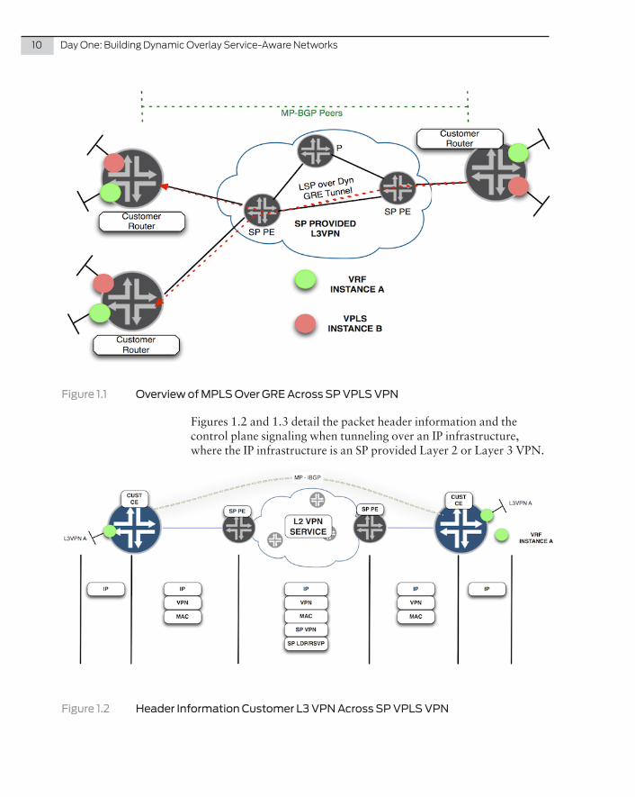
Figure 1.1 illustrates the roles of the CE and SP PE routers when a customer is overlaying their own private VPNs across the SP IP core.
Chapter 1
Design Overview
10 DayOne:BuildingDynamicOverlayService-AwareNetworks
Figure 1.1 Overview of MPLS Over GRE Across SP VPLS VPN
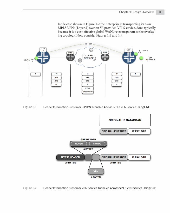
Figures 1.2 and 1.3 detail the packet header information and the control plane signaling when tunneling over an IP infrastructure, where the IP infrastructure is an SP provided Layer 2 or Layer 3 VPN.
Figure 1.2 Header Information Customer L3 VPN Across SP VPLS VPN
Chapter1:DesignOverview 11
In the case shown in Figure 1.2 the Enterprise is transporting its own MPLS VPNs (Layer 3) over an SP-provided VPLS service, done typically because it is a cost-effective global WAN, yet transparent to the overlay-ing topology. Now consider Figures 1.3 and 1.4.
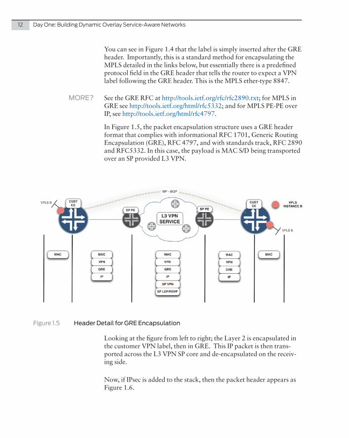
Figure 1.3 Header Information Customer L3 VPN Tunneled Across SP L3 VPN Service Using GRE
Figure 1.4 Header Information Customer VPN Service Tunneled Across SP L3 VPN Service Using GRE
12 DayOne:BuildingDynamicOverlayService-AwareNetworks
You can see in Figure 1.4 that the label is simply inserted after the GRE header. Importantly, this is a standard method for encapsulating the MPLS detailed in the links below, but essentially there is a predefined protocol field in the GRE header that tells the router to expect a VPN label following the GRE header. This is the MPLS ether-type 8847.
MORE? See the GRE RFC at http://tools.ietf.org/rfc/rfc2890.txt; for MPLS in GRE see http://tools.ietf.org/html/rfc5332; and for MPLS PE-PE over IP, see http://tools.ietf.org/html/rfc4797.
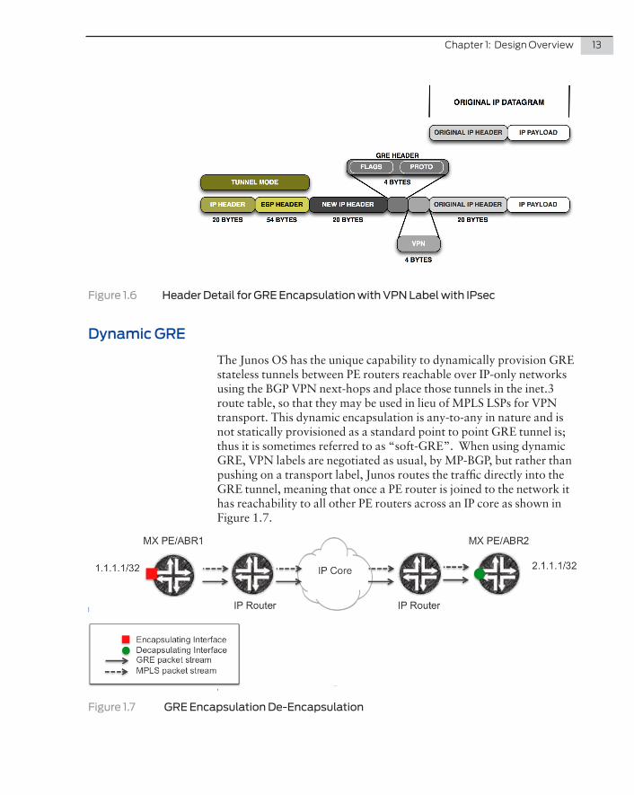
In Figure 1.5, the packet encapsulation structure uses a GRE header format that complies with informational RFC 1701, Generic Routing Encapsulation (GRE), RFC 4797, and with standards track, RFC 2890 and RFC5332. In this case, the payload is MAC S/D being transported over an SP provided L3 VPN.
Figure 1.5 Header Detail for GRE Encapsulation
Looking at the figure from left to right; the Layer 2 is encapsulated in the customer VPN label, then in GRE. This IP packet is then trans-ported across the L3 VPN SP core and de-encapsulated on the receiv-ing side.
Now, if IPsec is added to the stack, then the packet header appears as Figure 1.6.
Chapter1:DesignOverview 13
Figure 1.6 Header Detail for GRE Encapsulation with VPN Label with IPsec
Dynamic GRE
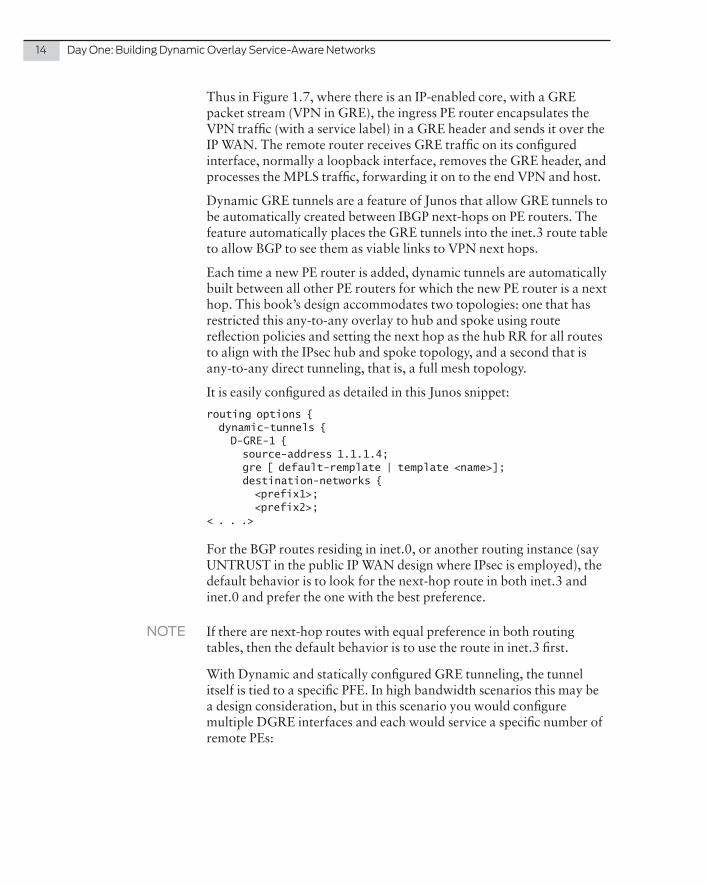
The Junos OS has the unique capability to dynamically provision GRE stateless tunnels between PE routers reachable over IP-only networks using the BGP VPN next-hops and place those tunnels in the inet.3 route table, so that they may be used in lieu of MPLS LSPs for VPN transport. This dynamic encapsulation is any-to-any in nature and is not statically provisioned as a standard point to point GRE tunnel is; thus it is sometimes referred to as “soft-GRE”. When using dynamic GRE, VPN labels are negotiated as usual, by MP-BGP, but rather than pushing on a transport label, Junos routes the traffic directly into the GRE tunnel, meaning that once a PE router is joined to the network it has reachability to all other PE routers across an IP core as shown in Figure 1.7.
t
Figure 1.7 GRE Encapsulation De-Encapsulation
14 DayOne:BuildingDynamicOverlayService-AwareNetworks
Thus in Figure 1.7, where there is an IP-enabled core, with a GRE packet stream (VPN in GRE), the ingress PE router encapsulates the VPN traffic (with a service label) in a GRE header and sends it over the IP WAN. The remote router receives GRE traffic on its configured interface, normally a loopback interface, removes the GRE header, and processes the MPLS traffic, forwarding it on to the end VPN and host.
Dynamic GRE tunnels are a feature of Junos that allow GRE tunnels to be automatically created between IBGP next-hops on PE routers. The feature automatically places the GRE tunnels into the inet.3 route table to allow BGP to see them as viable links to VPN next hops.
Each time a new PE router is added, dynamic tunnels are automatically built between all other PE routers for which the new PE router is a next hop. This book’s design accommodates two topologies: one that has restricted this any-to-any overlay to hub and spoke using route reflection policies and setting the next hop as the hub RR for all routes to align with the IPsec hub and spoke topology, and a second that is any-to-any direct tunneling, that is, a full mesh topology.
It is easily configured as detailed in this Junos snippet:
routing options { dynamic-tunnels { D-GRE-1 { source-address 1.1.1.4; gre [ default-remplate | template <name>]; destination-networks { <prefix1>; <prefix2>;< . . .>
For the BGP routes residing in inet.0, or another routing instance (say UNTRUST in the public IP WAN design where IPsec is employed), the default behavior is to look for the next-hop route in both inet.3 and inet.0 and prefer the one with the best preference.
NOTE If there are next-hop routes with equal preference in both routing tables, then the default behavior is to use the route in inet.3 first.
With Dynamic and statically configured GRE tunneling, the tunnel itself is tied to a specific PFE. In high bandwidth scenarios this may be a design consideration, but in this scenario you would configure multiple DGRE interfaces and each would service a specific number of remote PEs:

Chapter1:DesignOverview 15
� The Trio PFE (MPC3) for Juniper MX Series is capable of hosting a 10Gbps full-duplex tunnel interface without disabling ports, but the GRE tunnel must be assigned to a specific PFE. See the configuration.
� The Snorkel (MPC4) supports a total of four inline tunnels per line card, one per PIC. The configuration lets the user select the bandwidth for a tunnel: 1G, 10G, 20G, 30G, 40G, or unspeci-fied. When the tunnel bandwidth is not specified, the maximum tunnel bandwidth is 60G.
chassis { fpc <0..19> { pic <0..3> { tunnel-services { bandwidth <1g|10g|20g|30g|40g|100g>
Now let’s investigate how this specific solution is put together.

16 DayOne:BuildingDynamicOverlayService-AwareNetworks
This book outlines three use cases for the WAN:
� An unencrypted any-to-any IP overlay solution.
� A second approach where IPsec is required as an integrated service on the router.
� A data center interconnect (DCI) overlay solution that leverages EVPN and that can optimize traffic flows when compute resources move between datacenter locations.
As mentioned previously, the unencrypted solution is used when customers trust the IP transport and therefore only need GRE or IP encapsulation to enable service overlay, while the second solution is used when the IP transport is untrusted, and IPsec must be employed atop of IP encapsulation to ensure data privacy.
Let’s review the use cases one by one.
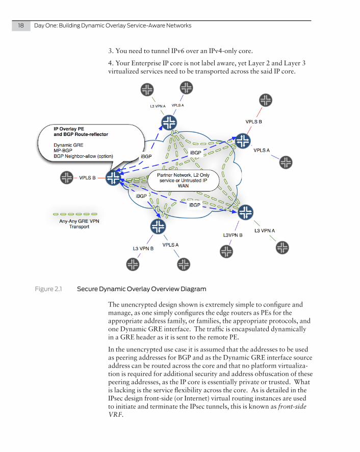
Unencrypted Any-to-Any IP Overlay Solution
Figure 2.1 illustrates the any-to-any transport over an IP core (assumed IPv4). Although the topology may look generic, the use cases for tunneling over the core (without encryption) are:
1. A Provider needs to transport their own L2 and IP VPN services over the partner network and Carrier Supporting Carrier (CSC) is not available.
2. The Layer 2-only core and the edge devices need to overlay Layer 3 services – in this case the C-PEs (blue) would be VLAN-connected to the core.
Chapter 2
Overlay Use Case Overviews
18 DayOne:BuildingDynamicOverlayService-AwareNetworks
3. You need to tunnel IPv6 over an IPv4-only core.
4. Your Enterprise IP core is not label aware, yet Layer 2 and Layer 3 virtualized services need to be transported across the said IP core.
Figure 2.1 Secure Dynamic Overlay Overview Diagram
The unencrypted design shown is extremely simple to configure and manage, as one simply configures the edge routers as PEs for the appropriate address family, or families, the appropriate protocols, and one Dynamic GRE interface. The traffic is encapsulated dynamically in a GRE header as it is sent to the remote PE.
In the unencrypted use case it is assumed that the addresses to be used as peering addresses for BGP and as the Dynamic GRE interface source address can be routed across the core and that no platform virtualiza-tion is required for additional security and address obfuscation of these peering addresses, as the IP core is essentially private or trusted. What is lacking is the service flexibility across the core. As is detailed in the IPsec design front-side (or Internet) virtual routing instances are used to initiate and terminate the IPsec tunnels, this is known as front-side VRF.
Chapter2:OverlayUseCaseOverviews 19
NOTE The SRX is a flow-based forwarding platform by default. In the GRE-only design there is no need for L4-L7 flow-based services, so these can be disabled globally on the platform. This simplifies the configuration of the system and the solution – this option will be detailed in the GRE-only overlay – while in the secure overlay the selective packet forwarding configuration option will be detailed.
MORE? For further information on the concept of packet versus flow-based forwarding and selective packet mode please refer to the following app note: http://www.juniper.net/us/en/local/pdf/app-notes/3500192-en.pdf; documentation http://www.juniper.net/techpubs/software/junos-security/junos-security10.1/junos-security-admin-guide/packet-flow-based-fwd-section.html; or book, http://www.juniper.net/us/en/training/jnbooks/srx-series.html.
Head-EndBranch 1 - MX
Ethernet
Private Core
Lo0172.20.1.1
OSPF OSPF
(L3 Transport)Core
Protocol
BGP Peering uses loopback addresses - MPLS over GRE data traffic is encapsulated in the GRE header (source and destination == loopback addfresses
Tunneled/Private Protocol
Dynamic GRE Tunnelhead-end 1 source = 172.31.255.31branch source = 172.20.1.1branch source = 172.20.1.2branch source = 172.20.1.3
MP-BGP Peering
L2 ServiceIPv6 VPNIPv4 VPN
Branch 2 - M7i
Private Core
Lo0172.20.1.2
Private Core
Lo0172.20.1.3
inet.0
inet.0
Private IP or L2 BB
inet.0
lo0.0 172.31.255.31
Branch 3 - M7i
VPLS1
VPLS1
VPLS1
L2 ServiceIPv6 VPNIPv4 VPN
L2 ServiceIPv6 VPNIPv4 VPN
VPLS1
vRouter
Ubuntu
DC L3 Fabric inet.0Dual-Stack-IP-
VPN Dual-Stack-IP-
VPN
Dual-Stack-IP-VPN
Dual-Stack-IP-VPN
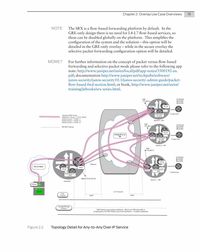
Figure 2.2 Topology Detail for Any-to-Any Over IP Service
20 DayOne:BuildingDynamicOverlayService-AwareNetworks
Figure 2.2 (also used in the implementation section) details the topology of the GRE any-to-any design (four routers shown). As illustrated, the overlay is dynamic and is a full mesh between PEs, with each router using its loopback address as both a BGP peering address and as the source for the local Dynamic GRE tunnel. The only address that needs to be advertised across the IP backbone is this loopback address; in this case OSPF is used, but it could be any IGP, or even BGP. The provider of the IP or Layer 2 backbone sees the routers as pure IP CE routers. In this case this backbone is Layer 2-only, and then the attachment circuit is Ethernet, or 802.1q-tagged Ethernet.
Additionally in this design – and in the secure overlay option – a virtual compute node has been added using the Juniper Contrail vRouter and MPLS over GRE terminating into the same routing instance as used by the remote sites.
MORE? For more information on the Contrail solution please refer to Day One: Understanding OpenContrail Architecture at www.juniper.net/books.
NOTE There are many ways to integrate virtual compute into an existing topology using Contrail’s vRouter. One method is to terminate the vRouters into their own VRF and connect to an existing VRF using Option-A type connectivity. Another is using Option B, where labels are exchanged between VRFs. This enables greater route control and facilitates route aggregation between VRFs. In this book, the vRouters are terminated into the same VRF as the remote sites, because scale is not an issue here.
Encrypted Hub-Spoke IP Overlay Solution
Now let’s investigate the secure overlay design. As shown in the over-view of the topology in Figure 2.3, the control plane is the same as before – using route reflectors – although an export policy must now be enabled to allow for communication via the hub. Additionally, mesh groups can be used to simplify the VPLS peering configuration.
The salient points with this design are:
� Dynamic End-Point IPsec on head-end.
� RRI injection configured on Hub.
� PKI Infrastructure on Hub and Spokes.
� Dynamic GRE configured on hub and spokes. Private loopbacks used for BGP peering.
� MP-BGP configured on all routers. Hub configured as a BGP RR.
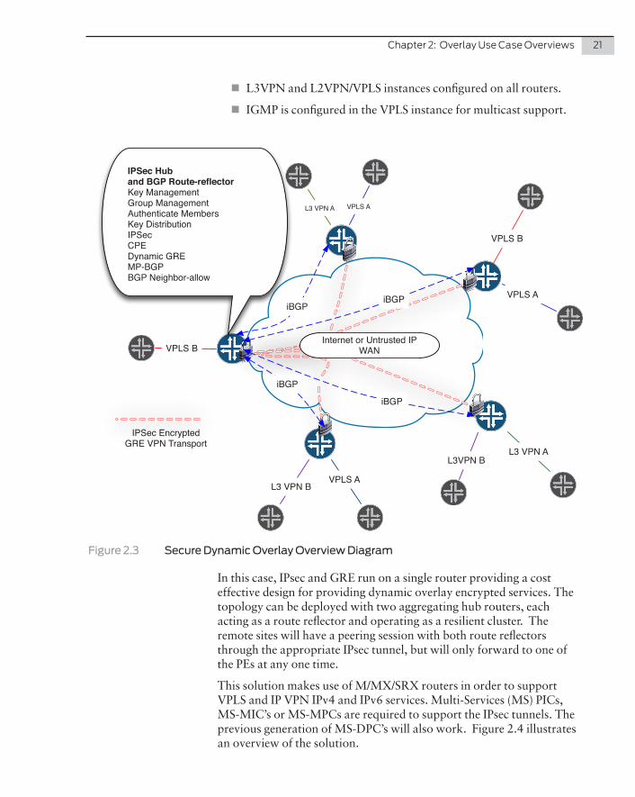
Chapter2:OverlayUseCaseOverviews 21
� L3VPN and L2VPN/VPLS instances configured on all routers.
� IGMP is configured in the VPLS instance for multicast support.
Internet or Untrusted IP WAN
VPLS AL3 VPN A
VPLS B
VPLS B
VPLS A
L3VPN B
L3 VPN B
L3 VPN A
VPLS A
IPSec Huband BGP Route-reflectorKey ManagementGroup ManagementAuthenticate MembersKey DistributionIPSecCPEDynamic GREMP-BGPBGP Neighbor-allow
iBGPiBGP
iBGP
iBGP
IPSec Encrypted GRE VPN Transport
Figure 2.3 Secure Dynamic Overlay Overview Diagram
In this case, IPsec and GRE run on a single router providing a cost effective design for providing dynamic overlay encrypted services. The topology can be deployed with two aggregating hub routers, each acting as a route reflector and operating as a resilient cluster. The remote sites will have a peering session with both route reflectors through the appropriate IPsec tunnel, but will only forward to one of the PEs at any one time.
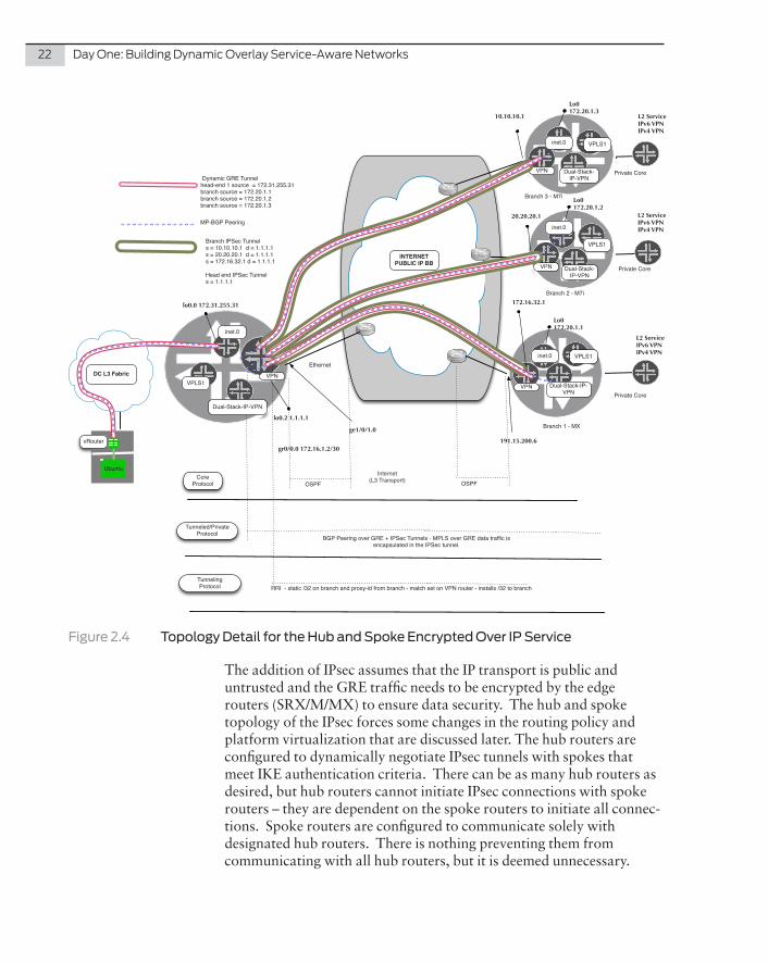
This solution makes use of M/MX/SRX routers in order to support VPLS and IP VPN IPv4 and IPv6 services. Multi-Services (MS) PICs, MS-MIC’s or MS-MPCs are required to support the IPsec tunnels. The previous generation of MS-DPC’s will also work. Figure 2.4 illustrates an overview of the solution.
22 DayOne:BuildingDynamicOverlayService-AwareNetworks
ISP 1
Branch 1 - MX
Ethernet
Private Core
Lo0172.20.1.1
ge1/0/1.0
gr0/0.0 172.16.1.2/30191.15.200.6
VPN
OSPF OSPFInternet
(L3 Transport)Core Protocol
BGP Peering over GRE + IPSec Tunnels - MPLS over GRE data traffic is encapsulated in the IPSec tunnel.
Tunneled/Private Protocol
RRI - static /32 on branch and proxy-id from branch - match set on VPN router - installs /32 to branchTunneling Protocol
Dynamic GRE Tunnelhead-end 1 source = 172.31.255.31branch source = 172.20.1.1branch source = 172.20.1.2branch source = 172.20.1.3
MP-BGP Peering
Branch IPSec Tunnels = 10.10.10.1 d = 1.1.1.1s = 20.20.20.1 d = 1.1.1.1s = 172.16.32.1 d = 1.1.1.1
Head end IPSec Tunnels = 1.1.1.1
L2 ServiceIPv6 VPNIPv4 VPN
Branch 2 - M7i
Private Core
Lo0172.20.1.2
VPN
Private Core
Lo0172.20.1.3
VPN
inet.0
inet.0
INTERNETPUBLIC IP BB
inet.0
inet.0
lo0.0 172.31.255.31
VPN
lo0.2 1.1.1.1
Branch 3 - M7i
10.10.10.1
20.20.20.1
172.16.32.1
VPLS1
VPLS1
VPLS1
L2 ServiceIPv6 VPNIPv4 VPN
L2 ServiceIPv6 VPNIPv4 VPN
VPLS1
vRouter
Ubuntu
DC L3 Fabric
Dual-Stack-IP-VPN
Dual-Stack-IP-VPN
Dual-Stack-IP-VPN
Dual-Stack-IP-VPN
Figure 2.4 Topology Detail for the Hub and Spoke Encrypted Over IP Service
The addition of IPsec assumes that the IP transport is public and untrusted and the GRE traffic needs to be encrypted by the edge routers (SRX/M/MX) to ensure data security. The hub and spoke topology of the IPsec forces some changes in the routing policy and platform virtualization that are discussed later. The hub routers are configured to dynamically negotiate IPsec tunnels with spokes that meet IKE authentication criteria. There can be as many hub routers as desired, but hub routers cannot initiate IPsec connections with spoke routers – they are dependent on the spoke routers to initiate all connec-tions. Spoke routers are configured to communicate solely with designated hub routers. There is nothing preventing them from communicating with all hub routers, but it is deemed unnecessary.
Chapter2:OverlayUseCaseOverviews 23
The IPsec topology is built using Dynamic End Point IPsec (DEP IPsec) at the head-end with reverse route injection (RRI) to advertise the loopback addresses used for encapsulation in the Dynamic GRE process. The phase algorithms chosen are the most secure available in Junos, and, in addition, PKI Certificates are used to authenticate remote sites. It is important to note that although the IPsec endpoints are “public” addresses, the loopback addresses are “private” RFC1918 addresses. This provides an additional level of security as the MP-BGP peers will only be initiated from clients that have already negotiated an IPsec tunnel with the head-end, and additionally the peer addresses will come from a “known” private range defined in the RRI configuration.
Once the underlying IPsec topology is created, and the remote loop-backs are advertised via RRI, MP-BGP is configured to operate directly over it. Next, MP-BGP is configured on all C-PE routers for MPLS VPN signaling. To allow for “zero-touch” on the head end the neigh-bor-allow statement is used to ensure that only the known, private ranges can initiate peering to the head-end. If there are many PE routers in the network, route reflection should be used for manageabil-ity and scalability. In this example, the hub is configured as a route reflector with a next-hop VPN policy to ensure all routes are seen with the next-hop-self (NHS) as the hub for the IP VPN traffic, while for the Layer 2 traffic, all is locally switched at the hub. The most important reason for the NHS design is that if ever another spoke was added for an existing service, or for that matter, as in this example, overlay SDN services in the data center, then there is zero change on the spoke (see Figure 2.5). The new site or data center compute resources are added transparently.
Finally, VPLS and Layer 3 VPN instances are configured on all PE rout-ers in the network for each customer VPN, if required.
In the encrypted solution (Figure 2.5), an Internet-facing routing instance (VPN) is configured to terminate the public interfaces/addressing, allowing increased security as the public network only sees the routes in the public VR. As described earlier in this chapter, the IPsec tunnels terminate in the VPN VR, and a separate IGP process runs in this VR. The use of DEP IPsec and RRI allows an elegant solution and increased security because RRI advertises the /32 host loopback addresses across the IPsec tunnel, which are then used for peering and GRE. The Dynamic GRE adds a differentiating simplicity because the same loopback address is used for GRE encapsulation/de-encapsulation and for MBGP peering MPLS encapsulation/de-encapsulation. In other words, there is no need to configure specific GRE tunnels, or change the protocol configuration from what it would be in a normal PE configuration.
24 DayOne:BuildingDynamicOverlayService-AwareNetworks
inet.0
lo0.0 172.31.255.31
VPN
lo0.2 1.1.1.1
VPLS1
vRouter
Ubuntu
DC L3 Fabric
Dual-Stack-IP-VPN
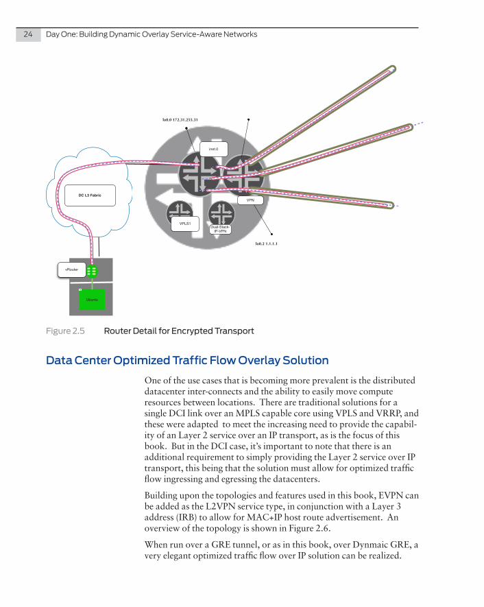
Figure 2.5 Router Detail for Encrypted Transport
Data Center Optimized Traffic Flow Overlay Solution
One of the use cases that is becoming more prevalent is the distributed datacenter inter-connects and the ability to easily move compute resources between locations. There are traditional solutions for a single DCI link over an MPLS capable core using VPLS and VRRP, and these were adapted to meet the increasing need to provide the capabil-ity of an Layer 2 service over an IP transport, as is the focus of this book. But in the DCI case, it’s important to note that there is an additional requirement to simply providing the Layer 2 service over IP transport, this being that the solution must allow for optimized traffic flow ingressing and egressing the datacenters.
Building upon the topologies and features used in this book, EVPN can be added as the L2VPN service type, in conjunction with a Layer 3 address (IRB) to allow for MAC+IP host route advertisement. An overview of the topology is shown in Figure 2.6.
When run over a GRE tunnel, or as in this book, over Dynmaic GRE, a very elegant optimized traffic flow over IP solution can be realized.

Chapter2:OverlayUseCaseOverviews 25
The competitive Cisco solution is to pair LISP with OTV to provide “over IP” Layer 2 Datacenter Interconnect (DCI), and chapter 3 details how Cisco OTV is used to provide the Layer 2 transport and how LISP provides the optimized ingress routing.
The benefits of the Juniper approach are important:
� The control plane is all BGP.
� It seamlessly integrates with existing virtualization techniques (other IP-VPNs, VPLS, CCC).
� EVPN provides Layer 2 MAC mobility, GW Egress Optimiza-tion, and Layer 3 ARP Snooping for Layer 3 route injection.
t
Figure 2.6 DCI VM Moves with Ingress and Egress Traffic Optimization
26 DayOne:BuildingDynamicOverlayService-AwareNetworks
In this instance, EVPN is configured as enabled on a virtual switch in this design, with a single bridge domain configured, in this case, whereas in larger data center environments there would most likely be multiple Bridge Domains (BDs) in a virtual switch. It all depends on the scale requirements, the security requirements, and the flexibility required per customer/tenant in the data center.
MORE? For further information on virtual switches, bridge domains, their relationship to each other, and their configuration with routing instances refer to the following: for documentation see http://www.juniper.net/techpubs/en_US/junos13.3/topics/concept/layer-2-services-virtual-switch-overview.html, or http://www.juniper.net/techpubs/en_US/junos13.3/topics/task/configuration/layer-2-services-routing-instance-minimum-configuration-virtual-switch.html, and, http://www.juniper.net/techpubs/en_US/junos13.3/topics/task/configuration/layer-2-services-virtual-switch-configuring.html; or read Chapter 2 of Juniper MX Series by Doug Hanks and Harry Reynolds at http://www.juniper.net/us/en/training/jnbooks/mx-series.html.
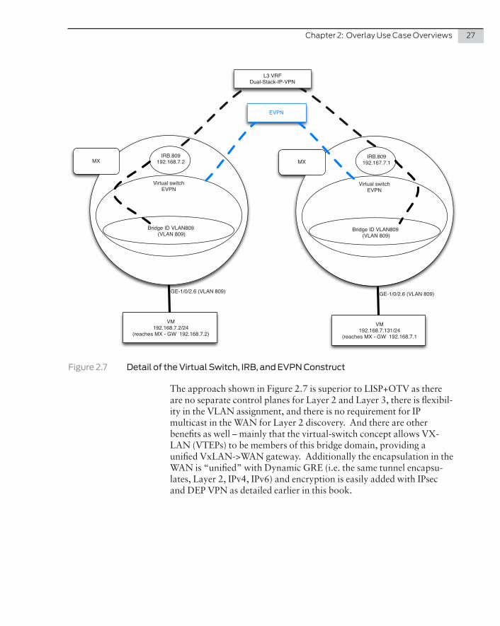
Using the virtual switch and EVPN provides the ultimate flexibility in the edge with the following benefits and as shown in Figure 2.7:
� One can “normalize” VLANs in which an IFL is a member of one VLAN (802.1q tag configured) but the bridge domain has another VLAN-ID configured. This gives the data center admin-istrator the flexibility of assigning any access layer VLAN (or VLANs) to the customer and then normalizing them to the bridge domain VLAN-ID.
� The data center administrator can assign multiple bridge do-mains to one EVPN instance (EVI), thus easily scaling the data center interconnect.
� Each bridge domain can be assigned an IRB to make it Layer 3-aware. If an IRB is configured, EVPN snoops the ARP and installs the /32 host route in the configured Layer 3 IP VPN. If no IRB is associated with the bridge domain the solution stays at Layer 2.
� This automatic Layer 3 route installation enables the remote clients to route directly to the correct data center on a /32 host granularity. In essence the Layer 3 is following the Layer 2.
Chapter2:OverlayUseCaseOverviews 27
MX
Virtual switchEVPN
VM192.168.7.2/24
(reaches MX - GW 192.168.7.2)
Bridge ID VLAN809 (VLAN 809)
GE-1/0/2.6 (VLAN 809)
IRB.809192.168.7.2 MX
Virtual switchEVPN
Bridge ID VLAN809 (VLAN 809)
IRB.809192.167.7.1
EVPN
VM192.168.7.131/24
(reaches MX - GW 192.168.7.1
GE-1/0/2.6 (VLAN 809)
L3 VRF Dual-Stack-IP-VPN
Figure 2.7 Detail of the Virtual Switch, IRB, and EVPN Construct
The approach shown in Figure 2.7 is superior to LISP+OTV as there are no separate control planes for Layer 2 and Layer 3, there is flexibil-ity in the VLAN assignment, and there is no requirement for IP multicast in the WAN for Layer 2 discovery. And there are other benefits as well – mainly that the virtual-switch concept allows VX-LAN (VTEPs) to be members of this bridge domain, providing a unified VxLAN->WAN gateway. Additionally the encapsulation in the WAN is “unified” with Dynamic GRE (i.e. the same tunnel encapsu-lates, Layer 2, IPv4, IPv6) and encryption is easily added with IPsec and DEP VPN as detailed earlier in this book.

28 DayOne:BuildingDynamicOverlayService-AwareNetworks
There are three main use cases where LISP is positioned, sometimes with other technologies, as LISP is a Layer 3-only solution. The use case is always over an IP core – that is, there is no MPLS label awareness in the core, as LISP is an IP-in-IP tunneling/mapping solution, while MPLS is natively an IP (or MAC) in Label solution. In these use cases, however, the label stack is a VPN Label, plus GRE/IP header.
There is an abundance of information on LISP and its operation, but at a high level LISP is a routing architecture that separates the device identity, or endpoint identifier (EID), from its location, or routing locator (RLOC), into two different numbering spaces. In other words, it decouples an endpoint’s IP address and its location. It does this by tunneling the original IP packet in a new IP header – this new header being the Ingress and Egress Tunneling routers (ITR’s and ETR’s). It is a very similar approach to the Dynamic GRE architec-ture covered in this book. One difference is that the tunnel header information is requested on demand, and caches the responses from the mapping server (and the ETR that responds with more tunneling information). Think of this as working exactly like DNS. The difference with BGP is that it is a distributed database, of course.
MORE? Additional information on LISP can be found at: http://www.cisco.com/c/en/us/products/ios-nx-os-software/locator-id-separation-pro-tocol-lisp/index.html.
Now, which one is better? LISP advocates claim the pull and request approach is better, as less state is required on the ITR/ETRs. Is this actually true in a real network? Once the network has run for some time the mapping cache on the routers is populated with more and more remote network to ETR mappings, much like the label table on the PEs. Additionally, there are many policies that can be applied to BGP and VPN route advertisements to reduce this state on BGP PEs.
Chapter 3
Comparison with Cisco LISP Use Cases
30 DayOne:BuildingDynamicOverlayService-AwareNetworks
The most obvious disadvantage is that LISP is a completely separate control plane from the Layer 2 service. By using BGP, one has the same control plane for all traffic, Layer 2, Layer 3 VPN, and “plain-vanilla” IP traffic.
There are other disadvantages with LISP, namely:
� The ITR/ETR configuration is very static – one defines, effective-ly with an ACL, which networks need to be tunneled.
� The tunneling adds more overhead than MPLS or GRE tunnel-ing.
� No Stateful firewall support for the LISP protocol.
� No Layer 2 support.
� No fragmentation/reassembly support.
DCI with VM Mobility
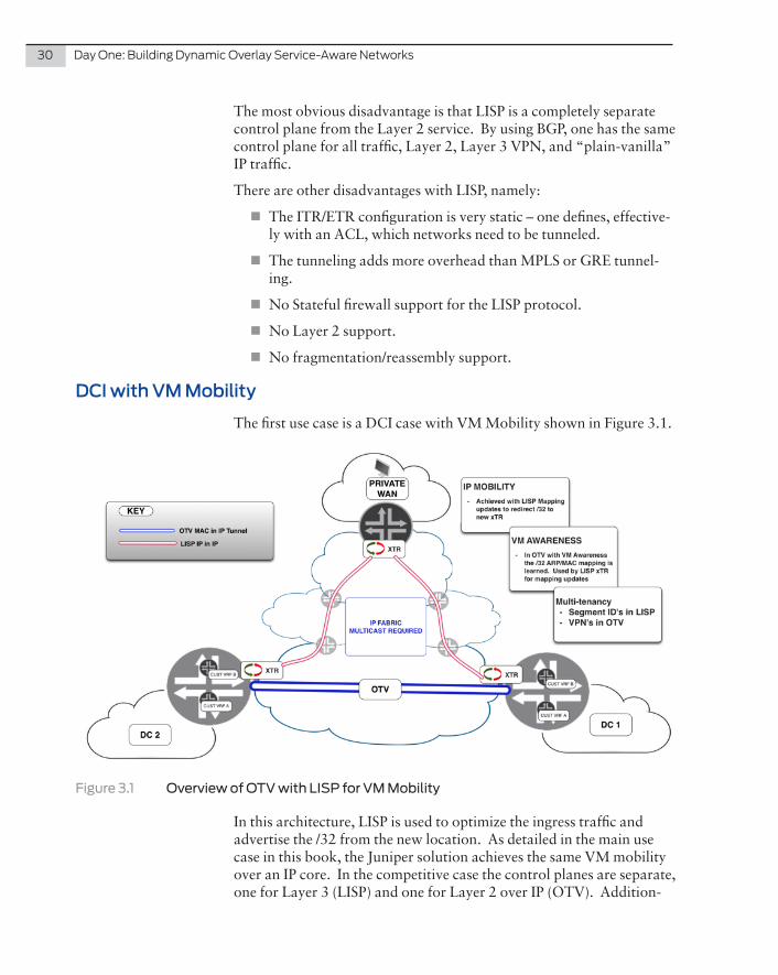
The first use case is a DCI case with VM Mobility shown in Figure 3.1.
Figure 3.1 Overview of OTV with LISP for VM Mobility
In this architecture, LISP is used to optimize the ingress traffic and advertise the /32 from the new location. As detailed in the main use case in this book, the Juniper solution achieves the same VM mobility over an IP core. In the competitive case the control planes are separate, one for Layer 3 (LISP) and one for Layer 2 over IP (OTV). Addition-
Chapter3:ComparisonwithCiscoLISPUseCases 31
ally the forwarding plane, or data plane, is separate, being MAC in IP using the OTV forwarding infrastructure and IP in IP LISP overlay infrastructure, whereas in the Juniper solution the forwarding is also unified on the Dynamic GRE interface. Support of the competitive solution is also restricted to certain platforms. Another important differentiator for the Juniper solution is equally applicable if the DCI (WAN) is MPLS enabled – the Juniper platforms will automatically choose the LSP path if available.
Figure 3.1 illustrates at a high level the Cisco solution where the LAN extension is provided by OTV, there are customer VPNs being trans-ported using OTV, and likewise LISP with segment-IDs to identify the customers in the LISP-world, is used to provide the Layer 3 ingress traffic optimization. Fabric-Path, FEX, or over-IP VXLAN is used within the DC.
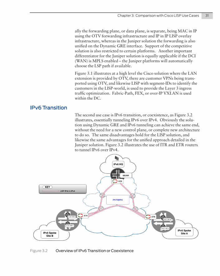
IPv6 TransitionThe second use case is IPv6 transition, or coexistence, as Figure 3.2 illustrates, essentially tunneling IPv6 over IPv4. Obviously the solu-tion using Dynamic GRE and IPv6 tunneling can achieve the same end, without the need for a new control plane, or complete new architecture to do so. The same disadvantages hold for the LISP solution, and likewise the same advantages for the unified approach detailed in the Juniper solution. Figure 3.2 illustrates the use of ITR and ETR routers to tunnel IPv6 over IPv4.
Figure 3.2 Overview of IPv6 Transition or Coexistence

32 DayOne:BuildingDynamicOverlayService-AwareNetworks
Multi-Tenancy (VPNs) Over LISP
The third case is where LISP is positioned as a method to transport VPNs (VRFs) over an IP (or Layer 2) core. The Juniper solution was designed to provide just this architecture at scale and uses the same architectural approach as one would in a standard VPN deployment. Again, the same benefits hold for the Juniper approach, versus the same drawbacks of implementing a new overlay architecture and control plane, as would have to be done in the LISP approach.
Figure 3.3 Overview of Multitenancy with LISP
NOTE A final note on one use case where LISP is combined with GET VPN for security: in this design LISP (an IP Packet) is matched and encrypt-ed using GET VPN for an any-to-any secure overlay. The design in this book is hub and spoke, with spoke-spoke via the hub, thus achieving the same secure overlay albeit with a different overlay topology. With the addition of GET VPN on the MX in Junos 14.1, the same “true” any-to-any secure overlay can be realized. In the Juniper solution the match will be on GRE traffic (or the loopback peering address range) and all traffic will be encrypted and at the same time maintain the any-to-any direct forwarding path across the IP core.
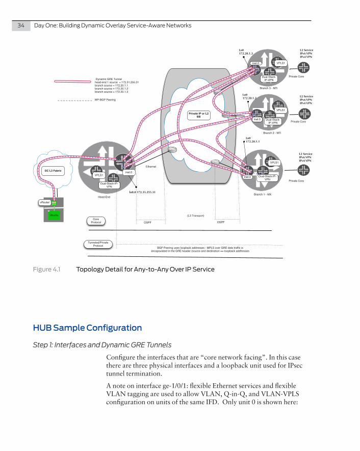
This chapter sets out the configuration details for the any-to-any overlay solution. For your convenience, Figure 2.2 is repeated here as Figure 4.1. Also, notes are placed within the configurations and appear as boldface type.
This section is formatted such that an engineer or architect can follow the steps to configure the components in a logical manner and it builds the topology in a step-by-step manner per-device as one would build out the network. The detail in the diagrams and the detailed configu-ration steps will allow a simple replication in a lab, or even a replica-tion to build out at scale.
All salient parts of the configuration are detailed, the only parts that are missing are the authentication and network management elements, such as AAA, and SNMP.
In your lab you should use the MX Series, SRX series, and M Series, all running Junos 11.4 and later. (In Chapter 6, the MX Series will need to run Junos 14.1 or later.)
Chapter 4
Implementation Steps: Any-to-Any Overlay Solution
34 DayOne:BuildingDynamicOverlayService-AwareNetworks
Head-EndBranch 1 - MX
Ethernet
Private Core
Lo0172.20.1.1
OSPF OSPF
(L3 Transport)Core
Protocol
BGP Peering uses loopback addresses - MPLS over GRE data traffic is encapsulated in the GRE header (source and destination == loopback addfresses
Tunneled/Private Protocol
Dynamic GRE Tunnelhead-end 1 source = 172.31.255.31branch source = 172.20.1.1branch source = 172.20.1.2branch source = 172.20.1.3
MP-BGP Peering
L2 ServiceIPv6 VPNIPv4 VPN
Branch 2 - M7i
Private Core
Lo0172.20.1.2
Private Core
Lo0172.20.1.3
inet.0
inet.0
Private IP or L2 BB
inet.0
lo0.0 172.31.255.31
Branch 3 - M7i
VPLS1
VPLS1
VPLS1
L2 ServiceIPv6 VPNIPv4 VPN
L2 ServiceIPv6 VPNIPv4 VPN
VPLS1
vRouter
Ubuntu
DC L3 Fabric inet.0Dual-Stack-IP-
VPN Dual-Stack-IP-
VPN
Dual-Stack-IP-VPN
Dual-Stack-IP-VPN
Figure 4.1 Topology Detail for Any-to-Any Over IP Service
HUB Sample Configuration
Step 1: Interfaces and Dynamic GRE Tunnels
Configure the interfaces that are “core network facing”. In this case there are three physical interfaces and a loopback unit used for IPsec tunnel termination.
A note on interface ge-1/0/1: flexible Ethernet services and flexible VLAN tagging are used to allow VLAN, Q-in-Q, and VLAN-VPLS configuration on units of the same IFD. Only unit 0 is shown here:
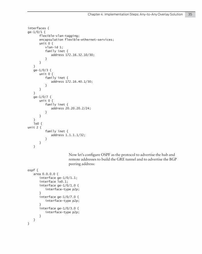
Chapter4:ImplementationSteps:Any-to-AnyOverlaySolution 35
interfaces {ge-1/0/1 { flexible-vlan-tagging; encapsulation flexible-ethernet-services; unit 0 { vlan-id 1; family inet { address 172.16.32.10/30; } } } ge-1/0/3 { unit 0 { family inet { address 172.16.40.1/30; } } } ge-1/0/7 { unit 0 { family inet { address 20.20.20.2/24; } } } lo0 {unit 2 { family inet { address 1.1.1.1/32; } } }
Now let’s configure OSPF as the protocol to advertise the hub and remote addresses to build the GRE tunnel and to advertise the BGP peering address:
ospf { area 0.0.0.0 { interface ge-1/0/1.1; interface lo0.1; interface ge-1/0/1.0 { interface-type p2p; } interface ge-1/0/7.0 { interface-type p2p; } interface ge-1/0/3.0 { interface-type p2p; } }}
36 DayOne:BuildingDynamicOverlayService-AwareNetworks
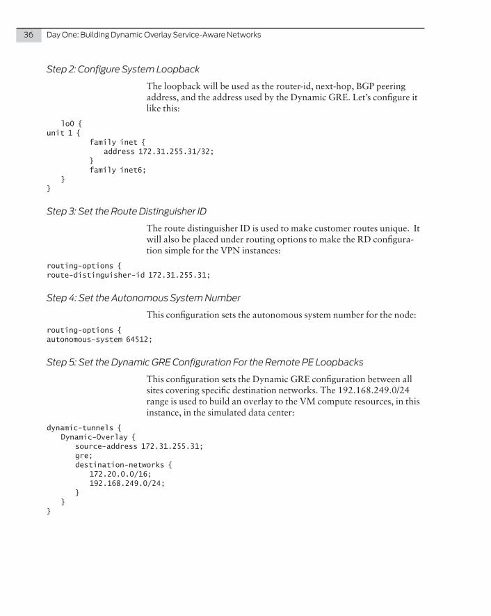
Step 2: Configure System Loopback
The loopback will be used as the router-id, next-hop, BGP peering address, and the address used by the Dynamic GRE. Let’s configure it like this:
lo0 {unit 1 { family inet { address 172.31.255.31/32; } family inet6; }}
Step 3: Set the Route Distinguisher ID
The route distinguisher ID is used to make customer routes unique. It will also be placed under routing options to make the RD configura-tion simple for the VPN instances:
routing-options {route-distinguisher-id 172.31.255.31;
Step 4: Set the Autonomous System Number
This configuration sets the autonomous system number for the node:
routing-options {autonomous-system 64512;
Step 5: Set the Dynamic GRE Configuration For the Remote PE Loopbacks
This configuration sets the Dynamic GRE configuration between all sites covering specific destination networks. The 192.168.249.0/24 range is used to build an overlay to the VM compute resources, in this instance, in the simulated data center:
dynamic-tunnels { Dynamic-Overlay { source-address 172.31.255.31; gre; destination-networks { 172.20.0.0/16; 192.168.249.0/24; } }}
Chapter4:ImplementationSteps:Any-to-AnyOverlaySolution 37
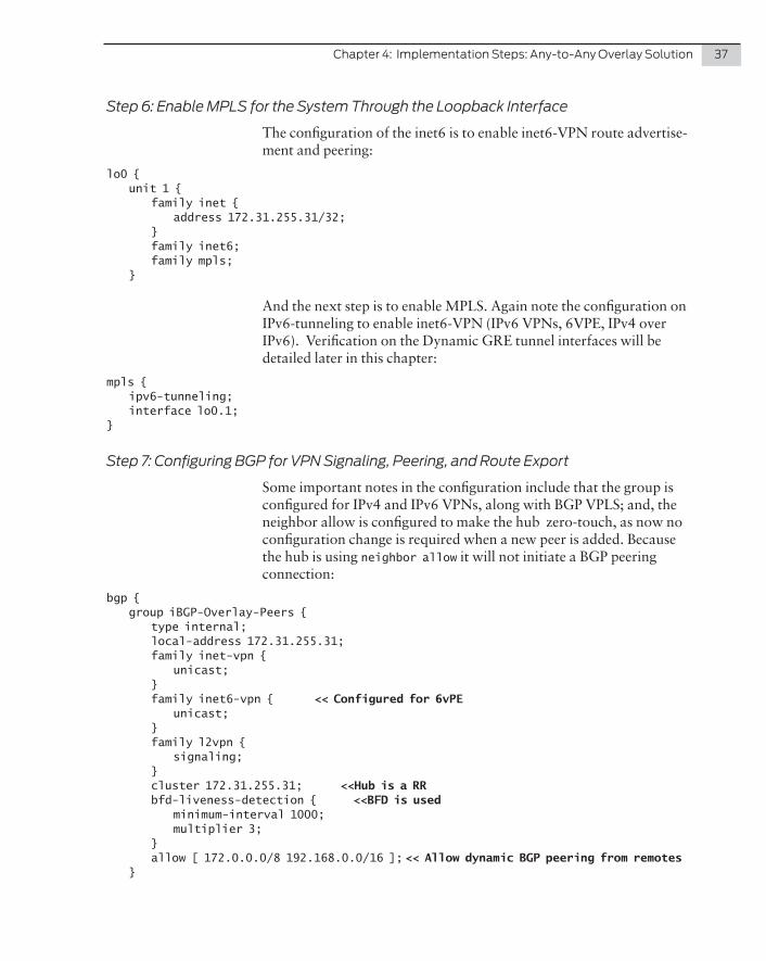
Step 6: Enable MPLS for the System Through the Loopback Interface
The configuration of the inet6 is to enable inet6-VPN route advertise-ment and peering:
lo0 { unit 1 { family inet { address 172.31.255.31/32; } family inet6; family mpls; }
And the next step is to enable MPLS. Again note the configuration on IPv6-tunneling to enable inet6-VPN (IPv6 VPNs, 6VPE, IPv4 over IPv6). Verification on the Dynamic GRE tunnel interfaces will be detailed later in this chapter:
mpls { ipv6-tunneling; interface lo0.1;}
Step 7: Configuring BGP for VPN Signaling, Peering, and Route Export
Some important notes in the configuration include that the group is configured for IPv4 and IPv6 VPNs, along with BGP VPLS; and, the neighbor allow is configured to make the hub zero-touch, as now no configuration change is required when a new peer is added. Because the hub is using neighbor allow it will not initiate a BGP peering connection:
bgp { group iBGP-Overlay-Peers { type internal; local-address 172.31.255.31; family inet-vpn { unicast; } family inet6-vpn { << Configured for 6vPE unicast; } family l2vpn { signaling; } cluster 172.31.255.31; <<Hub is a RR bfd-liveness-detection { <<BFD is used minimum-interval 1000; multiplier 3; } allow [ 172.0.0.0/8 192.168.0.0/16 ]; << Allow dynamic BGP peering from remotes }
38 DayOne:BuildingDynamicOverlayService-AwareNetworks
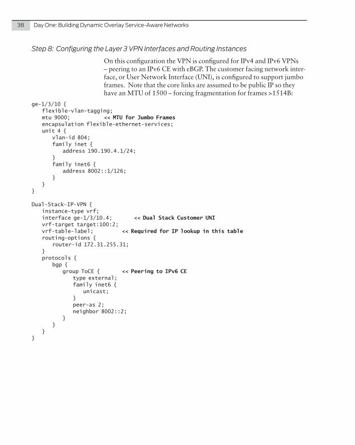
Step 8: Configuring the Layer 3 VPN Interfaces and Routing Instances
On this configuration the VPN is configured for IPv4 and IPv6 VPNs – peering to an IPv6 CE with eBGP. The customer facing network inter-face, or User Network Interface (UNI), is configured to support jumbo frames. Note that the core links are assumed to be public IP so they have an MTU of 1500 – forcing fragmentation for frames >1514B:
ge-1/3/10 { flexible-vlan-tagging; mtu 9000; << MTU for Jumbo Frames encapsulation flexible-ethernet-services; unit 4 { vlan-id 804; family inet { address 190.190.4.1/24; } family inet6 { address 8002::1/126; } }}
Dual-Stack-IP-VPN { instance-type vrf; interface ge-1/3/10.4; << Dual Stack Customer UNI vrf-target target:100:2; vrf-table-label; << Required for IP lookup in this table routing-options { router-id 172.31.255.31; } protocols { bgp { group ToCE { << Peering to IPv6 CE type external; family inet6 { unicast; } peer-as 2; neighbor 8002::2; } } }}
Chapter4:ImplementationSteps:Any-to-AnyOverlaySolution 39
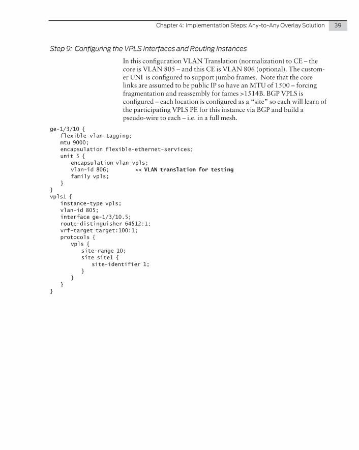
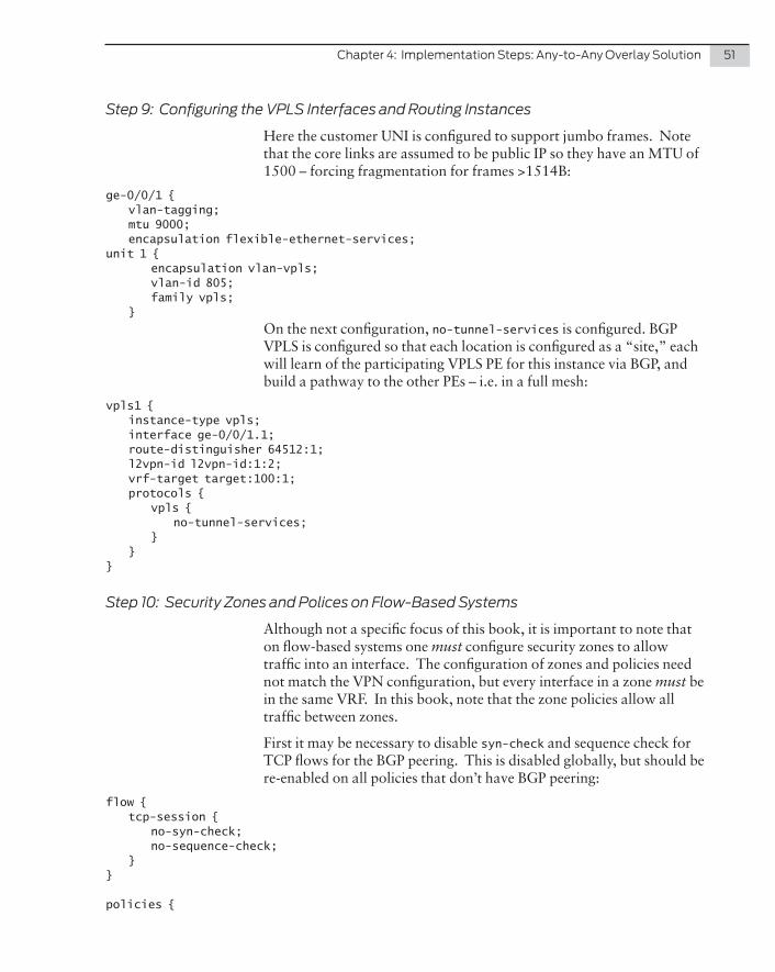
Step 9: Configuring the VPLS Interfaces and Routing Instances
In this configuration VLAN Translation (normalization) to CE – the core is VLAN 805 – and this CE is VLAN 806 (optional). The custom-er UNI is configured to support jumbo frames. Note that the core links are assumed to be public IP so have an MTU of 1500 – forcing fragmentation and reassembly for fames >1514B. BGP VPLS is configured – each location is configured as a “site” so each will learn of the participating VPLS PE for this instance via BGP and build a pseudo-wire to each – i.e. in a full mesh.
ge-1/3/10 { flexible-vlan-tagging; mtu 9000; encapsulation flexible-ethernet-services; unit 5 { encapsulation vlan-vpls; vlan-id 806; << VLAN translation for testing family vpls; }}vpls1 { instance-type vpls; vlan-id 805; interface ge-1/3/10.5; route-distinguisher 64512:1; vrf-target target:100:1; protocols { vpls { site-range 10; site site1 { site-identifier 1; } } }}
40 DayOne:BuildingDynamicOverlayService-AwareNetworks
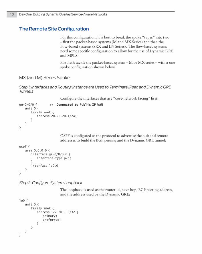
The Remote Site Configuration
For this configuration, it is best to break the spoke “types” into two – first the packet-based systems (M and MX Series) and then the flow-based systems (SRX and LN Series). The flow-based systems need some specific configuration to allow for the use of Dynamic GRE and MPLS.
First let’s tackle the packet-based system – M or MX series – with a one spoke configuration shown below.
MX(andM)SeriesSpoke
Step 1: Interfaces and Routing Instance are Used to Terminate IPsec and Dynamic GRE Tunnels
Configure the interfaces that are “core-network facing” first:
ge-0/0/0 { >> Connected to Public IP WAN unit 0 { family inet { address 20.20.20.1/24; } }}
OSPF is configured as the protocol to advertise the hub and remote addresses to build the BGP peering and the Dynamic GRE tunnel:
ospf { area 0.0.0.0 { interface ge-0/0/0.0 { interface-type p2p; } interface lo0.0; }}
Step 2: Configure System Loopback
The loopback is used as the router-id, next-hop, BGP peering address, and the address used by the Dynamic GRE:
lo0 { unit 0 { family inet { address 172.20.1.3/32 { primary; preferred; } } }}
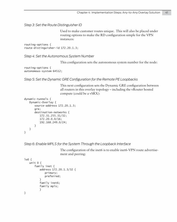
Chapter4:ImplementationSteps:Any-to-AnyOverlaySolution 41
Step 3: Set the Route Distinguisher ID
Used to make customer routes unique. This will also be placed under routing options to make the RD configuration simple for the VPN instances:
routing-options {route-distinguisher-id 172.20.1.3;
Step 4: Set the Autonomous System Number
This configuration sets the autonomous system number for the node:
routing-options {autonomous-system 64512;
Step 5: Set the Dynamic GRE Configuration for the Remote PE Loopbacks
This next configuration sets the Dynamic GRE configuration between all routers in this overlay topology – including the vRouter hosted compute (could be a vSRX):
dynamic-tunnels { Dynamic-Overlay { source-address 172.20.1.3; gre; destination-networks { 172.31.255.31/32; 172.20.0.0/16; 192.168.249.0/24; } }}
Step 6: Enable MPLS for the System Through the Loopback Interface
The configuration of the inet6 is to enable inet6-VPN route advertise-ment and peering:
lo0 { unit 0 { family inet { address 172.20.1.3/32 { primary; preferred; } family inet6; family mpls; }}
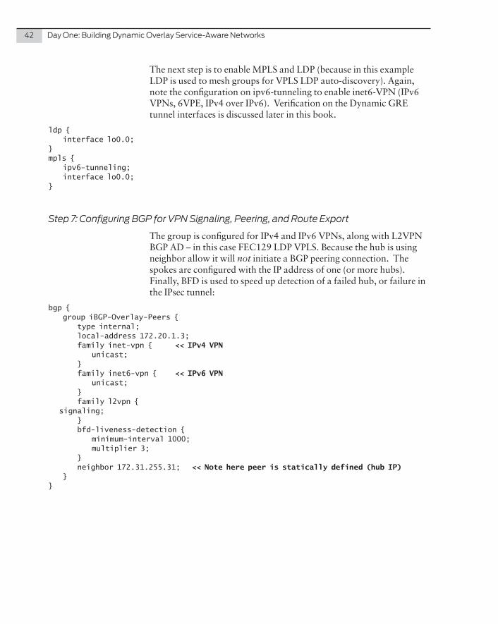
42 DayOne:BuildingDynamicOverlayService-AwareNetworks
The next step is to enable MPLS and LDP (because in this example LDP is used to mesh groups for VPLS LDP auto-discovery). Again, note the configuration on ipv6-tunneling to enable inet6-VPN (IPv6 VPNs, 6VPE, IPv4 over IPv6). Verification on the Dynamic GRE tunnel interfaces is discussed later in this book.
ldp { interface lo0.0;}mpls { ipv6-tunneling; interface lo0.0;}
Step 7: Configuring BGP for VPN Signaling, Peering, and Route Export
The group is configured for IPv4 and IPv6 VPNs, along with L2VPN BGP AD – in this case FEC129 LDP VPLS. Because the hub is using neighbor allow it will not initiate a BGP peering connection. The spokes are configured with the IP address of one (or more hubs). Finally, BFD is used to speed up detection of a failed hub, or failure in the IPsec tunnel:
bgp { group iBGP-Overlay-Peers { type internal; local-address 172.20.1.3; family inet-vpn { << IPv4 VPN unicast; } family inet6-vpn { << IPv6 VPN unicast; } family l2vpn { signaling; } bfd-liveness-detection { minimum-interval 1000; multiplier 3; } neighbor 172.31.255.31; << Note here peer is statically defined (hub IP) }}
Chapter4:ImplementationSteps:Any-to-AnyOverlaySolution 43
Step 8: Configuring the Layer 3 VPN Interfaces and Routing Instances
The VPN is configured for IPv4 and IPv6 VPNs – peering to an IPv6 CE with eBGP. The customer UNI is configured to support jumbo frames. Note that the core links are assumed to be public IP, so they have an MTU of 1500 – forcing fragmentation for fames >1514B. In the case of the M series, where VRF-table-label is not available with Dynamic GRE, you need a VT unit to loop traffic for the lookup, as cited:
ge-0/0/3 { flexible-vlan-tagging; mtu 9000; encapsulation flexible-ethernet-services; unit 4 { vlan-id 823; family inet { address 190.192.4.1/24; } family inet6 { address 8001::1/126; } }}vt-1/2/0 { << Configure vt unit unit 1 { family inet; family inet6; }}
Dual-Stack-IP-VPN { instance-type vrf; interface ge-0/0/3.4; interface vt-1/2/0.1; << vt interface IS required here to allow IP lookup vrf-target target:100:2; routing-options { router-id 172.20.1.3; } protocols { bgp { group ToCE { << Configure IPv6 CE type external; family inet6 { unicast; } peer-as 1; neighbor 8001::2; } } }}
44 DayOne:BuildingDynamicOverlayService-AwareNetworks
Step 9: Configuring the VPLS Interfaces and Routing Instances
VLAN Translation (normalization) to CE – core is VLAN 805 – this CE is VLAN808 (optional). The Customer UNI is configured to support jumbo frames. Note that the core links are assumed to be public IP so they have an MTU of 1500 – forcing fragmentation for fames >1514B. BGP VPLS is configured - each location is configured as a “site,” each will learn of the participating VPLS PE for this instance via BGP, and build a pseudo-wire to each – therefore, in a full mesh:
ge-0/0/3 { flexible-vlan-tagging; mtu 9000; encapsulation flexible-ethernet-services; unit 5 { encapsulation vlan-vpls; vlan-id 808; input-vlan-map { << Note vlan-map swap used: s-vlan (VPLS) 805, c-vlan 808 swap; vlan-id 805; } output-vlan-map swap; family vpls; }}
vpls1 { instance-type vpls; interface ge-0/0/3.5; route-distinguisher 64512:4; vrf-target target:100:1; protocols { vpls { site-range 10; site site4 { site-identifier 4; } } }}
Chapter4:ImplementationSteps:Any-to-AnyOverlaySolution 45
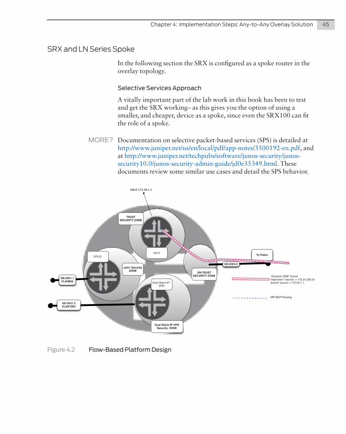
SRXandLNSeriesSpoke
In the following section the SRX is configured as a spoke router in the overlay topology.
Selective Services Approach
A vitally important part of the lab work in this book has been to test and get the SRX working– as this gives you the option of using a smaller, and cheaper, device as a spoke, since even the SRX100 can fit the role of a spoke.
MORE? Documentation on selective packet-based services (SPS) is detailed at http://www.juniper.net/us/en/local/pdf/app-notes/3500192-en.pdf, and at http://www.juniper.net/techpubs/software/junos-security/junos-security10.0/junos-security-admin-guide/jd0e35349.html. These documents review some similar use cases and detail the SPS behavior.
inet.0
lo0.0 172.20.1.1
VPLS1
Dual-Stack-IP-VPN
To Peers
GE-0/0/3.0
GE-0/0/1.1VLAN805
GE-0/0/1.2VLAN1004
TRUST SECURITY ZONE
UN-TRUST SECURITY ZONE Dynamic GRE Tunnel
head-end 1 source = 172.31.255.31branch source = 172.20.1.1
MP-BGP Peering
Dual-Stack-IP-VPN Security ZONE
vpls1 Security ZONE
Figure 4.2 Flow-Based Platform Design
46 DayOne:BuildingDynamicOverlayService-AwareNetworks
Step 1: Configure Interfaces Used to Terminate Dynamic GRE Tunnels
Let’s first configure the interfaces:
ge-0/0/3 { unit 0 { family inet { address 172.16.32.1/30; } }
The secret sauce is in the packet-mode filter, which forces all traffic matching this filter to be treated as packet-based. This is applied on every interface that requires traffic to be treated as packet based (including CE-facing IFLs):
ge-0/0/3 { << Core facing Interface unit 0 { family inet { filter { input packet-mode; << Force IPv4 into packet mode } address 172.16.32.1/30; } family inet6; }}ge-0/0/1 { << CE facing Interface vlan-tagging; mtu 9000; << Jumbo frame support encapsulation flexible-ethernet-services; unit 0 { proxy-arp unrestricted; vlan-id 1003; family inet { filter { input packet-mode; << Force IPv4 into packet mode } address 8.8.8.1/24; } family mpls; } unit 2 { << CE facing Interface vlan-id 1004; family inet { filter { input packet-mode; << Force IPv4 into packet mode } address 190.193.1.1/24; }
Chapter4:ImplementationSteps:Any-to-AnyOverlaySolution 47
family inet6 { address 9001::1/126; } }}
firewall { family inet { filter packet-mode { interface-specific; term all { then { count pkts; packet-mode; accept; } } } }}
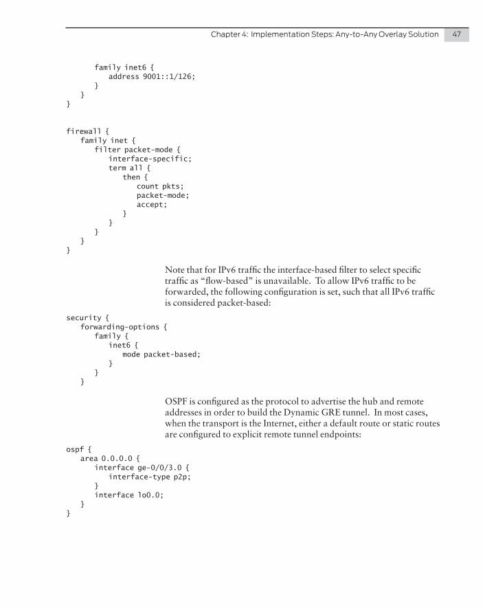
Note that for IPv6 traffic the interface-based filter to select specific traffic as “flow-based” is unavailable. To allow IPv6 traffic to be forwarded, the following configuration is set, such that all IPv6 traffic is considered packet-based:
security { forwarding-options { family { inet6 { mode packet-based; } } }
OSPF is configured as the protocol to advertise the hub and remote addresses in order to build the Dynamic GRE tunnel. In most cases, when the transport is the Internet, either a default route or static routes are configured to explicit remote tunnel endpoints:
ospf { area 0.0.0.0 { interface ge-0/0/3.0 { interface-type p2p; } interface lo0.0; }}
48 DayOne:BuildingDynamicOverlayService-AwareNetworks
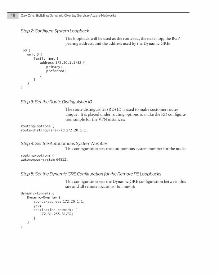
Step 2: Configure System Loopback
The loopback will be used as the router-id, the next-hop, the BGP peering address, and the address used by the Dynamic GRE:
lo0 { unit 0 { family inet { address 172.20.1.1/32 { primary; preferred; } } }}
Step 3: Set the Route Distinguisher ID
The route distinguisher (RD) ID is used to make customer routes unique. It is placed under routing options to make the RD configura-tion simple for the VPN instances:
routing-options {route-distinguisher-id 172.20.1.1;
Step 4: Set the Autonomous System NumberThis configuration sets the autonomous system number for the node:
routing-options {autonomous-system 64512;
Step 5: Set the Dynamic GRE Configuration for the Remote PE Loopbacks
This configuration sets the Dynamic GRE configuration between this site and all remote locations (full mesh):
dynamic-tunnels { Dynamic-Overlay { source-address 172.20.1.1; gre; destination-networks { 172.31.255.31/32; } }}
Chapter4:ImplementationSteps:Any-to-AnyOverlaySolution 49
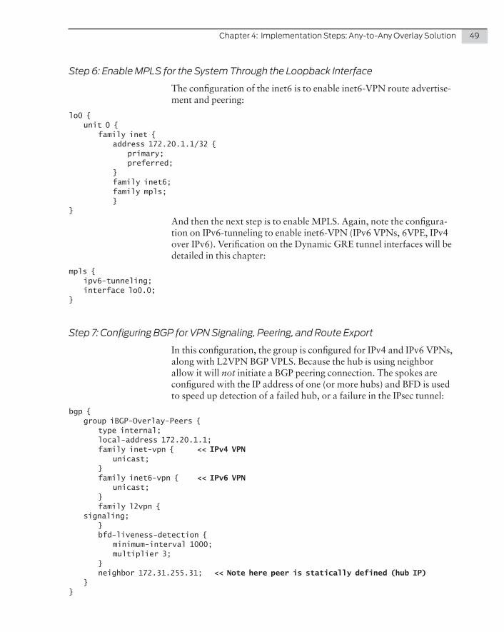
Step 6: Enable MPLS for the System Through the Loopback Interface
The configuration of the inet6 is to enable inet6-VPN route advertise-ment and peering:
lo0 { unit 0 { family inet { address 172.20.1.1/32 { primary; preferred; } family inet6; family mpls; }}
And then the next step is to enable MPLS. Again, note the configura-tion on IPv6-tunneling to enable inet6-VPN (IPv6 VPNs, 6VPE, IPv4 over IPv6). Verification on the Dynamic GRE tunnel interfaces will be detailed in this chapter:
mpls { ipv6-tunneling; interface lo0.0;}
Step 7: Configuring BGP for VPN Signaling, Peering, and Route Export
In this configuration, the group is configured for IPv4 and IPv6 VPNs, along with L2VPN BGP VPLS. Because the hub is using neighbor allow it will not initiate a BGP peering connection. The spokes are configured with the IP address of one (or more hubs) and BFD is used to speed up detection of a failed hub, or a failure in the IPsec tunnel:
bgp { group iBGP-Overlay-Peers { type internal; local-address 172.20.1.1; family inet-vpn { << IPv4 VPN unicast; } family inet6-vpn { << IPv6 VPN unicast; } family l2vpn { signaling; } bfd-liveness-detection { minimum-interval 1000; multiplier 3; } neighbor 172.31.255.31; << Note here peer is statically defined (hub IP) }}
50 DayOne:BuildingDynamicOverlayService-AwareNetworks
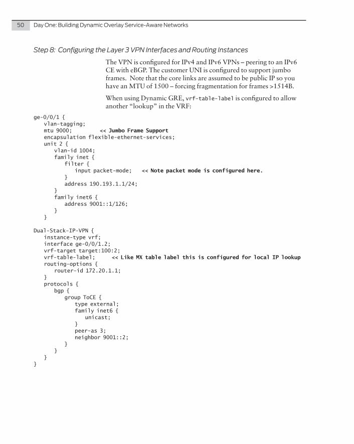
Step 8: Configuring the Layer 3 VPN Interfaces and Routing Instances
The VPN is configured for IPv4 and IPv6 VPNs – peering to an IPv6 CE with eBGP. The customer UNI is configured to support jumbo frames. Note that the core links are assumed to be public IP so you have an MTU of 1500 – forcing fragmentation for frames >1514B.
When using Dynamic GRE, vrf-table-label is configured to allow another “lookup” in the VRF:
ge-0/0/1 { vlan-tagging; mtu 9000; << Jumbo Frame Support encapsulation flexible-ethernet-services; unit 2 { vlan-id 1004; family inet { filter { input packet-mode; << Note packet mode is configured here. } address 190.193.1.1/24; } family inet6 { address 9001::1/126; } }
Dual-Stack-IP-VPN { instance-type vrf; interface ge-0/0/1.2; vrf-target target:100:2; vrf-table-label; << Like MX table label this is configured for local IP lookup routing-options { router-id 172.20.1.1; } protocols { bgp { group ToCE { type external; family inet6 { unicast; } peer-as 3; neighbor 9001::2; } } }}
Chapter4:ImplementationSteps:Any-to-AnyOverlaySolution 51
Step 9: Configuring the VPLS Interfaces and Routing Instances
Here the customer UNI is configured to support jumbo frames. Note that the core links are assumed to be public IP so they have an MTU of 1500 – forcing fragmentation for frames >1514B:
ge-0/0/1 { vlan-tagging; mtu 9000; encapsulation flexible-ethernet-services;unit 1 { encapsulation vlan-vpls; vlan-id 805; family vpls; }
On the next configuration, no-tunnel-services is configured. BGP VPLS is configured so that each location is configured as a “site,” each will learn of the participating VPLS PE for this instance via BGP, and build a pathway to the other PEs – i.e. in a full mesh:
vpls1 { instance-type vpls; interface ge-0/0/1.1; route-distinguisher 64512:1; l2vpn-id l2vpn-id:1:2; vrf-target target:100:1; protocols { vpls { no-tunnel-services; } }}
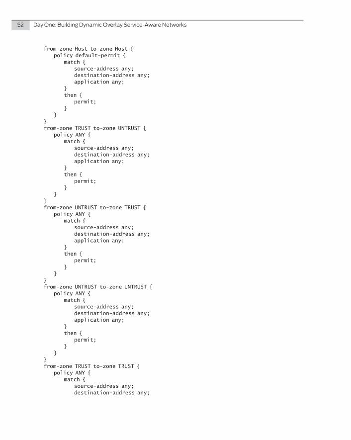
Step 10: Security Zones and Polices on Flow-Based Systems
Although not a specific focus of this book, it is important to note that on flow-based systems one must configure security zones to allow traffic into an interface. The configuration of zones and policies need not match the VPN configuration, but every interface in a zone must be in the same VRF. In this book, note that the zone policies allow all traffic between zones.
First it may be necessary to disable syn-check and sequence check for TCP flows for the BGP peering. This is disabled globally, but should be re-enabled on all policies that don’t have BGP peering:
flow { tcp-session { no-syn-check; no-sequence-check; }}
policies {
52 DayOne:BuildingDynamicOverlayService-AwareNetworks
from-zone Host to-zone Host { policy default-permit { match { source-address any; destination-address any; application any; } then { permit; } } } from-zone TRUST to-zone UNTRUST { policy ANY { match { source-address any; destination-address any; application any; } then { permit; } } } from-zone UNTRUST to-zone TRUST { policy ANY { match { source-address any; destination-address any; application any; } then { permit; } } } from-zone UNTRUST to-zone UNTRUST { policy ANY { match { source-address any; destination-address any; application any; } then { permit; } } } from-zone TRUST to-zone TRUST { policy ANY { match { source-address any; destination-address any;
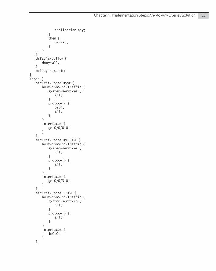
Chapter4:ImplementationSteps:Any-to-AnyOverlaySolution 53
application any; } then { permit; } } } default-policy { deny-all; } policy-rematch;}zones { security-zone Host { host-inbound-traffic { system-services { all; } protocols { ospf; all; } } interfaces { ge-0/0/0.0; } } security-zone UNTRUST { host-inbound-traffic { system-services { all; } protocols { all; } } interfaces { ge-0/0/3.0; } } security-zone TRUST { host-inbound-traffic { system-services { all; } protocols { all; } } interfaces { lo0.0; } }
54 DayOne:BuildingDynamicOverlayService-AwareNetworks
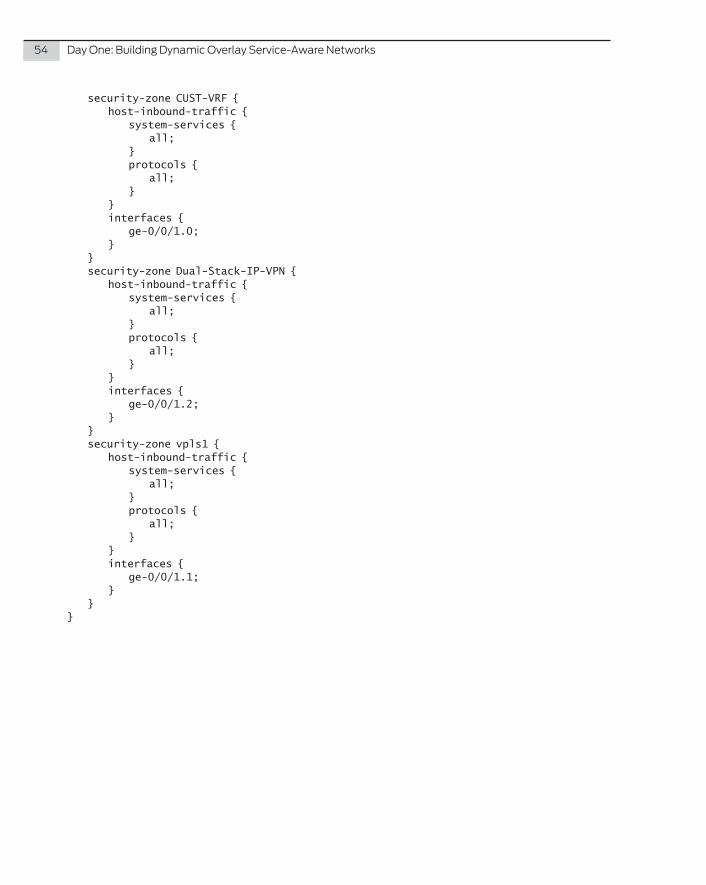
security-zone CUST-VRF { host-inbound-traffic { system-services { all; } protocols { all; } } interfaces { ge-0/0/1.0; } } security-zone Dual-Stack-IP-VPN { host-inbound-traffic { system-services { all; } protocols { all; } } interfaces { ge-0/0/1.2; } } security-zone vpls1 { host-inbound-traffic { system-services { all; } protocols { all; } } interfaces { ge-0/0/1.1; } }}
Chapter4:ImplementationSteps:Any-to-AnyOverlaySolution 55
PacketForwardingApproach
On the SRX platform, one can disable all flow services, enabling the device to be able to be configured much like the MX series. To disable the flow-based services configure the following under the security stanza.
To enable this mode, all security policies must be deleted. Additionally, there is no need to configure selective packet filters on the appropriate interfaces:
forwarding-options { family { inet6 { mode packet-based; } mpls { mode packet-based; } }}
MORE? For further information on the concept of packet versus flow-based forwarding and selective packet mode please refer to the following app note: http://www.juniper.net/us/en/local/pdf/app-notes/3500192-en.pdf; documentation http://www.juniper.net/techpubs/software/junos-securi-ty/junos-security10.1/junos-security-admin-guide/packet-flow-based-fwd-section.html; or book, http://www.juniper.net/us/en/training/jnbooks/srx-series.html.

56 DayOne:BuildingDynamicOverlayService-AwareNetworks
This chapter details the configuration details for the hub and spoke secure overlay solution. As previously discussed, this case explicitly assumes that the IP WAN is untrusted, therefore IPsec is a mandatory requirement to secure the data transiting the WAN. The inclusion of IPsec changes the overlay topology to a hub and spoke overlay, with all communication via the hub. For your convenience, Figure 4.1 is repeated here as Figure 5.1. Also, notes are placed within the configurations and appear as boldface type.
This section is formated such that an engineer or architect can follow the steps to configure the components in a logical manner and it builds the topology in a step-by-step manner per-device as one would build out the network. The detail in the diagrams and the detailed configuration steps will allow a simple replication in a lab, or even replication to build out at scale.
All salient parts of the configuration are detailed, the only parts that are missing are the authentication and network management elements, such as AAA, SNMP.
In your lab you should use the MX Series running Junos 13.3 or later (due to the service cards), and SRX series and M Series, running Junos 11.4 or later.
Chapter 5
Implementation Steps: Encrypted Hub-Spoke IP Overlay Solution
58 DayOne:BuildingDynamicOverlayService-AwareNetworks
Head-EndBranch 1 - MX
Ethernet
Private Core
Lo0172.20.1.1
OSPF OSPF
(L3 Transport)Core
Protocol
BGP Peering uses loopback addresses - MPLS over GRE data traffic is encapsulated in the GRE header (source and destination == loopback addfresses
Tunneled/Private Protocol
Dynamic GRE Tunnelhead-end 1 source = 172.31.255.31branch source = 172.20.1.1branch source = 172.20.1.2branch source = 172.20.1.3
MP-BGP Peering
L2 ServiceIPv6 VPNIPv4 VPN
Branch 2 - M7i
Private Core
Lo0172.20.1.2
Private Core
Lo0172.20.1.3
inet.0
inet.0
Private IP or L2 BB
inet.0
lo0.0 172.31.255.31
Branch 3 - M7i
VPLS1
VPLS1
VPLS1
L2 ServiceIPv6 VPNIPv4 VPN
L2 ServiceIPv6 VPNIPv4 VPN
VPLS1
vRouter
Ubuntu
DC L3 Fabric inet.0Dual-Stack-IP-
VPN Dual-Stack-IP-
VPN
Dual-Stack-IP-VPN
Dual-Stack-IP-VPN
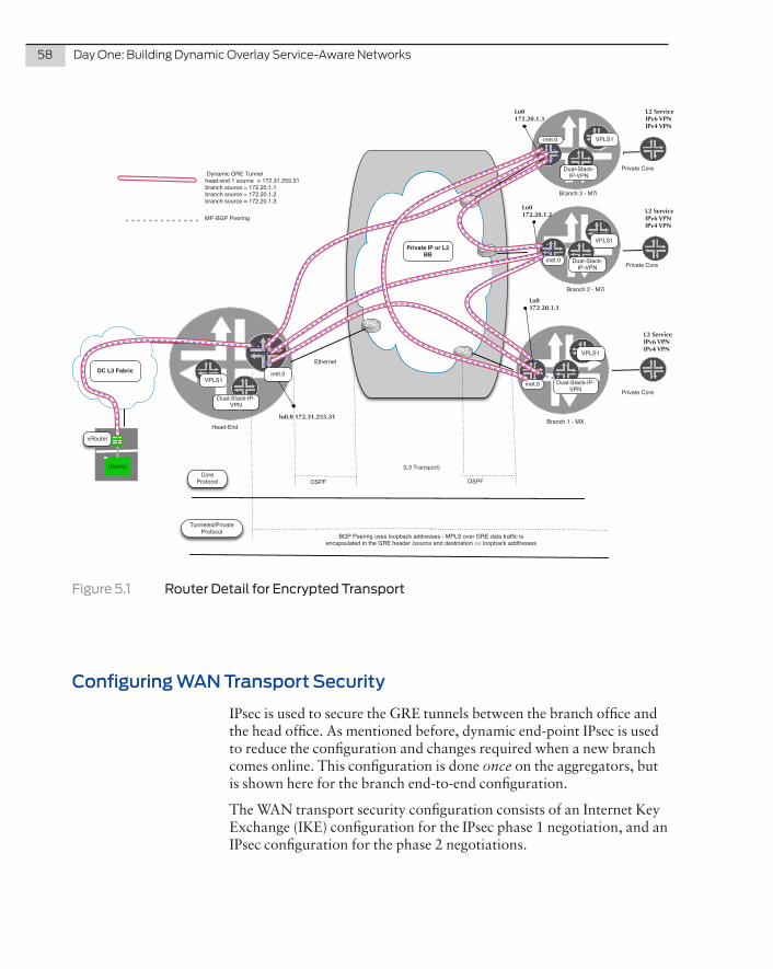
Figure 5.1 Router Detail for Encrypted Transport
Configuring WAN Transport Security
IPsec is used to secure the GRE tunnels between the branch office and the head office. As mentioned before, dynamic end-point IPsec is used to reduce the configuration and changes required when a new branch comes online. This configuration is done once on the aggregators, but is shown here for the branch end-to-end configuration.
The WAN transport security configuration consists of an Internet Key Exchange (IKE) configuration for the IPsec phase 1 negotiation, and an IPsec configuration for the phase 2 negotiations.
Chapter5:ImplementationSteps:EncryptedHub-SpokeIPOverlaySolution 59
SharedKey
For IKE phase 1 negotiation with the Hub, configure an Internet Key Exchange (IKE) proposal and policy.
NOTE This is configured under security on the SRX and services on the M and MX.
Configure an IKE proposal and policy that matches the proposal configured on the Hub router. Note the option of establishing tunnels immediately:
[edit] ike { proposal ike-phase1-proposal { authentication-method pre-shared-keys; dh-group group2; authentication-algorithm sha-256; encryption-algorithm aes-256-cbc; lifetime-seconds 28800; } policy ike-phase1-policy { mode main; proposals ike-phase1-proposal; pre-shared-key ascii-text "$9$nHyW9tOhSeX7V1R7VwYZG69Ap1RcylMLx"; ## SECRET-DATA } } establish-tunnels immediately;
For IPsec phase 2 negotiations, configure an IPsec proposal and policy on the Spoke.
NOTE Sha1-96 needs to be used, as sha-256 is not supported on the M series. If you're using either a MX/SRX, hmac-sha-256-128 can be used:
For Spoke Sites
IPsec { proposal IPsec_proposal { protocol esp; authentication-algorithm hmac-sha1-96; encryption-algorithm aes-256-cbc; } policy IPsec_policy { perfect-forward-secrecy { keys group2; } proposals IPsec_proposal; } }
60 DayOne:BuildingDynamicOverlayService-AwareNetworks
For Hub (Uses Dynamic IPsec)
IPsec-vpn { IPsec { proposal dynamic_IPsec_proposal { protocol esp; authentication-algorithm hmac-sha1-96; encryption-algorithm aes-256-cbc; } policy dynamic_IPsec_policy { perfect-forward-secrecy { keys group2; } proposals dynamic_IPsec_proposal; }
PKI-BasedCertificateAuthentication
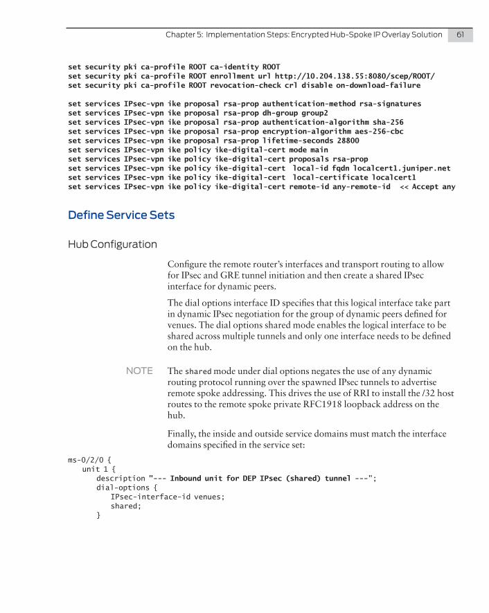
These set commands detail the certificate configuration on the spokes and the hub:
For Spokes
set security pki ca-profile ROOT ca-identity ROOTset security pki ca-profile ROOT enrollment url http://10.204.138.55:8080/scep/ROOT/set security pki ca-profile ROOT revocation-check crl disable on-download-failure
set security ike proposal rsa-prop authentication-method rsa-signaturesset security ike proposal rsa-prop dh-group group2set security ike proposal rsa-prop authentication-algorithm sha1set security ike proposal rsa-prop encryption-algorithm aes-128-cbcset security ike proposal rsa-prop lifetime-seconds 28800
set security ike policy ike-digital-cert mode mainset security ike policy ike-digital-cert proposals rsa-propset security ike policy ike-digital-cert certificate local-certificate localcert11
set security ike gateway gw-branch ike-policy ike-phase1-policyset security ike gateway gw-branch address 191.15.100.6set security ike gateway gw-branch local-identity hostname localcert11.juniper.netset security ike gateway gw-branch external-interface ge-0/0/12
For Hub
The difference here is that the hub is configured for any-remote-id – allowing the hub to accept any new spoke that comes on line. The other option is to manually add each certificate – per spoke:
Chapter5:ImplementationSteps:EncryptedHub-SpokeIPOverlaySolution 61
set security pki ca-profile ROOT ca-identity ROOTset security pki ca-profile ROOT enrollment url http://10.204.138.55:8080/scep/ROOT/set security pki ca-profile ROOT revocation-check crl disable on-download-failure
set services IPsec-vpn ike proposal rsa-prop authentication-method rsa-signaturesset services IPsec-vpn ike proposal rsa-prop dh-group group2set services IPsec-vpn ike proposal rsa-prop authentication-algorithm sha-256set services IPsec-vpn ike proposal rsa-prop encryption-algorithm aes-256-cbcset services IPsec-vpn ike proposal rsa-prop lifetime-seconds 28800set services IPsec-vpn ike policy ike-digital-cert mode mainset services IPsec-vpn ike policy ike-digital-cert proposals rsa-propset services IPsec-vpn ike policy ike-digital-cert local-id fqdn localcert1.juniper.netset services IPsec-vpn ike policy ike-digital-cert local-certificate localcert1set services IPsec-vpn ike policy ike-digital-cert remote-id any-remote-id << Accept any
Define Service Sets
HubConfiguration
Configure the remote router’s interfaces and transport routing to allow for IPsec and GRE tunnel initiation and then create a shared IPsec interface for dynamic peers.
The dial options interface ID specifies that this logical interface take part in dynamic IPsec negotiation for the group of dynamic peers defined for venues. The dial options shared mode enables the logical interface to be shared across multiple tunnels and only one interface needs to be defined on the hub.
NOTE The shared mode under dial options negates the use of any dynamic routing protocol running over the spawned IPsec tunnels to advertise remote spoke addressing. This drives the use of RRI to install the /32 host routes to the remote spoke private RFC1918 loopback address on the hub.
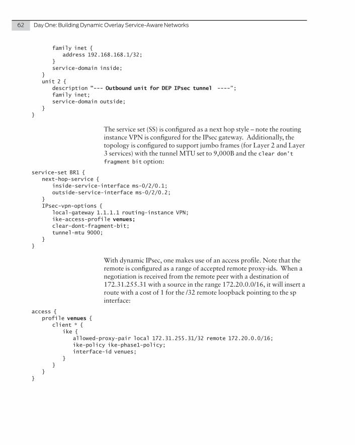
Finally, the inside and outside service domains must match the interface domains specified in the service set:
ms-0/2/0 { unit 1 { description "--- Inbound unit for DEP IPsec (shared) tunnel ---"; dial-options { IPsec-interface-id venues; shared; }
62 DayOne:BuildingDynamicOverlayService-AwareNetworks
family inet { address 192.168.168.1/32; } service-domain inside; } unit 2 { description "--- Outbound unit for DEP IPsec tunnel ----"; family inet; service-domain outside; }}
The service set (SS) is configured as a next hop style – note the routing instance VPN is configured for the IPsec gateway. Additionally, the topology is configured to support jumbo frames (for Layer 2 and Layer 3 services) with the tunnel MTU set to 9,000B and the clear don’t fragment bit option:
service-set BR1 { next-hop-service { inside-service-interface ms-0/2/0.1; outside-service-interface ms-0/2/0.2; } IPsec-vpn-options { local-gateway 1.1.1.1 routing-instance VPN; ike-access-profile venues; clear-dont-fragment-bit; tunnel-mtu 9000; }}
With dynamic IPsec, one makes use of an access profile. Note that the remote is configured as a range of accepted remote proxy-ids. When a negotiation is received from the remote peer with a destination of 172.31.255.31 with a source in the range 172.20.0.0/16, it will insert a route with a cost of 1 for the /32 remote loopback pointing to the sp interface:
access { profile venues { client * { ike { allowed-proxy-pair local 172.31.255.31/32 remote 172.20.0.0/16; ike-policy ike-phase1-policy; interface-id venues; } } }}
Chapter5:ImplementationSteps:EncryptedHub-SpokeIPOverlaySolution 63
SpokeConfiguration
The spoke configuration is easier to configure as it communicates with the hub in a standard P2P manner.
Note these considerations:
� Only traffic from the local loopback to the hub loopback address is allowed.
� The tunnel’s MTU must match that of the hub (9000B tunnel MTU) – note that the physical SP and GE core interfaces have an MTU of 1500 for IP.
� Clear the DF bit to allow fragmentation of ESP traffic, which is then reassembled to allow jumbo frame support (with DF bit set).
� DPD is used to detect a head-end failure – though what is really relied upon to trigger a topology change is the BGP router peering and the associated MH BFD.
� The proxy-id peer rule is term 1 in the IPsec-VPN rule. Note it matches the local address in the hub’s proxy pair rule and the source falls within the hub remote range.
On M and MX Series Platforms
Step 1: Create the Service-Set Interfaces
sp-0/1/0 { unit 0 { family inet; } unit 1 { description IPsec_INSIDE; family inet; service-domain inside; } unit 2 { description IPsec_OUTSIDE; family inet; service-domain outside; }}
64 DayOne:BuildingDynamicOverlayService-AwareNetworks
Step 2: Create the IPsec VPN Rules
IPsec-vpn { rule To_HEAD-END { term 1 { from { source-address { 172.20.1.2/32; } destination-address { 172.31.255.31/32; } } then { remote-gateway 1.1.1.1; dynamic { ike-policy ike-phase1-policy; IPsec-policy IPsec_policy; } clear-dont-fragment-bit; tunnel-mtu 9000; << MTU of tunneled traffic initiate-dead-peer-detection; dead-peer-detection { interval 20; threshold 5; } } } match-direction input; }
On SRX Series Platforms
Here the IPsec-VPN rule and gateway are configured a little differently on the SRX, on this platform the gateway is defined under the IKE stanza and then referenced in the IPsec stanza. The proxy-id is config-ured explicitly within the IPsec->IKE sub-stanza.
NOTE Only a single local and remote can be configured in an IPsec-VPN rule – or proxy-id term. To allow other types of traffic into the IPsec tunnel one makes the rule less specific, or adds another term, in which case a new IPsec SA (in and out) tunnel is created for a given IKE security association.
Chapter5:ImplementationSteps:EncryptedHub-SpokeIPOverlaySolution 65
Step 1: Create the Service Interface
st0 { unit 0 { family inet; }}
Step 2: Create the IPsec VPN Rule
IPsec {vpn To_HEAD-END1 { bind-interface st0.0; df-bit clear; ike { gateway To_HEAD-END1; proxy-identity { local 172.20.1.1/32; remote 172.31.255.31/32; } IPsec-policy IPsec-phase2-policy; } establish-tunnels immediately; } }
ike { gateway To_HEAD-END1 { ike-policy ike-phase1-policy; address 1.1.1.1; dead-peer-detection { always-send; interval 10; threshold 5; } external-interface ge-0/0/3; } }
Now that the IPsec policies, profiles, and the next-hop service sets are configured, let’s configure the platforms to build the IPsec tunnels, the GRE overlay, and the protocol peering over the IPsec tunnels.
66 DayOne:BuildingDynamicOverlayService-AwareNetworks
Hub Sample Configuration
Step 1: Configure Interfaces and Routing Instance to Terminate IPsec and Dynamic GRE Tunnels .
Configure the interfaces that are “public network facing.” In this case there are three physical interfaces and a loopback unit used for IPsec tunnel termination.
Note that on interface ge-1/0/1, flexible Ethernet services and flexible VLAN tagging are used to allow VLAN, QinQ, and VLAN-VPLS configuration on units of the same IFD. (Only unit 0 is detailed here):
interfaces {ge-1/0/1 { flexible-vlan-tagging; encapsulation flexible-ethernet-services; unit 0 { vlan-id 1; family inet { address 172.16.32.10/30; } } } ge-1/0/3 { unit 0 { family inet { address 172.16.40.1/30; } } } ge-1/0/7 { unit 0 { family inet { address 20.20.20.2/24; } } } lo0 {unit 2 { family inet { address 1.1.1.1/32; } } }
Create the VPN virtual router routing instance and add the Ethernet interface to the external, public, the loopback interface (which is the remote endpoint for the remote), and the IPsec interfaces.
Chapter5:ImplementationSteps:EncryptedHub-SpokeIPOverlaySolution 67
OSPF is configured as the protocol to advertise the hub and remote addresses to build the IPsec tunnel. In most cases, when the transport is the Internet, a static route is configured to explicit remote tunnel endpoints or a single default route is configured:
routing-instances { VPN { instance-type virtual-router; interface ms-0/2/0.2; interface ge-1/0/1.0; interface ge-1/0/3.0; interface ge-1/0/7.0; interface lo0.2; # Used as the IPsec tunnel address protocols { ospf { area 0.0.0.0 { interface ge-1/0/1.0 { interface-type p2p; } interface lo0.2; interface ge-1/0/7.0 { interface-type p2p; } interface ge-1/0/3.0 { interface-type p2p; } } } } }
Step 2: Configure System Loopback
The loopback will be used as the router-id, next-hop, BGP peering address, and as the address used by the Dynamic GRE:
lo0 {unit 1 { family inet { address 172.31.255.31/32; } family inet6; family mpls; }}
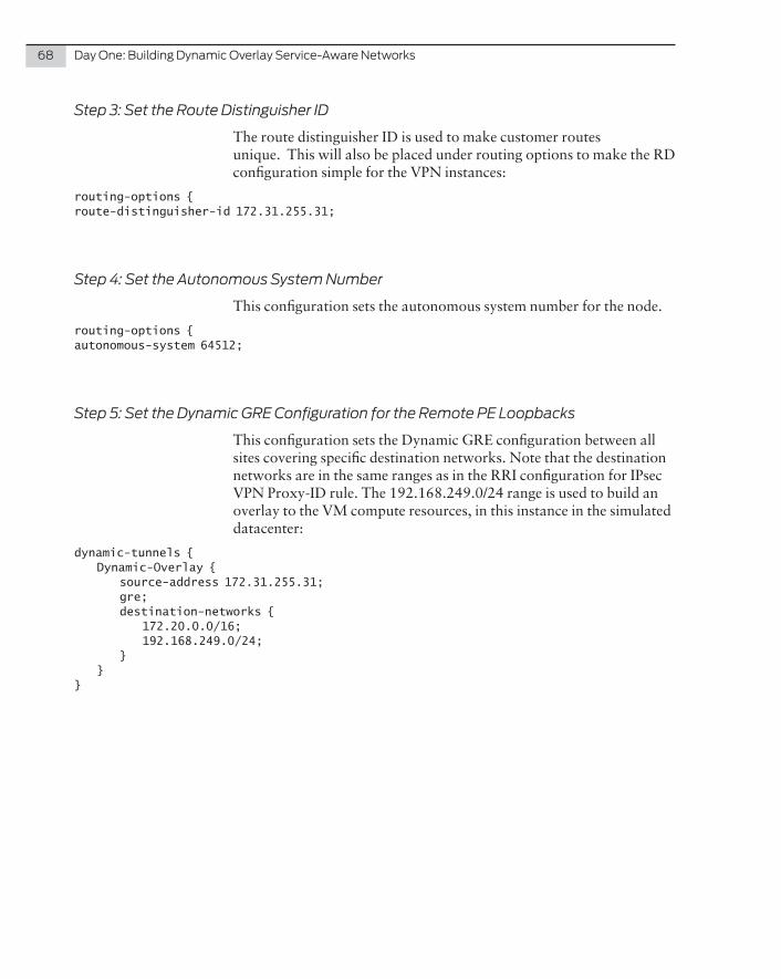
68 DayOne:BuildingDynamicOverlayService-AwareNetworks
Step 3: Set the Route Distinguisher ID
The route distinguisher ID is used to make customer routes unique. This will also be placed under routing options to make the RD configuration simple for the VPN instances:
routing-options {route-distinguisher-id 172.31.255.31;
Step 4: Set the Autonomous System Number
This configuration sets the autonomous system number for the node.
routing-options {autonomous-system 64512;
Step 5: Set the Dynamic GRE Configuration for the Remote PE Loopbacks
This configuration sets the Dynamic GRE configuration between all sites covering specific destination networks. Note that the destination networks are in the same ranges as in the RRI configuration for IPsec VPN Proxy-ID rule. The 192.168.249.0/24 range is used to build an overlay to the VM compute resources, in this instance in the simulated datacenter:
dynamic-tunnels { Dynamic-Overlay { source-address 172.31.255.31; gre; destination-networks { 172.20.0.0/16; 192.168.249.0/24; } }}
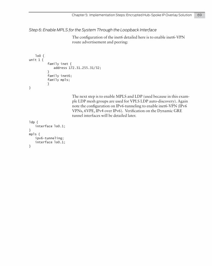
Chapter5:ImplementationSteps:EncryptedHub-SpokeIPOverlaySolution 69
Step 6: Enable MPLS for the System Through the Loopback Interface
The configuration of the inet6 detailed here is to enable inet6-VPN route advertisement and peering:
lo0 {unit 1 { family inet { address 172.31.255.31/32; } family inet6; family mpls; }}
The next step is to enable MPLS and LDP (used because in this exam-ple LDP mesh groups are used for VPLS LDP auto-discovery). Again note the configuration on IPv6-tunneling to enable inet6-VPN (IPv6 VPNs, 6VPE, IPv4 over IPv6). Verification on the Dynamic GRE tunnel interfaces will be detailed later.
ldp { interface lo0.1;}mpls { ipv6-tunneling; interface lo0.1;}
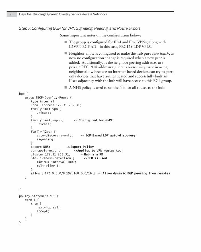
70 DayOne:BuildingDynamicOverlayService-AwareNetworks
Step 7: Configuring BGP for VPN Signaling, Peering, and Route Export
Some important notes on the configuration below:
� The group is configured for IPv4 and IPv6 VPNs, along with L2VPN BGP AD – in this case, FEC129 LDP VPLS.
� Neighbor allow is configured to make the hub pure zero touch, as now no configuration change is required when a new peer is added. Additionally, as the neighbor peering addresses are private RFC1918 addresses, there is no security issue in using neighbor allow because no Internet-based devices can try to peer; only devices that have authenticated and successfully built an IPsec adjacency with the hub will have access to this BGP group.
� A NHS policy is used to set the NH for all routes to the hub:
bgp { group iBGP-Overlay-Peers { type internal; local-address 172.31.255.31; family inet-vpn { unicast; } family inet6-vpn { << Configured for 6vPE unicast; } family l2vpn { auto-discovery-only; << BGP Based LDP auto-discovery signaling; } export NHS; <<Export Policy vpn-apply-export; <<Applies to VPN routes too cluster 172.31.255.31; <<Hub is a RR bfd-liveness-detection { <<BFD is used minimum-interval 1000; multiplier 3; } allow [ 172.0.0.0/8 192.168.0.0/16 ]; << Allow dynamic BGP peering from remotes }
}
policy-statement NHS { term 1 { then { next-hop self; accept; } }}
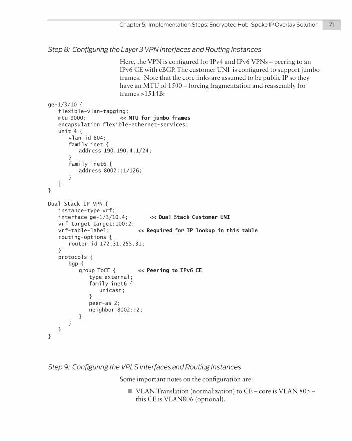
Chapter5:ImplementationSteps:EncryptedHub-SpokeIPOverlaySolution 71
Step 8: Configuring the Layer 3 VPN Interfaces and Routing Instances
Here, the VPN is configured for IPv4 and IPv6 VPNs – peering to an IPv6 CE with eBGP. The customer UNI is configured to support jumbo frames. Note that the core links are assumed to be public IP so they have an MTU of 1500 – forcing fragmentation and reassembly for frames >1514B:
ge-1/3/10 { flexible-vlan-tagging; mtu 9000; << MTU for jumbo frames encapsulation flexible-ethernet-services; unit 4 { vlan-id 804; family inet { address 190.190.4.1/24; } family inet6 { address 8002::1/126; } }}
Dual-Stack-IP-VPN { instance-type vrf; interface ge-1/3/10.4; << Dual Stack Customer UNI vrf-target target:100:2; vrf-table-label; << Required for IP lookup in this table routing-options { router-id 172.31.255.31; } protocols { bgp { group ToCE { << Peering to IPv6 CE type external; family inet6 { unicast; } peer-as 2; neighbor 8002::2; } } }}
Step 9: Configuring the VPLS Interfaces and Routing Instances
Some important notes on the configuration are:
� VLAN Translation (normalization) to CE – core is VLAN 805 – this CE is VLAN806 (optional).
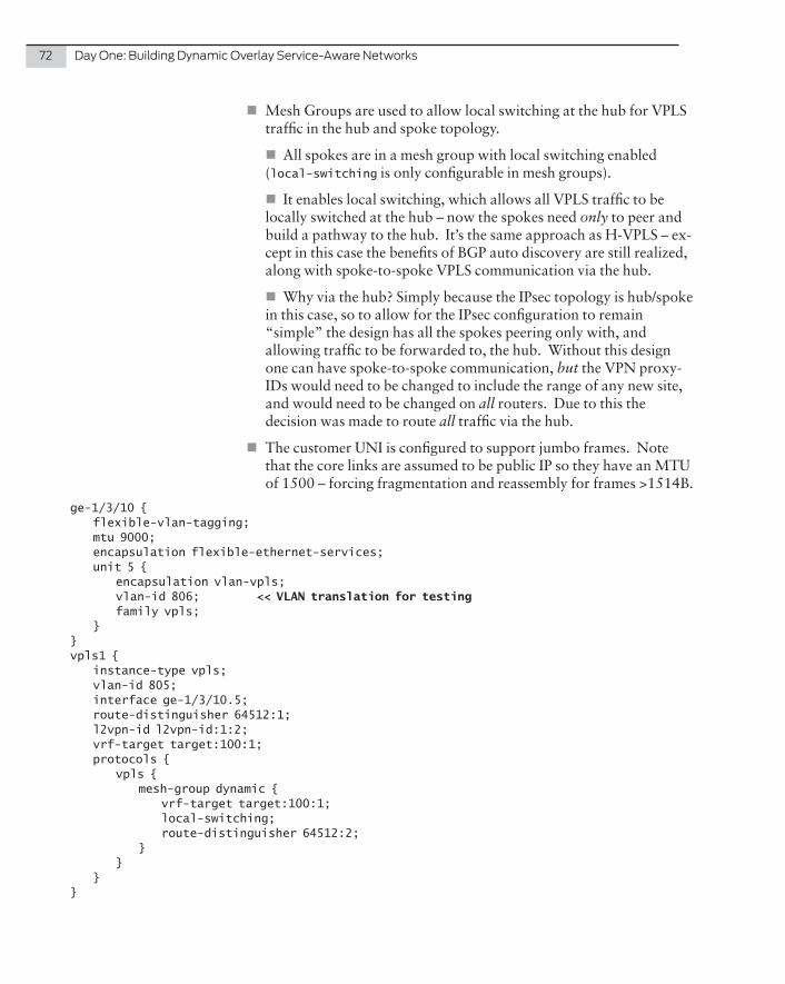
72 DayOne:BuildingDynamicOverlayService-AwareNetworks
� Mesh Groups are used to allow local switching at the hub for VPLS traffic in the hub and spoke topology.
� All spokes are in a mesh group with local switching enabled (local-switching is only configurable in mesh groups).
� It enables local switching, which allows all VPLS traffic to be locally switched at the hub – now the spokes need only to peer and build a pathway to the hub. It’s the same approach as H-VPLS – ex-cept in this case the benefits of BGP auto discovery are still realized, along with spoke-to-spoke VPLS communication via the hub.
� Why via the hub? Simply because the IPsec topology is hub/spoke in this case, so to allow for the IPsec configuration to remain “simple” the design has all the spokes peering only with, and allowing traffic to be forwarded to, the hub. Without this design one can have spoke-to-spoke communication, but the VPN proxy-IDs would need to be changed to include the range of any new site, and would need to be changed on all routers. Due to this the decision was made to route all traffic via the hub.
� The customer UNI is configured to support jumbo frames. Note that the core links are assumed to be public IP so they have an MTU of 1500 – forcing fragmentation and reassembly for frames >1514B.
ge-1/3/10 { flexible-vlan-tagging; mtu 9000; encapsulation flexible-ethernet-services; unit 5 { encapsulation vlan-vpls; vlan-id 806; << VLAN translation for testing family vpls; }}vpls1 { instance-type vpls; vlan-id 805; interface ge-1/3/10.5; route-distinguisher 64512:1; l2vpn-id l2vpn-id:1:2; vrf-target target:100:1; protocols { vpls { mesh-group dynamic { vrf-target target:100:1; local-switching; route-distinguisher 64512:2; } } }}
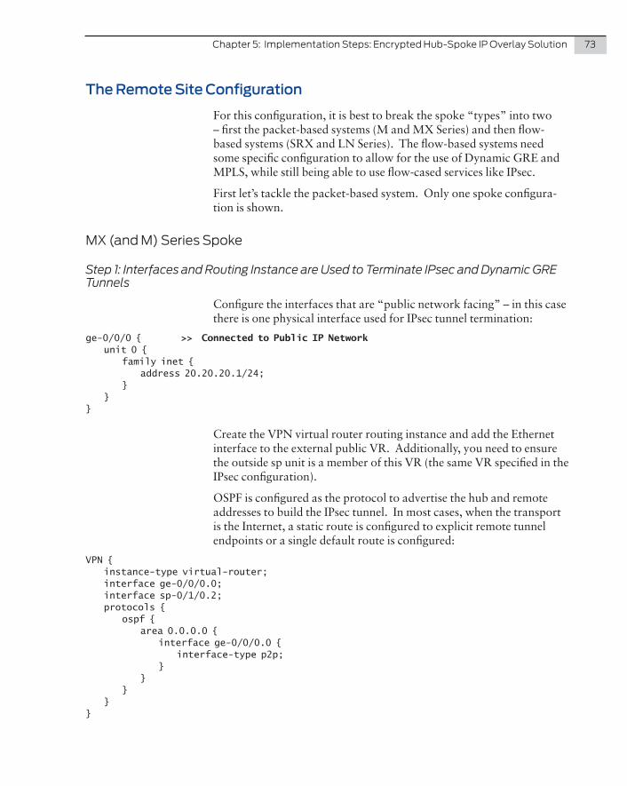
Chapter5:ImplementationSteps:EncryptedHub-SpokeIPOverlaySolution 73
The Remote Site Configuration
For this configuration, it is best to break the spoke “types” into two – first the packet-based systems (M and MX Series) and then flow-based systems (SRX and LN Series). The flow-based systems need some specific configuration to allow for the use of Dynamic GRE and MPLS, while still being able to use flow-cased services like IPsec.
First let’s tackle the packet-based system. Only one spoke configura-tion is shown.
MX(andM)SeriesSpoke
Step 1: Interfaces and Routing Instance are Used to Terminate IPsec and Dynamic GRE Tunnels
Configure the interfaces that are “public network facing” – in this case there is one physical interface used for IPsec tunnel termination:
ge-0/0/0 { >> Connected to Public IP Network unit 0 { family inet { address 20.20.20.1/24; } }}
Create the VPN virtual router routing instance and add the Ethernet interface to the external public VR. Additionally, you need to ensure the outside sp unit is a member of this VR (the same VR specified in the IPsec configuration).
OSPF is configured as the protocol to advertise the hub and remote addresses to build the IPsec tunnel. In most cases, when the transport is the Internet, a static route is configured to explicit remote tunnel endpoints or a single default route is configured:
VPN { instance-type virtual-router; interface ge-0/0/0.0; interface sp-0/1/0.2; protocols { ospf { area 0.0.0.0 { interface ge-0/0/0.0 { interface-type p2p; } } } }}
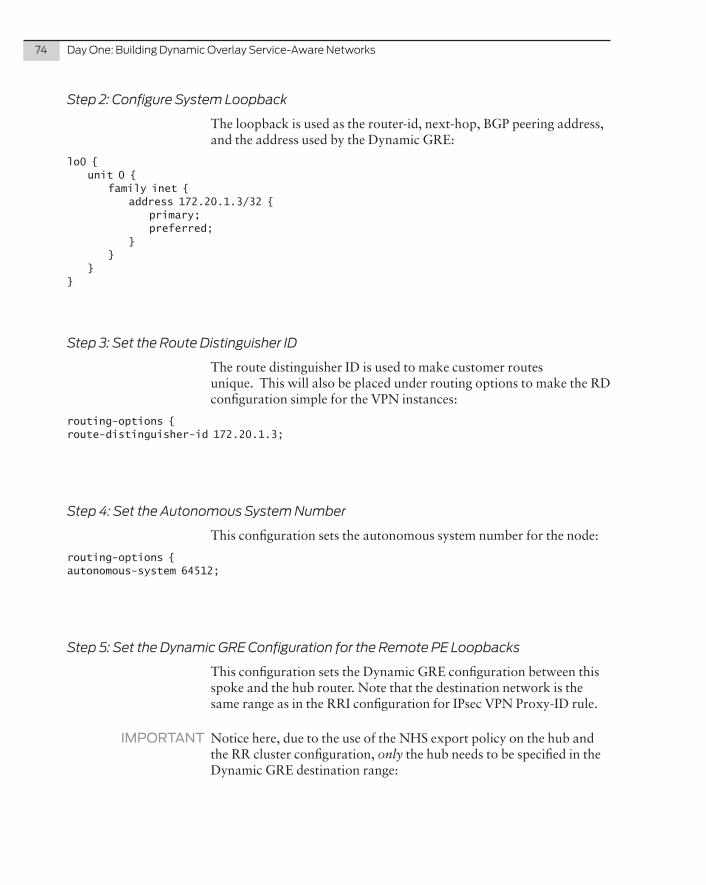
74 DayOne:BuildingDynamicOverlayService-AwareNetworks
Step 2: Configure System Loopback
The loopback is used as the router-id, next-hop, BGP peering address, and the address used by the Dynamic GRE:
lo0 { unit 0 { family inet { address 172.20.1.3/32 { primary; preferred; } } }}
Step 3: Set the Route Distinguisher ID
The route distinguisher ID is used to make customer routes unique. This will also be placed under routing options to make the RD configuration simple for the VPN instances:
routing-options {route-distinguisher-id 172.20.1.3;
Step 4: Set the Autonomous System Number
This configuration sets the autonomous system number for the node:
routing-options {autonomous-system 64512;
Step 5: Set the Dynamic GRE Configuration for the Remote PE Loopbacks
This configuration sets the Dynamic GRE configuration between this spoke and the hub router. Note that the destination network is the same range as in the RRI configuration for IPsec VPN Proxy-ID rule.
IMPORTANT Notice here, due to the use of the NHS export policy on the hub and the RR cluster configuration, only the hub needs to be specified in the Dynamic GRE destination range:
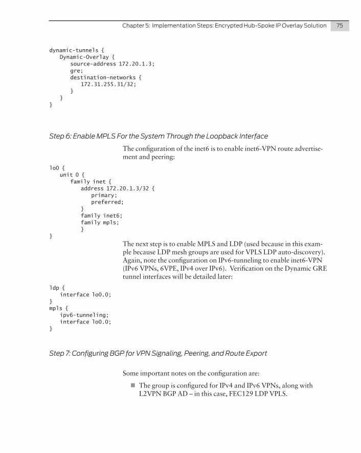
Chapter5:ImplementationSteps:EncryptedHub-SpokeIPOverlaySolution 75
dynamic-tunnels { Dynamic-Overlay { source-address 172.20.1.3; gre; destination-networks { 172.31.255.31/32; } }}
Step 6: Enable MPLS For the System Through the Loopback Interface
The configuration of the inet6 is to enable inet6-VPN route advertise-ment and peering:
lo0 { unit 0 { family inet { address 172.20.1.3/32 { primary; preferred; } family inet6; family mpls; }}
The next step is to enable MPLS and LDP (used because in this exam-ple because LDP mesh groups are used for VPLS LDP auto-discovery). Again, note the configuration on IPv6-tunneling to enable inet6-VPN (IPv6 VPNs, 6VPE, IPv4 over IPv6). Verification on the Dynamic GRE tunnel interfaces will be detailed later:
ldp { interface lo0.0;}mpls { ipv6-tunneling; interface lo0.0;}
Step 7: Configuring BGP for VPN Signaling, Peering, and Route Export
Some important notes on the configuration are:
� The group is configured for IPv4 and IPv6 VPNs, along with L2VPN BGP AD – in this case, FEC129 LDP VPLS.
76 DayOne:BuildingDynamicOverlayService-AwareNetworks
� Because the hub is using neighbor allow it will not initiate a BGP peering connection. The spokes are configured with the IP address of one (or more hubs).
� BFD is used to speed up detection of a failed hub, or failure in the IPsec tunnel:
bgp { group iBGP-Overlay-Peers { type internal; local-address 172.20.1.3; family inet-vpn { << IPv4 VPN unicast; } family inet6-vpn { << IPv6 VPN unicast; } family l2vpn { auto-discovery-only; signaling; } bfd-liveness-detection { minimum-interval 1000; multiplier 3; } neighbor 172.31.255.31; << Note here that the peer is statically defined (hub IP) }}
Okay, how do you reach this BGP peer address? Unlike on the hub, where the routes to the remote BGP peering addressing are dynamically inserted using reverse route insertion, here static routing is configured to the hub loopback IP pointing to the appropriate sp unit.
It’s scalable because no routing protocol is running over the IPsec tunnel (only BGP peering) and only one /32 host route is required for each hub – this never changes.
static { route 172.31.255.31/32 next-hop sp-0/1/0.1;}
Note the sp unit 1 is left in inet.0 – this is another benefit of using next hop style service-sets.
Chapter5:ImplementationSteps:EncryptedHub-SpokeIPOverlaySolution 77
Step 8: Configuring the Layer 3 VPN Interfaces and Routing Instances
Some important notes on the following configuration are:
� The VPN is configured for IPv4 and IPv6 VPNs – peering to an IPv6 CE with eBGP.
� The customer UNI is configured to support jumbo frames. Note that the core links are assumed to be public IP so they have an MTU of 1500 – forcing fragmentation and reassembly for frames >1514B.
� In the case of the M series, where VRF-table-label is not avail-able, one needs a VT unit to loop traffic for the lookup with Dynamic GRE:
ge-0/0/3 { flexible-vlan-tagging; mtu 9000; encapsulation flexible-ethernet-services; unit 4 { vlan-id 823; family inet { address 190.192.4.1/24; } family inet6 { address 8001::1/126; } }}vt-1/2/0 { << Configure vt unit. unit 1 { family inet; family inet6; }}
Dual-Stack-IP-VPN { instance-type vrf; interface ge-0/0/3.4; interface vt-1/2/0.1; << vt interface IS required here to allow IP lookup vrf-target target:100:2; routing-options { router-id 172.20.1.3; } protocols { bgp { group ToCE { << Configure IPv6 CE type external; family inet6 { unicast; }
78 DayOne:BuildingDynamicOverlayService-AwareNetworks
peer-as 1; neighbor 8001::2; } } }}
Step 9: Configuring the VPLS Interfaces and Routing Instances
In the VLAN translation (normalization) to CE, the core is VLAN 805 and this CE is VLAN808 (optional). The customer UNI is configured to support jumbo frames. Note that the core links are assumed to be public IP so they have an MTU of 1500 – forcing fragmentation and reassembly for frames >1514B:
ge-0/0/3 { flexible-vlan-tagging; mtu 9000; encapsulation flexible-ethernet-services; unit 5 { encapsulation vlan-vpls; vlan-id 808; input-vlan-map { << Note vlan-map swap used: s-vlan (VPLS) 805, c-vlan 808 swap; vlan-id 805; } output-vlan-map swap; family vpls; }}
vpls1 { instance-type vpls; interface ge-0/0/3.5; route-distinguisher 64512:1; << Note RD matches mesh-group RD on hub l2vpn-id l2vpn-id:1:2; vrf-target target:100:1; protocols { vpls; }}
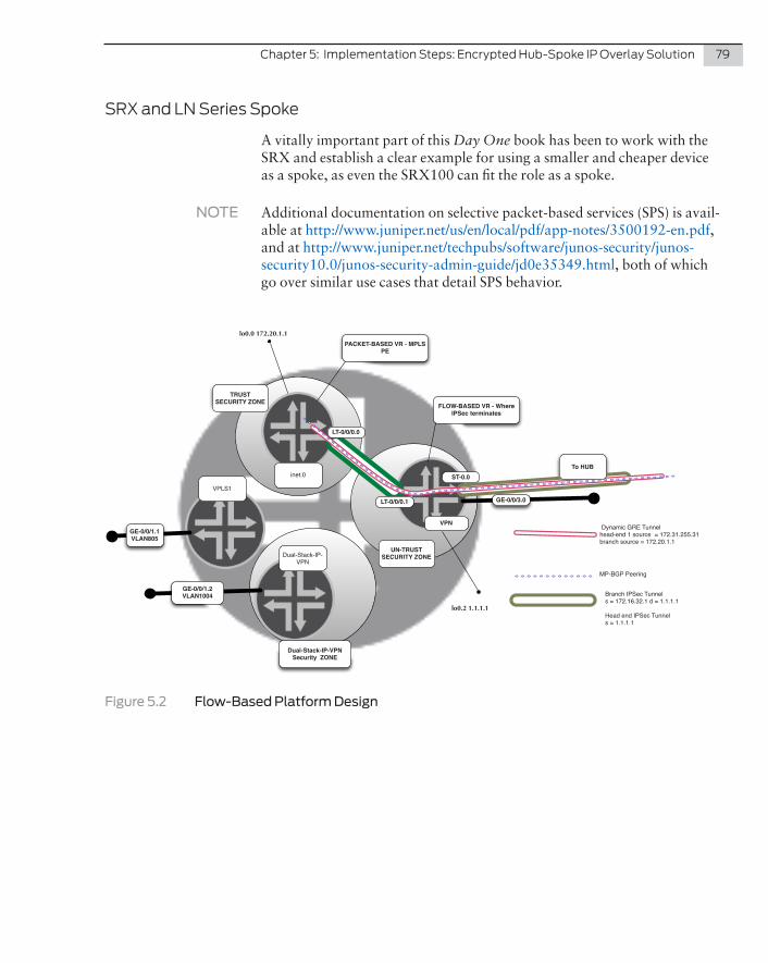
Chapter5:ImplementationSteps:EncryptedHub-SpokeIPOverlaySolution 79
SRXandLNSeriesSpoke
A vitally important part of this Day One book has been to work with the SRX and establish a clear example for using a smaller and cheaper device as a spoke, as even the SRX100 can fit the role as a spoke.
NOTE Additional documentation on selective packet-based services (SPS) is avail-able at http://www.juniper.net/us/en/local/pdf/app-notes/3500192-en.pdf, and at http://www.juniper.net/techpubs/software/junos-security/junos-security10.0/junos-security-admin-guide/jd0e35349.html, both of which go over similar use cases that detail SPS behavior.
inet.0
lo0.0 172.20.1.1
VPN
lo0.2 1.1.1.1
VPLS1
Dual-Stack-IP-VPN
LT-0/0/0.0
To HUB
LT-0/0/0.1 GE-0/0/3.0
ST-0.0
FLOW-BASED VR - Where IPSec terminates
PACKET-BASED VR - MPLS PE
GE-0/0/1.1VLAN805
GE-0/0/1.2VLAN1004
TRUST SECURITY ZONE
UN-TRUST SECURITY ZONE
Dynamic GRE Tunnelhead-end 1 source = 172.31.255.31branch source = 172.20.1.1
MP-BGP Peering
Branch IPSec Tunnels = 172.16.32.1 d = 1.1.1.1
Head end IPSec Tunnels = 1.1.1.1
Dual-Stack-IP-VPN Security ZONE
Figure 5.2 Flow-Based Platform Design

80 DayOne:BuildingDynamicOverlayService-AwareNetworks
Step 1: Interfaces and Routing Instance are Used to Terminate IPsec and Dynamic GRE Tunnels
First you need to configure the interfaces that are “public network facing” – in this case there is one physical interface used for IPsec tunnel termination – the LT interface is used to “connect” the flow-based VR to the packet-based inet.0:
ge-0/0/3 { unit 0 { family inet { address 172.16.32.1/30; } }
Now let’s look at the LT interface configuration in more detail. LT interfaces (in this instance) are configured as a pair, which essentially makes them the equivalent of a software cross-over cable. Traffic entering lt unit 0 comes out unit 1 and vice versa.
Encapsulation is frame-relay with matching DLCI. Why? For Layer 2 encapsulation, so that MPLS and IP will be tunneled over this IFL.
The secret sauce is in the filter “packet-mode” that forces all traffic matching this filter to be treated as packet-based. This is applied on every interface that requires traffic to be treated as packet based (includes CE facing IFLs). Let’s take a look:
lt-0/0/0 { unit 0 { encapsulation frame-relay; dlci 100; peer-unit 1; family inet { filter { input packet-mode; } address 10.1.1.3/32; } family inet6; family mpls; } unit 1 { encapsulation frame-relay; dlci 100; peer-unit 0; family inet; }}
firewall { family inet { filter packet-mode {
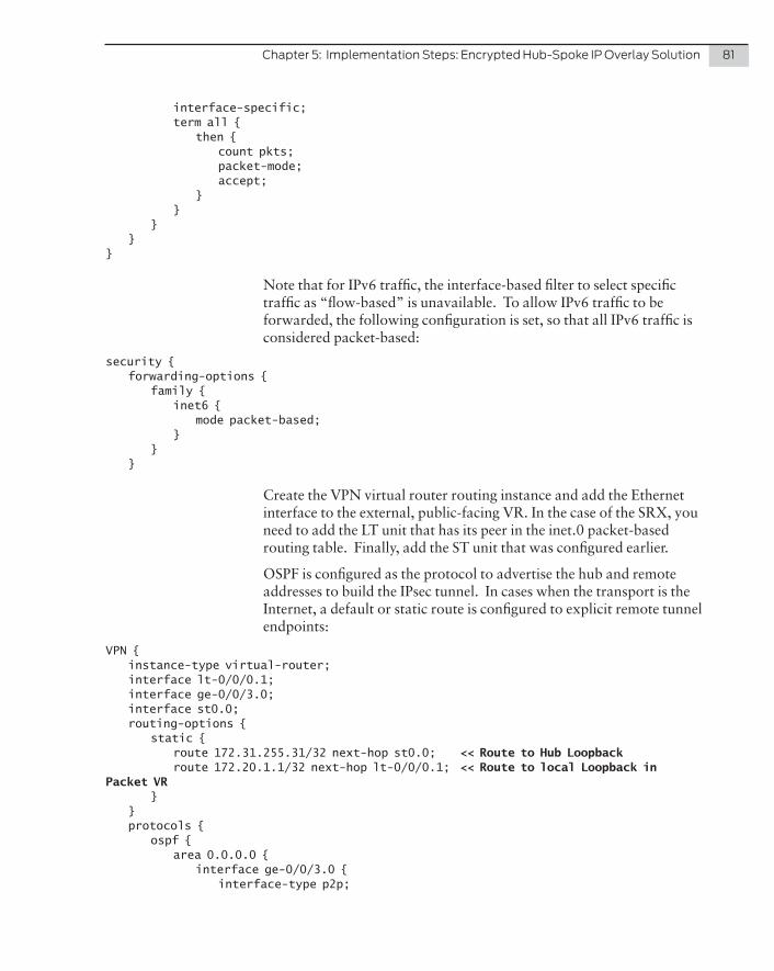
Chapter5:ImplementationSteps:EncryptedHub-SpokeIPOverlaySolution 81
interface-specific; term all { then { count pkts; packet-mode; accept; } } } }}
Note that for IPv6 traffic, the interface-based filter to select specific traffic as “flow-based” is unavailable. To allow IPv6 traffic to be forwarded, the following configuration is set, so that all IPv6 traffic is considered packet-based:
security { forwarding-options { family { inet6 { mode packet-based; } } }
Create the VPN virtual router routing instance and add the Ethernet interface to the external, public-facing VR. In the case of the SRX, you need to add the LT unit that has its peer in the inet.0 packet-based routing table. Finally, add the ST unit that was configured earlier.
OSPF is configured as the protocol to advertise the hub and remote addresses to build the IPsec tunnel. In cases when the transport is the Internet, a default or static route is configured to explicit remote tunnel endpoints:
VPN { instance-type virtual-router; interface lt-0/0/0.1; interface ge-0/0/3.0; interface st0.0; routing-options { static { route 172.31.255.31/32 next-hop st0.0; << Route to Hub Loopback route 172.20.1.1/32 next-hop lt-0/0/0.1; << Route to local Loopback in Packet VR } } protocols { ospf { area 0.0.0.0 { interface ge-0/0/3.0 { interface-type p2p;
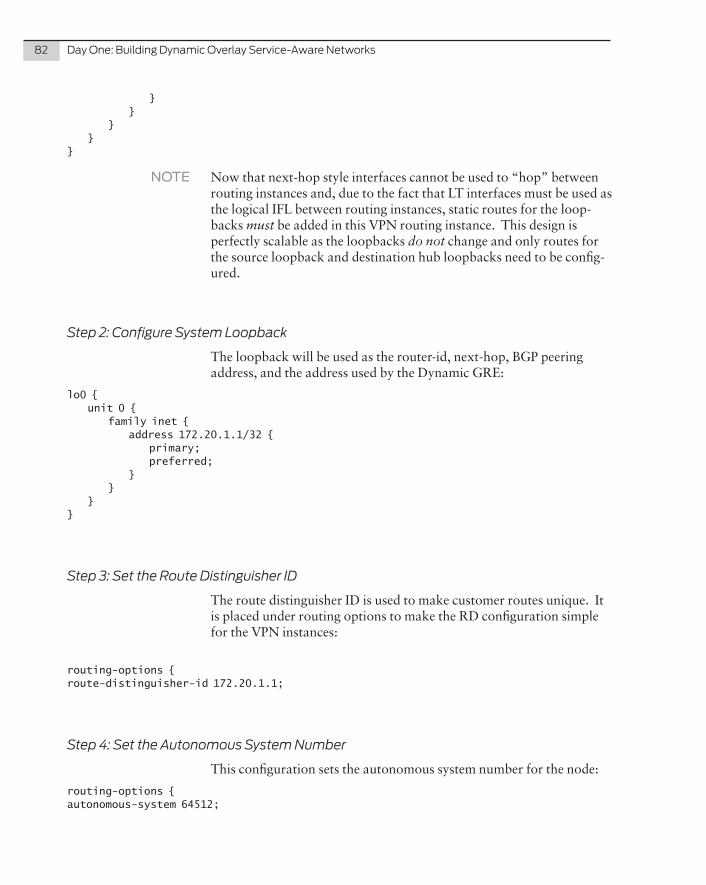
82 DayOne:BuildingDynamicOverlayService-AwareNetworks
} } } }}
NOTE Now that next-hop style interfaces cannot be used to “hop” between routing instances and, due to the fact that LT interfaces must be used as the logical IFL between routing instances, static routes for the loop-backs must be added in this VPN routing instance. This design is perfectly scalable as the loopbacks do not change and only routes for the source loopback and destination hub loopbacks need to be config-ured.
Step 2: Configure System Loopback
The loopback will be used as the router-id, next-hop, BGP peering address, and the address used by the Dynamic GRE:
lo0 { unit 0 { family inet { address 172.20.1.1/32 { primary; preferred; } } }}
Step 3: Set the Route Distinguisher ID
The route distinguisher ID is used to make customer routes unique. It is placed under routing options to make the RD configuration simple for the VPN instances:
routing-options {route-distinguisher-id 172.20.1.1;
Step 4: Set the Autonomous System Number
This configuration sets the autonomous system number for the node:
routing-options {autonomous-system 64512;
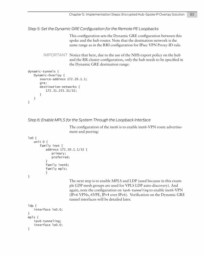
Chapter5:ImplementationSteps:EncryptedHub-SpokeIPOverlaySolution 83
Step 5: Set the Dynamic GRE Configuration for the Remote PE Loopbacks
This configuration sets the Dynamic GRE configuration between this spoke and the hub router. Note that the destination network is the same range as in the RRI configuration for IPsec VPN Proxy-ID rule.
IMPORTANT Notice that here, due to the use of the NHS export policy on the hub and the RR cluster configuration, only the hub needs to be specified in the Dynamic GRE destination range:
dynamic-tunnels { Dynamic-Overlay { source-address 172.20.1.1; gre; destination-networks { 172.31.255.31/32; } }}
Step 6: Enable MPLS for the System Through the Loopback Interface
The configuration of the inet6 is to enable inet6-VPN route advertise-ment and peering:
lo0 { unit 0 { family inet { address 172.20.1.1/32 { primary; preferred; } family inet6; family mpls; }}
The next step is to enable MPLS and LDP (used because in this exam-ple LDP mesh groups are used for VPLS LDP auto-discovery). And again, note the configuration on ipv6-tunneling to enable inet6-VPN (IPv6 VPNs, 6VPE, IPv4 over IPv6). Verification on the Dynamic GRE tunnel interfaces will be detailed later.
ldp { interface lo0.0;}mpls { ipv6-tunneling; interface lo0.0;}

84 DayOne:BuildingDynamicOverlayService-AwareNetworks
Step 7: Configuring BGP for VPN Signaling, Peering, and Route Export
Some important notes on this configuration are:
� The group is configured for IPv4 and IPv6 VPNs, along with L2VPN BGP AD – in this case FEC129 LDP VPLS.
� Because the hub is using neighbor-allow it will not initiate a BGP peering connection, so the spokes are configured with the IP address of one (or more hubs).
� BFD is used to speed up detection of a failed hub, or failure in the IPsec tunnel:
bgp { group iBGP-Overlay-Peers { type internal; local-address 172.20.1.1; family inet-vpn { << IPv4 VPN unicast; } family inet6-vpn { << IPv6 VPN unicast; } family l2vpn { auto-discovery-only; signaling; } bfd-liveness-detection { minimum-interval 1000; multiplier 3; } neighbor 172.31.255.31; << Note here peer is statically defined (hub IP) }}
How do you reach this BGP Peer address? Unlike on the hub, where the routes to the remote BGP peering addressing are dynamically inserted using reverse route insertion, here the static routing is config-ured to the hub loopback IP. The next hop (in inet.0) is the peer LT unit that is in inet.0.
This is scalable because only one /32 host route is required for each hub, (this never changes):
static { route 172.31.255.31/32 next-hop lt-0/0/0.0;}
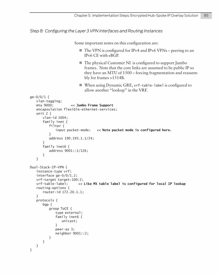
Chapter5:ImplementationSteps:EncryptedHub-SpokeIPOverlaySolution 85
Step 8: Configuring the Layer 3 VPN Interfaces and Routing Instances
Some important notes on this configuration are:
� The VPN is configured for IPv4 and IPv6 VPNs – peering to an IPv6 CE with eBGP.
� The physical Customer NI is configured to support Jumbo frames. Note that the core links are assumed to be public IP so they have an MTU of 1500 – forcing fragmentation and reassem-bly for frames >1514B.
� When using Dynamic GRE, vrf-table-label is configured to allow another “lookup” in the VRF.
ge-0/0/1 { vlan-tagging; mtu 9000; << Jumbo Frame Support encapsulation flexible-ethernet-services; unit 2 { vlan-id 1004; family inet { filter { input packet-mode; << Note packet mode is configured here. } address 190.193.1.1/24; } family inet6 { address 9001::1/126; } }
Dual-Stack-IP-VPN { instance-type vrf; interface ge-0/0/1.2; vrf-target target:100:2; vrf-table-label; << Like MX table label is configured for local IP lookup routing-options { router-id 172.20.1.1; } protocols { bgp { group ToCE { type external; family inet6 { unicast; } peer-as 3; neighbor 9001::2; } } }}
86 DayOne:BuildingDynamicOverlayService-AwareNetworks
Step 9: Configuring the VPLS Interfaces and Routing Instances
Here again, the customer UNI is configured to support jumbo frames. The core links are assumed to be public IP so they have an MTU of 1500 – forcing fragmentation and reassembly for frames >1514B:
ge-0/0/1 { vlan-tagging; mtu 9000; encapsulation flexible-ethernet-services;unit 1 { encapsulation vlan-vpls; vlan-id 805; family vpls; }
Next, no-tunnel-services is configured. L2VPN-ID configured for FEC129 LDP VPLS and RD and RT match the mesh-group on the hub:
vpls1 { instance-type vpls; interface ge-0/0/1.1; route-distinguisher 64512:1; l2vpn-id l2vpn-id:1:2; vrf-target target:100:1; protocols { vpls { no-tunnel-services; } }}
Step 10: Security Zones and Polices on Flow-Based Systems
Although not a specific focus of this Day One book, it is important to note that on flow-based systems one must configure security zones to allow traffic into an interface. The configuration of zones and policies need not match the VPN configuration, but every interface in a zone must be in the same VRF. In this book the zone policies allow all traffic between zones:
security { policies { from-zone Host to-zone Host { policy default-permit { match { source-address any; destination-address any; application any; } then { permit; }
Chapter5:ImplementationSteps:EncryptedHub-SpokeIPOverlaySolution 87
} } from-zone TRUST to-zone UNTRUST { policy ANY { match { source-address any; destination-address any; application any; } then { permit; } } } from-zone UNTRUST to-zone TRUST { policy ANY { match { source-address any; destination-address any; application any; } then { permit; } } } from-zone UNTRUST to-zone UNTRUST { policy ANY { match { source-address any; destination-address any; application any; } then { permit; } } } from-zone TRUST to-zone TRUST { policy ANY { match { source-address any; destination-address any; application any; } then { permit; } } } default-policy { deny-all; } policy-rematch; } zones { security-zone Host {
88 DayOne:BuildingDynamicOverlayService-AwareNetworks
host-inbound-traffic { system-services { all; } protocols { ospf; all; } } interfaces { ge-0/0/0.0; } } security-zone UNTRUST { host-inbound-traffic { system-services { all; } protocols { all; } } interfaces { ge-0/0/3.0; st0.0; lt-0/0/0.1; } } security-zone TRUST { host-inbound-traffic { system-services { all; } protocols { all; } } interfaces { lt-0/0/0.0; lo0.0; } } security-zone Dual-Stack-IP-VPN { host-inbound-traffic { system-services { all; } protocols { all; } } interfaces { ge-0/0/1.2; } }}
Integrating virtualized services, or virtualized remote sites, into this overlay design can be easily achieved. In fact, it is an option to have the vRouter running an SRX image as a remote routing capable site with Layer 4 - Layer 7 services, or alternatively, a hosted data center security service.
There are many examples of configuring the vRouter available, and in the design of this Day One book use case, a simple hosted Ubuntu server is deployed as an example of a hosted service.
The vRouter is configured as a member of the Dual-Stack inet VPN instance – not as a collapsed Option-A (VT connected CE), or as an Option-B.
There are a few important points to consider when integrating this design:
� BGP route export policies need to be configured to set the next hop for the data center services to be the MX data center gateway, and for the remote WAN locations, the remote sites need to have the data center routes advertised with the MX gateway as the next hop.
� This is because the default gateway of the vRouter hypervi-sor may not be towards the data center gateway. In this case only a host route to the data center gateway is required on the hypervisor.
� Setting the next-hop self is done automatically with the IPsec topology where HNS policies are configured to all peers.
Chapter 6
Integrating Virtualized Services (or Virtualized Remote Sites) Into the Overlay Topology
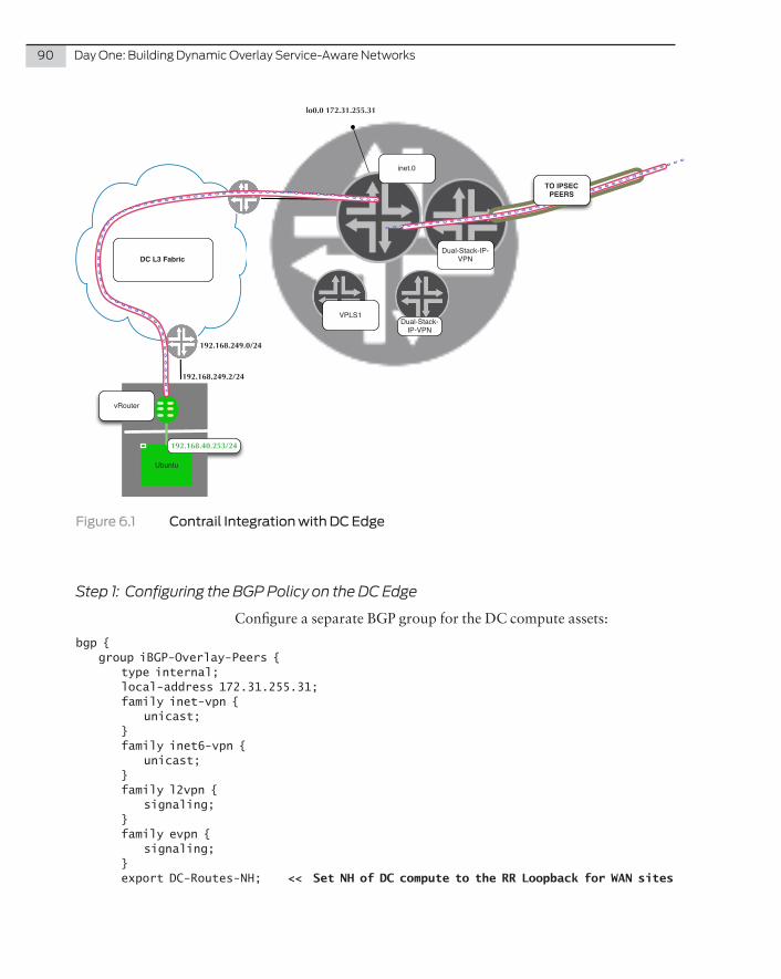
90 DayOne:BuildingDynamicOverlayService-AwareNetworks
inet.0
lo0.0 172.31.255.31
VPLS1
vRouter
Ubuntu
DC L3 Fabric
Dual-Stack-IP-VPN
TO IPSEC PEERS
Dual-Stack-IP-VPN
192.168.249.0/24
192.168.249.2/24
192.168.40.253/24
Figure 6.1 Contrail Integration with DC Edge
Step 1: Configuring the BGP Policy on the DC Edge
Configure a separate BGP group for the DC compute assets:
bgp { group iBGP-Overlay-Peers { type internal; local-address 172.31.255.31; family inet-vpn { unicast; } family inet6-vpn { unicast; } family l2vpn { signaling; } family evpn { signaling; } export DC-Routes-NH; << Set NH of DC compute to the RR Loopback for WAN sites
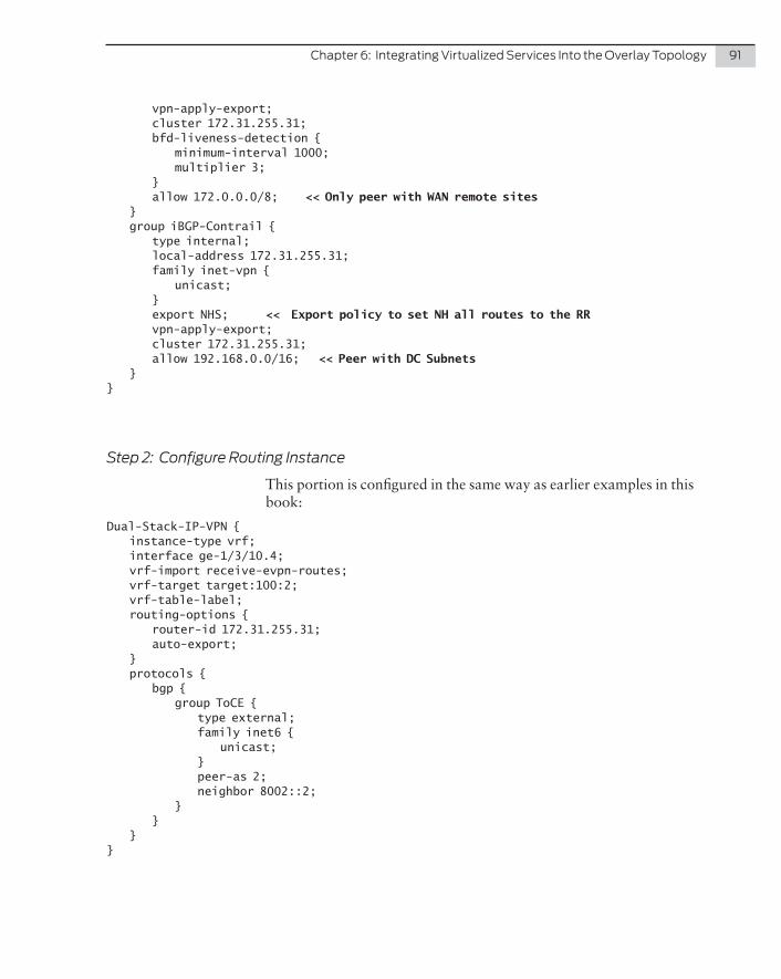
Chapter6:IntegratingVirtualizedServicesIntotheOverlayTopology 91
vpn-apply-export; cluster 172.31.255.31; bfd-liveness-detection { minimum-interval 1000; multiplier 3; } allow 172.0.0.0/8; << Only peer with WAN remote sites } group iBGP-Contrail { type internal; local-address 172.31.255.31; family inet-vpn { unicast; } export NHS; << Export policy to set NH all routes to the RR vpn-apply-export; cluster 172.31.255.31; allow 192.168.0.0/16; << Peer with DC Subnets }}
Step 2: Configure Routing Instance
This portion is configured in the same way as earlier examples in this book:
Dual-Stack-IP-VPN { instance-type vrf; interface ge-1/3/10.4; vrf-import receive-evpn-routes; vrf-target target:100:2; vrf-table-label; routing-options { router-id 172.31.255.31; auto-export; } protocols { bgp { group ToCE { type external; family inet6 { unicast; } peer-as 2; neighbor 8002::2; } } }}
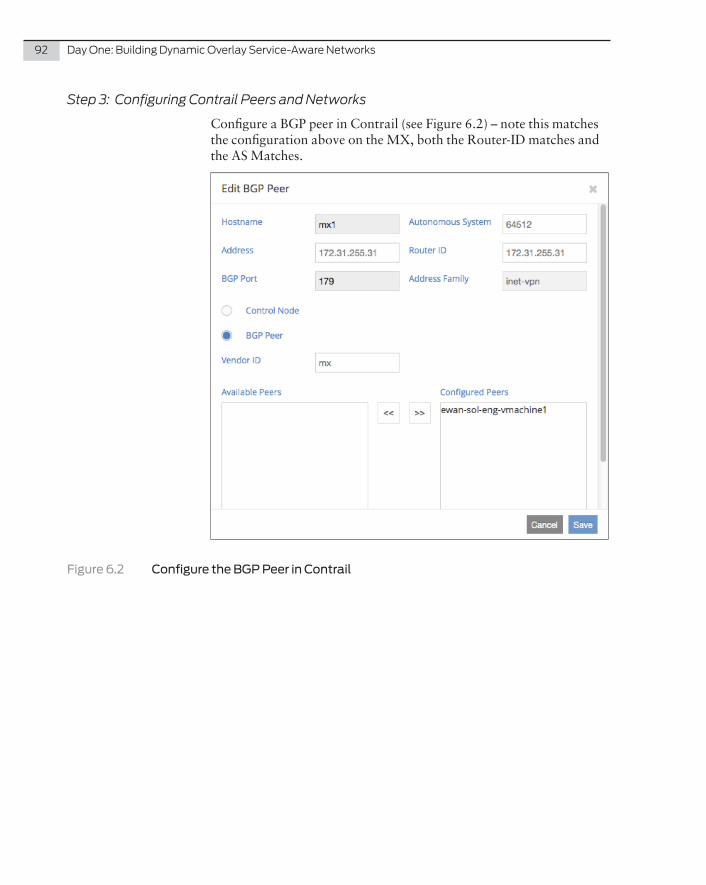
92 DayOne:BuildingDynamicOverlayService-AwareNetworks
Step 3: Configuring Contrail Peers and Networks
Configure a BGP peer in Contrail (see Figure 6.2) – note this matches the configuration above on the MX, both the Router-ID matches and the AS Matches.
Figure 6.2 Configure the BGP Peer in Contrail
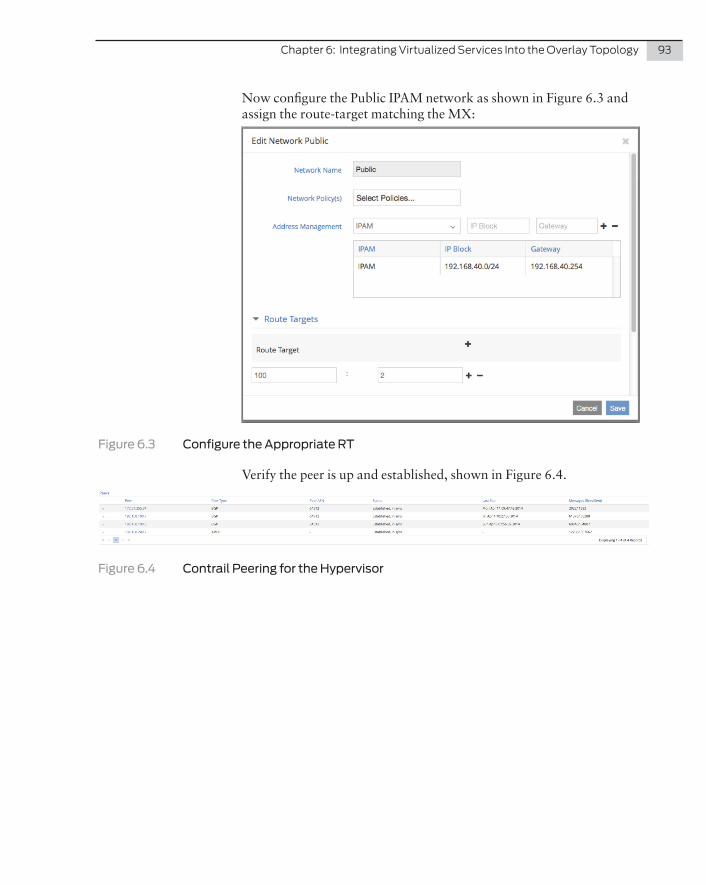
Chapter6:IntegratingVirtualizedServicesIntotheOverlayTopology 93
Now configure the Public IPAM network as shown in Figure 6.3 and assign the route-target matching the MX:
Figure 6.3 Configure the Appropriate RT
Verify the peer is up and established, shown in Figure 6.4.
Figure 6.4 Contrail Peering for the Hypervisor
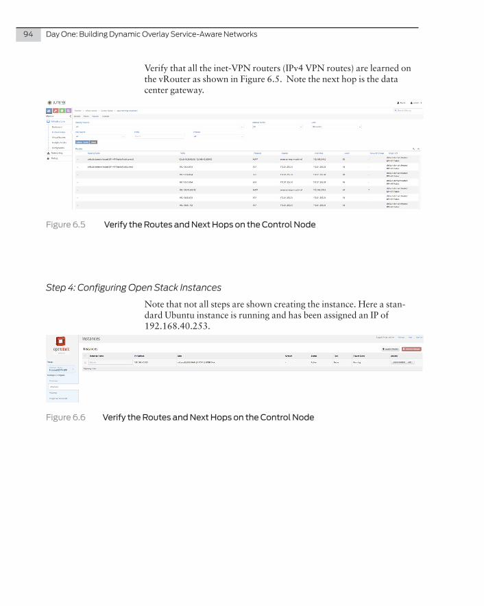
94 DayOne:BuildingDynamicOverlayService-AwareNetworks
Verify that all the inet-VPN routers (IPv4 VPN routes) are learned on the vRouter as shown in Figure 6.5. Note the next hop is the data center gateway.
Figure 6.5 Verify the Routes and Next Hops on the Control Node
Step 4: Configuring Open Stack Instances
Note that not all steps are shown creating the instance. Here a stan-dard Ubuntu instance is running and has been assigned an IP of 192.168.40.253.
Figure 6.6 Verify the Routes and Next Hops on the Control Node
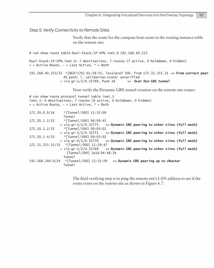
Chapter6:IntegratingVirtualizedServicesIntotheOverlayTopology 95
Step 5: Verify Connectivity to Remote Sites
Verify that the route for the compute host exists in the routing instance table on the remote site:
# run show route table Dual-Stack-IP-VPN.inet.0 192.168.40.253
Dual-Stack-IP-VPN.inet.0: 7 destinations, 7 routes (7 active, 0 holddown, 0 hidden)+ = Active Route, - = Last Active, * = Both
192.168.40.253/32 *[BGP/170] 01:28:55, localpref 100, from 172.31.255.31 << From correct peer AS path: ?, validation-state: unverified > via gr-1/2/0.32769, Push 18 << Over Dyn GRE tunnel
Now verify the Dynamic GRE tunnel creation on the remote site router:
# run show route protocol tunnel table inet.3 inet.3: 6 destinations, 7 routes (6 active, 0 holddown, 0 hidden)+ = Active Route, - = Last Active, * = Both
172.20.0.0/16 *[Tunnel/300] 11:32:09 Tunnel172.20.1.1/32 *[Tunnel/300] 08:09:45 > via gr-1/2/0.32773 << Dynamic GRE peering to other sites (full mesh)172.20.1.2/32 *[Tunnel/300] 09:03:01 > via gr-1/2/0.32771 << Dynamic GRE peering to other sites (full mesh)172.20.1.4/32 *[Tunnel/300] 09:03:02 > via gr-0/1/0.32770 << Dynamic GRE peering to other sites (full mesh)172.31.255.31/32 *[Tunnel/300] 11:29:47 > via gr-1/2/0.32769 << Dynamic GRE peering to other sites (full mesh) [Tunnel/300] 1w1d 04:48:34 Tunnel192.168.249.0/24 *[Tunnel/300] 11:32:09 << Dynamic GRE peering up to vRouter Tunnel
The final verifying step is to ping the remote site’s LAN address to see if the route exists on the remote site as shown in Figure 6.7.
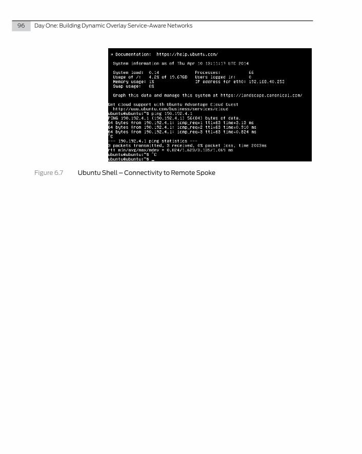
96 DayOne:BuildingDynamicOverlayService-AwareNetworks
Figure 6.7 Ubuntu Shell – Connectivity to Remote Spoke
Configuring DCI with VM Mobility Over IP with EVPN, with L3 Awareness
This chapter details the configuration for the DCI overlay solution using EVPN over GRE. For your convenience, Figure 6.3 is repeated here for your reference. Also, notes appear in boldface in the configurations themselves.
In your lab you’ll need the MX Series running Junos 14.1 or later.
This chapter is formatted so that an engineer or architect can follow the steps to configure the components in a logical manner, building the topology step-by-step per device as one would build out the network. The detail in the diagrams and the detailed configuration steps will allow a simple replication in a lab, or even replication to build out at scale.
All salient parts of the configuration of the data center routers is shown, along with the verification from the remote routers; omitted are network management elements, such as AAA, SNMP.
NOTE This book’s configurations are also available in a Cut and Paste Edition, essentially an .rtf file that you can use to cut and paste configurations into your lab devices. See this book’s landing page at www.juniper.net/dayone.
Chapter 7
DCI Use Case with VM Mobility Over IP with EVPN and Layer 3 (IP) Awareness (Junos 14.1)

98 DayOne:BuildingDynamicOverlayService-AwareNetworks
Branch 1 - MX
Ethernet
Private Core
Lo0172.20.1.1
OSPF OSPF
(L3 Transport)Core
Protocol
BGP Peering uses loopback addresses - MPLS over GRE data traffic is encapsulated in the GRE header (source and destination == loopback addfresses
Tunneled/Private Protocol
Remote Site Dynamic GRE Tunnel
MP-BGP PeeringL2 ServiceIPv6 VPNIPv4 VPN
Branch 2 - M7i
Private Core
Lo0172.20.1.2
Private Core
Lo0172.20.1.3
inet.0
inet.0
Private IP or L2 BB
inet.0
lo0.0 172.31.255.31
Branch 3 - M7i
VPLS1
VPLS1
VPLS1
L2 ServiceIPv6 VPNIPv4 VPN
L2 ServiceIPv6 VPNIPv4 VPN
vRouter
Ubuntu
DC L3 Fabric
inet.0Dual-Stack-IP-
VPN Dual-Stack-IP-
VPN
Dual-Stack-IP-VPN
Dual-Stack-IP-VPN
lo0.0 172.20.1.4
EVPN
inet.0
Dual-Stack-IP-VPN
DCI EVPN Dynamic GRE Tunnel
VPLS1
DC L2 Fabric
EVPN
VPLS1DC L2 Fabric
IRB Associated with EVPN
EVPNVirtual Switch
Bridge Domain 809
EVPNVirtual Switch
Bridge Domain 809
VPLSVLAN 805
VPLSVLAN 805
DC 1
DC 2
DCI
Figure 7.1 Detailed Topology of VM Mobility over IP
Figure 7.1 illustrates the topology tested in this example, and it is, in effect, the same topology as used in the overlay case without encryp-tion (although the encryption topology can be used as well). As detailed in the diagram there are two DC routers and each has the same EVPN instance configured, along with an IP VPN (Dual-Stack-IP-VPN), of which the IRB interface is member. Additionally there is a VPLS instance remaining from the previous examples – thus illustrat-ing VPLS and EVPN can coexist. All other routers are L3 adjacent – these routers are used to check the /32 route advertisement. Again we are working over a Dynamic GRE-tunneled topology —since that is the focus of this book – however in ususal circumstances the core is an IP MPLS core.
Chapter7:DCIUseCasewithVMMobilityOverIPwithEVPNandLayer3(IP)Awareness 99
Step 1: Configure the Interfaces on Datacenter 1
First, configure the IP core-facing interface:
ge-1/0/0 { vlan-tagging; unit 0 { vlan-id 101; family inet { address 10.10.10.5/24; } }}
Then configure the VLAN (data center-facing) interfaces:
ge-1/0/2 { flexible-vlan-tagging; mtu 9000; encapsulation flexible-ethernet-services; unit 6 { family bridge { << Configured as a bridge (member of a bridge domain) interface-mode trunk; vlan-id-list 809; vlan-rewrite { << Re-write is used in this testing TOR VLAN in this DC is 808 translate 808 809; } } }}irb { << IRB interface will make this topology L3 aware unit 809 { family inet { address 192.168.7.2/24; } }}lo0 { unit 0 { family inet { address 172.20.1.4/32 { << Loopback used primary; preferred; } } family inet6; family mpls; }}
100 DayOne:BuildingDynamicOverlayService-AwareNetworks
Step 2: Configure the Routing Protocols on Datacenter 1
Configure OSPF for core-facing interfaces for BGP Peering and GRE overlay:
ospf { area 0.0.0.0 { interface ge-1/0/0.0; interface lo0.0; }}
Configure protocols for MPLS and IPv6 forwarding along with BGP groups for EVPN peering:
mpls { ipv6-tunneling; interface lo0.0;}bgp { group iBGP-Overlay-Peers { type internal; local-address 172.20.1.4; family inet-vpn { << Used for IP VPN IRB L3 Unification unicast; } family inet6-vpn { << Not used in EVPN use case but enabled in this case unicast; } family l2vpn { auto-discovery-only; signaling; } family evpn { << Configured for EVPN signaling signaling; } bfd-liveness-detection { minimum-interval 1000; multiplier 3; } neighbor 172.31.255.31; << Configured explicit BGP Peer (the RR) }}
Now, configure the Dynamic GRE interface:
dynamic-tunnels { Dynamic-Overlay { source-address 172.20.1.4; gre; destination-networks { 172.31.255.31/32; 172.20.0.0/16; 192.168.249.0/24; } } }
Chapter7:DCIUseCasewithVMMobilityOverIPwithEVPNandLayer3(IP)Awareness 101
Enable tunneling services and EVPN Composite Next Hop:
forwarding-table { chained-composite-next-hop { ingress { evpn; } } }
chassis { fpc 1 { pic 0 { tunnel-services { bandwidth 1g; } } }}
Step 3: Configure the Routing Protocols on Datacenter 1
Configure router-ID, AS, and RD:
router-id 172.20.1.4; route-distinguisher-id 172.20.1.4; autonomous-system 64512;
Configure routing instances for Layer 2 and Layer 3:
NOTE In the current EVPN implementation the IRB must be a member of a Layer 3 VPN.
Dual-Stack-IP-VPN { << This is the IP VPN associated with the EVPN instance instance-type vrf; interface irb.809; << Add IRB to the L3 VPN interface lo0.1; vrf-target target:100:2; vrf-table-label; routing-options { router-id 172.20.1.4; }}EVPN { instance-type virtual-switch; interface ge-1/0/2.6; << Trunk interface
102 DayOne:BuildingDynamicOverlayService-AwareNetworks
route-distinguisher 64512:7; vrf-target target:64512:200; protocols { evpn { << EVPN Configuration label-allocation per-instance; extended-vlan-list 809; << Allow VLAN 809 for EVPN extension } } bridge-domains { << This bridge domain is a member of The VS VLAN809 { domain-type bridge; vlan-id 809; routing-interface irb.809; << Assign IRB to this bridge domain } }}
Step 4: Configure the Interfaces on Data Center 2
Configure IP core-facing interface (note this is same router from the previous examples):
ge-1/0/1 { flexible-vlan-tagging; encapsulation flexible-ethernet-services; unit 0 { vlan-id 1; family inet { address 172.16.32.10/30; } } unit 1 { vlan-id 2; family inet { address 172.16.33.2/30; } }}ge-1/0/3 { unit 0 { family inet { address 172.16.40.1/30; } }}ge-1/0/7 { unit 0 { family inet { address 20.20.20.2/24; } }}
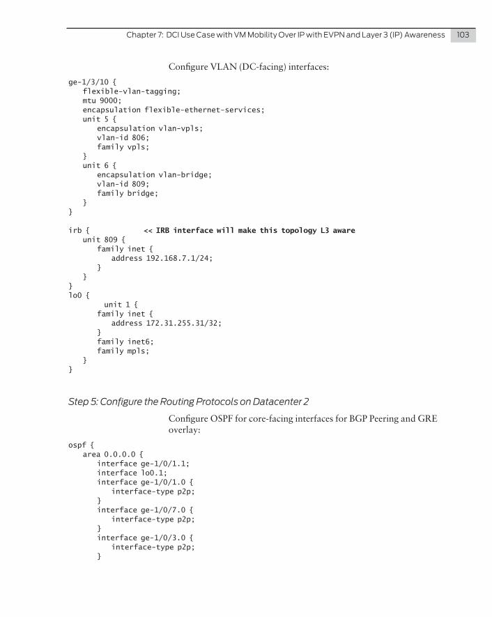
Chapter7:DCIUseCasewithVMMobilityOverIPwithEVPNandLayer3(IP)Awareness 103
Configure VLAN (DC-facing) interfaces:
ge-1/3/10 { flexible-vlan-tagging; mtu 9000; encapsulation flexible-ethernet-services; unit 5 { encapsulation vlan-vpls; vlan-id 806; family vpls; } unit 6 { encapsulation vlan-bridge; vlan-id 809; family bridge; }}
irb { << IRB interface will make this topology L3 aware unit 809 { family inet { address 192.168.7.1/24; } }}lo0 { unit 1 { family inet { address 172.31.255.31/32; } family inet6; family mpls; }}
Step 5: Configure the Routing Protocols on Datacenter 2
Configure OSPF for core-facing interfaces for BGP Peering and GRE overlay:
ospf { area 0.0.0.0 { interface ge-1/0/1.1; interface lo0.1; interface ge-1/0/1.0 { interface-type p2p; } interface ge-1/0/7.0 { interface-type p2p; } interface ge-1/0/3.0 { interface-type p2p; }
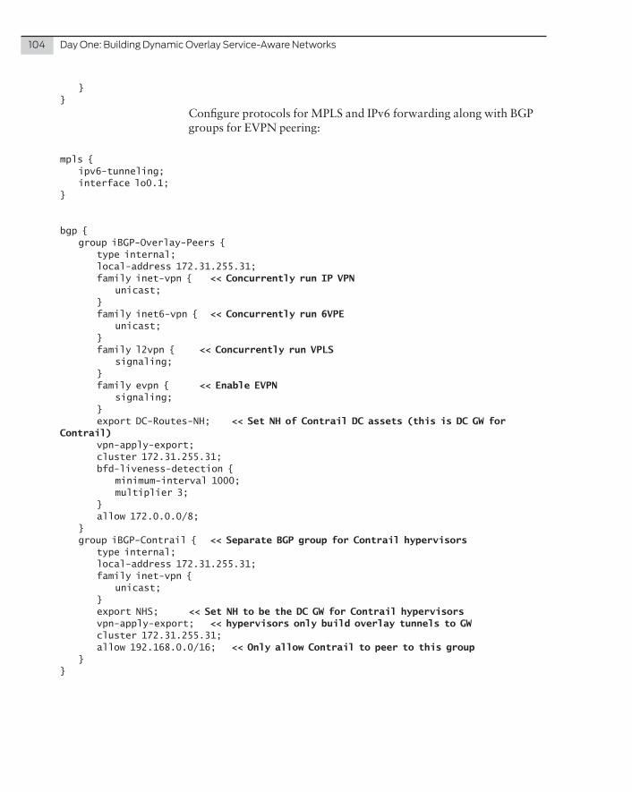
104 DayOne:BuildingDynamicOverlayService-AwareNetworks
}}
Configure protocols for MPLS and IPv6 forwarding along with BGP groups for EVPN peering:
mpls { ipv6-tunneling; interface lo0.1;}
bgp { group iBGP-Overlay-Peers { type internal; local-address 172.31.255.31; family inet-vpn { << Concurrently run IP VPN unicast; } family inet6-vpn { << Concurrently run 6VPE unicast; } family l2vpn { << Concurrently run VPLS signaling; } family evpn { << Enable EVPN signaling; } export DC-Routes-NH; << Set NH of Contrail DC assets (this is DC GW for Contrail) vpn-apply-export; cluster 172.31.255.31; bfd-liveness-detection { minimum-interval 1000; multiplier 3; } allow 172.0.0.0/8; } group iBGP-Contrail { << Separate BGP group for Contrail hypervisors type internal; local-address 172.31.255.31; family inet-vpn { unicast; } export NHS; << Set NH to be the DC GW for Contrail hypervisors vpn-apply-export; << hypervisors only build overlay tunnels to GW cluster 172.31.255.31; allow 192.168.0.0/16; << Only allow Contrail to peer to this group }}

Chapter7:DCIUseCasewithVMMobilityOverIPwithEVPNandLayer3(IP)Awareness 105
Configure the Dynamic GRE interface:
dynamic-tunnels { Dynamic-Overlay { source-address 172.31.255.31; gre; destination-networks { 192.168.240.0/24; 172.20.0.0/16; 192.168.249.0/24; } }}
Enable tunneling services and EVPN composite next hop. This is required to ensure the PE advertises and uses the MAC+IP binding the EVPN table. Without this statement the host routes will not be advertised or used:
forwarding-table { chained-composite-next-hop { ingress { evpn; } } }
chassis { fpc 1 { pic 0 { tunnel-services { bandwidth 1g; } } }}chassis {network-services enhanced-ip;
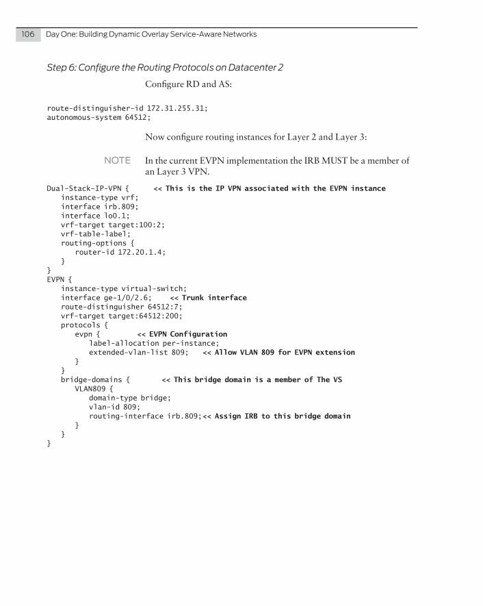
106 DayOne:BuildingDynamicOverlayService-AwareNetworks
Step 6: Configure the Routing Protocols on Datacenter 2
Configure RD and AS:
route-distinguisher-id 172.31.255.31;autonomous-system 64512;
Now configure routing instances for Layer 2 and Layer 3:
NOTE In the current EVPN implementation the IRB MUST be a member of an Layer 3 VPN.
Dual-Stack-IP-VPN { << This is the IP VPN associated with the EVPN instance instance-type vrf; interface irb.809; interface lo0.1; vrf-target target:100:2; vrf-table-label; routing-options { router-id 172.20.1.4; }}EVPN { instance-type virtual-switch; interface ge-1/0/2.6; << Trunk interface route-distinguisher 64512:7; vrf-target target:64512:200; protocols { evpn { << EVPN Configuration label-allocation per-instance; extended-vlan-list 809; << Allow VLAN 809 for EVPN extension } } bridge-domains { << This bridge domain is a member of The VS VLAN809 { domain-type bridge; vlan-id 809; routing-interface irb.809; << Assign IRB to this bridge domain } }}
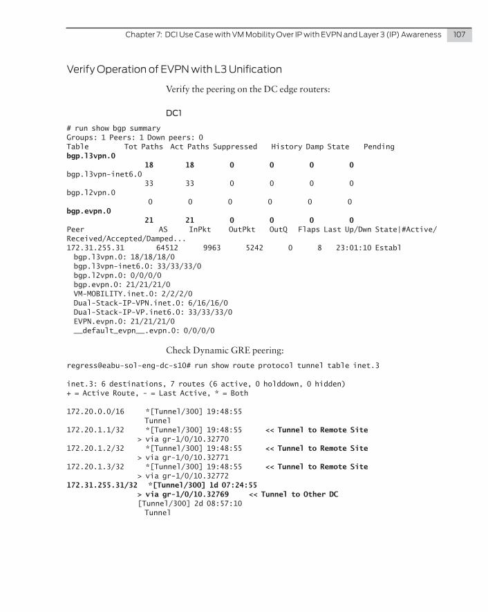
Chapter7:DCIUseCasewithVMMobilityOverIPwithEVPNandLayer3(IP)Awareness 107
VerifyOperationofEVPNwithL3Unification
Verify the peering on the DC edge routers:
DC1
# run show bgp summary Groups: 1 Peers: 1 Down peers: 0Table Tot Paths Act Paths Suppressed History Damp State Pendingbgp.l3vpn.0 18 18 0 0 0 0bgp.l3vpn-inet6.0 33 33 0 0 0 0bgp.l2vpn.0 0 0 0 0 0 0bgp.evpn.0 21 21 0 0 0 0Peer AS InPkt OutPkt OutQ Flaps Last Up/Dwn State|#Active/Received/Accepted/Damped...172.31.255.31 64512 9963 5242 0 8 23:01:10 Establ bgp.l3vpn.0: 18/18/18/0 bgp.l3vpn-inet6.0: 33/33/33/0 bgp.l2vpn.0: 0/0/0/0 bgp.evpn.0: 21/21/21/0 VM-MOBILITY.inet.0: 2/2/2/0 Dual-Stack-IP-VPN.inet.0: 6/16/16/0 Dual-Stack-IP-VP.inet6.0: 33/33/33/0 EVPN.evpn.0: 21/21/21/0 __default_evpn__.evpn.0: 0/0/0/0
Check Dynamic GRE peering:
regress@eabu-sol-eng-dc-s10# run show route protocol tunnel table inet.3
inet.3: 6 destinations, 7 routes (6 active, 0 holddown, 0 hidden)+ = Active Route, - = Last Active, * = Both
172.20.0.0/16 *[Tunnel/300] 19:48:55 Tunnel172.20.1.1/32 *[Tunnel/300] 19:48:55 << Tunnel to Remote Site > via gr-1/0/10.32770172.20.1.2/32 *[Tunnel/300] 19:48:55 << Tunnel to Remote Site > via gr-1/0/10.32771172.20.1.3/32 *[Tunnel/300] 19:48:55 << Tunnel to Remote Site > via gr-1/0/10.32772172.31.255.31/32 *[Tunnel/300] 1d 07:24:55 > via gr-1/0/10.32769 << Tunnel to Other DC [Tunnel/300] 2d 08:57:10 Tunnel

108 DayOne:BuildingDynamicOverlayService-AwareNetworks
DC2
Note this is the RR for the WAN remote sites, so you see peers to the WAN and to the Contrail hypervisors. Data center peer is highlighted:
# run show bgp summary Groups: 3 Peers: 6 Down peers: 0Unconfigured peers: 5Table Tot Paths Act Paths Suppressed History Damp State Pendingbgp.l3vpn.0 295 295 0 0 0 0bgp.l3vpn-inet6.0 22 22 0 0 0 0bgp.l2vpn.0 3 3 0 0 0 0bgp.evpn.0 23 23 0 0 0 0Peer AS InPkt OutPkt OutQ Flaps Last Up/Dwn State|#Active/Received/Accepted/Damped...172.20.1.1 64512 3067 3132 0 0 23:02:26 Establ bgp.l3vpn.0: 52/52/52/0 bgp.l3vpn-inet6.0: 11/11/11/0 bgp.l2vpn.0: 1/1/1/0 Dual-Stack-IP-VP.inet6.0: 11/11/11/0 CONT.inet.0: 51/51/51/0 Dual-Stack-IP-VPN.inet.0: 1/1/1/0 vpls1.l2vpn.0: 1/1/1/0172.20.1.2 64512 1011 1005 0 0 7:29:24 Establ bgp.l3vpn.0: 206/206/206/0 bgp.l2vpn.0: 1/1/1/0 CONT.inet.0: 204/204/204/0 Dual-Stack-IP-VPN.inet.0: 2/2/2/0 vpls1.l2vpn.0: 1/1/1/0172.20.1.3 64512 3069 3133 0 0 23:02:26 Establ bgp.l3vpn.0: 4/4/4/0 bgp.l3vpn-inet6.0: 11/11/11/0 bgp.l2vpn.0: 1/1/1/0 Dual-Stack-IP-VP.inet6.0: 11/11/11/0 CONT.inet.0: 3/3/3/0 Dual-Stack-IP-VPN.inet.0: 1/1/1/0 vpls1.l2vpn.0: 1/1/1/0172.20.1.4 64512 3103 3140 0 0 23:02:26 Establ bgp.l3vpn.0: 16/16/16/0 bgp.l3vpn-inet6.0: 0/0/0/0 bgp.l2vpn.0: 0/0/0/0 bgp.evpn.0: 23/23/23/0 Dual-Stack-IP-VPN.inet.0: 3/14/14/0 VM-MOBILITY.inet.0: 2/2/2/0 vpls1.l2vpn.0: 0/0/0/0 EVPN.evpn.0: 23/23/23/0 __default_evpn__.evpn.0: 23/23/23/0192.168.249.2 64512 2845 3247 0 0 23:29:09 Establ bgp.l3vpn.0: 17/17/17/0 Dual-Stack-IP-VPN.inet.0: 1/1/1/0
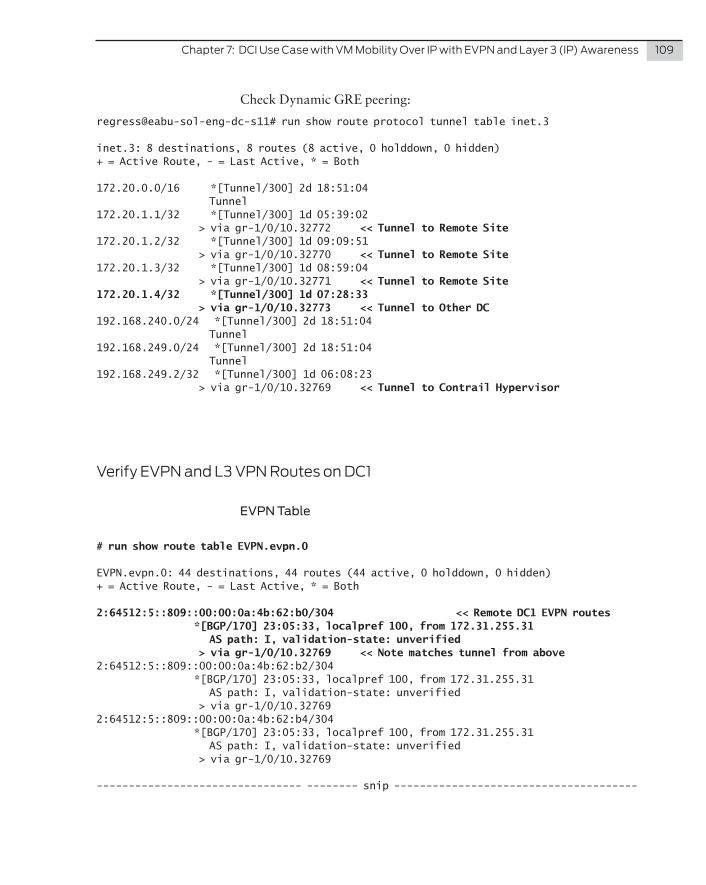
Chapter7:DCIUseCasewithVMMobilityOverIPwithEVPNandLayer3(IP)Awareness 109
Check Dynamic GRE peering:
regress@eabu-sol-eng-dc-s11# run show route protocol tunnel table inet.3
inet.3: 8 destinations, 8 routes (8 active, 0 holddown, 0 hidden)+ = Active Route, - = Last Active, * = Both
172.20.0.0/16 *[Tunnel/300] 2d 18:51:04 Tunnel172.20.1.1/32 *[Tunnel/300] 1d 05:39:02 > via gr-1/0/10.32772 << Tunnel to Remote Site172.20.1.2/32 *[Tunnel/300] 1d 09:09:51 > via gr-1/0/10.32770 << Tunnel to Remote Site172.20.1.3/32 *[Tunnel/300] 1d 08:59:04 > via gr-1/0/10.32771 << Tunnel to Remote Site172.20.1.4/32 *[Tunnel/300] 1d 07:28:33 > via gr-1/0/10.32773 << Tunnel to Other DC192.168.240.0/24 *[Tunnel/300] 2d 18:51:04 Tunnel192.168.249.0/24 *[Tunnel/300] 2d 18:51:04 Tunnel192.168.249.2/32 *[Tunnel/300] 1d 06:08:23 > via gr-1/0/10.32769 << Tunnel to Contrail Hypervisor
VerifyEVPNandL3VPNRoutesonDC1
EVPN Table
# run show route table EVPN.evpn.0
EVPN.evpn.0: 44 destinations, 44 routes (44 active, 0 holddown, 0 hidden)+ = Active Route, - = Last Active, * = Both
2:64512:5::809::00:00:0a:4b:62:b0/304 << Remote DC1 EVPN routes *[BGP/170] 23:05:33, localpref 100, from 172.31.255.31 AS path: I, validation-state: unverified > via gr-1/0/10.32769 << Note matches tunnel from above2:64512:5::809::00:00:0a:4b:62:b2/304 *[BGP/170] 23:05:33, localpref 100, from 172.31.255.31 AS path: I, validation-state: unverified > via gr-1/0/10.327692:64512:5::809::00:00:0a:4b:62:b4/304 *[BGP/170] 23:05:33, localpref 100, from 172.31.255.31 AS path: I, validation-state: unverified > via gr-1/0/10.32769
-------------------------------- -------- snip --------------------------------------
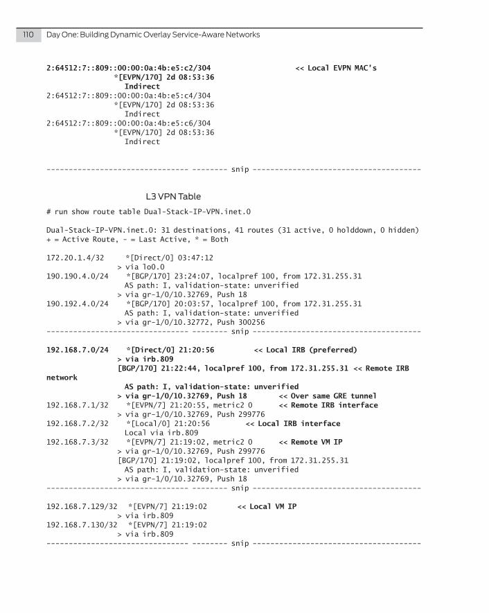
110 DayOne:BuildingDynamicOverlayService-AwareNetworks
2:64512:7::809::00:00:0a:4b:e5:c2/304 << Local EVPN MAC’s *[EVPN/170] 2d 08:53:36 Indirect2:64512:7::809::00:00:0a:4b:e5:c4/304 *[EVPN/170] 2d 08:53:36 Indirect2:64512:7::809::00:00:0a:4b:e5:c6/304 *[EVPN/170] 2d 08:53:36 Indirect
-------------------------------- -------- snip --------------------------------------
L3 VPN Table
# run show route table Dual-Stack-IP-VPN.inet.0
Dual-Stack-IP-VPN.inet.0: 31 destinations, 41 routes (31 active, 0 holddown, 0 hidden)+ = Active Route, - = Last Active, * = Both
172.20.1.4/32 *[Direct/0] 03:47:12 > via lo0.0190.190.4.0/24 *[BGP/170] 23:24:07, localpref 100, from 172.31.255.31 AS path: I, validation-state: unverified > via gr-1/0/10.32769, Push 18190.192.4.0/24 *[BGP/170] 20:03:57, localpref 100, from 172.31.255.31 AS path: I, validation-state: unverified > via gr-1/0/10.32772, Push 300256-------------------------------- -------- snip --------------------------------------
192.168.7.0/24 *[Direct/0] 21:20:56 << Local IRB (preferred) > via irb.809 [BGP/170] 21:22:44, localpref 100, from 172.31.255.31 << Remote IRB network AS path: I, validation-state: unverified > via gr-1/0/10.32769, Push 18 << Over same GRE tunnel192.168.7.1/32 *[EVPN/7] 21:20:55, metric2 0 << Remote IRB interface > via gr-1/0/10.32769, Push 299776192.168.7.2/32 *[Local/0] 21:20:56 << Local IRB interface Local via irb.809192.168.7.3/32 *[EVPN/7] 21:19:02, metric2 0 << Remote VM IP > via gr-1/0/10.32769, Push 299776 [BGP/170] 21:19:02, localpref 100, from 172.31.255.31 AS path: I, validation-state: unverified > via gr-1/0/10.32769, Push 18-------------------------------- -------- snip --------------------------------------
192.168.7.129/32 *[EVPN/7] 21:19:02 << Local VM IP > via irb.809192.168.7.130/32 *[EVPN/7] 21:19:02 > via irb.809-------------------------------- -------- snip --------------------------------------
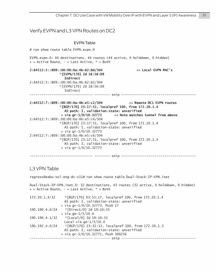
Chapter7:DCIUseCasewithVMMobilityOverIPwithEVPNandLayer3(IP)Awareness 111
VerifyEVPNandL3VPNRoutesonDC2
EVPN Table
# run show route table EVPN.evpn.0
EVPN.evpn.0: 44 destinations, 44 routes (44 active, 0 holddown, 0 hidden)+ = Active Route, - = Last Active, * = Both
2:64512:5::809::00:00:0a:4b:62:b0/304 << Local EVPN MAC’s *[EVPN/170] 2d 18:56:09 Indirect2:64512:5::809::00:00:0a:4b:62:b2/304 *[EVPN/170] 2d 18:56:09 Indirect-------------------------------- -------- snip --------------------------------------
2:64512:7::809::00:00:0a:4b:e5:c2/304 << Remote DC1 EVPN routes *[BGP/170] 23:17:51, localpref 100, from 172.20.1.4 AS path: I, validation-state: unverified > via gr-1/0/10.32773 << Note matches tunnel from above2:64512:7::809::00:00:0a:4b:e5:c4/304 *[BGP/170] 23:17:51, localpref 100, from 172.20.1.4 AS path: I, validation-state: unverified > via gr-1/0/10.327732:64512:7::809::00:00:0a:4b:e5:c6/304 *[BGP/170] 23:17:51, localpref 100, from 172.20.1.4 AS path: I, validation-state: unverified > via gr-1/0/10.32773
-------------------------------- -------- snip --------------------------------------
L3VPNTable
regress@eabu-sol-eng-dc-s11# run show route table Dual-Stack-IP-VPN.inet
Dual-Stack-IP-VPN.inet.0: 32 destinations, 43 routes (32 active, 0 holddown, 0 hidden)+ = Active Route, - = Last Active, * = Both
172.20.1.4/32 *[BGP/170] 03:55:17, localpref 100, from 172.20.1.4 AS path: I, validation-state: unverified > via gr-1/0/10.32773, Push 17190.190.4.0/24 *[Direct/0] 2d 19:10:33 > via ge-1/3/10.4190.190.4.1/32 *[Local/0] 2d 19:10:33 Local via ge-1/3/10.4190.192.4.0/24 *[BGP/170] 23:32:12, localpref 100, from 172.20.1.3 AS path: I, validation-state: unverified > via gr-1/0/10.32771, Push 300256-------------------------------- -------- snip --------------------------------------
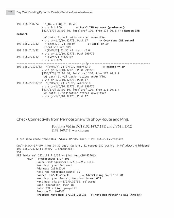
112 DayOne:BuildingDynamicOverlayService-AwareNetworks
192.168.7.0/24 *[Direct/0] 21:30:49 > via irb.809 << Local IRB network (preferred) [BGP/170] 21:09:30, localpref 100, from 172.20.1.4 << Remote IRB network AS path: I, validation-state: unverified > via gr-1/0/10.32773, Push 17 << Over same GRE tunnel192.168.7.1/32 *[Local/0] 21:30:49 << Local VM IP Local via irb.809192.168.7.2/32 *[EVPN/7] 21:30:49, metric2 0 > via gr-1/0/10.32773, Push 299776192.168.7.3/32 *[EVPN/7] 21:27:07 > via irb.809-------------------------------- -------- snip --------------------------------------192.168.7.129/32 *[EVPN/7] 21:27:07, metric2 0 << Remote VM IP > via gr-1/0/10.32773, Push 299776 [BGP/170] 21:09:30, localpref 100, from 172.20.1.4 AS path: I, validation-state: unverified > via gr-1/0/10.32773, Push 17192.168.7.130/32 *[EVPN/7] 21:27:07, metric2 0 > via gr-1/0/10.32773, Push 299776 [BGP/170] 21:09:30, localpref 100, from 172.20.1.4 AS path: I, validation-state: unverified > via gr-1/0/10.32773, Push 17
CheckConnectivityfromRemoteSitewithShowRouteandPing.
For this a VM in DC1 (192.168.7.131) and a VM in DC2 (192.168.7.3) was chosen:
# run show route table Dual-Stack-IP-VPN.inet.0 192.168.7.3 extensive
Dual-Stack-IP-VPN.inet.0: 30 destinations, 31 routes (30 active, 0 holddown, 0 hidden)192.168.7.3/32 (1 entry, 1 announced)TSI:KRT in-kernel 192.168.7.3/32 -> {indirect(1048576)} *BGP Preference: 170/-101 Route Distinguisher: 172.31.255.31:11 Next hop type: Indirect Address: 0x93c63b0 Next-hop reference count: 35 Source: 172.31.255.31 << Advertising router is RR Next hop type: Router, Next hop index: 605 Next hop: via gr-1/2/0.32769, selected Label operation: Push 18 Label TTL action: prop-ttl Session Id: 0xd002 Protocol next hop: 172.31.255.31 << Next Hop router is DC2 (the RR)
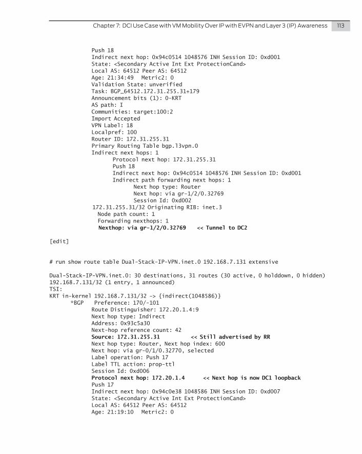
Chapter7:DCIUseCasewithVMMobilityOverIPwithEVPNandLayer3(IP)Awareness 113
Push 18 Indirect next hop: 0x94c0514 1048576 INH Session ID: 0xd001 State: <Secondary Active Int Ext ProtectionCand> Local AS: 64512 Peer AS: 64512 Age: 21:34:49 Metric2: 0 Validation State: unverified Task: BGP_64512.172.31.255.31+179 Announcement bits (1): 0-KRT AS path: I Communities: target:100:2 Import Accepted VPN Label: 18 Localpref: 100 Router ID: 172.31.255.31 Primary Routing Table bgp.l3vpn.0 Indirect next hops: 1 Protocol next hop: 172.31.255.31 Push 18 Indirect next hop: 0x94c0514 1048576 INH Session ID: 0xd001 Indirect path forwarding next hops: 1 Next hop type: Router Next hop: via gr-1/2/0.32769 Session Id: 0xd002 172.31.255.31/32 Originating RIB: inet.3 Node path count: 1 Forwarding nexthops: 1 Nexthop: via gr-1/2/0.32769 << Tunnel to DC2
[edit]
# run show route table Dual-Stack-IP-VPN.inet.0 192.168.7.131 extensive
Dual-Stack-IP-VPN.inet.0: 30 destinations, 31 routes (30 active, 0 holddown, 0 hidden)192.168.7.131/32 (1 entry, 1 announced)TSI:KRT in-kernel 192.168.7.131/32 -> {indirect(1048586)} *BGP Preference: 170/-101 Route Distinguisher: 172.20.1.4:9 Next hop type: Indirect Address: 0x93c5a30 Next-hop reference count: 42 Source: 172.31.255.31 << Still advertised by RR Next hop type: Router, Next hop index: 600 Next hop: via gr-0/1/0.32770, selected Label operation: Push 17 Label TTL action: prop-ttl Session Id: 0xd006 Protocol next hop: 172.20.1.4 << Next hop is now DC1 loopback Push 17 Indirect next hop: 0x94c0e38 1048586 INH Session ID: 0xd007 State: <Secondary Active Int Ext ProtectionCand> Local AS: 64512 Peer AS: 64512 Age: 21:19:10 Metric2: 0
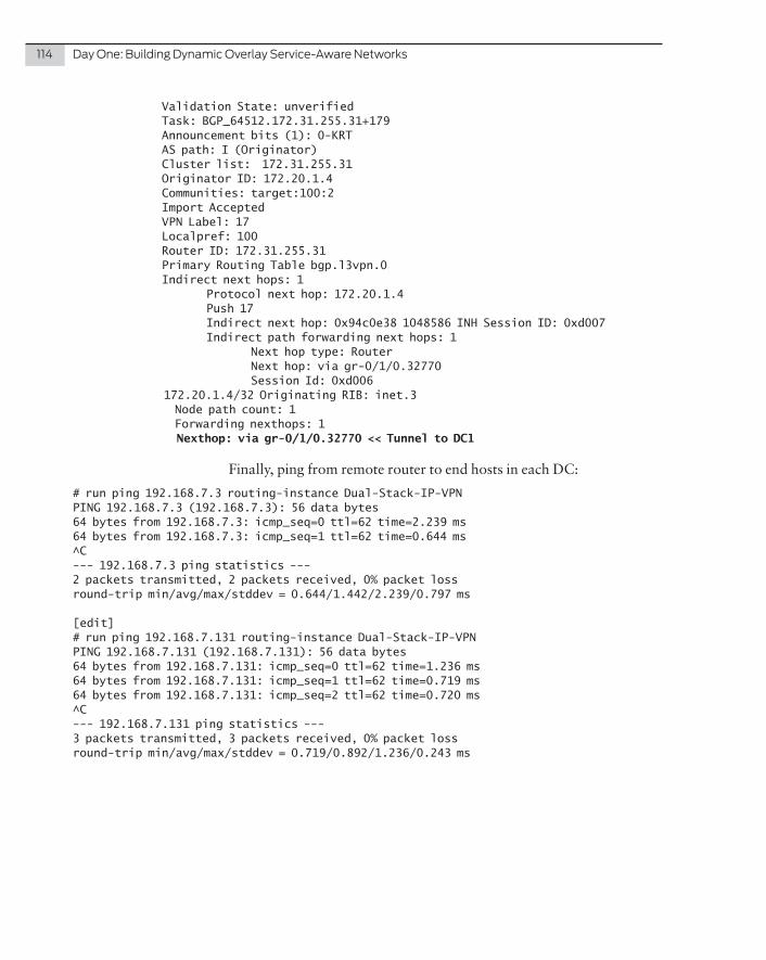
114 DayOne:BuildingDynamicOverlayService-AwareNetworks
Validation State: unverified Task: BGP_64512.172.31.255.31+179 Announcement bits (1): 0-KRT AS path: I (Originator) Cluster list: 172.31.255.31 Originator ID: 172.20.1.4 Communities: target:100:2 Import Accepted VPN Label: 17 Localpref: 100 Router ID: 172.31.255.31 Primary Routing Table bgp.l3vpn.0 Indirect next hops: 1 Protocol next hop: 172.20.1.4 Push 17 Indirect next hop: 0x94c0e38 1048586 INH Session ID: 0xd007 Indirect path forwarding next hops: 1 Next hop type: Router Next hop: via gr-0/1/0.32770 Session Id: 0xd006 172.20.1.4/32 Originating RIB: inet.3 Node path count: 1 Forwarding nexthops: 1 Nexthop: via gr-0/1/0.32770 << Tunnel to DC1
Finally, ping from remote router to end hosts in each DC:
# run ping 192.168.7.3 routing-instance Dual-Stack-IP-VPN PING 192.168.7.3 (192.168.7.3): 56 data bytes64 bytes from 192.168.7.3: icmp_seq=0 ttl=62 time=2.239 ms64 bytes from 192.168.7.3: icmp_seq=1 ttl=62 time=0.644 ms^C--- 192.168.7.3 ping statistics ---2 packets transmitted, 2 packets received, 0% packet lossround-trip min/avg/max/stddev = 0.644/1.442/2.239/0.797 ms
[edit]# run ping 192.168.7.131 routing-instance Dual-Stack-IP-VPN PING 192.168.7.131 (192.168.7.131): 56 data bytes64 bytes from 192.168.7.131: icmp_seq=0 ttl=62 time=1.236 ms64 bytes from 192.168.7.131: icmp_seq=1 ttl=62 time=0.719 ms64 bytes from 192.168.7.131: icmp_seq=2 ttl=62 time=0.720 ms^C--- 192.168.7.131 ping statistics ---3 packets transmitted, 3 packets received, 0% packet lossround-trip min/avg/max/stddev = 0.719/0.892/1.236/0.243 ms