Embed Size (px)
Citation preview

Day 7: Review lecture
Reminders/Updates:HW3 in/ HW4 out
Thurs: Exam 1, in classBring pencil, calculator, 3x5” formula card
Revisiting What We Know…

Exam mechanics
• 1 hr long• In class G125, 11am prompt!• 1 3x5 handwritten formula card• Pencil• Calculator – (non-internet connectable device)• Do not cheat. It’s the surest way to piss me off
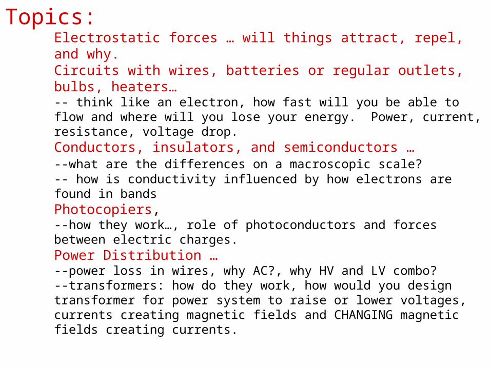
Topics:Electrostatic forces … will things attract, repel, and why.
Circuits with wires, batteries or regular outlets, bulbs, heaters… -- think like an electron, how fast will you be able to flow and where will you lose your energy. Power, current, resistance, voltage drop. Conductors, insulators, and semiconductors … --what are the differences on a macroscopic scale? -- how is conductivity influenced by how electrons are found in bandsPhotocopiers, --how they work…, role of photoconductors and forces between electric charges.Power Distribution … --power loss in wires, why AC?, why HV and LV combo? --transformers: how do they work, how would you design transformer for power system to raise or lower voltages, currents creating magnetic fields and CHANGING magnetic fields creating currents.
Review in reverse order today.Power / TransformersEnergy Bands / Insulators, Conductors, Photoconductors.Electric circuits
4
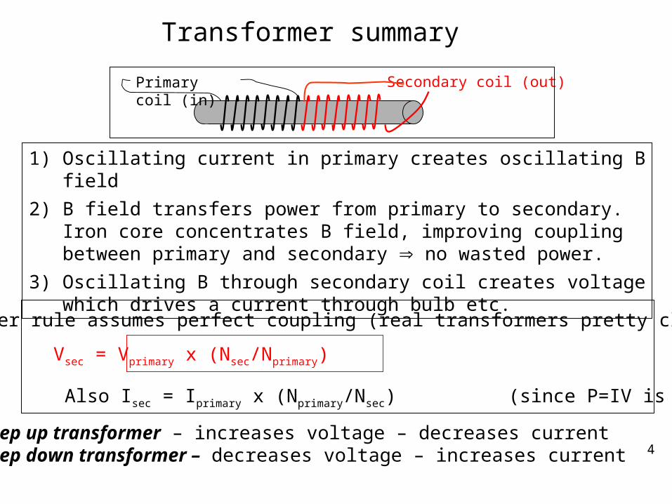
1) Oscillating current in primary creates oscillating B field
2) B field transfers power from primary to secondary. Iron core concentrates B field, improving coupling between primary and secondary no wasted power.
3) Oscillating B through secondary coil creates voltage which drives a current through bulb etc.
step up transformer – increases voltage – decreases currentstep down transformer – decreases voltage – increases current
Transformer summary
Transformer rule assumes perfect coupling (real transformers pretty close)
Vsec = Vprimary x (Nsec/Nprimary)
Also Isec = Iprimary x (Nprimary/Nsec) (since P=IV is constant)
Secondary coil (out)Primary coil (in)
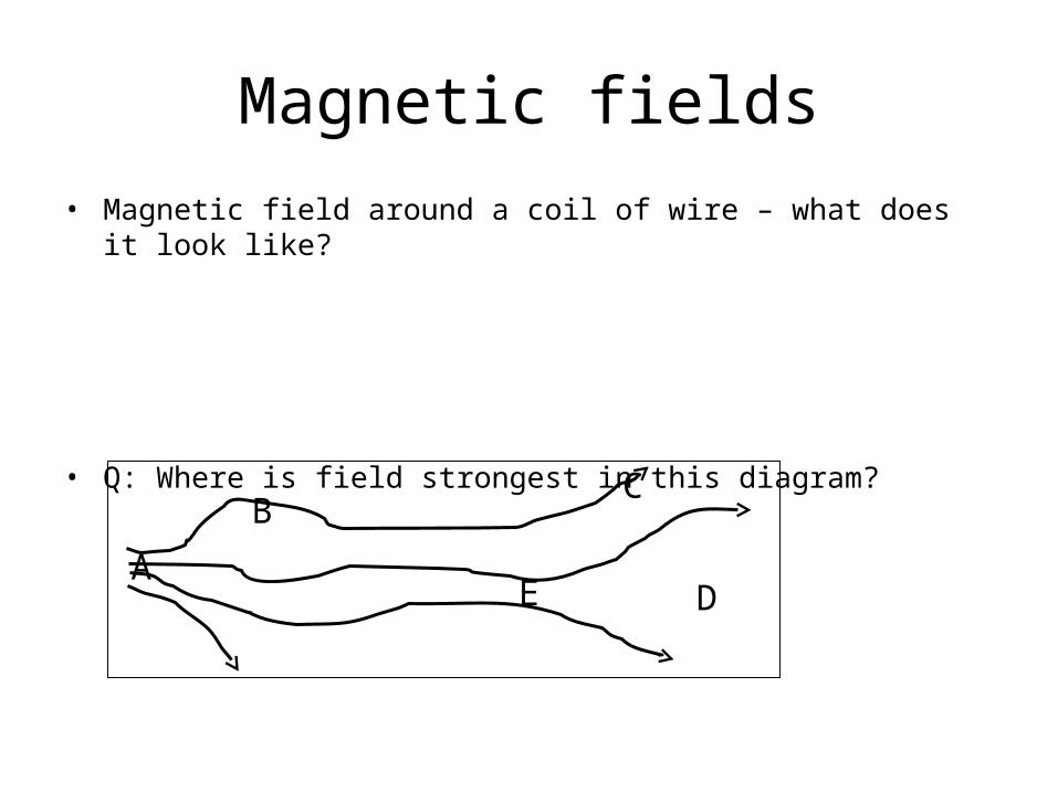
Magnetic fields
• Magnetic field around a coil of wire – what does it look like?
• Q: Where is field strongest in this diagram?
A
BC
DE

current out
Q: What happens if current oscillates in primary but there is no core?
a. The light bulb will not light because there is no conduction path for electrons to move from one coil to another.
b. The light bulb will not light because there is no changing magnetic field present. c. The light bulb will be dimmer than with a core.d. The light bulb will be the same brightness as with core.e. The light bulb will be brighter than with core.
current in
NOTE: Not everything curly is a transformer; e.g. lightbulb filament is NOT.
Transformer construction detail. The core.

Which would make the best core for a transformer if strength did not matter?a.wood, b. copper, c. glass, d. iron wrapped in plastic insulator
If I took a transformer used to convert 100 V up to 1000 V and I hooked the primary up to a 12 V car battery. If I then went to measure the voltage across the secondary coil, what would I find?a. 0 V, b. 12 V, c. 1200 V. d. 120 V, e. 1.2 V
What is ratio of turns on primary to secondary? a. 10 pri. to 1 sec., b. 1 to 10, c. 100 to 1, d. 1000 to 1, e. 1 to 1000
Transformer questions

power plant
5000V
500,000 V (on towers)substation
5000 Vrunning around town.
120 Vshort wiresinto houses
Power distribution system
Why do we transmit power at different voltages in different parts of the system? (2 main reasons)
9
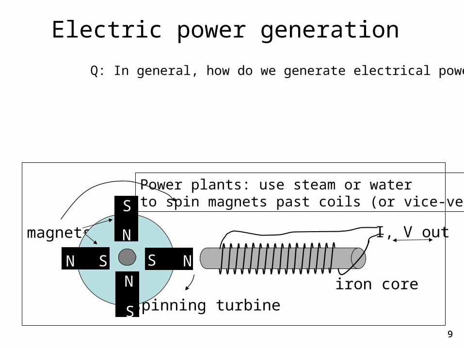
Electric power generation
Q: In general, how do we generate electrical power
9
Power plants: use steam or waterto spin magnets past coils (or vice-versa)
I, V out
iron corespinning turbine
magnets
NN
N
NS
S
S
S

Different types of power plants
• All power plants create electricity by moving a coil of wire relative to a magnetic field (spinning one or the other)
• Use different energy sources to spin the turbine – hydroelectric, nuclear, coal, gas, wind, waves. This is the energy that is converted into electrical energy.
• Some sources more environmentally friendly than others
s
N
s
N
s
N
s N
s
N
s
N
s
N
s
Ntime
B
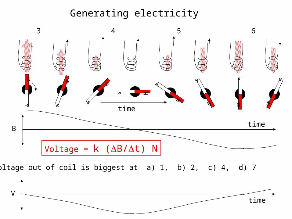
Q: Voltage out of coil is biggest at a) 1, b) 2, c) 4, d) 7
1 2 3 4 5 6 7 8
V
Voltage = k (B/t) N
time
time
Generating electricity
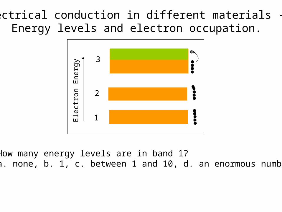
Electrical conduction in different materials - Energy levels and electron occupation.
1
2
3
How many energy levels are in band 1?a. none, b. 1, c. between 1 and 10, d. an enormous number
Ele
ctro
n E
nerg
y

Electrical conduction in materials - Energy levels and electron occupation.
1
2
3
Ele
ctro
n E
nerg
y
True / False1. the upper electrons in band 3 can easily move because there are very close energy levels they can move into.
2. the upper electrons in band 2 can easily move because there are very close energy levels they can move into.
a) 1T 2T, b) 1F 2F, c) 1T 2F, d) 1F 2T

empty
full
What type of material is it?
Fill in the blank: This material is a ______________. When hooked to a battery, electrons in Band 1 will ______________. When hooked to a battery, electrons in Band 2 will ______________. a. conductor, move, moveb. semi-conductor in the dark, not move, move. c. semi-conductor in the light, move, move. d. semi-conductor in the light, not move, move.e. insulator, not move, not move.
Band 1
Band 2
15
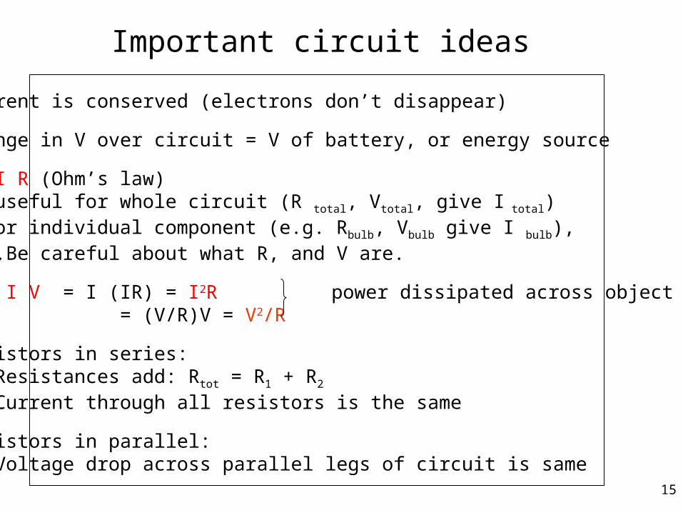
Important circuit ideas
1. Current is conserved (electrons don’t disappear)
2. Change in V over circuit = V of battery, or energy source
3. V= I R (Ohm’s law) - useful for whole circuit (R total, Vtotal, give I total) - or individual component (e.g. Rbulb, Vbulb give I bulb), …….Be careful about what R, and V are.
4. P = I V = I (IR) = I2R power dissipated across object R = (V/R)V = V2/R
5. Resistors in series: Resistances add: Rtot = R1 + R2
Current through all resistors is the same
6. Resistors in parallel:Voltage drop across parallel legs of circuit is same

Series Circuits
1
2120V 200ohm
100ohm
What is the voltage drop across bulb 2?
a. 120V, b. 0V c. 60V, d. 80V, e. 40V
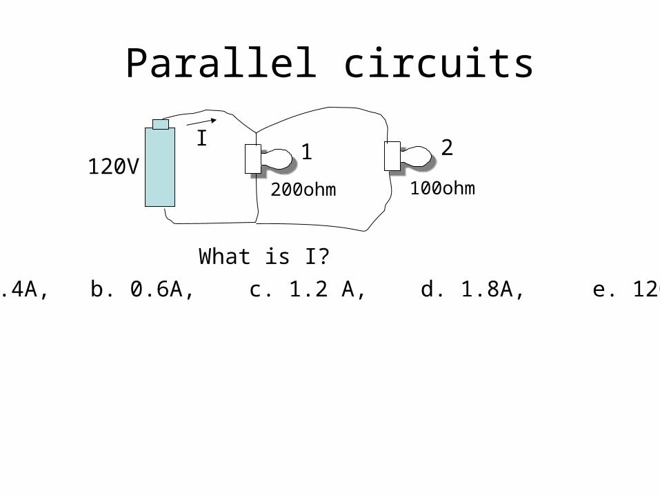
Parallel circuits
1 2120V
200ohm 100ohm
I
What is I?
a. 0.4A, b. 0.6A, c. 1.2 A, d. 1.8A, e. 120A
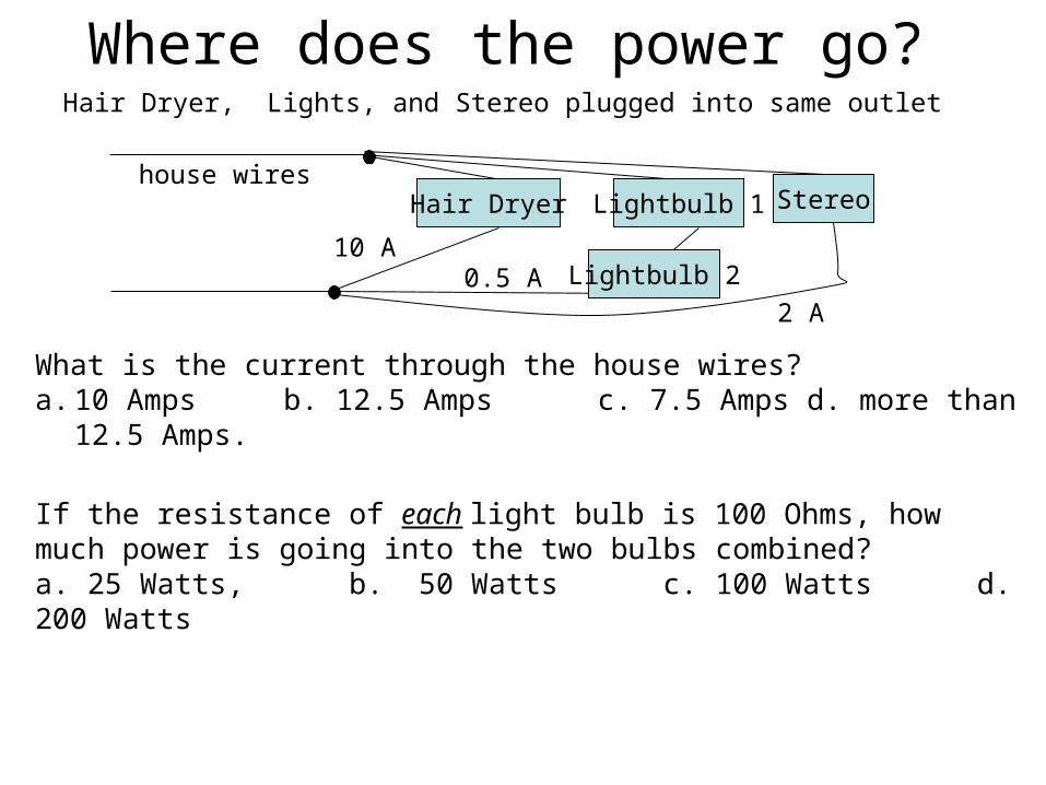
Where does the power go?
Hair Dryer Lightbulb 1 Stereo
Lightbulb 210 A
0.5 A
house wires
2 A
What is the current through the house wires? a. 10 Amps b. 12.5 Amps c. 7.5 Amps d. more than 12.5 Amps.
Hair Dryer, Lights, and Stereo plugged into same outlet
If the resistance of each light bulb is 100 Ohms, how much power is going into the two bulbs combined? a. 25 Watts, b. 50 Watts c. 100 Watts d. 200 Watts

120 V
Why does the light dim when the heater turns on?
Parallel circuits and power loss
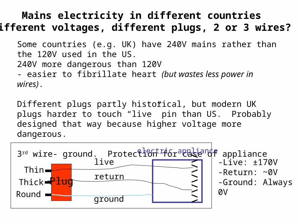
Mains electricity in different countriesDifferent voltages, different plugs, 2 or 3 wires?
Some countries (e.g. UK) have 240V mains rather than the 120V used in the US.240V more dangerous than 120V- easier to fibrillate heart (but wastes less power in wires).
Different plugs partly historical, but modern UK plugs harder to touch “live” pin than US. Probably designed that way because higher voltage more dangerous.
3rd wire- ground. Protection for case of appliance
electric appliance
\/\/\/\/\/
Plug
live
return
ground
Thin
Thick
Round
-Live: ±170V-Return: ~0V-Ground: Always 0V