Embed Size (px)
Citation preview

1
Hearing How Preformed Particle Gels Can Control Water Production
in Mature Oilfields
Missouri University of Science and Technology
(Formerly University of Missouri—Rolla)
August 26, 2015
Presentation at the Mature Fields
North America 2015 Summit

Outline
• What is Preformed Particle Gel (PPG)
• Importance of Gel Treatment for Water Production Control
• A Few Questions Often Being Asked for PPG Treatment
• Case Studies of Field Applications
• Lessons Learned from More Than 5,000 PPG Treatments
• Summary
• Acknowledgement
2

(a) Before swelling (b) After swelling
• Cross-linked polyacrylamide powder, Super Absorbent Polymer
• Size ranging from nano-meter to millimeter
What is Preformed Particle Gel (PPG)
3

Importance of Gel Treatment for Water
Production Control in Mature Oilfields
• Excess water production is the most serious problem to
reduce oil production as oilfields are maturing.
• The total cost to separate, treat, and dispose of water is
approximately $50 billion per year.
• Gel treatments are often one best choice to mitigate
channeling through fractures and super-K streaks.
• Gel treatment is one of cost-effective methods to improve
sweep efficiency.
4

Gel Treatments to Block/Reduce Water Flow through High Permeability Zone/Streak
• Near Wellbore Problems
– High-permeability matrix-rock strata without crossflow
• Far-wellbore Reservoir Problems
5
(c) Fracture
channeling
(a) Vertical heterogeneity
with crossflow (b) High permeability
streaks
(d) Solution
channels
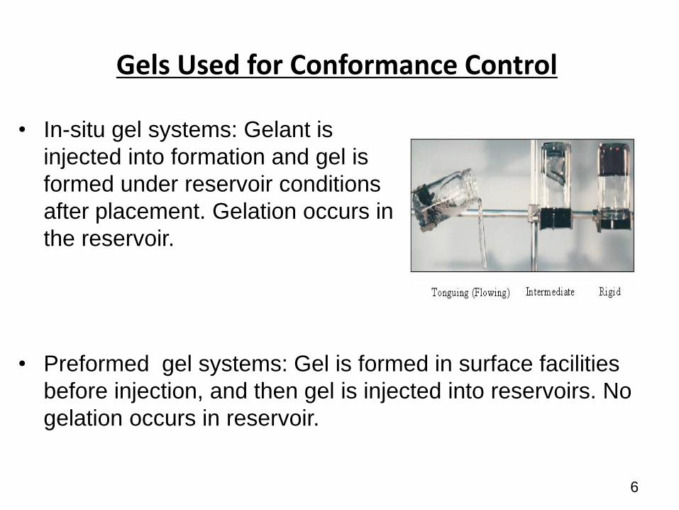
Gels Used for Conformance Control
• In-situ gel systems: Gelant is
injected into formation and gel is
formed under reservoir conditions
after placement. Gelation occurs in
the reservoir.
6
• Preformed gel systems: Gel is formed in surface facilities
before injection, and then gel is injected into reservoirs. No
gelation occurs in reservoir.

Current Preformed Particle Gel Systems
Name Developer Particle Size Applications
Bright
Water®
Chevron, BP and
Nalco (Tirco)
Sub-Micro
(< 1 µm)
60+
injectors
Microgel IFP Micro
(1-10 µm)
10+
producers
PPG PetroChina
MS&T
Halliburton
Millimeter
(10 µm to
millimeters)
5,000+
Injectors in
China
pH Sensitive
polymer
UT Micro Not reported
7

A Few Questions Often Being Asked for PPG Treatment
Q1. Why using particle gels for conformance control?
Q2. Why developing millimeter-sized particles at very
beginning?
Q3, Can mm-sized particles propagating through md-level
formation?
Q4. Can particle gels fully block open fractures, voids, and
conduits?
8

Q1. Why Particle Gels For Conformance Control
9
• Inherent disadvantages of In-Situ Gel
Crosslinking reactions and gel quality are strongly affected by
– Shear of pump, wellbore and porous media
– Adsorption and chromatography of chemical
compositions
– Dilution of formation water
• Particle gel is deformable and easier to transport
through porous media than Hard particle.
• Single component and easy operation in oilfields

Q2: Why using mm-sized (>10µm) particle gels?
• Fractures or high-permeability streaks/channels exist extensively in mature water-flooded reservoirs.
• Millimeter-sized PPGs can preferentially enter into fractures or fracture-like channels/conduits while minimizing gel penetration into low-permeability zones/matrixes.
10
KL
Kh
Water Flooding
KL
Kh
• More polymer
enters low-K
zones comparing
to W.F.
• More polymer
needs to be used
Polymer Flooding
In-situ gel treatment
Nano-particles
Mm-size particles
gel treatment

Q3: Can mm-sized propagate mD porous media?
• Millimeter sized particles cannot penetrate into the porous media with a permeability less than 1000 md.
• If particle size and strength are appropriate, no non-permeable cakes can be formed on the surface of rocks.
Core surface after PPG injection
(a)No damage
(b)Cake but can be flushed out.
Large particles cannot
damage conventional
permeable rocks
11

• If the particles are weak, mm-sized PPGs would form
a cake rather than penetrating into the cores.
(1) Crossflow reduce the negative effect
(2) Acid soak near wellbore to remove cake (SPE172352)
Q3. Can mm-sized propagate mD porous media?
12

A Reservoir with Fracture(s) or Super-K Channels
13

A Reservoir without fractures or Super-K Channels
14
Trial and Error Technique

Q4: Can particle gels fully block
open fractures, voids, and conduits?
• Particle moved piston-like in open fractures and formed
permeable Gelpack.
• The permeability of Gelpack can be a few hundreds to a
few thousands of md, depending on gel strength, particle
size and flow rates.
15

Particles moved piston-like and formed GelPack
Gel movement during PPG injection
(t = 0.2 PV)
(t = 1.5 PV)
(t = 3.2 PV)
(t = 2.5 PV)
Gel Particles is a fracturing-filling material. Particles will form a
particle pack in open fracture/fracture-like features. 16

Brine Created Channels and Flowed in GelPack
(t = 0 PV)
(t = 2.5 PV)
Brine movement during brine injection into Permeable GelPack
in the fracture
(t = 0.8 PV)
(t = 1.5 PV)
PPG cannot fully block open fractures but forms permeable GelPack of
which permeability can be controlled by particle strength and sizes
17

Field Applications
More than 5,000 applications in China and other
countries.
PPG treatment has been successfully applied in:
• Water flooding mature reservoirs without natural
fractures or intentionally hydraulic fractures
• Fracture reservoirs
• High temperature (up to 130°C) high salinity (30%)
reservoirs
• CO2 Flooding Reservoirs
• Polymer Flooding wells
• ASP Flooding wells
PPG weight: 6,600 ~88,000 lbs/well, commonly 17,600-
33,000 lbs per well18

Case 1: First Pilot in Daqing, PetroChina
• Well No and Location: X7-2-F24
• Formation brine salinity: 4,500 mg/L
• Temperature: 40 ºC
• Reservoir type: Sandstone without
natural fractures or intended
hydraulic fractures
• Permeability: Recorded maximum
permeability is 1, 200 md.
19

Case 1: First Pilot in Daqing, PetroChina
• Reservoir Heterogeneity
– Vertical Heterogeneity (Injection profile): only 1/5 perforated zone absorbed water
20

Case 1: First Pilot in Daqing, PetroChina
• Treatment Design
– PPG amounts: 34,100 lbs
– PPG suspension: 3,000 m3 PPG suspension using produced water
– PPG Properties:
• Size: 1.5 mm, 3 mm, and 5 mm
• Swelling ratio: 60~80 times
• Stability: no dehydration within 2 years
– Injection method: PPG Suspension alternated with produced water
21
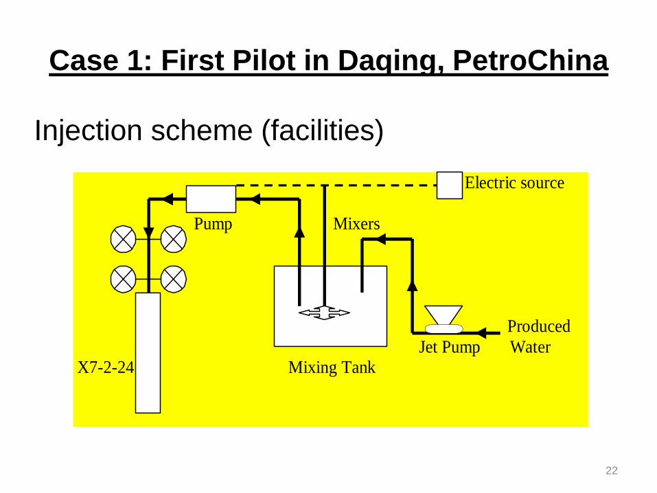
Case 1: First Pilot in Daqing, PetroChina
Electric source
Pump Mixers
Produced
Jet Pump Water
X7-2-24 Mixing Tank
Injection scheme (facilities)
22

Injection performance– multiple stages
Conc
(%)
Size
( mm)
Vol
(m3)
1st 1.0 5 100
2nd 0.5 1.5 600
3rd 0.5 3 1700
4th 0.5 5 6000
2
4
6
8
10
12
14
0 500 1000 1500 2000 2500 3000 3500
Inje
ctio
n P
res
su
re(
MP
a)
PG suspension Volume(m3)
2nd. 3rd 4th
1st
Case 1: First Pilot in Daqing, PetroChina
23Water alternated PPG injection

Case 1: Results from First Pilot in Daqing
• Water injection pressure: increased from 5.0 to 8.2 MPa.
• Oil production: 17,500 bbl of increased Oil within 7 months.
• Injection profile: Water absorption zone thickness from 11.5 m
to 21.5 m.
Before Treatment After Treatment
24
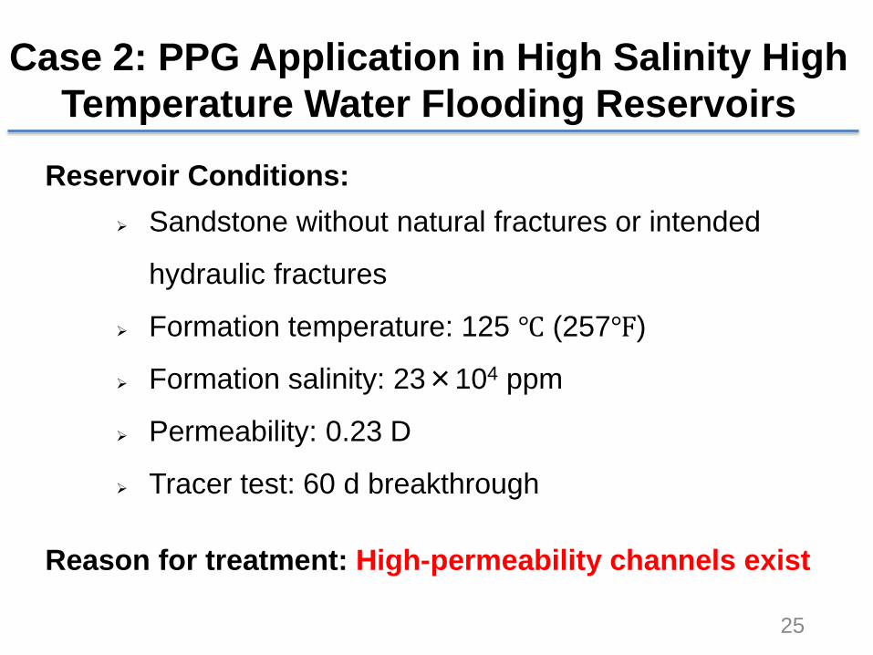
Case 2: PPG Application in High Salinity High
Temperature Water Flooding Reservoirs
Reservoir Conditions:
Sandstone without natural fractures or intended
hydraulic fractures
Formation temperature: 125 ℃ (257℉)
Formation salinity: 23×104 ppm
Permeability: 0.23 D
Tracer test: 60 d breakthrough
Reason for treatment: High-permeability channels exist
25

Case 2: PPG Application in HSHT Reservoirs
Treatment:
• Treated wells: 4 injection wells
• PPG amounts: 375,782 lbs (93,946 lbs/well)
• PPG suspension: 69,260 m3 (17,315 m3/well)
PPG properties:
• Size: 28 μm~1 mm
• Swelling ratio: 15~25 times
• Stability: no dehydration within one year
• High temperature (284 ℉) and salinity resistance (23%)
Slide 26
26

Case 2: PPG Application in HSHT Reservoirs
Slide 27
Injection Pressure Monitoring Results
PPG injection Curve for Well 4
0
435870
1305
17402175
261030453480
Inje
cti
on
Pre
ss
ure
(p
si)
2nd slug
microgel≤28μm24.345t
0
314.5
629
943.5
1258
1572.5
1887
Inje
cti
on
Ra
te
(b
bl/
d)
0
1000
2000
3000
2012.12.2 12/17 2013.1.1 1/16 1/31 2/15 3/2 3/17 4/1 4/16 5/1 5/16
Co
nc
en
tra
tio
n
(p
pm)
4th slug
PPG0.1-0.25mm13.912t
3rd slug
PPG≤0.1mm10.432t
5th slug
PPG0.25-0.5mm12.519t
1st slug
microgel≤28μm2.782t
6th slug
PPG+Gel0.25-0.5mm8.346t
27

Case 2: PPG Application in HSHT Reservoirs
Slide 28
Drawdown Test for Injection Well 4
Pressure drawdown test for Well 4
0
500
1000
1500
2000
2500
3000
3500
0 15 30 45 60 75 90
Pre
ss
ure
(p
si)
Time (90 min)
2nd slug
3rd slug
4th slug
5th slug
after treatment
before treatment
28

Case 2: PPG Application in HSHT Reservoirs
Slide 29
Increased Oil 204,188 bbl
Oil incr. per
PPG 170.5 t/t
Decline Curve for 9 Production Wells
Before Treatment After Treatment
0
20
40
60
80
100
120
140
160
180
0 12 24 36
Pro
du
cti
on
Ra
te (
t/d
)
Time(month)
27,971 t
29

Case 3: PPG Application in Polymer Flooding
Reservoir Conditions:
Sandstone with natural fracture
Temperature: 33oC (91.4℉)
Salinity: 5600~5700 ppm
Permeability: 0.16 D
Reason for treatment:
Polymer early breakthrough
Slide 30
30

PPG Application in Polymer Flooding
Slide 31
0
100
200
300
400
500
600
700
800
20101026 20110114 20110517 20110720 20111010 20111222 20120409 20120629 20120918 20130109
Po
lym
er
Co
ncen
trati
on
(p
pm)
Time(d)
After treatmentBefore treatment
Polymer concentration for 18 production wells
Treatment
31

Lessons Learned
from Field Application Results
• Fracture or fracture-like channels widely exists in
mature oilfields but it has not been recognized by
those engineers without field experience.
• No injectivity problem was found for most treatments
even though these reservoirs have no natural fractures
or intentionally hydraulic fractures.
• “Trial and Error” technique can be used for better gel
treatment results
• Negative effect was rarely found.
• PPG treatment is a simple and cost-effective method to
control water production.32

Summary
• PPGs have been successfully synthesized in commercial scale
and applied in mature oilfields to control water production
• PPG strength and size are controllable. It can overcome some
distinct drawbacks inherent to in-situ gelation systems.
• Swollen PPG forms a gel-pack after placement in a fracture,
and the gel-pack permeability can be controlled by particle size
and strength.
• Millimeter-sized (10 µm-mm) PPGs have been successfully
applied in more than 5000 wells without injectivity problems
• Trial and Error method can be used for mm-sized PPG
treatments.
• PPG treatment is a simple and cost-effective method to control
conformance for water and polymer flooding. 33

Acknowledgements
34

Selected Journal Publications for Particle Gels
1. Imqam, A.**; Elue,H.; Bai,B*., Hydrochloric Acid Applications to Improve Preformed Particle Gel Conformance Control Treatment, SPE Production. (in revision)
2. Imqam, A.; Bai,B., (2015), Optimize the Strength and Size of Preformed Particle Gels for Better Conformance Control Treatment, Fuel 148, 178-185, 2015.
3. Goudarzi, A.; Zhang, H.**; Varavei, A.; Taksaudom, P.; Hu Y.**; Delshad, M.; Bai, B.; Sepehrnoori, K.; “A Laboratory and Simulation Study of Preformed Particle Gels for Water Conformance Control,” Fuel, 140, 502-513.
4. Imqam, A.**; Bai, B*.; Preformed Particle Gel Extrusion through Open Conduits during Conformance Control Treatments, SPE Journal, 2014
5. Muhammed, F.A.**; Bai, B.*; Tang, T.**, (2012) Experimental Study of the Interaction between Surfactants and Super Absorbent Polymer Gel, Journal of Petroleum Sciences and Engineering 90: 159-164.
6. Elsharafi, M**, Bai, B*. (2012) Effect of Weak Preformed Particle Gel on Unswept Oil Zones/Areas during Conformance Control Treatments, Ind. Eng. Chem. Res.51 (35), 11547–11554.
7. Zhang, H.**; Bai, B*. (2011) “Preformed Particle Gel Transport through Open Fractures and its Effect on Water Flow,” SPE Journal 16(2), 388-400.
8. Wu, Y.**, Tang, T**., Bai, B.* (2011) “An experimental study of interaction between surfactant and particle hydrogels”, Polymer 52, 452-460.
9. **Zhang, H., Challa, R., and Bai, B*. (2010), “Using Screening Test Results to Predict the Effective Viscosity of Swollen Superabsorbent Polymer Particles Extrusion through an Open Fracture” Industrial & Engineering Chemistry 49, 12284-12293.
10. Bai, B.*, Li, L., Liu, Y., Li, Y., (2007) “Conformance Control by Preformed Particle Gel: Factors Affecting its Properties and Applications,” SPE Reservoir Evaluation and Engineering 10 (4), 415-421. DOI: 10.2118/89389-PA
11. Bai, B.*, Liu, Y., Coste, J-P., (2007) “Preformed Particle Gel for Conformance Control: Transport Mechanism through Porous Media,” SPE Reservoir Evaluation and Engineering, 10 (2), 176-184. DOI: 10.2118/89468-PA
35
Thanks!
Questions?
36

PPG
Dispersion
preparation
Screw pumpWater-injection station
Facilities to Pump PPG
• Large amount of
PPG injection for
multiple wells
• The second largest chemical EOR technology after polymer flooding in China
• Field-wide application rather than single well treatment 37

Facilities to Pump PPG
Picture of PPG Injection Site
38

Facilities to Pump PPG
Picture of PPG Injection Site
39

0.05% Brine 0.25% Brine 1% Brine 10 % Brine
Fully Swollen Partially Swollen
Dry particle (stiff particle)
The more swelling, the more deformable
Q4: Do we need control swelling rate if we
only consider injectivity?
40

Experiment Descriptions
PPG size (dry): ~ 0.6 mm
Tubes ID : 10.922, 3.048,1.752, and 0.774 mm
Brine Concentrations: 0.05, 0.25, 1, and 10%
0
50
100
150
200
0.05 0.25 1 10Brine concentrations, %
Swelling Ratio
0
200
400
600
800
1000
1200
1400
0.05 0.25 1 10
Brine concentrations, %
Gel strength, pa
41

Conduit Experiment: Methodology and Experiment

1
10
100
1000
0 500 1000 1500 2000 2500
Ge
l in
jec
tio
n p
res
su
re (
ps
i)
Gel injection velocity (ft/day)
0.05% 0.25% 1% 10%
Conduit opening size 3.048 mm
PPG Injection Pressure
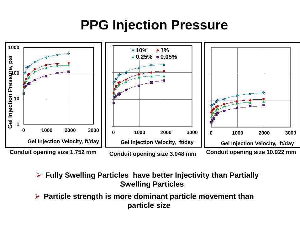
Conduit opening size 1.752 mm
Fully Swelling Particles have better Injectivity than Partially
Swelling Particles
Particle strength is more dominant particle movement than
particle size
1
10
100
1000
0 1000 2000 3000
Ge
l In
jec
tio
n P
res
su
re, p
si
Gel Injection Velocity, ft/day
0 1000 2000 3000
Gel Injection Velocity, ft/day
10% 1%0.25% 0.05%
0 1000 2000 3000
Gel Injection Velocity, ft/day
Conduit opening size 10.922 mmConduit opening size 3.048 mm
PPG Injection Pressure

1
10
100
1000
10000
100000
1000000
1 100 10000
Resid
ual
Resis
tan
ce F
acto
r
Brine Injection Velocity, ft/day
1 100 10000
Brine Injection Velocity, ft/day
0.05% 10%
1 100 10000
Brine Injection Velocity, ft/day
Conduit opening size 1.75 mm Conduit opening size 3.048 mm Conduit opening size 10.92 mm
PPG Resistance to Water Flow
45

A Swollen Particle Transport through a Throat
a. PPG moving to throat b. Losing water from PPG front
c. Elongated particle filling throat d. Particle through throat
particle
glass

A Process of a Particle through Throat(s)
a. PG was moving to throat. b. PG was broken into two particles c. Bigger part tried to pass
through throat
d. PG become more arched e. Two ends of PG enter two
throats
f. PG was broken again and
passed through throat
glass
Throat
PPG

Transport Mechanism of a Particle through a Throat Smaller its Size
1
2
3
Dehydrated
Broken
Deformed & enlongation