Embed Size (px)
Citation preview
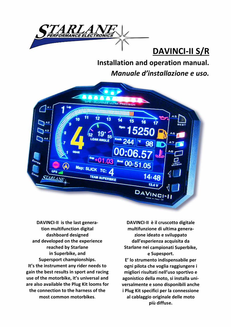
DAVINCI-II S/R Installation and operation manual.
Manuale d’installazione e uso.
DAVINCI-II is the last genera-tion multifunction digital
dashboard designed and developed on the experience
reached by Starlane in Superbike, and
Supersport championships. It’s the instrument any rider needs to
gain the best results in sport and racing use of the motorbike, it’s universal and are also available the Plug Kit looms for
the connection to the harness of the
most common motorbikes.
DAVINCI-II è il cruscotto digitale multifunzione di ultima genera-
zione ideato e sviluppato dall’esperienza acquisita da
Starlane nei campionati Superbike,
e Supesport. E’ lo strumento indispensabile per ogni pilota che voglia raggiungere i migliori risultati nell’uso sportivo e
agonistico della moto, si installa uni-versalmente e sono disponibili anche i Plug Kit specifici per la connessione
al cablaggio originale delle moto più diffuse.

1
2
MAAT
software
For the Data Analysis
you can download the
MAAT software
from the Technical Support
page on our website
www.starlane.com
http://www.starlane.com/en_downloads.htm
MAAT
software
Per l’analisi dei dati è
possibile scaricare il
software MAAT
direttamente dalla pagina di
Supporto Tecnico del sito
www.starlane.com
http://www.starlane.com/downloads.htm
3
Contents
Introduction ................................................................ 6
Functions ............................................................................ 6
Front Panel ......................................................................... 6
Installation of DAVINCI-II ............................................. 7
Assembly............................................................................. 7
Position and Orientation ............................................. 8
Connecting the dedicated Plug Kit ............................... 9
Connecting the universal loom .................................. 10
Connecting warning lights ................................................ 11
Connection of the Speed signal input wire for gear indication and odometer ............................................. 12
Or mounting the Speed Kit (Optional for bikes with mechanical speed transmission) .................................. 12
Main Screen ...................................................................... 16
Multi-page menu .............................................................. 16
GPS signal acquisition ....................................................... 17
Configuration .................................................................... 17
Selecting the language ................................................. 17
Aligning the GPS clock to the local time zone ............. 17
Setting the lap time Freeze Time ................................ 17
Selection of the units of measurement ....................... 18
Setting the RPM reading parameters .......................... 18
Setting the LED Bar ........................................................... 18
Setting the RPM Bar on LCD ............................................. 19
Gear programming ........................................................... 20
Setting up the number of gears of the vehicle............ 20
Gear learning ............................................................... 21
Setting the speed reading parameters ........................ 21
Setting the Warning Lights ........................................... 23
Setting the Cooler Temperature reading ..................... 25
How to set the lap triggers on Starlane devices .......... 26
STARLANE Track library ................................................ 26
SAFD-2 automatic positioning function ............................ 27
Track management ........................................................... 28
Learning the Finish Line and Intermediate positions ... 28
Storing the coordinates of the Finish Line and Intermediate positions ........................................................................... 30
Choose one of the free positions between 01 e 16. ..... 30
Loading the track coordinates ..................................... 30
Clearing the personal track list .................................... 30
Contenuti
Introduzione ............................................................... 6
Funzioni.............................................................................. 6
Pannello Frontale ............................................................... 6
Installazione di DAVINCI-II ........................................... 7
Montaggio.......................................................................... 7
Posizione e Orientamento ........................................... 8
Connessione del Plug Kit dedicato ............................... 9
Connessione del cablaggio universale ........................ 10
Connessione dei segnali per le spie ................................. 11
Connessione cavo lettura segnale Velocità per indicazione marcia e distanza percorsa ......................................... 12
O montaggio dello Speed Kit (Opzionale per moto non dotate di segnale velocità elettronico) ....................... 12
Schermata principale ....................................................... 16
Menu multipagina ........................................................... 16
Acquisizione del segnale GPS ........................................... 17
Configurazione ................................................................. 17
Selezione della lingua .................................................. 17
Allineamento dell’orologio GPS con il fuso orario ...... 17
Impostazione del tempo di visualizzazione a fine giro 17
Selezione delle unità di misura ................................... 18
Impostazione dei parametri di lettura regime motore 18
Impostazione della Barra LED .......................................... 18
Impostazione della Barra RPM sul display ....................... 19
Programmazione delle marce .......................................... 20
Impostazione del numero di marce del veicolo ......... 20
Apprendimento dei rapporti ....................................... 21
Impostazione dei parametri di lettura della velocità .. 21
Impostazione delle Spie .............................................. 23
Impostazione della lettura di Temperatura Liquido Refrigerante ................................................................ 25
Come impostare i traguardi sui dispositivi Starlane .... 26
Libreria circuiti STARLANE ........................................... 26
Funzione di posizionamento automatico SAFD-2 ............ 27
Gestione circuiti ............................................................... 28
Apprendimento della linea di traguardo e degli intermedi .................................................................................... 28
Memorizzazione delle coordinate di Traguardo e Intermedi ......................................................................................... 30
Scegliere una delle posizioni libere tra 01 e 16. ........... 30
Richiamare le coordinate di un circuito ...................... 30
4
Resetting the active track ............................................ 30
Automatic track recognition ........................................ 30
Analysis of the stored times ......................................... 31
Managing the Hour Meters .............................................. 33
Menu: MEMORY > SHOW HOUR METERS ....................... 33
Memory Management ..................................................... 33
Session recording ......................................................... 33
Manual recording......................................................... 34
Checking the memory in use ....................................... 34
Memory clearing .......................................................... 34
Memory Formatting..................................................... 34
Computer connections ..................................................... 35
USB cable connection .................................................. 36
Configuring the Bluetooth connection ........................ 36
Updating the DAVINCI-II firmware ................................... 36
Checking the Firmware version installed ..................... 37
Downloading the update ............................................. 37
Device name ..................................................................... 37
Loading tracks ................................................................... 37
Track export ...................................................................... 38
Open Circuit and Performance Test Functionality39
Mode selection ............................................................ 39
Learn the finish lines and intermediates in the OPEN LAUNCHED mode ......................................................... 40
Learn the finish lines and intermediates in the OPEN STILL mode................................................................................. 42
Accelerometer sensitivity set-up ................................. 44
Acceleration test in the Performance Test mode ............. 45
Carry out the Acceleration Test ................................... 45
Activation from remote button ........................................ 46
Analysis of acquired data .................................................. 46
Calibrating TPS signal, managing WID wireless modules on DAVINCI-II S and Advanced functions on DAVINCI-II R ................................................................................. 48
Acquisition channels managed by DAVINCI-II ................. 49
Channels acquired by DaVinci-II S ................................ 49
Channels acquired by DaVinci-II R: .............................. 49
Canali acquisiti da DaVinci-II R: .................................... 49
Distinction between Analog and Digital channels ....... 52
Channel setup ................................................................... 52
Define an Analog Channel ............................................ 52
Quick channel monitoring................................................. 54
Cancellare la lista circuiti personale ............................ 30
Annullare il circuito attivo ........................................... 30
Riconoscimento automatico del circuito .................... 30
Analisi dei tempi memorizzati ..................................... 31
Gestione dei Contaore ..................................................... 33
Gestione della memoria................................................... 33
Registrazione delle sessioni......................................... 33
Registrazione manuale ................................................ 34
Verifica della memoria utilizzata ................................. 34
Cancellazione della memoria ...................................... 34
Formattazione della Memoria .................................... 34
Collegamenti con il computer .......................................... 35
Connessione con cavo USB ......................................... 36
Impostazione della connessione Bluetooth ................ 36
Aggiornamento del firmware di DAVINCI-II ..................... 36
Verifica della versione di Firmware installata ............ 37
Scarico dell’aggiornamento......................................... 37
Nome del dispositivo ....................................................... 37
Caricamento dei circuiti ................................................... 37
Esportazione dei circuiti ................................................... 38
Funzionalità di Circuito Aperto e Performance Test ................................................................................. 39
Selezione della modalità ............................................. 39
Apprendimento dei traguardi e degli intermedi nella modalità CIRCUITO APERTO LANCIATO ........................... 40
Apprendimento dei traguardi e degli intermedi nella modalità CIRCUITO APERTO DA FERMO .......................... 42
Impostazione della sensibilità dell'accelerometro ...... 44
Test di accelerazione con la modalità Test di Prestazione 45
Esecuzione del Test di Accelerazione .......................... 45
Attivazione da pulsante remoto ...................................... 46
Analisi dei dati acquisiti ................................................... 46
Calibrazione segnale TPS, gestione moduli wireless WID su DAVINCI-II S e Funzioni avanzate di DAVINCI-II R ... 48
Canali acquisizione gestiti da DAVINCI-II ........................ 49
Canali acquisiti da DaVinci-II S:.................................... 49
Distinzione tra canali Analogici e Digitali .................... 52
Impostazione canali ......................................................... 52
Definire un Canale Analogico ...................................... 52
Verifica rapida dei canali .................................................. 54
Monitor canali analogici .................................................. 54
Monitor canali digitali ...................................................... 54
5
Analog channels monitor .................................................. 54
Digital channels monitor................................................... 54
Channel monitoring on optional CAN BUS modules ........ 54
Channel monitoring on ECU data line .............................. 54
Calibration of analog sensors ........................................... 55
Calibration of the throttle position sensor (TPS) ......... 56
Calibration of linear potentiometers (e.g. Suspension Sensors)........................................................................ 57
Cleaning the surfaces........................................................ 59
Notes ................................................................................ 59
Important for 2 Stroke Vehicle users.......................... 59
Warranty........................................................................... 60
Monitor dei canali sui moduli CAN BUS opzionali ........... 54
Monitor canali della linea dati della ECU ......................... 54
Calibrazione dei sensori analogici .................................... 55
Calibrazione del sensore di apertura acceleratore (TPS)56
Calibrazione dei potenziometri lineari (es. Sensori Sospensione) ............................................................... 57
Pulizia delle superfici ....................................................... 59
Note ................................................................................. 59
Importante per utenti di Veicoli 2 Tempi ................... 59
Garanzia ........................................................................... 60
6
Introduction
Functions
DAVINCI-II carries out the following basic functions:
Dashboard with digital and analog screens.
GPS Lap timer with trajectories data acquisition.
Full data acquisition system in version DaVinci-II R.
Both S and R versions can be expanded with optional WID wireless modules.
Introduzione
Funzioni
DAVINCI-II svolge le seguenti funzioni base:
Cruscotto con schermate digitali ed analogiche.
Cronometro GPS con acquisizione traiettorie.
Sistema acquisizione dati completo in versione DaVinci-II R.
Entrambe le versioni S e R sono espandibili con moduli wireless WID opzionali.
Front Panel
Engine RPM Bar
SHIFT LIGHT
Settable ALARM LEDS
BEST LAP LED
COLOR TFT DISPLAY
BUTTONS
LIGHT SENSOR for automatic dimmer
Pannello Frontale
Il pannello frontale di DaVinci-II presenta:
Barra lettura RPM
FLASH DI FUORIGIRI
LED ALLARMI impostabili
LED BEST LAP
DISPLAY TFT a COLORI
PULSANTI
SENSORE LUMINOSITA’ esterna per autoregolazione luminosità
The “Best Lap” LED is a very useful function to immediately give immediate information on a better performance without distract-ing the driver by making him read the dis-play.
If the “BEST LAP” LED lights on it means a better time compared to the previous lap.
If the “BEST LAP” LED blinks it means you have just closed your best lap time of the session in progress.
Il LED “Best Lap” è una funzione molto utile per dare informazioni immediate sul miglio-ramento della prestazione senza distrarre il pilota per la lettura del display.
Il LED “BEST LAP” si illumina fisso se viene migliorato il tempo rispetto al giro precedente.
Il LED “BEST LAP” lampeggia se il giro appena concluso è il migliore della sessione in corso.
Il LED “BEST LAP” funziona anche al
7
The “BEST LAP” LED also works for the intermediates if they have been set.
passaggio sugli Intermedi se questi sono stati impostati.
Installation of DAVINCI-II
Assembly
DAVINCI-II is easily installed in the wind-shield of a Motorbike, on the fork plate, on the steering wheel of a Go Kart, or on the dashboard of a Car.
Installazione di DAVINCI-II
Montaggio
DAVINCI-II DaVinci si installa sul telaietto originale della moto con i supporti elastici forniti. Se avete acquistato il Plug Kit specifi-co seguite le istruzioni in esso contenute.
IMPORTANT!
READ CAREFULLY THE FOLLOWING INDICATIONS BEFORE PROCEEDING WITH
THE INSTALLATION
As any other electronic, or just electric de-vice (see dashboards, relays or fuses), al-ways comes mounted on rubber to void the inexorable damages caused by vibra-tions; also the present apparatus must be installed following carefully such precau-tion.
IMPORTANTE!
LEGGERE ATTENTAMENTE LE PRESENTI INDICAZIONI PRIMA DI PROCEDERE CON
L’INSTALLAZIONE
Come ogni dispositivo elettronico, o anche solo elettrico (vedi cruscotti, relay o fusibili), viene sempre montato su gomma per evita-re gli inesorabili danni causati dalle vibra-zioni; anche il presente apparato deve esse-re installato seguendo accuratamente tale precauzione.
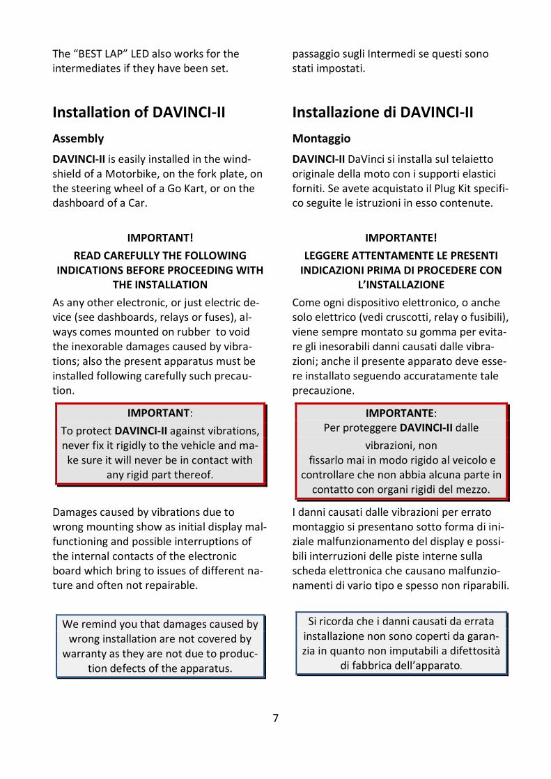
IMPORTANT:
To protect DAVINCI-II against vibrations, never fix it rigidly to the vehicle and ma-ke sure it will never be in contact with
any rigid part thereof.
IMPORTANTE: Per proteggere DAVINCI-II dalle
vibrazioni, non fissarlo mai in modo rigido al veicolo e
controllare che non abbia alcuna parte in contatto con organi rigidi del mezzo.
Damages caused by vibrations due to wrong mounting show as initial display mal-functioning and possible interruptions of the internal contacts of the electronic board which bring to issues of different na-ture and often not repairable.
We remind you that damages caused by wrong installation are not covered by
warranty as they are not due to produc-tion defects of the apparatus.
I danni causati dalle vibrazioni per errato montaggio si presentano sotto forma di ini-ziale malfunzionamento del display e possi-bili interruzioni delle piste interne sulla scheda elettronica che causano malfunzio-namenti di vario tipo e spesso non riparabili.
Si ricorda che i danni causati da errata installazione non sono coperti da garan-zia in quanto non imputabili a difettosità
di fabbrica dell’apparato.
8
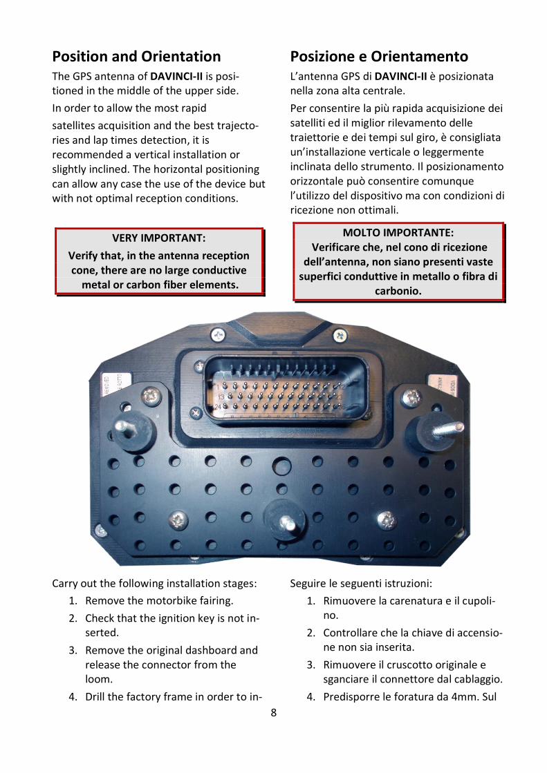
Position and Orientation The GPS antenna of DAVINCI-II is posi-tioned in the middle of the upper side.
In order to allow the most rapid
satellites acquisition and the best trajecto-ries and lap times detection, it is recommended a vertical installation or slightly inclined. The horizontal positioning can allow any case the use of the device but with not optimal reception conditions.
VERY IMPORTANT:
Verify that, in the antenna reception cone, there are no large conductive
metal or carbon fiber elements.
Posizione e Orientamento L’antenna GPS di DAVINCI-II è posizionata nella zona alta centrale.
Per consentire la più rapida acquisizione dei satelliti ed il miglior rilevamento delle traiettorie e dei tempi sul giro, è consigliata un’installazione verticale o leggermente inclinata dello strumento. Il posizionamento orizzontale può consentire comunque l’utilizzo del dispositivo ma con condizioni di ricezione non ottimali.
MOLTO IMPORTANTE: Verificare che, nel cono di ricezione
dell’antenna, non siano presenti vaste superfici conduttive in metallo o fibra di
carbonio.
Carry out the following installation stages:
1. Remove the motorbike fairing.
2. Check that the ignition key is not in-serted.
3. Remove the original dashboard and release the connector from the loom.
4. Drill the factory frame in order to in-
Seguire le seguenti istruzioni:
1. Rimuovere la carenatura e il cupoli-no.
2. Controllare che la chiave di accensio-ne non sia inserita.
3. Rimuovere il cruscotto originale e sganciare il connettore dal cablaggio.
4. Predisporre le foratura da 4mm. Sul
9
stall the 3 Silent Blocks with M4-thread supplied using the position of the holes available on the universal bracket provided.
5. Mount the 3 Silent Blocks on the bracket in position corresponding to the 3 holes made on the frame.
6. Fix DaVinci-II onto the bracket using the 4 M3-thread rubber insertions with the specific M3 screws. Atten-tion! Never remove the Silent Block supports between the dashboard and the bike frame.
7. Follow the connection instructions below.
8. Once the connections have been completed insert the ignition key and turn it in the ON position.
DaVinci-II will be switched on.
ATTENTION!
The connectors at the back of DaVinci-II can be the same as those used on some mass-produced motorbikes, anyway never connect the motorbike harness directly with the main connector be-cause internal contacts are different and the connection would definitively damage DaVinci-II and motorbike elec-tronics.
Connecting the dedicated Plug Kit
If you purchased DaVinci-II with one of the optional plug-in kits for the various motor-cycle models, simply connect the plug-kit
telaietto originale per i 3 supporti elastici Silent Block con filetto M4 forniti basandosi sulla posizione dei fori disponibili sulla staffa di supporto fornita nella confezione.
5. Fissare sulla staffa i 3 supporti elastici nella posizione opportunamente de-finita.
6. Fissare DaVinci-II alla staffa con i quattro inserti elastici tramite le ap-posite viti M3. Attenzione! Non ri-muovere mai i supporti Silent Block tra il cruscotto e il telaietto.
7. Seguire le istruzioni di connessione del presente manuale.
8. Una volta terminate le connessioni inserire la chiave di accensione e por-tarla in posizione ON.
DaVinci-II si accenderà.
ATTENZIONE!
I connettori sul retro di DaVinci-II pos-sono essere dello stesso modello di quelli usati su alcune moto di serie, in ogni caso i cablaggi della moto non van-no mai collegati direttamente al connet-tore principale in quanto i contatti in-terni sono diversi e il collegamento danneggerebbe irreparabilmente DaVinci-II e l’elettronica della moto.
Connessione del Plug Kit dedicato
Se avete acquistato DaVinci-II con uno dei plug kit opzionali dedicati per i vari modelli di moto, sarà sufficiente collegare il plug kit
10
directly to the original connector on the motorcycle's wiring harness.
DaVinci-II can automatically detect the connected plug-kit model and automatical-ly set the main operating parameters for that model.
In any case it is always possible to manually select the bike model among the prede-fined ones:
OPTIONS > VEHICLE MODEL
Obviously, in case of connection with a dedicated Plug Kit, the operations
indicated in the following paragraph relating to connection of the universal wiring, will not have to be performed.
Connecting the universal loom
In the event that you do not use a plug kit designated for your bike but you are per-forming the installation with the DaVinci-II universal wiring, follow the following con-nection instructions.
DaVinci-II power supply connection
Connect the Red power supply wire to a key-switched +12V and the Black GND wire to the chassis or to any ground point, such as the Negative of the battery.
Engine RPM wire Connection
DaVinci-II fits to different inputs for the en-gine speed reading, respectively connected to the VIOLET wire for
low voltage signals (square wave 0-5V or 0-12V) or to the ORANGE wire for high volt-
direttamente al connettore originale sul cablaggio della moto.
DaVinci-II è in grado di rilevare in automati-co il modello di plug kit collegato e di impo-stare automaticamente i parametri di fun-zionamento principali per quel modello.
In ogni caso è sempre possibile anche sele-zionare manualmente il modello di moto tra quelli predefiniti:
OPZIONI > MODELLO VEICOLO
Ovviamente, in caso di connessione con Plug Kit dedicato, non dovranno essere
eseguite le operazioni riportate nel seguente paragrafo relativo alla
connessione del cablaggio universale.
Connessione del cablaggio universale
Nel caso in cui non si utilizzi un plug kit de-dicato per la propria moto ma si stia effet-tuando l’installazione con il cablaggio uni-versale di DaVinci-II, seguire le seguenti in-dicazioni di connessione.
Connessione dell’ alimentazione di DaVinci-II
Connettere il cavo Rosso di alimentazione ad un +12V sotto chiave e il cavo Nero di massa al telaio o ad un qualsiasi punto di massa, come il Negativo della batteria.
Connessione cavo lettura Regime Motore
DaVinci-II è dotato di due ingressi diversi per effettuare la lettura del regime motore, rispettivamente collegati al filo VIOLA per segnali in bassa tensione (onda quadra 0-5V oppure 0-12V) oppure al filo ARANCIONE
11
age inputs (0-150V) that will never have to be kept connected contemporaneously.
A. Low voltage connection:
Connect the VIOLET wire to the RPM (Tacho) signal output wire that goes from the ECU to the connector of the factory instrument panel.
If you connect this wire the ORANGE wire will not have to be connected.
B. High voltage connection:
Connect the ORANGE wire to the driver wire of one of the inductive ignition coils. If you connect this wire the VIOLET wire will not have to be connected.
ATTENTION! Don’t connect absolutely the VIOLET wire to any of the ignition
coils wires or to other wires with voltage higer then the specified in order to void any damage to the engine speed input
channel.
Connecting warning lights
DaVinci-II is able to control Neutral, Oil Pressure, Fuel Reserve, Beam, Turn warning lights. The determination of warning lights switching signals can’t be standardized be-cause of the different ways of activation used by the makers for each model, so warning lights functioning is not guaran-teed on DaVinci-II Universal version even if the powerful software allows a very wide possibility of configuration for most of the bikes in the current productions.
Neutral = Blue wire
Can be connected to the wire of the specific light on the harness going to the factory dashboard or directly to the wire coming out from the neutral switch inside the
per ingressi in alta tensione (0-150V) che non dovranno mai essere collegati in con-temporanea.
A. Connessione in bassa tensione: Connettere il cavo VIOLA al cavo del segnale RPM (Tacho) che dalla cen-tralina va al connettore del pannello strumenti originale. Se viene collegato questo filo, il filo ARANCIONE non dovrà essere collegato.
B. Connessione in alta tensione: Connettere il filo ARANCIONE al filo di pilotaggio di una delle bobine accensione induttive. Se viene collegato questo filo, il filo VIOLA non dovrà essere collegato.
ATTENZIONE! Non collegare assoluta-mente il filo VIOLA ai fili delle bobine o ad altri fili che possono avere tensioni
superiori a quanto specificato per evitare di danneggiare il canale di lettura giri
motore.
Connessione dei segnali per le spie
DaVinci-II gestisce le spie di Folle, Pressione Olio, Riserva Carburante, Abbaglianti, Frecce e MIL. Non è possibile standardizzare il se-gnale di accensione delle spie a causa dei differenti modi di attivazione usati dalle ca-se produttrici per ogni modello, quindi il funzionamento delle spie di allarme non è garantito sulla versione Universale di DaVinci-II anche se l’avanzato software permette larghe possibilità di configurazio-ne per la maggior parte delle moto attual-mente in produzione.
Folle= filo Blu:
Può essere collegato al filo di accensione della rispettiva spia sul cablaggio che arriva al cruscotto originale oppure direttamente al cavo dell’interruttore del folle in uscita
12
gearbox.
Oil= White wire
Can be connected to the wire of the specific light on the harness going to the factory dashboard or directly to the wire coming out from the oil sensor inside the engine.
Fuel=Yellow wire
Can be connected to the wire of the specific light on the harness going to the factory dashboard or directly to the wire coming out from the fuel sensor on the tank.
Beam=Grey wire
Can be connected to the wire of the specific light on the harness going to the factory dashboard or directly to the wire supplying the power to the beam light.
Turn Lights= Purple wire for Right Turn and Green wire for Left Turn:
Can be connected to the wire of the specific light on the harness going to the factory dashboard or directly to the wire supplying the power to the turn light.
MIL (FI)= Light-Blue wire:
Can be connected to the wire of the specific light on the harness going to the factory dashboard.
Connection of the Speed signal input wire for gear indication and odometer
Or mounting the Speed Kit (Optional for bikes with mechanical speed transmission)
Connect the GREEN wire to the Speed sig-nal output wire that goes from the speed
dalla scatola del cambio.
Pressione Olio=filo Bianco:
Può essere collegato al filo di accensione della rispettiva spia sul cablaggio che arriva al cruscotto originale oppure direttamente al cavo del sensore olio in uscita dalla carter motore.
Carburante=filo Giallo:
Può essere collegato al filo di accensione della rispettiva spia sul cablaggio che arriva al cruscotto originale oppure direttamente al cavo del sensore di riserva in uscita dal serbatoio carburante.
Abbaglianti=filo Grigio:
Può essere collegato al filo di accensione della rispettiva spia sul cablaggio che arriva al cruscotto originale oppure direttamente al cavo di alimentazione del faro abbaglian-te.
Frecce= filo Viola per Freccia Destra e filo Verde per Freccia Sinistra:
Può essere collegato al filo di accensione della rispettiva spia sul cablaggio che arriva al cruscotto originale oppure direttamente al cavo di alimentazione della freccia.
MIL (FI)=filo Azzurro:
Può essere collegato al filo di accensione della rispettiva spia sul cablaggio che arriva al cruscotto originale.
Connessione cavo lettura segnale Velocità per indicazione marcia e distanza percorsa
O montaggio dello Speed Kit (Opzionale per moto non dotate di segnale velocità elettronico)
Connettere il cavo VERDE al cavo di lettura Velocità che va dal sensore velocità (solita-
13
sensor 8usually positioned on one of the wheels or on the gearbox) to the connector of the factory instrument panel. If on your bike there is no speed sensor and the speed value is sent to the speedometer by a mechanical cord you can mount the optional Speed Kit (code CSKNP) which de-tects the bolts of the brake rotor passing in front of the sensitive tip of the sensor. On the basis of the number of impulses and the wheel circumference entered, DaVinci calculates the speed and distance run.
For a correct gear indication the sensor must sense the REAR wheel speed.
Carry out the following installation stages:
1. Insert the sensor into the hole on the support and position it so that the brake disk bolts run at a distance of about 1 mm. from the sensor tip. In most cases you can drill the sup-port of the rear brake caliper and fix the sensor directly without the sup-plied bracket.*
2. Lock the sensor nuts to fix it to the support . Attention! Never tighten the nuts too much to avoid “ironing out” the sensor and damaging it ir-reparably.
3. Fix the cable by means of plastic clamps so that it is never tensioned during use.
4. Connect the sensor as follows: BROWN = +12V key switched
BLUE = Ground
BLACK = Instrument speed input.
5. Turn the key to the ignition position. 6. Check the sensor operation: every
time a bolt passes in front of the sensor, the yellow LED near the sen-sor cable output must turn on. If this does not happen, slightly put the
mente posizionato su una delle due ruote o in uscita dalla scatola del cambio) al connet-tore del pannello strumenti originale.
Se sulla moto non c’è un sensore velocità, e quindi il valore è trasmesso al tachimetro tramite cordina meccanica, potete montare il kit opzionale Speed Kit (codice CSKNP) che rileva i bulloni sul disco del freno quan-do questi passano davanti al sensore. In funzione del numero di impulsi e della cir-conferenza ruota inseriti, DaVinci calcola ve-locità e distanza percorsa.
Per una corretta indicazione della marcia in-serita il sensore deve rilevare la velocità del-la ruota POSTERIORE.
Seguire le seguenti fasi d’installazione:
1. Inserire il sensore nell’apposito foro sul supporto e posizionarlo in modo che i bulloni del disco freno scorrano ad una distanza di circa 1 mm. dalla testa del sensore. Nella maggior par-te dei casi è possibile forare il sup-porto della pinza-freno posteriore e fissare il sensore direttamente senza utilizzare la staffa fornita.*
2. Bloccare i dadi del sensore in modo da fissarlo al supporto. Attenzione! Non bloccare troppo i dadi per evita-re di “stirare” il sensore danneggian-dolo irreparabilmente.
3. Fissare il cavo con fascette in modo che durante l’uso non sia mai in ten-sione.
4. Collegare il sensore come indicato di seguito: MARRONE = +12V sotto chiave
BLU = Massa
NERO = Ingresso Velocità dello stru-mento.
5. Ruotare la chiave sulla posizione di accensione.
6. Verificare il funzionamento del sen-sore: ogni volta che un bullone passa
14
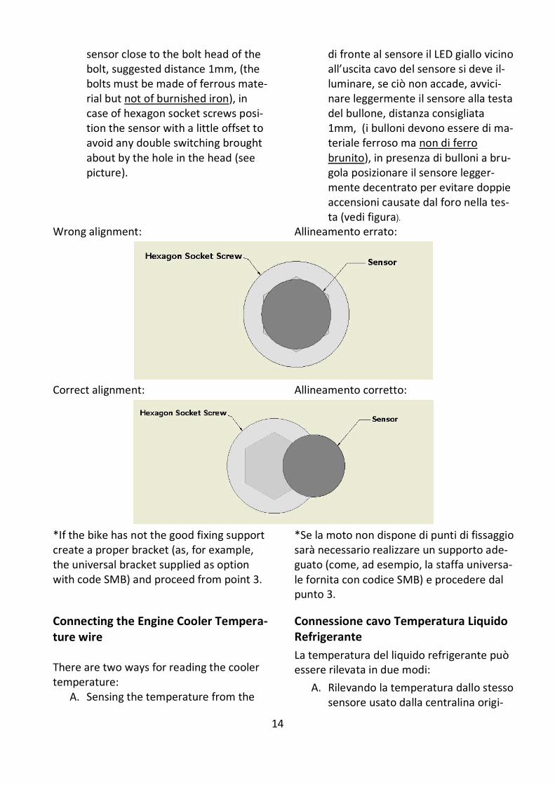
sensor close to the bolt head of the bolt, suggested distance 1mm, (the bolts must be made of ferrous mate-rial but not of burnished iron), in case of hexagon socket screws posi-tion the sensor with a little offset to avoid any double switching brought about by the hole in the head (see picture).
di fronte al sensore il LED giallo vicino all’uscita cavo del sensore si deve il-luminare, se ciò non accade, avvici-nare leggermente il sensore alla testa del bullone, distanza consigliata 1mm, (i bulloni devono essere di ma-teriale ferroso ma non di ferro brunito), in presenza di bulloni a bru-gola posizionare il sensore legger-mente decentrato per evitare doppie accensioni causate dal foro nella tes-ta (vedi figura).
Wrong alignment: Allineamento errato:
Correct alignment: Allineamento corretto:
*If the bike has not the good fixing support create a proper bracket (as, for example, the universal bracket supplied as option with code SMB) and proceed from point 3.
*Se la moto non dispone di punti di fissaggio sarà necessario realizzare un supporto ade-guato (come, ad esempio, la staffa universa-le fornita con codice SMB) e procedere dal punto 3.
Connecting the Engine Cooler Tempera-ture wire There are two ways for reading the cooler temperature:
A. Sensing the temperature from the
Connessione cavo Temperatura Liquido Refrigerante
La temperatura del liquido refrigerante può essere rilevata in due modi:
A. Rilevando la temperatura dallo stesso sensore usato dalla centralina origi-
15
same sensor used by the factory ECU (Engine Control Unit).
B. Sensing the temperature from a ve-hicle sensor not connected to the factory ECU (Engine Control Unit) (ex. Honda, Kawasaki and old gener-ation Ducati) or from the optional Starlane sensor available for 19mm. and 26mm. manifolds.
”A” mode installation:
Find the cooler temperature sensor on the bike, it’s usually connected to 2 wires, one of the wires is directly connected to Ground, the other is connected to the ECU of the bike, connect to this one the White wire of DaVinci-II after cutting the H2O plug on DaVinci-II loom. The connection must be parallel, don’t cut the connection of the factory sensor to the ECU. Insulate with proper tape the black free wire on the H2O cable of DaVinci-II. ”B” mode installation: The optional temperature sensor (code CH2OM10D) must be installed on the cool-er rubber connector between hot water output and the radiator and fixed with two metal strips. Connect the sensor to the fitting 2PIN con-nector on the DaVinci-II loom. On engines fitting a cooler temp. sensor not connected to the ECU it's possible to cut the two ways connector of the DaVinci-II loom and connect the BROWN wire to the sensor signal pin and the BLACK to the sen-sor ground pin.
nale.
B. Rilevando la temperatura dal sensore del veicolo che non sia collegato alla centralina originale (es. moto Honda, Kawasaki e Ducati di vecchia genera-zione) oppure dal sensore opzionale Starlane disponibile per manicotti di diametro 19mm. e 26mm.
Installazione in modalità ”A”:
Individuare sulla moto il sensore per il rile-vamento della temperatura del liquido re-frigerante, in genere è connesso a 2 cavi, uno dei quali è direttamente collegato alla Massa, l’altro è connesso alla centralina del-la moto, collegare a quest’ultimo il cavo Bi-naco dopo aver tagliato il connettore del ca-vo H2O di DaVinci-II. La connessione deve essere in parallelo, non interrompere la connessione tra il sensore e la centralina.
Isolare con apposito nastro il filo Nero che resta libero sul cablaggio di DaVinci-II.
Installazione in modalità ”B”:
Il sensore opzionale (cod. CH2OM10D) deve essere installato sul manicotto di gomma di mandata dell’acqua calda al radiatore attra-verso l’adattatore opzionale (MAN19 e MAN26).
Connettere il sensore all’apposito connetto-re a 2 vie sul cablaggio di DaVinci-II. In caso di connessione al sensore della moto non alimentato dalla centralina originale è possibile tagliare il connettore a due vie del cablaggio di DaVinci-II e collegare il filo MARRONE al pin di segnale del sensore ed il NERO al pin di massa del sensore.
16
Main Screen
The Main Screen shows the most important information in 2 different modes: Street mode and Chrono mode. The system automatically switches to the Chrono Mode as soon as the finish line is triggered. You can also cycle between the
screens by pressing the key.
Schermata principale
La schermata principale mostra le più im-portanti informazioni in due modalità diffe-renti: la modalità Street e quella Crono.
Il sistema passa automaticamente alla mo-dalità Crono quando viene rilevato il pas-saggio sul traguardo. E’ possibile anche cambiare le schermate premendo il tasto
.
To enable the system to record data, se-lect the Chrono screen or, in the Street
screen, press the key for 3 sec-onds until the “REC” label blinks in the bottom of the main screen. In this case press the key once again to stop record-ing.
Perché il sistema registri i dati è necessa-rio che sia selezionata la schermata Cro-no oppure, nella schermata Street, tene-
re premuto per 3 secondi il tasto finchè la scritta “REG.” lampeggia nella parte bassa dello schermo. In quest’ultimo caso sarà necessario ripre-mere il tasto per interrompere la regi-strazione.
Multi-page menu
Apart from the main screen, pressing
you can access the quick functions and the Multi-page menu where to set up the operation parameters and to display the acquired values.
Menu multipagina
Oltre alla schermata principale, premendo
è possibile accedere alle funzioni ra-pide e al Menu Multipagina dove vengono impostati i parametri di funzionamento e indicati i valori acquisiti.
You can move between the Menu lines us-
ing the and keys and access
each page pressing the key, the key will return back to the previous screen.
Ci si può muovere da una linea all’altra del
Menu usando I tasti e e accede-
re ad ogni pagina premendo il tasto , il
tasto farà tornare alla schermata pre-cedente.
17
GPS signal acquisition
The first time the system is switched on af-ter a long time or at a considerable distance from the previous place of operation it might require some minutes to find out the satellites and calculate its position, this phase is called “Cold Start”.
The next time the system will be used in the same location it will find out the satel-lites quickly and you will be able to operate immediately by entering the track within just a few seconds.
To provide for a correct and rapid acquisi-tion before usage, it’s important to position the vehicle in the open where it can easily “see” a good portion of the sky.
Acquisizione del segnale GPS
La prima volta che il sistema viene acceso dopo un lungo periodo o a distanza conside-revole dal luogo di utilizzo precedente po-trebbe richiedere alcuni minuti per indivi-duare i satelliti e calcolare la propria posi-zione, questa fase viene chiamata “Avvio a Freddo”.
La volta successiva che il sistema sarà utiliz-zato nello stesso luogo, esso individuerà i satelliti rapidamente e sarà possibile procedere immediatamente, entrando in pista entro pochi secondi.
Per consentire una rapida e corretta acqui-sizione prima dell’uso è importante posizio-nare il veicolo all’aperto dove possa “vedere” un buona porzione di cielo.
Configuration
Selecting the language
DAVINCI-II menu supports up to 5 lan-guages (English, Italian, German, French and Spanish).
To select the desired language:
Menu: OPTIONS > LANGUAGE
Configurazione
Selezione della lingua
Il menu di DAVINCI-II supporta 5 lingue (Inglese, Italiano, Tedesco, Francese e Spagnolo).
Per selezionare la lingua desiderata :
Menu: OPZIONI > LANGUAGE
Aligning the GPS clock to the local time zone
DAVINCI-II receives the Greenwich time from the GPS system satellites. It’s neces-sary to set the difference between the local time and the Greenwich one.
Menu: GPS > SET LOCAL TIME
Allineamento dell’orologio GPS con il fuso orario
DAVINCI-II riceve l’ora di Greenwich dai satelliti del sistema GPS, è quindi necessario impostare la differenza tra l’ora locale e l’orario di Greenwich.
Menu: GPS > IMPOSTA ORA LOCALE
Setting the lap time Freeze Time
You can set the lap time or the intermediate you wish to remain on the display when triggered (Freeze Time).
Menu: OPTIONS > FREEZE TIME
Impostazione del tempo di visualizzazione a fine giro
È possibile impostare il tempo per cui resta fissa sul display l’indicazione del giro o dell’intermedio appena concluso (Freeze Time).
Menu: OPTIONS > TEMPO DI FREEZE
18
Selection of the units of measurement
Menu: OPTIONS > MAESURING SYSTEM
Selezione delle unità di misura
Menu: OPZIONI > SISTEMA DI MISURA
Setting the RPM reading parameters
Set the number of pulses received for every single revolution of the motor shaft in DAVINCI-II.
If the coil should inductively detect the signal on 2-stroke or 4-stroke engines, with no-phased ignition, set the num-ber of pulses to 1.
If the coil should inductively detect the signal on 4-stroke engines, with phased ignition, set the number of pulses to 0.5.
If the signal is directly detected by the digital signal wire on the original dashboard, set the value according to the system frequency, The correct value is usually 2 on Japanese motor bikes.
Menu: CHANNELS > RPM, SPEED AND GEAR > ENGINE RPM PULSE
Impostazione dei parametri di lettura regime motore
È necessario impostare in DAVINCI-II il numero di impulsi ricevuti per ogni giro di albero motore.
Se il segnale è rilevato induttivamente dalla bobina su motori 2 tempi o 4 tempi a scintilla persa impostare il numero di impulsi a 1.
Se il segnale è rilevato induttivamente dalla bobina su motori 4 tempi con accensione fasata il numero di impulsi deve essere impostato a 0.5.
Se il segnale è rilevato direttamente dal filo di segnale digitale che va al cruscotto originale il valore va impostato in funzione della frequenza del sistema, di solito su moto giapponesi il valore corretto è 2.
Menu: CANALI > RPM, VELOCITA’ E MARCIA > IMPULSI RPM MOTORE
Setting the Shift light
For the Shift Light you can set both, the color and engine RPM threshold at which you wish the A1 and A2 LEDs to turn on.
-To set the RPM threshold:
Menu: ALARMS > SHIFT LIGHT > RPM THRESHOLD
-To set the Color:
Menu: ALARMS > SHIFT LIGHT > LED COLOR
Impostazione Flash di Fuorigiri
E’ possibile impostare a piacere sia il colore che il regime a cui si vuole che si accendano i LED A1 e A2 del Flash di Fuorigiri.
-Per impostare il regime di accensione: Menu: ALLARMI > FLASH DI FUORIGIRI >
SOGLIA RPM -Per impostare il colore:
Menu: ALLARMI > FLASH DI FUORIGIRI > COLORE LED
Setting the LED Bar
It is possible to set at will the the LED bar start RPM, the system will automatically fill the whole bar up to the speed set for the
Impostazione della Barra LED
E’ possibile impostare a piacere il regime da cui si vuole che si accenda la barra LED, il si-stema riempirà in automatico tutta la barra
19
shiftlight.
-To set the RPM threshold:
Menu: ALARMS > LED BAR START RPM
Setting the RPM Bar on LCD
It is possible to set at will the RPM bar max-imum RPM, the system will automatically fill the whole bar up to the speed set.
-To set the maximum RPM:
Menu: ALARMS > GRAPHIC RPM SCALE
fino al regime impostato per il Flash di Fuorigiri.
-Per impostare il regime di accensione: Menu: ALLARMI > INIZIO BARRA LED RPM
Impostazione della Barra RPM sul display
E’ possibile impostare a piacere il regime massimo della barra RPM rappresentata sul display, il sistema riempirà in automatico tutta la barra fino al regime impostato.
-Per impostare il regime massimo: Menu: ALLARMI > SCALA GRAFICA RPM
20
Gear programming
DaVinci-II can specify the gear you have engaged by calculating the continuous ratio between the engine speed and the wheel speed.
Make sure that you have connected the wire intended to read the engine speed
Make sure that the speed reading wire is connected with the wire intended to signal the vehicle speed, from the speed sensor to the connector of the original instrument panel or the Engine Control Unit (This sensor is usually arranged on one of the two wheels or at the output of the gear case).
If the vehicle is not equipped with a speed sensor, but the value is transmitted to the tachometer by means of a mechanical cord, you can mount one of the optional speed sensors available in the catalog.
To enable DaVinci-II to recognize the gears, set the number of engine gears and pro-gram the system after having arranged the motorbike on a stand keeping the rear wheel up (if the speed sensor is intended to detect the speed of the rear wheel) or while running it on the road (if the speed sensor is intended to detect the speed of the front wheel).
To program the recognition of the gears properly, carry out the following opera-tions:
Programmazione delle marce
DaVinci-II è in grado di indicare la marcia in-serita calcolando il continuo rapporto tra il regime motore e la velocità della ruota.
Accertarsi di aver collegato il filo di lettura del regime motore
Accertarsi che il filo di lettura della velocità sia collegato a quello di segnale della velocità del veicolo che va dal sensore velocità al connettore del pannello strumenti originale o alla Centralina Gestione Motore. (Tale sensore è solitamente posizionato su una delle due ruote o in uscita dalla scatola del cambio)
Se il veicolo non è dotato di un sensore velocità ma il valore è trasmesso al tachimetro tramite cordina meccanica è possibile montare uno dei sensori velocità opzionali a catalogo.
Perché DaVinci-II riconosca le marce è necessario impostare il numero di marce del motore e programmare il sistema con la moto su un cavalletto che mantenga sollevata la ruota posteriore (se il sensore velocità rileva la velocità della ruota posteriore) o in strada (se il sensore velocità rileva la velocità della ruota anteriore).
Per programmare correttamente il riconoscimento delle marce eseguire le seguenti operazioni:
Setting up the number of gears of the vehicle
-To set the number of gears of the vehicle:
Menu: CHANNELS > RPM, SPEED AND GEAR > No. OF GEARS
Impostazione del numero di marce del veicolo
-Per impostare il numero di marce del veicolo: Menu: CANALI > RPM, VELOCITA’ E MARCIA
> Num. DI MARCE
21
Gear learning
To learn gears:
Menu: CHANNELS > RPM, SPEED AND GEAR > LEARN GEARS
Start the engine, engage the first gear, ac-celerate to reach a constant speed of about 4000 RPM and press ENTER to store the 1st gear.
After having learnt the 1st gear, you are re-quired to engage the 2nd gear on the dis-play. Engage the 2nd gear and press ACQUIRE while keeping the motor at about 4000 RPM.
Continue the same way until you store the last gear.
In order to verify the correct reading of the needed signals, in the bottom of the screen, the instantaneous values of RPM, Wheel frequency in Hz and the ratio are di-splayed.
Apprendimento dei rapporti
Per apprendere i rapporti:
Menu: CANALI > RPM, VELOCITA’ E MARCIA >APPRENDI MARCE
Avviare il motore, inserire la prima marcia, accelerare fino ad un regime costante di circa 4000 RPM e premere ENTER per me-morizzare il rapporto di 1a marcia.
Una volta appresa la 1a marcia sul display viene richiesto l’inserimento della 2a, inserire quindi la 2a marcia e, mantenendo il motore a circa 4000 RPM, premere ACQUISISCI. Procedere nello stesso modo fino alla memorizzazione dell’ultima marcia.
Al fine di verificare il corretto rilevamento dei segnali necessari, nella parte bassa dello schermo, sono indicati i valori istantanei di RPM, Frequenza Ruota in Hz e il rapporto tra i due valori.
Please Note: Since the gear must be as stable as possible during the learning cycle on the stand, it is recommended to press the rear brake slightly during stor-age so as to reduce drive oscillations to a minimum.
N.B.: Poiché durante l’apprendimento sul cavalletto è necessario avere un rap-porto più stabile possibile si consiglia di premere leggermente il freno posteriore durante la memorizzazione in modo da ridurre al minimo le oscillazioni della tra-smissione.
Attention: Remember that DaVinci-II will constantly calculate the ratio between ENGINE REVOLUTIONS and SPEED. Any action on the clutch may change this ratio and cause a false gear to instantly appear on the display.
Attenzione: Ricordarsi che DaVinci-II calcola continuamente il rapporto tra GIRI MOTORE e VELOCITA’ e ogni intervento sulla frizione può cambiare tale rapporto e far apparire istantanea-mente una marcia non corretta sul di-splay.
Setting the speed reading parameters
To be able to indicate the correct speed, DaVinci-II needs two fundamental infor-mation:
Impostazione dei parametri di lettura della velocità
Per essere in grado di indicare la corretta velocità DaVinci-II ha bisogno di due informazioni fondamentali:
1. The circumference of the wheel on 1. La circonferenza della ruota sulla quale
22
which the speed is measured that will be set from:
Menu: CHANNELS > RPM, SPEED AND GEAR > WHEEL CIRCUMF. mm
Wrap a wire on the wheel at the central line of the tire tread and
measure the wire length in millimeters so to have the exact maximum
circumference.
viene misurata la velocità che dovrà es-sere impostata in:
Menu: CANALI > RPM, VELOCITà E MARCIA > CIRCONF. RUOTA mm
Avvolgere un filo sulla ruota nel punto centrale del battistrada del pneumatico e
misurare la lunghezza in millimetri del filo per avere così l’esatta circonferenza
massima .
2. Number of pulses (for example, the bolts of the brake disk read by the speed sensor, or of gear teeth in bikes with speed sensor inside the gearbox) for each wheel turn. Once set the correct circumference you can find out the correct pulse number by trying different values and comparing the speed shown by DaVinci-II with the speed shown by the original tachometer at a well-defined speed rate.
-To set the pulse number:
Menu: CHANNELS > RPM, SPEED AND GEAR > WHEEL PULSE/REV
2. Il numero di impulsi (ad esempio i bullo-ni del disco del freno rilevati dal sensore velocità, oppure di denti del cambio nelle moto con sensore velocità integrato nella scatola cambio) per ogni giro della ruota. Una volta impostata la corretta circonfe-renza potete trovare il giusto numero di impulsi provando differenti valori e paragonando la velocità mostrata da DaVinci-II con quella indicata dal tachimetro originale ad un determinato regime.
-Per inserire il numero di impulsi:
Menu: CANALI > RPM, VELOCITà E MARCIA > IMPULSI RUOTA.
It’s also possible to acquire automatically the pulse number by using the PULSE LEARNING feature.
Once entered the Pulse Learning mode you just made to make a complete wheel revo-
lution and confirm the value with the key.
IMPORTANT: create a marker on the wheel in order to make a complete
wheel revolution without overpassing 360°, if you make more than 360° repeat
the Pulse Learning from the beginning for the value is incremented indepen-
dently by the rotation direction.
E’ anche possibile acquisire in automatico il numero di impulsi per ogni giro ruota utiliz-
zando la funzione APPRENDI IMPULSI.
Una volta entrati nella modalità Apprendi Impulsi è sufficiente eseguire a mano un giro completo della ruota e confermare il
valore con il tasto .
IMPORTANTE: creare un riferimento sul-la ruota in modo da eseguire un giro
completo senza superare i 360°, in caso si eseguissero più di 360° ripetere
l’apprendimento impulsi dal principio in quanto il valore viene aumentato indi-pendentemente dal senso di rotazione
della ruota.
23
Setting the odometer
You can set the total odometer to the current vehicle mileage:
Menu: CHANNELS > RPM, SPEED AND GEAR > SET ODO TOTAL
The trip odometer can be quickly reset from the main screen by pressing the
key.
Impostazione del contachilometri
E’ possibile impostare i chilometri attuali del veicolo nel contachilometri totale:
Menu: CANALI > RPM, VELOCITà E MARCIA > IMPOSTA ODOMETRO TOTALE
Il contachilometri parziale può essere velocemente azzerato dalla schermata
principale premendo il tasto .
Setting the Warning Lights
To set the warning lights:
Menu: ALARMS
NEUTRAL:
1. As shown on the instructions on the screen, put the gear in neutral posi-tion, move to the “LIGHT ON” line,
and press to set the LIGHT ON threshold.
2. Engage a gear, move to the “LIGHT
OFF” line and press to set the LIGHT OFF threshold.
Impostazione delle Spie
Per impostare le spie:
Menu: ALLARMI
FOLLE:
1. Come mostrato dalle istruzioni sullo schermo, mettere in folle, posizionar-si sulla riga “LUCE ACCESA” e preme-
re per impostare la soglia di
accensione della spia.
2. Inserire una marcia, posizionarsi sulla
riga “LUCE SPENTA” e premere per impostare la soglia di spegnimen-to della spia.
OIL:
1. As shown on the instructions on the screen put the bike in the condition in which the oil alarm is on, for many bikes it’s enough to turn on the key and leave the engine not running, move to the “LIGHT ON” line and
press to set the LIGHT ON threshold. On a few bikes you will need to take away some oil till the factory oil alarm light turns on and then plug the DaVinci-II in and set the LIGHT ON threshold.
2. Add the oil if you took it away or simply run the engine in idle, move to the “LIGHT OFF” line and press
OLIO:
1. Come mostrato dalle istruzioni sullo schermo mettere la moto in condi-zione di accensione della spia dell’olio, per molte moto è sufficiente girare la chiave e mantenere il moto-re spento, posizionarsi sulla riga
“LUCE ACCESA” e premere per impostare la soglia di accensione. Su alcune moto sarà necessario togliere olio finché la spia originale non si ac-cende e poi collegare DaVinci-II e im-postare la soglia “LUCE ACCESA”.
2. Aggiungere olio se è stato tolto o semplicemente accendere il motore in folle, posizionarsi sulla riga “LUCE
24
to set the LIGHT OFF. SPENTA” e premere per impo-stare la soglia di spegnimento.
FUEL:
1. Take away some fuel to leave it at the desired fuel reserve level, turn on the key, wait 1 minute in order to let the fuel sensor timer go on, move to the “RESERVE LEVEL” line
and press to set the reserve threshold.
2. Fill the tank with fuel up to full level, move to the “FULL TANK” line and
press to set the full tank level.
CARBURANTE:
1. Togliere carburante per lasciare la moto con gli esatti litri di riserva de-siderati, girare la chiave in posizione accesa, aspettare 1 minuto in modo che il sensore benzina temporizzato si attivi, posizionarsi sulla riga
“LIVELLO RISERVA” e premere per impostare la soglia di riserva.
2. Riempire il serbatoio fino al pieno, posizionarsi sulla riga “SERBATOIO
PIENO” e premere per impo-stare il livello di serbatoio pieno.
BEAM:
1. As shown on the instructions on the screen turn ON the beam light, move to the “LIGHT ON” line and press
to set the LIGHT ON threshold.
2. Turn OFF the beam light, move to
the “LIGHT OFF” line and press to set the LIGHT OFF.
ABBAGLIANTI:
1. Come mostrato dalle istruzioni sullo schermo accendere i fari abbaglianti, posizionarsi sulla riga “LUCE ACCESA”
e premere per impostare la so-glia di accensione.
2. Spegnere i fari abbaglianti, posizio-narsi sulla riga “LUCE SPENTA” e
premere per impostare la so-glia di spegnimento.
TURN LIGHTS and MIL (FI):
The only setting for the turn lights and FI indicator is the inversion of the signal. If the turn lights alarm stay on when the
they are off, use the REVERSE command to set it correctly.
INDICATORI DI DIREZIONE e SPIA MIL (FI):
L’unica impostazione per la spia degli
indicatori di direzione e la spia FI è l’inversione del segnale. Nel caso in cui la spia degli indicatori di direzione restasse ac-cesa quando gli indicatori sono spenti, utiliz-zare il comando INVERTI per impostarla cor-rettamente.
For each alarm you can also manually modify the activation threshold pre-
viously set by the automatic procedure above mentioned, the activated LED, its
color and totally disable it.
Per ogni allarme è anche possibile varia-re manualmente la soglia di attivazione
che era stata impostata con la procedura automatica sopra indicata, il LED attiva-
to, il relativo colore e disattivarlo.
25
Setting the Cooler Temperature reading
The cooler temperature sensor generates a non-linear signal that can be very different for each brand. On DaVinci-II you can load predefined temperature maps for the most common motorbike brands:
Menu: ALARMS>SELECT H2O TABLE
Impostazione della lettura di Temperatura Liquido Refrigerante
Il sensore temperatura del liquido refrige-rante, al variare della temperatura, genera un segnale non lineare che può essere mol-to diverso in funzione del tipo di sensore. In DaVinci-II sono richiamabili le mappe di se-gnale temperatura solitamente utilizzate dalle più diffuse marche di moto:
Menu: ALLARMI>SELEZIONA TABELLA H2O
If you install the Starlane temperature sen-sor (code CH2OM10D) you will need to se-lect the STARLANE profile in the sensor list.
Se avete installato il sensore temperatura Starlane (codice CH2OM10D) dovrà essere selezionato il profilo STARLANE nella lista dei sensori.
26
How to set the lap triggers on Starlane devices
DAVINCI-II has a lap timer based on the GPS System so it's necessary to let it know the exact position of the Finish Line and the desired Intermediates.
Once the positions have been acquired the lap timer can start counting whenever you cross the Finish Line.
STARLANE Track library
DAVINCI-II is equipped with an internal library of hundreds of circuits with their intermediates (N.B.: the intermediates do not match necessarily official circuit positions) which is constantly being updat-ed with subsequent firmware updates.
When you arrive in a circuit and DAVINCI-II acquires a GPS signal, it will load automatically the track lap triggers
corresponding to its location and you can enter the track without having to
make any setting.
Anyway you can also set your personal finish line and intermediates in 4 different ways on your choice:
A - Activating the automatic finish line po-sitioning function: SAFD-2 (Starlane Auto-matic Finish line Detection).
B - Sending the device the coordinates stored in the track list available in MAAT. See MAAT user guide.
Come impostare i traguardi sui dispositivi Starlane
DAVINCI-II ha un cronometro basato sul sistema GPS, pertanto è necessario fornirgli l’esatta posizione del Traguardo e degli Intermedi desiderati.
Una volta che le posizioni sono state acquisite il cronometro può iniziare il conteggio ogni volta che passate sulla linea del traguardo.
Libreria circuiti STARLANE
DAVINCI-II è dotato di una libreria interna di centinaia di circuiti con i relativi intermedi (N.B.: gli intermedi non corrispondono necessariamente a quelli ufficiali del circuito) che viene continuamente aggiornata con gli aggiornamenti firmware successivi.
Quando si arriva in un circuito e DAVINCI-II acquisisce il segnale GPS,
caricherà automaticamente i traguardi del circuito corrispondente alla propria
posizione e potrete entrare in pista senza dover effettuare alcuna impostazione.
E’ anche comunque possibile impostare traguardi e intermedi personalizzati con 4 procedure diverse a propria scelta:
A - Attivando la funzione di posizionamento automatico del traguardo: SAFD-2 (Starlane Automatic Finish line Detection).
B - Inviando al dispositivo i traguardi archiviati nella lista circuiti disponibile in MAAT. Vedi manuale MAAT.
27
C - Setting the finish line and intermedi-ates on the track map drawn by MAAT after a practice session data down-load. See MAAT user guide.
D - Executing the manual procedure on the device directly on track.
SAFD-2 automatic positioning function
On Starlane last-generation devices you can activate the SAFD-2 function (Starlane Automatic Finish line Detection) which allows the automatic positioning of the finish line on the main straight during the first lap on track and the intermediates on the second lap without requiring any intervention by the driver.
Once executed, the SAFD-2 function,
automatically sets the new lap triggers as active, you will not have to perform it again for subsequent sessions until you will selected a new track as Active Track.
C - Inserendo il traguardo e gli intermedi sulla mappa del circuito rappresentata da MAAT dopo lo scarico dati di una sessione di prova. Vedi manuale MAAT.
D - Con la procedura manuale da effettuarsi direttamente in circuito sul dispositivo.
Funzione di posizionamento automatico SAFD-2
Sui dispositivi Starlane di ultima generazione è possibile attivare la funzione SAFD-2 (Starlane Automatic Finish line Detection) che consente il posizionamento automatico del traguardo sul rettilineo principale durante il primo giro di pista e degli intermedi durante il secondo giro senza richiedere alcuna operazione durante la guida da parte del pilota.
Una volta eseguita, la funzione SAFD-2, imposta automaticamente il nuovo
traguardo e intermedi come attivi, non sarà quindi necessario effettuarla
nuovamente per le sessioni successive finché non si sarà selezionato un nuovo
circuito come Circuito Attivo.
28
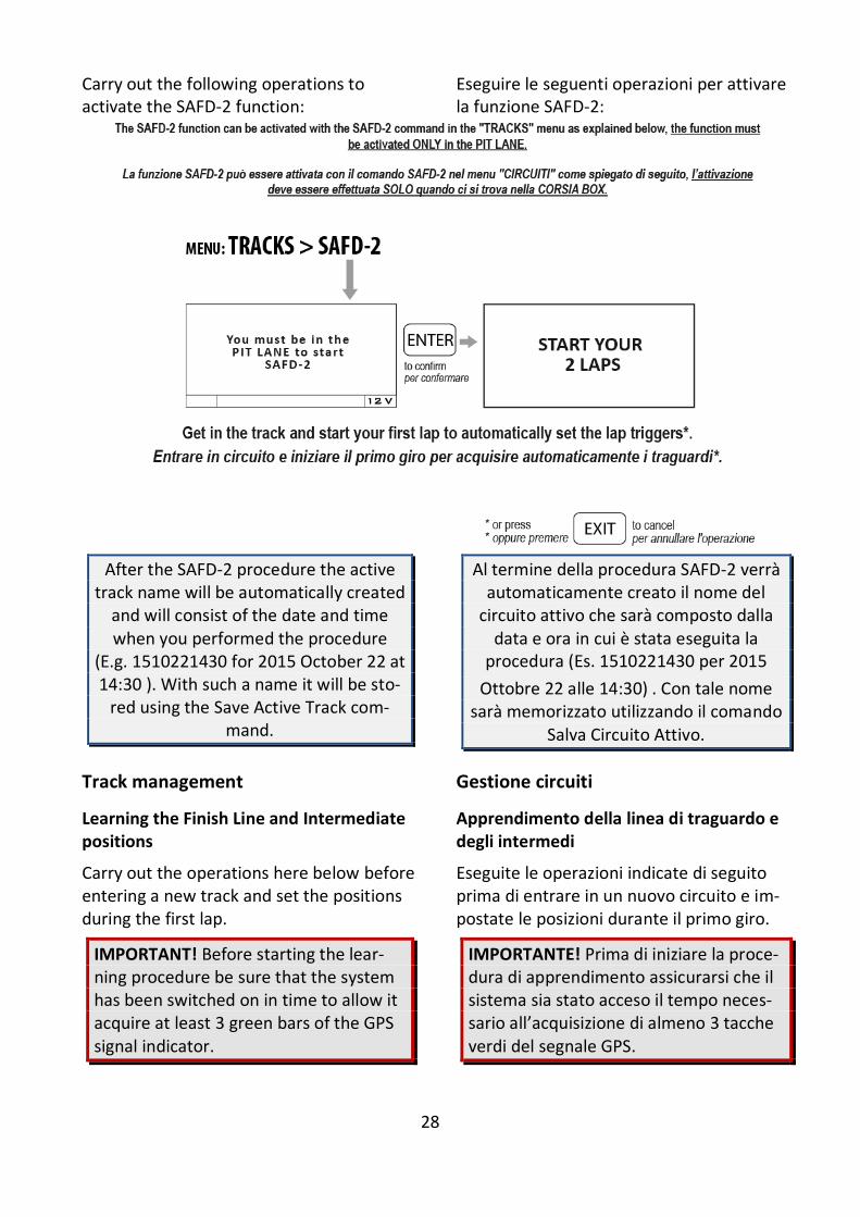
Carry out the following operations to activate the SAFD-2 function:
Eseguire le seguenti operazioni per attivare la funzione SAFD-2:
After the SAFD-2 procedure the active track name will be automatically created
and will consist of the date and time when you performed the procedure
(E.g. 1510221430 for 2015 October 22 at 14:30 ). With such a name it will be sto-
red using the Save Active Track com-mand.
Al termine della procedura SAFD-2 verrà automaticamente creato il nome del
circuito attivo che sarà composto dalla data e ora in cui è stata eseguita la
procedura (Es. 1510221430 per 2015
Ottobre 22 alle 14:30) . Con tale nome sarà memorizzato utilizzando il comando
Salva Circuito Attivo.
Track management
Learning the Finish Line and Intermediate positions
Carry out the operations here below before entering a new track and set the positions during the first lap.
IMPORTANT! Before starting the lear-ning procedure be sure that the system has been switched on in time to allow it acquire at least 3 green bars of the GPS signal indicator.
Gestione circuiti
Apprendimento della linea di traguardo e degli intermedi
Eseguite le operazioni indicate di seguito prima di entrare in un nuovo circuito e im-postate le posizioni durante il primo giro.
IMPORTANTE! Prima di iniziare la proce-dura di apprendimento assicurarsi che il sistema sia stato acceso il tempo neces-sario all’acquisizione di almeno 3 tacche verdi del segnale GPS.
29
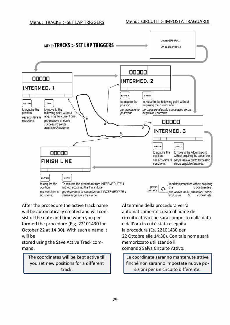
Menu: TRACKS > SET LAP TRIGGERS Menu: CIRCUITI > IMPOSTA TRAGUARDI
After the procedure the active track name will be automatically created and will con-sist of the date and time when you per-formed the procedure (E.g. 22101430 for October 22 at 14:30). With such a name it will be stored using the Save Active Track com-mand.
The coordinates will be kept active till you set new positions for a different
track.
Al termine della procedura verrà automaticamente creato il nome del circuito attivo che sarà composto dalla data e dall’ora in cui è stata eseguita la procedura (Es. 22101430 per 22 Ottobre alle 14:30). Con tale nome sarà memorizzato utilizzando il comando Salva Circuito Attivo.
Le coordinate saranno mantenute attive finché non saranno impostate nuove po-
sizioni per un circuito differente.
30
Storing the coordinates of the Finish Line and Intermediate positions
Memorizzazione delle coordinate di Traguardo e Intermedi
Once you have learnt the positions, you can store them in a list of 16 favorite Tracks.
Menu: TRACKS > SAVE ACTIVE TRACK
Choose one of the free positions between 01 e 16.
Una volta che sono state apprese le posizioni è possibile memorizzarle in una lista di 16 circuiti favoriti.
Menu: CIRCUITI > SALVA CIRCUITO ATTIVO
Scegliere una delle posizioni libere tra 01 e 16.
Loading the track coordinates
You can recall the Finish Line and Interme-diate positions of a track that have already been stored or choose them in the custom-ized track list sent from the PC
(see MAAT user guide).
Menu: TRACKS > SELECT ACTIVE TRACK
Richiamare le coordinate di un circuito
È possibile richiamare le posizioni di tra-guardo e intermedi di un circuito preceden-temente memorizzato oppure sceglierle dalla lista personalizzata dei circuiti inviata dal computer
(vedi manuale utente MAAT).
Menu: CIRCUITI > SELEZIONA CIRCUITO ATTIVO
Clearing the personal track list
-To clear the personal track list in memory:
Menu: TRACKS > CLEAR TRACK LIST
This command will not clear the Starlane track list which can’t be removed.
Cancellare la lista circuiti personale
-Per cancellare la lista di circuiti personale in memoria:
Menu: CIRCUITI > AZZERA LISTA CIRCUITI
Questo comando non cancellerà la lista cir-cuiti STARLANE che non può mai essere ri-
mossa.
Resetting the active track
-To reset the current active track without removing it from the track list in case you stored it before:
Menu: TRACKS > RESET ACTIVE TRACK
Annullare il circuito attivo
-Per annullare il circuito attualmente impo-stato come attivo senza rimuoverlo dalla lista circuiti se vi fosse stato memorizzato:
Menu: CIRCUITI > RESETTTA CIRCUITO ATTIVO
DAVINCI-II will automatically select the nearest track on the basis of its position.
Automatic track recognition
When DAVINCI-II is powered on and acquires the satellites near one of the tracks stored in the track list, it will automatically display a confirmation screen
DAVINCI-II evidenzierà automaticamente il circuito più vicino in base alla propria posi-zione.
Riconoscimento automatico del circuito
Quando DAVINCI-II viene acceso e acquisi-sce i satelliti nelle vicinanze di un circuito presente nella lista di quelli memorizzati,
31
that allows to load the specific finish line information for that track.
To disable this function just set OFF the LIST NEAR TRACKS feature in the TRACKS menu.
comparirà automaticamente una schermata di conferma per l’utilizzo dei traguardi disponibili in memoria per quel circuito.
Se si vuole disattivare tale funzione è sufficiente impostare come OFF la funzione
PROPONI CIRCUITI VICINI nel menu CIRCUITI.
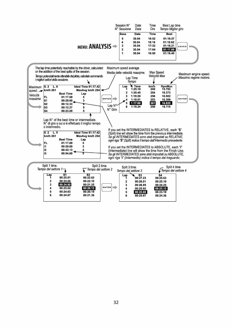
Analysis of the stored times
DAVINCI-II stores the times of 999 laps di-vided into 99 sessions whenever you power the lap timer off and on, a new session is automatically created.
-To display the list of the acquired sessions:
Menu: ANALYSIS
Select the desired session with by the
and buttons and press to see details.
Analisi dei tempi memorizzati
DAVINCI-II memorizza i tempi di 999 giri suddivisi in 99 sessioni. Ogni volta che il cronometro viene spento e riattivato viene creata una nuova sessione automaticamen-te.
-Per visualizzare la lista delle sessioni acquisite:
Menu: ANALISI
Selezionare la sessione desiderata tramite i
tasti e e premere per vederne i dettagli.
32
33
Managing the Hour Meters
In order to allow an easy and sharp engine maintenance, DaVinci-II also integrates two separate Hour Meters.
The Hour Meters are activated by the en-gine speed signal and by the GPS speed, this solution can provide for perfect meas-uring even if the tacho cable has not been connected.
-To check the Hour Meters:
Menu: MEMORY > SHOW HOUR METERS
Gestione dei Contaore
Per consentire una semplice e puntuale ma-nutenzione del motore, DaVinci-II integra anche due Contaore separati.
I Contaore sono attivati sia dal segnale re-gime motore che dalla velocità GPS, questa soluzione consente la perfetta misurazione anche se il cavo lettura regime motore non è stato collegato.
-Per verificare i valori dei contaore:
Menu: MEMORIA > MOSTRA CONTAORE
Memory Management
Session recording
The device will automatically start record-ing a new session whenever the engine speed goes over 3000 Rpm or the GPS speed goes over 25 Km/h (15.5 mph) for at least 3 secs.
Recording will automatically stop if the engine speed is = 0 rpm and the GPS
speed is below 10 Km/h (6.2 mph) for at least 5 seconds.
Gestione della memoria
Registrazione delle sessioni
Il dispositivo comincerà a registrare auto-maticamente una nuova sessione ogni volta che il regime motore supera i 3000 RPM o la velocità GPS supera i 25 Km/h per almeno 3 secondi.
La registrazione si ferma automatica-mente se il regime motore scende a 0 e la velocità GPS è inferiore a 10 Km/h per
almeno 5 secondi.
While DAVINCI-II is recording the REC label blinks at the bottom of the screen.
NOTE: in order to void the memorization of useless sessions, DAVINCI-II deletes automatically every session of duration
below 1 minute.
Mentre DAVINCI-II è in registrazione la scritta REG. lampeggia alla base del display.
NOTA: per evitare che vengano memo-rizzate sessioni inutili, DAVINCI-II cancel-
la automaticamente ogni sessione di durata inferiore a 1 minuto.
34
Manual recording
If you want to record some data without starting the engine, you can also activate the manual data recording feature by
keeping pressed for 2 seconds the button.
DAVINCI-II will start recording data until
is kept pressed a second time to stop recording.
NB: due to the system automatic activa-tion of the recording based on GPS speed and RPM, therefore it is not
necessary to activate manual recording to acquire data when starting the
session on track.
Registrazione manuale
Se si vuole effettuare una registrazione ma-nuale di prova senza accendere il motore,
è possibile mantenere premuto il bottone
per 2 secondi. DAVINCI-II inizierà a
registrare i dati finché il pulsante non sarà mantenuto premuto una seconda volta per fermare la registrazione.
N.B.: poichè il sistema ha comunque l’attivazione automatica della
registrazione in base a velocità GPS e RPM, non è necessario
attivare la registrazione manuale per acquisire le sessioni quando si entra in
pista.
Checking the memory in use
-To check the memory usage:
Menu: MEMORY > MEMORY STATUS
Verifica della memoria utilizzata
-Per visualizzare l’utilizzo della memoria:
Menu: MEMORIA > STATO DELLA MEMORIA
Memory clearing
DAVINCI-II will enable you to clear the memory of the session you last stored:
Menu: MEMORY > CLEAR LAST SESSION
Cancellazione della memoria
DAVINCI-II consente di cancellare la memo-ria dell’ultima sessione memorizzata.
Menu: MEMORIA > CANCELLA ULTIMA SESSIONE
or the complete session list:
Menu: MEMORY > CLEAR ALL SESSIONS
oppure di tutta la lista di sessioni:
Menu: MEMORIA > CANCELLA TUTTE LE SESSIONI
Memory Formatting
You can completely format the DAVINCI-II Memory by executing the fol-lowing operations:
Menu: MEMORY > FORMAT MEMORY
Formattazione della Memoria
È possibile formattare totalmente la Memoria di DAVINCI-II eseguendo le operazioni indicate di seguito:
Menu: MEMORIA > FORMATTA MEMORIA
If you only wish to clear the Memory of the Sessions you have already downloaded, you can do it by using the CLEAR DOWNLOADED
SESSIONS.
Se si vuole cancellare solo la Memoria delle Sessioni già scaricate è possibile farlo con il comando CANCELLA SESSIONI SCARICATE.
35
Computer connections
DaVinci can be connected to a computer via a high speed USB cable or Bluetooth wire-less and WiFi.
The connection is necessary for:
1. Set the dashboard parameters.
2. Import on a computer and save on a file the parameters you have previ-ously set directly from the dash-board keyboard.
3. Download the data acquired during the track sessions to analyze them by means of the MAAT software (for this operation it is recommended to use the USB cable in order to drasti-cally reduce the data download time).
DaVinci-II has been designed to be also supplied directly by the USB cable for an easy setup and data download even when it is not installed on the vehicle.
Just connect the USB cable to the com-puter and the dashboard will be active with the basic features, in this mode the LEDs are not activated and the backlight is set to low intensity in order to reduce the power consumption,
Collegamenti con il computer
DaVinci può essere collegato al computer sia con cavo USB ad alta velocità che in mo-dalità senza fili Bluetooth e WiFi.
Il collegamento è necessario per:
1. Impostare i parametri del cruscotto.
2. Importare su computer e salvare su file i parametri precedentemente im-postati direttamente dalla tastiera del cruscotto.
3. Scaricare i dati acquisiti durante le sessioni in pista per poi analizzarli con il software MAAT (per questa operazione è consigliabile utilizzare il cavo USB in quanto consente di ri-durre notevolmente il tempo di scari-co dati).
DaVinci-II è stato progettato per essere anche alimentato direttamente dal cavo USB per consentirne la comoda imposta-zione e lo scarico dei dati anche quando non è installato sul veicolo.
E’ sufficiente connettere il cavo USB al computer e il cruscotto si attiverà con le funzioni base, in questa modalità vengo-no attivati LED e la retroilluminazione viene mantenuta ad un basso livello per ridurre i consumi.

36
USB cable connection
For the USB connection, install the MAAT software that you can download from www.starlane.com.
When the USB cable is plug into the PC, DaVinci-II will be seen as a normal USB
flash memory unit, in order to avoid any malfunction, never copy or remove any
file manually on the DaVinci-II removable unit.
If an automatic Windows message ap-pears asking you to correct the remova-ble drive, close the warning without ma-
king any corrections.
Connessione con cavo USB
Per effettuare la connessione con cavo USB, installare il software MAAT scaricabile dal sito www.starlane.com.
Quando il cavo USB viene collegato al computer, DaVinci-II viene visto come una normale memoria flash USB, onde evitare anomalie nel funzionamento è
importante non copiare o rimuovere mai alcun file manualmente dall’unità
removibile DaVinci-II.
Se compare un messaggio automatico di Windows che richiede di correggere
l’unità removibile, chiudere l’avviso sen-za effettuare alcuna correzione.
Configuring the Bluetooth connection
To activate the Bluetooth communication between PC and device proceed as follows:
1. Make sure that the drivers provided by the manufacturer of the computer's Bluetooth device are correctly installed on your PC.
2. Power on DaVinci-II and keep it not more than 2-3 metres from the PC.
3. Click on the "Devices" icon in the MAAT software menu bar and follow the instructions in the software manual to perform the DaVinci-II Pairing.
Impostazione della connessione Bluetooth
Per attivare la comunicazione Bluetooth tra il PC e lo strumento procedere come segue:
1. Verificare che sul proprio PC siano cor-rettamente installati i driver forniti dal produttore del dispositivo Bluetooth del computer.
2. Accendere DaVinci-II e posizionarlo entro 2-3 metri dal PC.
3. Cliccare sull'icona “Dispositivi” nella barra menu del software MAAT e seguire le indicazioni del manuale del software per effettuare il Pairing di Da-Vinci-II.
Updating the DAVINCI-II firmware
The software installed inside DAVINCI-II and intended to manage all functionalities is referred to as Firmware.
You can update the firmware when new versions with additional implementations and/or improvements are made available by Starlane.
Aggiornamento del firmware di DAVINCI-II
Il software installato all’interno di DAVINCI-II e che ne gestisce tutte le funzionalità ha il nome di Firmware.
È possibile aggiornare il Firmware quando ne siano rese disponibili da Starlane nuove versioni con implementazioni aggiuntive e/o migliorie.
37
Checking the Firmware version installed
The Firmware version installed is displayed at the bottom of the splash screen of your DAVINCI-II.
Verifica della versione di Firmware installata
Nella parte bassa della schermata di avvio del vostro DAVINCI-II è indicata la versione di Firmware installata.
You can also check the exact model, the software version (Firmware) and the serial number by accessing the System Info screen.
È anche possibile verificare l’esatto modello, versione di software (Firmware) e numero di serie accedendo alla schermata System Info.
Downloading the update
Check on the technical support page of the www.starlane.com web site whether more up-to-date Firmware or MAAT versions (the version number is higher) are available for your device.
Follow the procedure described by the MAAT software manual to download and install the latest Firmware update.
Scarico dell’aggiornamento
Verificare sulla pagina di supporto tecnico del sito www.starlane.com la disponibilità di versioni più aggiornate (numero di versione più alto) del firmware per il vostro dispositi-vo nonché la relativa versione aggiornata di MAAT.
Seguire la procedura indicata sul manuale del software MAAT per eseguire corretta-mente l’aggiornamento all’ultima versione di Firmware.
Device name
You can rename your DAVINCI-II by using a name of your choice:
1-Start the MAAT software.
3-From the “Device” menu, select “Rename”, type the name you wish and
press OK.
Nome del dispositivo
E' possibile rinominare il vostro DAVINCI-II con un nome a vostra scelta:
1-Lanciare il software MAAT.
2-Nel menu “Dispositivo”, selezionare “Rinomina”, digitare il nome desiderato e
premere OK.
The lap timer will automatically acquire the new name.
Loading tracks
You can load the finishing lines of the best-known tracks made available in the MAAT software onto DAVINCI-II:
1-Start the MAAT software.
2-Follow the instructions you can find in the MAAT software manual for the manage-ment of tracks.
Il cronometro acquisirà automaticamente il nuovo nome.
Caricamento dei circuiti
E' possibile caricare in DAVINCI-II i traguardi dei circuiti più famosi disponibili nel software MAAT:
1-Lanciare il software MAAT.
2-Seguire le indicazioni di gestione dei circuiti nel manuale del software
MAAT.
38
From now on, you can select the track you wish from the menu:
TRACKS > SELECT ACTIVE TRACK
Da questo momento sarà possibile selezionare il circuito desiderato dal menu:
CIRCUITI > SELEZIONARE CIRCUITO ATTIVO
Track export
If you have acquired the coordinates of the finishing lines and intermediates directly on the track by following the manual procedure, you can export the list of the tracks stored on the instrument in the computer:
1- Start the MAAT software.
2-Follow the instructions you can find in the MAAT software manual for the manage-ment of tracks.
Esportazione dei circuiti
Se si sono acquisite le coordinate dei traguardi e degli intermedi direttamente in pista con la procedura manuale, è possibile esportare la lista dei circuiti memorizzati sullo strumento nel computer:
1-Lanciare il software MAAT.
2-Seguire le indicazioni di gestione dei circuiti nel manuale del software MAAT.
39
Open Circuit and Performance Test Functionality
DaVinci-II can be used also on open circuits and in acceleration tests.
The system can manage up to 4 different modes for time acquisition:
CLOSED: CLOSED CIRCUIT detection of times and 3 intermediates on closed circuits, where the end of lap is the same as the start of the next one.
OPEN LAUNCHED: OPEN CIRCUIT WITH LAUNCHED START
detection of times and 2 intermediates on open circuits, where the start line is different from the finish line and the vehicle crosses the start line when already moving, i.e. not standing still thereon.
OPEN STILL: OPEN TRACK WITH STILL START detection of times and 3 intermediates on open circuits, where the start line is different from the finish line and - when starting - the vehicle is standing still on the start line.
PERFORMANCE TEST: ACCELERATION TEST detection of times, speeds and distances on 8 different user-settable thresholds.
Mode selection
You can select the mode you wish:
Menu: MODE > CIRCUIT TYPE
Funzionalità di Circuito Aperto e Performance Test
DaVinci-II consente l'utilizzo del dispositivo anche su circuiti aperti e nelle prove di accelerazione.
Il sistema è in grado di gestire fino a 4 modalità diverse per l'acquisizione dei tempi:
CIRCUITO CHIUSO: CIRCUITO CHIUSO rilevamento di tempi e 3 intermedi su circuiti chiusi, dove quindi la fine di un giro corrisponde all'inizio del successivo.
CIRCUITO APERTO LANCIATO: CIRCUITO APERTO CON PARTENZA LANCIATA rilevamento del tempo e 2 intermedi su circuiti aperti, dove quindi la linea di partenza è differente dalla linea di arrivo e il veicolo transita sulla linea di partenza già in movimento, senza partire da fermo sulla stessa.
CIRCUTIO APERTO DA FERMO : CIRCUITO APERTO CON PARTENZA DA FERMO rilevamento del tempo e 3 intermedi su circuiti aperti, dove quindi la linea di partenza è differente dalla linea di arrivo e il veicolo parte da fermo in corrispondenza della linea di partenza.
TEST DI PRESTAZIONE: TEST DI ACCELERAZIONE rilevamento di tempi, velocità e distanze su 8 diverse soglie impostabili dall'utente.
Selezione della modalità
E' possibile selezionare la modalità desiderata:
Menu: MODALITA’ > TIPO CIRCUITO

40
Learn the finish lines and intermediates in the OPEN LAUNCHED mode
Once selected the OPEN L mode perform the following procedure for the 4 points you have indicated (Start Line, Intermediate1, Intermediate2, Finish Line) while going along the track in question:
Menu: TRACKS > SET LAP TRIGGERS
Apprendimento dei traguardi e degli intermedi nella modalità CIRCUITO APERTO LANCIATO
Dopo aver selezionato la modalità CIRCUITO APERTO LANCIATO eseguire la seguente procedura per i 4 punti indicati (Linea di Partenza, Intermedio1, Intermedio2, Traguardo) percorrendo il circuito interessato:
Menu: CIRCUITI > IMPOSTA TRAGUARDI
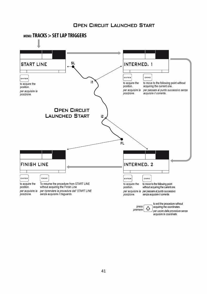
41

42
Learn the finish lines and intermediates in the OPEN STILL mode
Once selected the OPEN S mode perform the following procedure for the 3 points you have indicated (Intermediate1, Inter-mediate2, Intermediate3, Finish Line) while going along the track in question:
Menu: TRACKS > SET LAP TRIGGERS
Apprendimento dei traguardi e degli intermedi nella modalità CIRCUITO APERTO DA FERMO
Dopo aver selezionato la modalità CIRCUITO APERTO DA FERMO eseguire la seguente procedura per i 3 punti indicati (Intermedio1,Intermedio2, Intermedio3, Traguardo) percorrendo il circuito interessato:
Menu: CIRCUITI > IMPOSTA TRAGUARDI
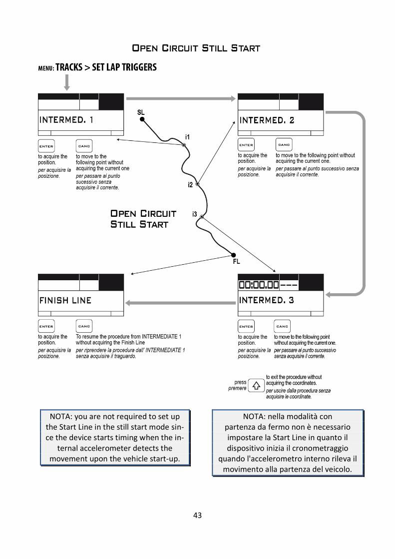
43
NOTA: you are not required to set up the Start Line in the still start mode sin-ce the device starts timing when the in-
ternal accelerometer detects the movement upon the vehicle start-up.
NOTA: nella modalità con partenza da fermo non è necessario impostare la Start Line in quanto il dispositivo inizia il cronometraggio
quando l'accelerometro interno rileva il movimento alla partenza del veicolo.
44
Accelerometer sensitivity set-up
According to the type of vehicle, you may be required to set up various accelerometer sensitivity thresholds for detection at the start-up.
For correct operation, the instrument must be secured onto the vehicle ac-cording to instructions and not hand-
held or placed on mobile parts.
To choose the correct sensitivity of the accelerometer:
Menu: MODE > ACCELEROTMETER SENSITIVITY
Important: carry out some start tests on various sensitivity levels to find out the best compromise to start timing and to avoid timing unintentionally as a result
of slight vibrations or movements of the vehicle.
Impostazione della sensibilità dell'accelerometro
A seconda del tipo di veicolo può essere necessario impostare diverse soglie di sensibilità dell'accelerometro per il rilevamento della partenza.
Per il corretto funzionamento, lo strumento deve essere fissato sul
veicolo come da istruzioni e non tenuto in mano o su
parti mobili.
Per scegliere la corretta sensibilità dell'accelerometro:
Menu: MODALITA’ > SENSIBILITA’ ACCELEROMETRO
Importante: effettuare alcune prove di partenza su vari livelli di sensibilità in modo da trovare il compromesso migliore per l'avvio del cronometraggio senza che questo avvenga indesiderata-mente per via di vibrazioni o piccoli movimenti del veicolo.
Whenever you are in the main screen page, the following message will appear on the display before the start-up:
PRESS ENTER TO START
at this time, the accelerometer is deactivated to avoid any false start when the vehicle is moving. After stopping the vehicle on the start line,
press to activate the accelerometer; the system will wait for the vehicle to move and activate timing automatically.
To abort the test
press .
Quando ci si trova sulla schermata principale, prima della partenza, sul display compare il seguente messaggio:
PREMERE ENTER PER INIZIARE
in questo momento l'accelerometro è disattivato per evitare false partenze durante i movimenti del veicolo. Una volta fermato il veicolo sulla linea di
partenza, premere per attivare l'accelerometro; il sistema resta quindi in attesa di ogni successivo movimento del veicolo che attiverà il cronometraggio automaticamente.
Per fermare il test
prematuramente premere .
45
Acceleration test in the Performance Test mode
After calibrating the accelerometer accord-ing to the previous paragraph, you can car-ry out an acceleration test on 4 speed and distance user-settable thresholds.
Test di accelerazione con la modalità Test di Prestazione
Una volta effettuata la calibrazione dell'accelerometro, come da paragrafo precedente, è possibile effettuare test di accelerazione su 4 soglie di velocità e di distanza impostabili a piacimento.
Set the speed and distance thresholds you wish:
Menu: MODE > PERFORMACE TEST > THRESHOLDS
Click on each speed (SP) and distance (D) threshold to set the desired value.
Impostare le soglie di velocità e distanza desiderate:
Menu: MODALITA’ > SOGLIE TEST DI PRESTAZIONE
Cliccare su ogni soglia di velocità (SP) e di distanza (D) per impostare il valore deside-rato.
Carry out the Acceleration Test
Once selected the PT mode position yourself on the start line after displaying the following main screen page:
Esecuzione del Test di Accelerazione
Dopo aver selezionato la modalità PT posizionarsi sulla linea di partenza con lo strumento nella seguente schermata principale:
PRESS ENTER TO START PREMERE ENTER PER INIZIARE
at this time, the accelerometer is deactivated to avoid any false start when the vehicle is moving.
After stopping the vehicle on the start line,
press to activate the accelerometer; the system will wait for the vehicle to move and activate timing automatically.
Once the vehicle has started, the display will show time, instantaneous speed and all the speed and distance thresholds in up-dated in real time as soon as they are reached.
To abort the test
press .
in questo momento l'accelerometro è disattivato per evitare false partenze durante i movimenti del veicolo.
Una volta fermato il veicolo sulla linea di
partenza, premere per attivare l'acce-lerometro; il sistema resta quindi in attesa di ogni successivo movimento del veicolo che attiverà il cronometraggio automaticamente. Dopo la partenza del veicolo, sul display, appariranno il tempo, la velocità istantanea
e tutte le soglie di velocità e distanza aggiornate in tempo reale al raggiungimento delle stesse.
Per fermare il test
prematuramente premere .
46
Activation from remote button
In car applications in which DAVINCI-II can’t be hand operated, you can set an analog or alarm input to connect it to an external button:
Menu: MODE > TRIGGER INPUT
1- Select in the drop-down menu the analog channel that you connected to the button (for example the TPS input).
2- Click on ENABLE.
3- Keep pressed the button and click SET ON.
4- Release the button and press SET OFF.
5- Press to confirm.
Once the input has been configured you can use the remote button to:
Activate the accelerometer in still starts (by pressing the button once).
Abort the test (by pressing the
button twice and confirming the message box with another pressing).
Note: the button of the vehicle will have to output a variation of voltage between
0V and 5V.
Attivazione da pulsante remoto
In applicazioni su auto in cui DAVINCI-II non fosse raggiungibile con la mano, è possibile configurare un ingresso analogico o di al-larme per collegarlo ad un pulsante esterno:
Menu: MODALITA’ > INGRESSO PULSANTE
1- Selezionare nel menu a tendina il canale analogico a cui è stato collegato il pulsante (per esempio l’ingresso TPS).
2- Cliccare su ABILITATO.
3- Mantenere premuto il pulsante e cliccare su ATTIVA.
4- Rilasciare il pulsante e premere DISATTIVA.
5- Premere per confermare.
Una volta configurato l’ingresso sarà possibile utilizzare il pulsante remoto per:
Attivare l’accelerometro nelle partenze da fermo (premendo il pulsante 1 volta).
Fermare la prova prematuramente (premendo 2 volte il pulsante e dando conferma al messaggio con una successiva pressione).
Nota: il pulsante del veicolo dovrà dare in uscita una variazione di
tensione compresa tra 0V e 5V.
Analysis of acquired data
If you access the analysis mode, the ses-sions made on the open track will be shown in the Best column and marked as OC, whereas Performance Test ones are marked as PT.
Carry out the following operations to dis-play the data acquired in an Open Circuit test:
Analisi dei dati acquisiti
Entrando nella modalità di analisi, le sessio-ni effettuate su circuito aperto saranno indicate nella colonna Best con la sigla OC, mentre quelle di Performance Test con la sigla PT.
Eseguire le seguenti operazioni per visualizzare i dati acquisiti in un test su Circuito Aperto:
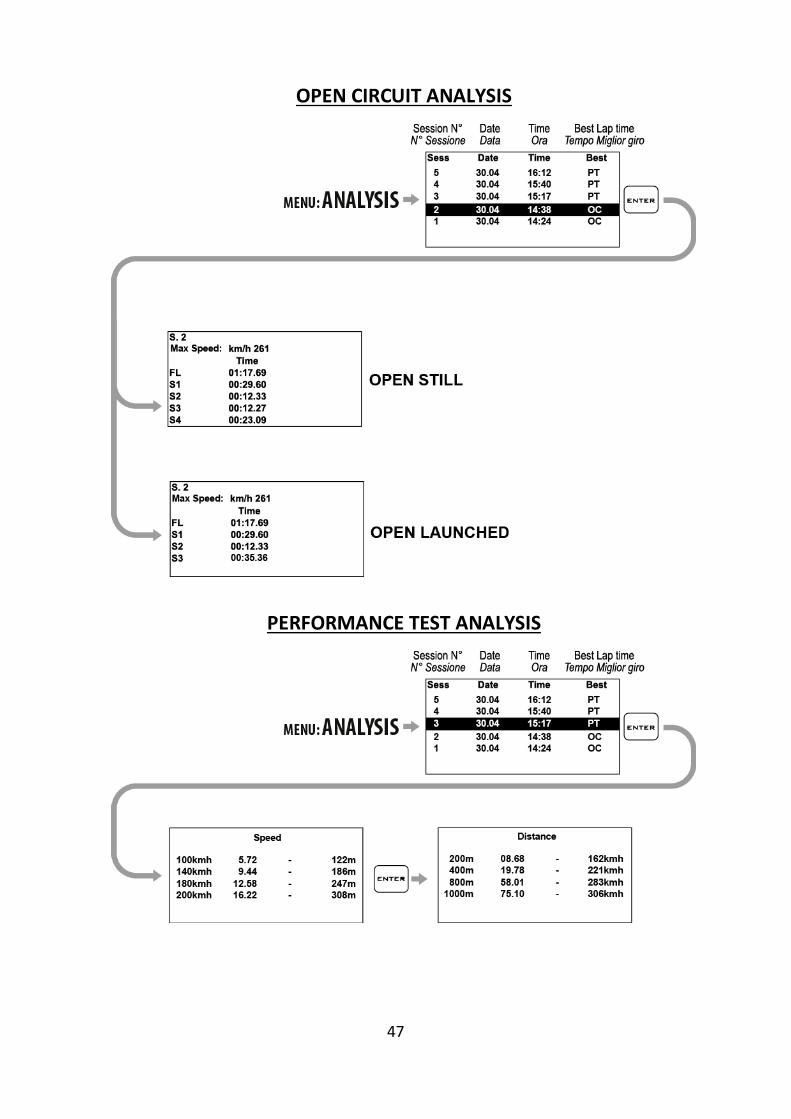
47
OPEN CIRCUIT ANALYSIS
PERFORMANCE TEST ANALYSIS
48
Calibrating TPS signal, managing WID wireless
modules on DAVINCI-II S and
Advanced functions on DAVINCI-II R
Calibrazione segnale TPS, gestione moduli wireless WID
su DAVINCI-II S e
Funzioni avanzate di
DAVINCI-II R
49
Acquisition channels managed by DAVINCI-II
DAVINCI-II can acquire the data both direct-ly from its loom or from sensors connected through WID optional expansion modules .
Channels acquired by DaVinci-II S
Laptime with intermediates
GPS Speed
GPS Trajectroies
RPM
Engaged Gear
TPS (Throttle position sensor)
Lean Angle
Lateral and Longitudinal Accelerations
All channels available on connected optional WID modules.
Channels acquired by DaVinci-II R:
Laptime with intermediates
GPS Speed
GPS Trajectroies
RPM
Engaged Gear
Lean Angle
Lateral and Longitudinal Accelerations
4 Analog channels at 500Hz high fre-quency (Eg. For TPS, Suspensions, Brake Pressure, etc.)
All channels available on connected optional WID modules.
All channels managed by the configuration of the specific loom connected to the data line of the ECU or configured on customized CAN BUS line.
From the CHANNELS menu you can access the list of available channels (depending
Canali acquisizione gestiti da DAVINCI-II
DAVINCI-II può acquisire i dati sia diretta-mente dal cablaggio sia dai sensori collegati attraverso moduli di espansione WID opzionali.
Canali acquisiti da DaVinci-II S:
Tempo sul giro con intertempi
Velocità GPS
Traiettorie GPS
RPM
Marcia inserita
TPS (Apertura Acceleratore)
Angolo di Piega
Accelerazioni Laterale e Longitudinale
Tutti i canali disponibili su eventuali
moduli WID opzionali connessi.
Canali acquisiti da DaVinci-II R:
Tempo sul giro con intertempi
Velocità GPS
Traiettorie GPS
RPM
Marcia inserita
Angolo di Piega
Accelerazioni Laterale e Longitudinale
4 Cannali analogici ad alta frequenza 500Hz (Es. per TPS, Sospensioni, Pressione Freno, ecc.)
Tutti i canali disponibili su eventuali
moduli WID opzionali connessi.
Tutti i canali gestiti dalla configurazione del cablaggio specifico collegato alla linea dati della ECU o configurati su linea CAN BUS personale.
Dal menu CANALI è possibile accedere alla lista dei canali disponibili (in funzione anche
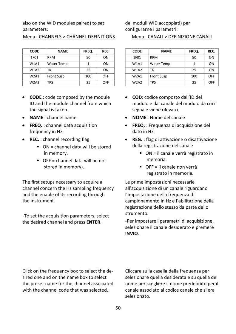
50
also on the WID modules paired) to set parameters:
Menu: CHANNELS > CHANNEL DEFINITIONS
dei moduli WID accoppiati) per configurarne i parametri:
Menu: CANALI > DEFINIZIONE CANALI
CODE NAME FREQ. REC.
1F01 RPM 50 ON
W1A1 Water Temp 1 ON
W1A2 TK 25 ON
W2A1 Front Susp 100 OFF
W2A2 TPS 25 OFF
CODE NAME FREQ. REC.
1F01 RPM 50 ON
W1A1 Water Temp 1 ON
W1A2 TK 25 ON
W2A1 Front Susp 100 OFF
W2A2 TPS 25 OFF
CODE : code composed by the module ID and the module channel from which the signal is taken.
NAME : channel name.
FREQ. : channel data acquisition frequency in Hz.
REC. : channel recording flag
ON = channel data will be stored in memory.
OFF = channel data will be not stored in memory).
COD: codice composto dall’ID del modulo e dal canale del modulo da cui il segnale viene rilevato.
NOME : Nome del canale
FREQ. : Frequenza di acquisizione del dato in Hz.
REG. : flag di attivazione o disattivazione della registrazione del canale
ON = il canale verrà registrato in memoria.
OFF = il canale non verrà registrato in memoria.
The first setups necessary to acquire a channel concern the Hz sampling frequency and the enable of its recording through the instrument.
-To set the acquisition parameters, select the desired channel and press ENTER.
Le prime impostazioni necessarie all’acquisizione di un canale riguardano l’impostazione della frequenza di campionamento in Hz e l’abilitazione della registrazione dello stesso da parte dello strumento.
-Per impostare i parametri di acquisizione, selezionare il canale desiderato e premere INVIO.
Click on the frequency box to select the de-sired one and on the name box to select the preset name for the channel associated with the channel code that was selected.
Cliccare sulla casella della frequenza per selezionare quella desiderata e su quella del nome per scegliere il nome predefinito per il canale associato al codice canale che si era selezionato.
51
Attention: changing the name field, you’ll change the label with which the
channel is acquired and plotted on PC in MAAT software but the physical channel connection is the one corresponding to the selected channel code in the previ-
ous screen.
Enable the “Enable Recording” flag to make the channel recordable.
Since high values of sampling frequency involve a higher data volume and a longer data download time, it is recom-mended to use higher frequencies for the signals that vary very quickly, such as, for example, the suspensions (50 or 100Hz) , and use very low values to channels that vary slowly as, for exam-ple, the water temperature (1Hz).
Attenzione: variando il campo nome, cambierà l’etichetta con cui il canale
viene acquisito e rappresentato su PC nel software MAAT ma il canale
fisico di connessione resta quello corrispondente al codice canale
selezionato nella schermata precedente.
Attivare il flag “Abilita Registrazione” per rendere registrabile il canale.
Poiché valori alti di frequenza di campio-namento comportano un volume di dati maggiore ed un più lungo tempo di scari-co dati, si consiglia di utilizzare frequenze più alte per i segnali che variano molto velocemente come, ad esempio, le sospensioni (50 o 100Hz), ed utilizzare valori molto bassi per canali che variano lentamente come, ad esempio, la temperatura dell’acqua (1Hz).

52
Distinction between Analog and Digital channels
Analog channels shall be understood as all those channels, the value of which will progressively vary according to the quantity acquired. Analog sensors are typically those used to detect quantities, such as temperatures, shifts, pressures, etc.
Digital channels typically acquire pulse signals and their value will vary according to the frequency of such pulses. Digital channels are used to acquire signals from phonic wheels mounted on rotary parts, e.g. magnets or bolts on the wheel to detect the speed or the teeth of a flywheel for the engine speed.
Distinzione tra canali Analogici e Digitali
Per canali Analogici si intendono tutti quelli che hanno una variazione progressiva del valore in funzione della grandezza acquisita, tipicamente i sensori Analogici sono quelli utilizzati per rilevare grandezze quali temperature, spostamenti, pressioni, ecc.
I canali Digitali invece acquisiscono tipicamente segnali ad impulsi ed il valore da questi rappresentato è in funzione della frequenza di tali impulsi; vengono quindi utilizzati canali Digitali per acquisire segnali da ruote foniche montate su parti in rotazione; es.: magneti o bulloni sulla ruota per rilevare la velocità o i denti di un volano per il regime motore.
Channel setup
Definition of Data Acquisition channels
For the correct acquisition set up the operation parameters of the various sensors.
The generic Analog channels available on DaVinci-II harness or WID modules shall be set up and calibrated according to the in-stallation of the sensors on the vehicle.
Impostazione canali
Definizione dei canali Acquisizione Dati
Per la corretta acquisizione, è necessario impostare i parametri di funzionamento dei vari sensori.
I canali Analogici generici disponibili sul cablaggio di DaVinci-II o sui moduli WID de-vono essere impostati e calibrati in base all’installazione dei sensori sul veicolo.
Define an Analog Channel
For the correct acquisition of a new channel is necessary to check the label of the rela-tive plug on DaVinci-II harness or, in case of channels on WID modules, the ID of WID module which the relevant sensor has been
connected.
To verify the module ID:
Menu: BLUETOOTH > MANAGE DEVICES
Find also the inlet socket which the sensor is plugged in (E.g. A2).
At this point it will be possible to identify the correct channel number listed in the CHANNEL DEFINITIONS menu.
Definire un Canale Analogico
Per la corretta acquisizione di un nuovo canale è necessario verificare l’etichetta del relativo connettore riportata sul cablaggio di DaVinci-II oppure, in caso di canali su moduli WID, l’ID del modulo WID cui il rela-tivo sensore è stato collegato.
Per verificare l’ID del modulo:
Menu: BLUETOOTH > GESTISCI DISPOSITIVI
Individuare inoltre il connettore d’ingresso cui il sensore è collegato (Es. A2).
A questo punto sarà possibile identificare il corretto codice canale elencato nel menu DEFINIZIONE CANALI.

53
For example, the analog channel labeled A2 on WID module having ID 1 will be listed as CODE=W1A2.
Per esempio, il canale analogico con etichetta A2 sul modulo WID che ha ID 1 sarà elencato con COD.=W1A2.
54
Quick channel monitoring
In order to verify the connection or operat-ing of a sensor you can enter the available monitoring screens.
Verifica rapida dei canali
Per verificare la connessione o il funziona-mento di un sensore è possibile accedere al-le schermate di monitor disponibili.
Analog channels monitor
Enter the analog channel monitor to verify the connections and the values:
Menu: CHANNELS > CHANNEL MONITOR > ANALOG MONITOR
Monitor canali analogici
Accedere al monitor dei canali analogici per verificarne le connessioni ed i valori:
Menu: CANALI > MONITOR CANALI > MONITOR ANALOGICHE
Digital channels monitor
Enter the digital channels monitor to verify the frequencies during the reading:
Menu: CHANNELS > CHANNEL MONITOR > DIGITAL MONITOR
The shown frequencies will proportionally increase according to the revolutions
sensed by each digital channels.
For the MFIO inputs the state must change from 0 to 1 at every received pulse.
Monitor canali digitali
Accedere al monitor dei canali digitali per verificarne le frequenze durante la lettura:
Menu: CANALI > MONITOR CANALI > MONITOR DIGITALI
Le frequenze indicate dovranno crescere proporzionalmente all’aumento del regime di rotazione rilevato da ognuno dei canali digitali.
Per gli ingressi MFIO deve variare lo stato da 0 a 1 ad ogni impulse ricevuto.
Channel monitoring on optional CAN BUS modules
If you own optional RID modules connected to the CAN BUS line (e.g. Wide band
Lambda sensor RID code RID1LRT) you can verify the correct operating by entering the CAN BUS channel monitor:
Menu: CHANNELS > CHANNEL MONITOR > CANBUS MONITOR
Monitor dei canali sui moduli CAN BUS opzionali
Se si dispone di moduli RID opzionali colle-gati sulla linea CAN BUS (es. RID amplificato-re lambda lineare cod. RID1LRT) è possibile verificarne il funzionamento accedendo al monitor dei canali CAN BUS:
Menu: CANALI > MONITOR CANALI > MONITOR CANBUS
Channel monitoring on ECU data line
If DaVinci-II is connected to the data line of your ECU (Engine Control Unit),
you can verify the correct operating by en-tering the ECU channel monitor:
Menu: CHANNELS > CHANNEL MONITOR > CANBUS MONITOR
Monitor canali della linea dati della ECU
Se DaVinci-II è collegato alla linea dati della vostra ECU (centralina gestione motore), è possibile verificarne il funzionamento acce-dendo al monitor dei canali ECU:
Menu: CANALI > MONITOR CANALI > MONITOR CANBUS
55
Calibration of analog sensors
The signal in millivolts of the analog chan-nels is converted to digital points by the WID modules so, for example, a 0-5V signal will be represented with points increasing from 0 to 1024 or 0 to 4096 points.
The channels directly connected to DaVinci-II harness are directly expressed in millivolt from 0 to 5000mV.
In order to interpret the data in the desired unit of measure instead of points or milli-volts, you will need to calibrate the sensor.
To calibrate an analog sensor 4 parameters are basically needed:
1. Range: corresponding to the total excursion value expressed in the desired units (e.g. mm for suspension sensors, mbar or psi for pressure sensors or percentage for sensors such as the throttle (TPS).
2. Min: is the number of points or millivolts read when the sensor is at the start of its travel or at the point that you want to consider as a minimum of the range defined.
3. Max: is the number of points or millivolts read when the sensor is at the end of its travel or at the point that you want to consider as a maximum of the range defined.
4. Zero: the zero setting sets an automatic offset in cases where you want to display as 0 a point not corresponding to the minimum set (for example, suspension sensors). In this case, when the sensor will reach the minimum set, you will have a negative value corresponding to the difference between the minimum and the point which has been set as zero.
Calibrazione dei sensori analogici
Il segnale in millivolt dei canali analogici viene convertito in punti digitali dai moduli WID quindi, per esempio, un segnale 0-5V sarà rappresentato con punti crescenti da 0 a 1024 oppure da 0 a 4096 punti.
I canali collegati direttamente al cablaggio di DaVinci-II sono direttamente espressi in millivolt da 0 a 5000mV.
Al fine di poter interpretare il dato nell’unità di misura desiderata anziché in punti o milli-volt, sarà necessario eseguire la calibrazione del sensore.
Per calibrare un sensore analogico sono fondamentalmente necessari 4 parametri:
1. Campo: corrispondente all’escursione totale del valore espresso nell’unità desiderata (es. mm per sensori sospensione, mbar o psi per sensori di pressione oppure percentuale per sensori come l’acceleratore (TPS).
2. Min: corrisponde al numero di punti o millivolt rilevati quando il sensore si tro-va all’inizio della propria corsa o al punto che si vuole considerare come minimo del Range definito.
3. Max: corrisponde al numero di punti o millivolts rilevati quando il sensore si trova alla fine della propria corsa o al punto che si vuole considerare come massimo del Range definito.
4. Zero: l’impostazione dello zero consente di impostare un offset automatico nei casi in cui si desideri visualizzare come 0 un punto non corrispondente al minimo impostato (Per esempio sui sensori sospensione). In questo caso, quando il sensore raggiungerà il minimo impostato, si avrà un valore negativo corrispondente alla differenza tra il minimo e il punto che è stato impostato come Zero.
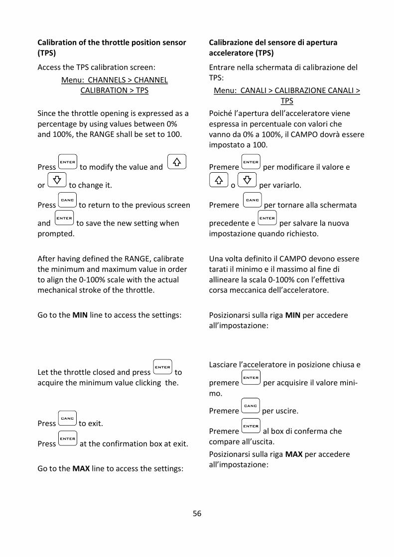
56
Calibration of the throttle position sensor (TPS)
Access the TPS calibration screen:
Menu: CHANNELS > CHANNEL CALIBRATION > TPS
Calibrazione del sensore di apertura acceleratore (TPS)
Entrare nella schermata di calibrazione del TPS:
Menu: CANALI > CALIBRAZIONE CANALI > TPS
Since the throttle opening is expressed as a percentage by using values between 0% and 100%, the RANGE shall be set to 100.
Poiché l’apertura dell’acceleratore viene espressa in percentuale con valori che vanno da 0% a 100%, il CAMPO dovrà essere impostato a 100.
Press to modify the value and
or to change it.
Press to return to the previous screen
and to save the new setting when prompted.
Premere per modificare il valore e
o per variarlo.
Premere per tornare alla schermata
precedente e per salvare la nuova impostazione quando richiesto.
After having defined the RANGE, calibrate the minimum and maximum value in order to align the 0-100% scale with the actual mechanical stroke of the throttle.
Go to the MIN line to access the settings:
Una volta definito il CAMPO devono essere tarati il minimo e il massimo al fine di allineare la scala 0-100% con l’effettiva corsa meccanica dell’acceleratore.
Posizionarsi sulla riga MIN per accedere all’impostazione:
Let the throttle closed and press to acquire the minimum value clicking the.
Press to exit.
Press at the confirmation box at exit.
Go to the MAX line to access the settings:
Lasciare l’acceleratore in posizione chiusa e
premere per acquisire il valore mini-mo.
Premere per uscire.
Premere al box di conferma che compare all’uscita.
Posizionarsi sulla riga MAX per accedere all’impostazione:
57
Open the throttle completely and press
to acquire the minimum value click-ing the.
Press to exit.
Press at the confirmation box at exit.
Aprire completamente l’acceleratore e
premere per acquisire il valore massimo.
Premere per uscire.
Premere al box di conferma che compare all’uscita.
Note: the GRAB command automatically inserts the value measured in real time by the sensor.
If the sensor is currently not connected or can not reach the actual extreme
positions but you know in advance the point values of minimum and maximum, however you can put them through the
EDIT.
Nota: il comando RILEVA consente di inserire automaticamente il valore
rilevato in tempo reale dal sensore. Se il sensore non è al momento collegato o non può raggiungere le posizioni degli
estremi effettivi ma si conoscono a priori i valori in punti di
minimo e massimo, è comunque possibile inserirli attraverso il il comando
MODIFICA.
Calibration of linear potentiometers (e.g. Suspension Sensors)
Perform the following operations to calibrate the linear sensors.
Enter the suspension sensor calibration screen:
Calibrazione dei potenziometri lineari (es. Sensori Sospensione)
Eseguire le seguenti operazioni per calibrare i sensori lineari.
Entrare nella schermata di calibrazione del sensore sospensione:
1. Extend the sensor completely.
2. Use a gauge to measure the distance between the stroke limit Seeger and the dust cover.
1. Estendere totalmente il sensore.
2. Misurare con il calibro la distanza tra il Seeger di fine corsa ed il parapolvere.
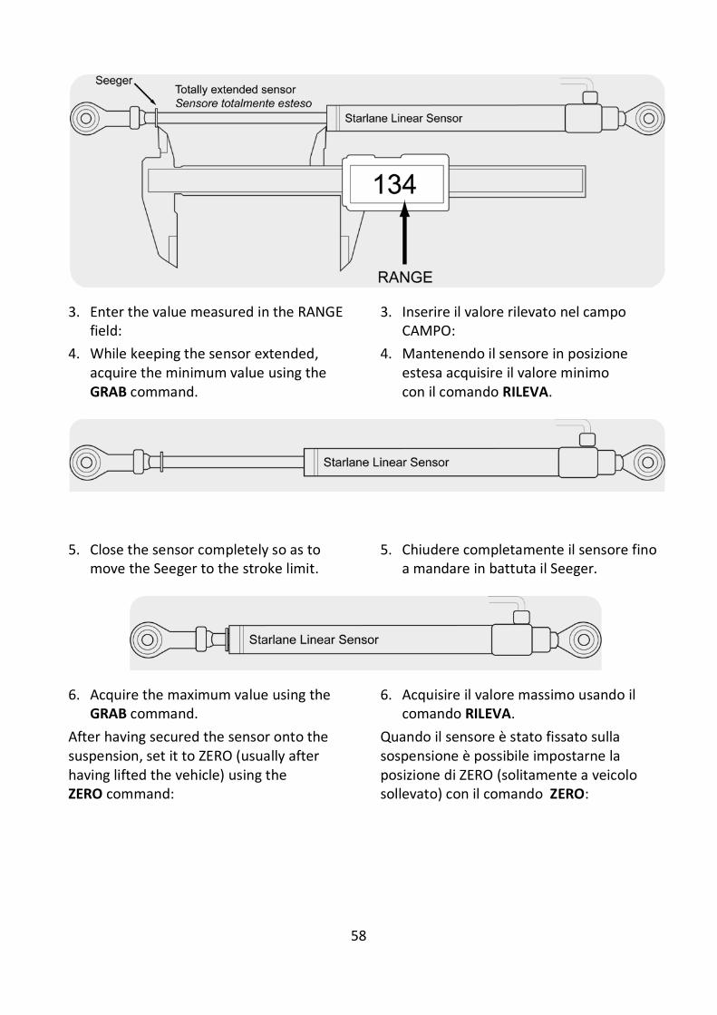
58
3. Enter the value measured in the RANGE field:
3. Inserire il valore rilevato nel campo CAMPO:
4. While keeping the sensor extended, acquire the minimum value using the GRAB command.
4. Mantenendo il sensore in posizione estesa acquisire il valore minimo con il comando RILEVA.
5. Close the sensor completely so as to move the Seeger to the stroke limit.
5. Chiudere completamente il sensore fino a mandare in battuta il Seeger.
6. Acquire the maximum value using the GRAB command.
6. Acquisire il valore massimo usando il comando RILEVA.
After having secured the sensor onto the suspension, set it to ZERO (usually after having lifted the vehicle) using the ZERO command:
Quando il sensore è stato fissato sulla sospensione è possibile impostarne la posizione di ZERO (solitamente a veicolo sollevato) con il comando ZERO:
59
Cleaning the surfaces
Use a soft cloth wetted with water to clean the surfaces of your DAVINCI-II. Using alco-hol or aggressive detergents might turn the transparent areas opaque.
Attention: do never aim pressure waterjet cleaners against the device!
Pulizia delle superfici
Per pulire le superfici del vostro DAVINCI-II usate un panno morbido bagnato con acqua, l’uso di alcool o deter-genti aggressivi può opacizzare le aree trasparenti.
Attenzione: non puntare mai pulitrici con getto d’acqua in pressione verso il
dispositivo!
Notes
Important for 2 Stroke Vehicle users
On all 2 stroke vehicles, due to the strong electromagnetic emissions caused by the ignition system, you must use spark plug caps of shielded type with 5000ohm internal resistor or spark plugs with internal resistor, often marked with the “R” letter in the code (e.g. NGK BR10EG instead of the normal B10EG).
Not using shielded cap or spark plug can caused the device hanging while the en-gine is running, requiring to unplug the power supply to restart the unit and the execution of the “FORMAT MEMORY” command in the MEMORY menu to re-store the correct status of the internal memory.
DAVINCI-II is not type-approved for road use.
Note
Importante per utenti di Veicoli 2 Tempi
Su tutti i veicoli 2 tempi, per via delle for-ti emissioni elettromagnetiche del siste-ma di accensione, è necessario utilizzare cappucci candela schermati con resisten-za interna da 5000 ohm oppure candele nella versione con resistenza interna, spesso contraddistinte dalla lettera “R” nella sigla (esempio NGK BR10EG anziché la normale B10EG).
Il mancato uso di pipetta o candela schermata può causare il bloccaggio del
dispositivo a motore acceso, richiedendo lo scollegamento dell’alimentazione per
riavviarlo e l’esecuzione del comando “FORMAT MEMORY” nel menù MEMORY
per ripristinare l’adeguato stato di funzionamento della memoria interna.
DAVINCI-II non è omologato per uso
stradale.
60
Warranty
DAVINCI-II is covered by a 24-month warranty for all manufacturing defects.
NOTE: For any update to the present
manual please visit the web site:
www.starlane.com
User Guide Version: DVII_001.02
Garanzia
DAVINCI-II è coperto da 24 mesi di garanzia sui difetti di fabbricazione.
NOTA: Eventuali aggiornamenti al presente manuale sono disponibili sul sito:
www.starlane.com
Versione Manuale: DVII_001.02
Starlane s.r.l.
Via Madonna delle Rose, 70
24061 - Albano S. Alessandro (BG)
Italia
e-mail: [email protected]
http://www.starlane.com