Embed Size (px)
DESCRIPTION
SCI-ARC_OFFICE WORK PORTFOLIO
Citation preview
DAVID ERVENPORTFOL IOS C I - A R C
2009 / VOLUME .01
MATERIALSMOVEMENT / CIRCULATION
PROCESS
SENSIBILITY
CONSTRUCTION
CASE STUDIES
ANALYSIS AND DEVELOPMENT
RELATIONSHIPS
DYNAMIC PERFORMANCE
PRAGMATIC PRINCIPLES
GENERATIVE APPROACH
COMMUNICATION
TECHNOLOGY
MAYA AUTODESK
METAMORPHOSES
MANIPULATED GEOMETRIES
EXERCISES
EXHIBITING PERFORMANCE
TECTONICS
ARTISAN / CRAFTSMAN
DEFORMATIONS
REPRESENTATION
VARIATIONS
WHAT’S IT MADE OF?
MODELING
LOGIC
PROVE IT!
NURBS VS. POLYGONS
FABRICATION
STRATEGIES
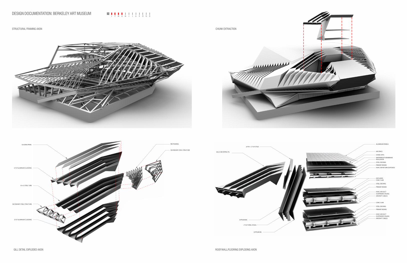
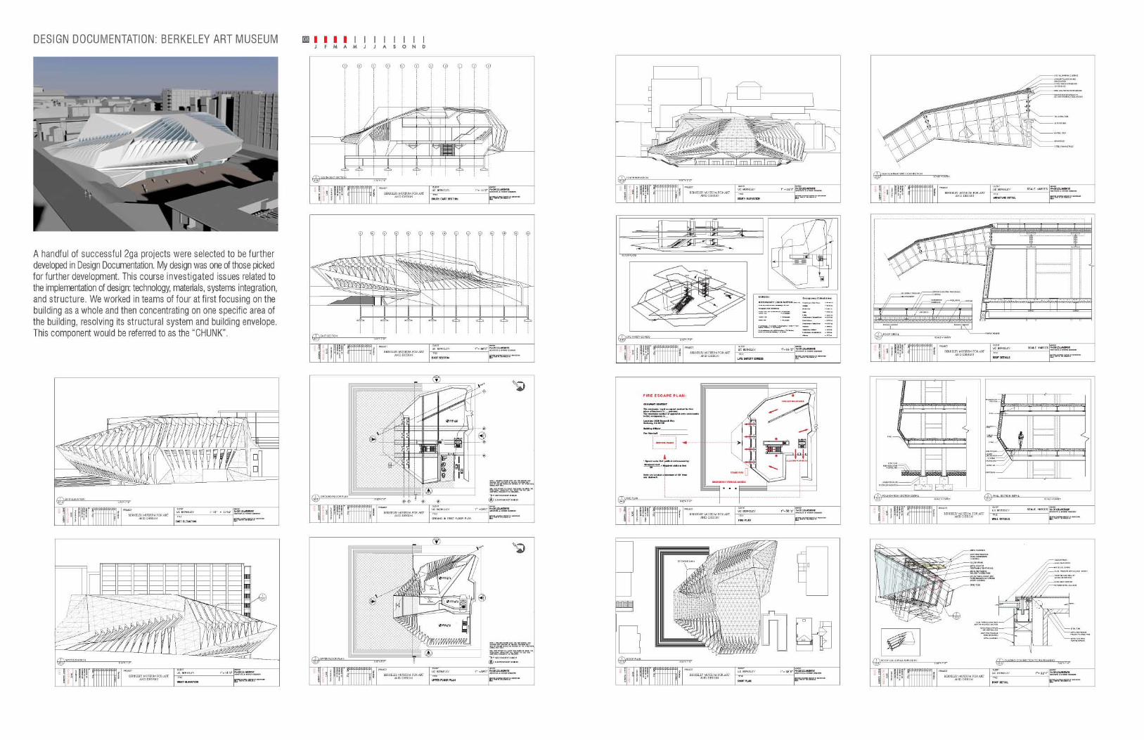
FINAL DESIGN: BERKELEY ART MUSEUM
PROCESS
07
PHYSICAL MODEL: FOAM COREINTERIOR ATRIUM
2GA STUDIO: DAVID ERVEN
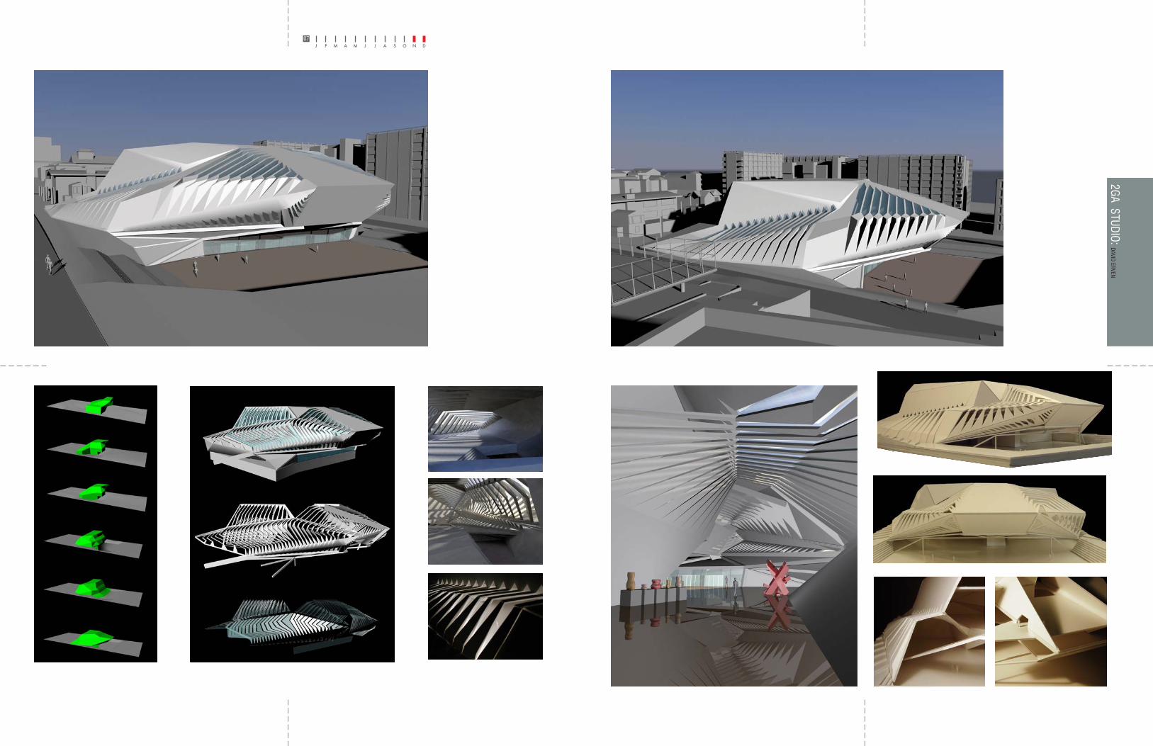
For the f ina l des ign the concept of strands to volume developed. The strands (gi l ls) of the mass are designed to d i ve rge f rom the exterior shell and into the interior and function as structural members supporting walls, floors, and ce i l i ngs , wh i l e also creating dynamic spaces u t i l i z ing the different roles of natural daylight. These strands var y in th ickness at certain moments to carry loads and to take on the behavior of strands dissolving perpendicular connections to the mass.
Deal ing w i t h the s i t e , t he west s ide o f t he bu i l d i ng i s embedded into the ear th while emerging out into a highly a r t i c u l a t e d c a n t i l e v e r , de f i n i ng t he entrance and plaza area.
57
BERKELEY MUSEUM FOR ART AND DESIGN
DR
AWIN
G TYP
E R.K
IM
AD
MIN
ISTR
ATIVE
ARCHITECTURAL
SHEET 0000 COVER0001 Table of Contents0002 A1.0 South Elevation0003 A1.2 West Elevation 0004 A1.3 North Elevation0005 A1.4 East Elevation0006 A2.0 Roof Plan0007 A2.1 Ground Floor Plan0008 A2.2 Upper Floor Plan0009 A3.0 South East Section0010 A3.1 East Section0011 A4.0 Fire Plan0012 A4.1 Life Safety Egress
STRUCTURAL
SHEET 0013 S1.0 Structural Framing Axon0014 S2.0 Chunk Extraction0015 S2.1 Roof Chunk Axon0016 S2.2 Gill Detail Exploded Axon0017 S2.3 Gill Ribs Axon0018 S2.4 Roof Detail0019 S2.5 Armature Detail0020 S3.0 Roof/Wall/Flooring Exploding Axon0021 S3.1 Roof Detail0022 S3.2 Wall Detail
SUSTAINABLITY
SHEET 0001 Ground Floor Plan Program Zoning0002 South East Program Zoning0003 Program Zoning0004 Material Research0005 Ventilation Systems0006 Environment0007 Site Weather Data
PANELLING SYSTEM
SHEET 0001 Panels Chunk0002 Panel Grid0003 Panels: Sizes & Dimensions0004 Panels: Cut Sheet
BERKELEY MUSEUM FOR ART AND DESIGN
DR
AWIN
G TYP
E
STR
UC
TUR
AL
SCALE VARIES
S3.21 FOUNDATION SECTION DETAIL
SCALE = VARIES
P.WO
OD
16” W BEAM
L PLATE BOLTED
WAFFLE SLAB
DROP CEILING
CONC. SLABFINISHED FLOOR
16.9075
2X8 METAL STUD
CONDUITCHANEL
8” TUBE
STEEL TOP PLATE
L SHAPEDCONC END PLATE
FOOTING FOUNDATION
UNSULATION PLATE
8”GRAVEL MIN.RIGID INSULATION
CONC. SLAB
HVAC
HVAC
S3.32 WALL SECTION DETAIL
SCALE = VARIES
BERKELEY MUSEUM FOR ART AND DESIGN
SCALE VARIES
DR
AWIN
G TYP
E P.WO
OD
STR
UC
TUR
AL
S3.11 ROOF DETAIL
SCALE = VARIES
SILICON GASKET
ADJUSTABLE STAND-OFFSUPPORT SLAB (STEEL THIN GAUGE)
CLADDING
INSULATION
PRIMARY MEMBER
DECKINGWATERPROOF MEMBRANE
(AIR SPACE)
GILLS: SEE DETAIL PG.
24” W + 2” X 8” STUD
STAND-OFFS
AIR SPACE
ALUMINUM PANELS
WATERPROOF MEMBRANEINSULATION
STEEL DECKING
STEEL DECKING
STEEL DECKING
PRIMARY BEAMS
HVHC AIR RETURN (EXPOSED)
HVHC AIR DUCTSUSPENDED CEILING
AIRCRAFT CABLES
CONC. SLABDIFFUSERS
PRIMARY BEAMS
HVHC AIR DUCTSUSPENDED CEILING
AIRCRAFT CABLESGYPSUM BD.
2” X 8” STEEL STUDS.
GYPSUM BD.
CONC. SLAB
PRIMARY BEAMS
S3.01 ROOF/WALL/FLOORING EXPLODING
SCALE = VARIES
BERKELEY MUSEUM FOR ART AND DESIGN
SCALE VARIES
DR
AWIN
G TYP
E D.E
RVE
N
STR
UC
TUR
AL
BERKELEY MUSEUM FOR ART AND DESIGN
SCALE VARIES
DR
AWIN
G TYP
E P.WO
OD
STR
UC
TUR
AL
S2.51 GLASS/ARMATURE CONNECTION
SCALE = VARIES
BERKELEY MUSEUM FOR ART AND DESIGN
32
DR
AWIN
G TYP
E R.K
IM
STR
UC
TUR
AL
S2.41 ROOF GILL DETAIL EXPLODED
1/32”= 1’-0” S2.32 GLAZING CONNECTION TO RIB FRAMING
1/32”= 1’-0”
EXTERIOR METAL CLADDING
METAL CLADDING
GLAZING PANEL
METAL ROD FOR RIB FRAMING REINFORCING
METAL RIB FRAMINGWELDED TO STEEL TUBE
STEEL TUBE
SKYLIGHT MULLION WELDEDTO RIB FRAMING CAP APPLIEDUNDER CLADDING
METAL RIB FRAMINGWELDED TO STEEL TUBE
STEEL TUBEMETAL TUBE SUPPORTSKYLIGHT MULLION
ALUM. PURIN & ALUM. SNAPBOTTOM W/ E.P.D.M. GASKETS
METAL ROD SPANFOR RIB FRAMING
#12 ST. STL. SCREW
ALUM. SNAP COVER
ALUM. PRESSURE BAR w/ E.P.D.M. GASKET
GLAZING PANEL
CONT. SILICONE SEALANT& FOAM BACKER ROD
ALUM. HEAD CLOSURE
STIFF FIRE PROOFING PANEL UNDERNEATH CLADDING
STIFF FIRE PROOFINGFOAM INSULATION
METAL CLADDING
S2.22
BERKELEY MUSEUM FOR ART AND DESIGN
32
DR
AWIN
G TYP
E D.E
RVE
N
STR
UC
TUR
AL
S2.31 ROOF GILL AXON
1/32”= 1’-0”
GILL STRUCTURE
GILL SKINNED
RIBBED FRAMING PERSPECTIVE
GLAZING PANEL
SECONDARY STEEL STRUCTURE
RIB FRAMING
3/16” ALUMINUM CLADDING
3/16” ALUMINUM CLADDING
SECONDARY STEEL STRUCTURE
10 x12 STEEL TUBE
S2.21 GILL DETAIL EXPLODED AXON
1/32”= 1’-0”
BERKELEY MUSEUM FOR ART AND DESIGN
SCALE VARIES
DR
AWIN
G TYP
E D. E
RVE
N
STR
UC
TUR
AL
S2.11 ROOF/WALL/FLOOR SECTION
1/16”= 1’-0”
BERKELEY MUSEUM FOR ART AND DESIGN
VARIES
DR
AWIN
G TYP
E D. E
RVE
N
STR
UC
TUR
AL
S2.01 CHUNK EXTRACTION
1/64”= 1’-0”
BERKELEY MUSEUM FOR ART AND DESIGN
64
DR
AWIN
G TYP
E D. E
RVE
N
STR
UC
TUR
AL
S1.01 STRUCTURAL FRAMING
1/64”= 1’-0”
BERKELEY MUSEUM FOR ART AND DESIGN
64
DR
AWIN
G TYP
E D. E
RVE
N
STR
UC
TUR
AL
TABLE OF CONTENTS
BERKELEY MUSEUM FOR ART AND DESIGN
DR
AWIN
G TYP
E R.K
IM
AD
MIN
ISTR
ATIVE
ARCHITECTURAL
SHEET 0000 COVER0001 Table of Contents0002 A1.0 South Elevation0003 A1.2 West Elevation 0004 A1.3 North Elevation0005 A1.4 East Elevation0006 A2.0 Roof Plan0007 A2.1 Ground Floor Plan0008 A2.2 Upper Floor Plan0009 A3.0 South East Section0010 A3.1 East Section0011 A4.0 Fire Plan0012 A4.1 Life Safety Egress
STRUCTURAL
SHEET 0013 S1.0 Structural Framing Axon0014 S2.0 Chunk Extraction0015 S2.1 Roof Chunk Axon0016 S2.2 Gill Detail Exploded Axon0017 S2.3 Roof Gill Axon0018 S2.4 Roof Detail0019 S2.5 Armature Detail0020 S3.0 Roof/Wall/Flooring Explod-ing Axon0021 S3.1 Roof Detail0022 S3.2 Wall Detail
SUSTAINABLITY
SHEET 0001 Ground Floor Plan Program Zoning0002 South East Program Zoning0003 Program Zoning0004 Material Research0005 Ventilation Systems0006 Environment0007 Site Weather Data
PANELLING SYSTEM
SHEET 0001 Panels Chunk0002 Panel Grid0003 Panels: Sizes & Dimensions0004 Panels: Cut Sheet
BERKELEY MUSEUM FOR ART AND DESIGN
DR
AWIN
G TYP
E
STR
UC
TUR
AL
SCALE VARIES
S3.21 FOUNDATION SECTION DETAIL
SCALE = VARIES
P.WO
OD
16” W BEAM
L PLATE BOLTED
WAFFLE SLAB
DROP CEILING
CONC. SLABFINISHED FLOOR
16.9075
2X8 METAL STUD
CONDUITCHANEL
8” TUBE
STEEL TOP PLATE
L SHAPEDCONC END PLATE
FOOTING FOUNDATION
UNSULATION PLATE
8”GRAVEL MIN.RIGID INSULATION
CONC. SLAB
HVAC
HVAC
S3.32 WALL SECTION DETAIL
SCALE = VARIES
BERKELEY MUSEUM FOR ART AND DESIGN
SCALE VARIES
DR
AWIN
G TYP
E P.WO
OD
STR
UC
TUR
AL
S3.11 ROOF DETAIL
SCALE = VARIES
SILICON GASKET
ADJUSTABLE STAND-OFFSUPPORT SLAB (STEEL THIN GAUGE)
CLADDING
INSULATION
PRIMARY MEMBER
DECKINGWATERPROOF MEMBRANE
(AIR SPACE)
GILLS: SEE DETAIL PG.
24” W + 2” X 8” STUD
STAND-OFFS
AIR SPACE
ALUMINUM PANELS
WATERPROOF MEMBRANEINSULATION
STEEL DECKING
STEEL DECKING
STEEL DECKING
PRIMARY BEAMS
HVHC AIR RETURN (EXPOSED)
HVHC AIR DUCTSUSPENDED CEILING
AIRCRAFT CABLES
CONC. SLABDIFFUSERS
PRIMARY BEAM
HVHC AIR DUCTSUSPENDED CEILING
AIRCRAFT CABLESGYPSUM BD.
2” X 8” STEEL STUDS.
GYPSUM BD.
CONC. SLAB
PRIMARY BEAM
S3.01 ROOF/WALL/FLOORING EXPLODING
SCALE = VARIES
BERKELEY MUSEUM FOR ART AND DESIGN
SCALE VARIES
DR
AWIN
G TYP
E D.E
RVE
N
STR
UC
TUR
AL
BERKELEY MUSEUM FOR ART AND DESIGN
SCALE VARIES
DR
AWIN
G TYP
E P.WO
OD
STR
UC
TUR
AL
S2.51 GLASS/ARMATURE CONNECTION
SCALE = VARIES
BERKELEY MUSEUM FOR ART AND DESIGN
32
DR
AWIN
G TYP
E R.K
IM
STR
UC
TUR
AL
S2.41 ROOF GILL DETAIL EXPLODED
1/32”= 1’-0” S2.32 GLAZING CONNECTION TO RIB FRAMING
1/32”= 1’-0”
EXTERIOR METAL CLADDING
METAL CLADDING
GLAZING PANEL
METAL ROD FOR RIB FRAMING REINFORCING
METAL RIB FRAMINGWELDED TO STEEL TUBE
STEEL TUBE
SKYLIGHT MULLION WELDEDTO RIB FRAMING CAP APPLIEDUNDER CLADDING
METAL RIB FRAMINGWELDED TO STEEL TUBE
STEEL TUBEMETAL TUBE SUPPORTSKYLIGHT MULLION
ALUM. PURIN & ALUM. SNAPBOTTOM W/ E.P.D.M. GASKETS
METAL ROD SPANFOR RIB FRAMING
#12 ST. STL. SCREW
ALUM. SNAP COVER
ALUM. PRESSURE BAR w/ E.P.D.M. GASKET
GLAZING PANEL
CONT. SILICONE SEALANT& FOAM BACKER ROD
ALUM. HEAD CLOSURE
STIFF FIRE PROOFING PANEL UNDERNEATH CLADDING
STIFF FIRE PROOFINGFOAM INSULATION
METAL CLADDING
S2.22
BERKELEY MUSEUM FOR ART AND DESIGN
32
DR
AWIN
G TYP
E D.E
RVE
N
STR
UC
TUR
AL
S2.31 ROOF GILL AXON
1/32”= 1’-0”
GILL STRUCTURE
GILL SKINNED
RIBBED FRAMING PERSPECTIVE
GLAZING PANEL
SECONDARY STEEL STRUCTURE
RIB FRAMING
3/16” ALUMINUM CLADDING
3/16” ALUMINUM CLADDING
SECONDARY STEEL STRUCTURE
10 x12 STEEL TUBE
S2.21 GILL DETAIL EXPLODED AXON
1/32”= 1’-0”
BERKELEY MUSEUM FOR ART AND DESIGN
SCALE VARIES
DR
AWIN
G TYP
E D. E
RVE
N
STR
UC
TUR
AL
S2.11 ROOF/WALL/FLOOR SECTION
1/16”= 1’-0”
BERKELEY MUSEUM FOR ART AND DESIGN
VARIES
DR
AWIN
G TYP
E D. E
RVE
N
STR
UC
TUR
AL
S2.01 CHUNK EXTRACTION
1/64”= 1’-0”
BERKELEY MUSEUM FOR ART AND DESIGN
64
DR
AWIN
G TYP
E D. E
RVE
N
STR
UC
TUR
AL
S1.01 STRUCTURAL FRAMING
1/64”= 1’-0”
BERKELEY MUSEUM FOR ART AND DESIGN
64
DR
AWIN
G TYP
E D. E
RVE
N
STR
UC
TUR
AL
TABLE OF CONTENTS
08DESIGN DOCUMENTATION: BERKELEY ART MUSEUM COR-
STRUCTURAL FRAMING AXON
ROOF/WALL/FLOORING EXPLODING AXONGILL DETAIL EXPLODED AXON
CHUNK EXTRACTION
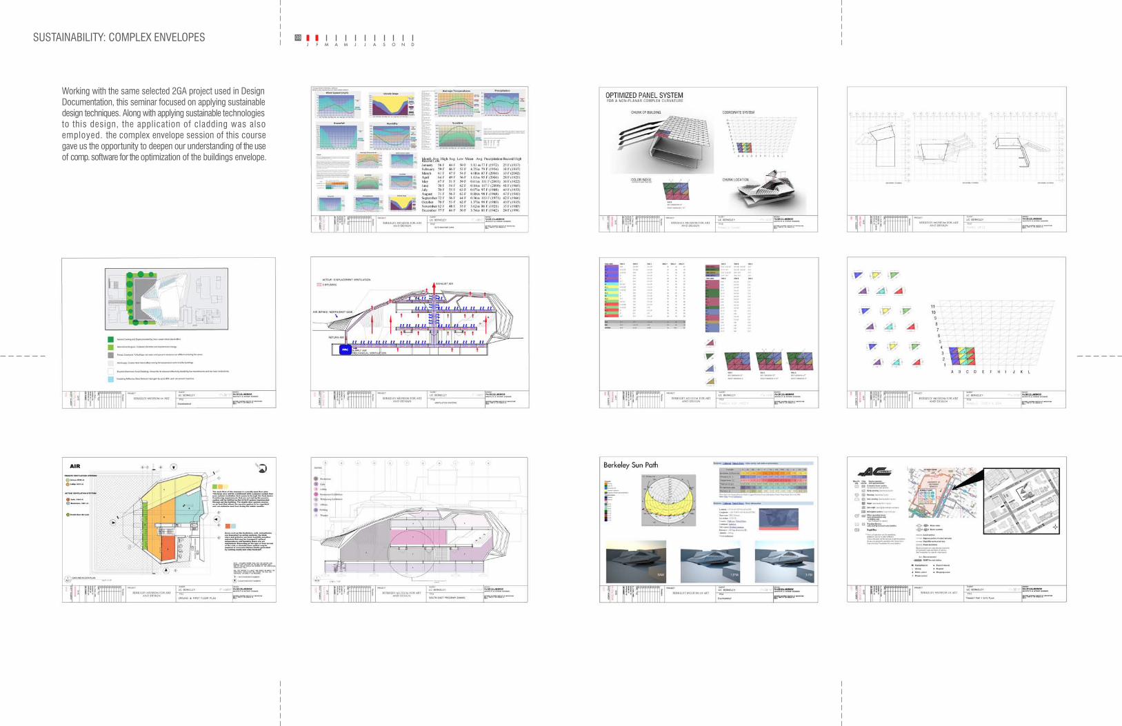
Working with the same selected 2GA project used in Design Documentation, this seminar focused on applying sustainable design techniques. Along with applying sustainable technologies to this design, the application of cladding was also employed. the complex envelope session of this course gave us the opportunity to deepen our understanding of the use of comp. software for the optimization of the buildings envelope.
SUSTAINABILITY: COMPLEX ENVELOPESRIDOR 08
OBSERVATION:
SITE:
SYSTEMS OF EXPERIMENTATION: POTENTIAL HOT AND COOL ZONES
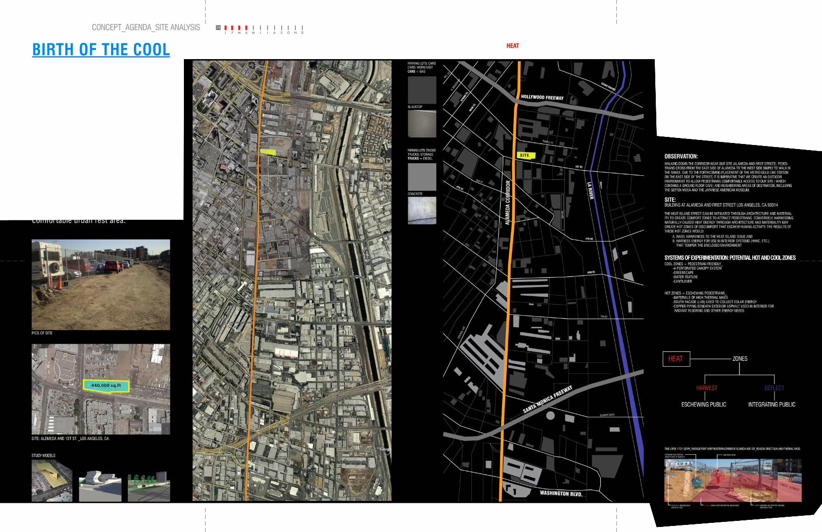
WALKING DOWN THE CORRIDOR NEAR OUR SITE (ALAMEDA AND FIRST STREET), PEDES-TRIANS CROSS FROM THE EAST SIDE OF ALAMEDA TO THE WEST SIDE SIMPLY TO WALK IN THE SHADE. DUE TO THE FORTHCOMING PLACEMENT OF THE METRO GOLD LINE STATION ON THE EAST SIDE OF THE STREET, IT IS IMPERATIVE THAT WE CREATE AN OUTDOOR ENVIRONMENT TO ALLOW PEDESTRIANS COMFORTABLE ACCESS TO OUR SITE ( WHICH CONTAINS A GROUND FLOOR CAFE) AND NEIGHBORING AREAS OF DESTINATION, INCLUDING THE GEFFEN MOCA AND THE JAPANESE AMERICAN MUSEUM.
BUILDING AT ALAMEDA AND FIRST STREET LOS ANGELES, CA 90014
THE HEAT ISLAND EFFECT CAN BE MITIGATED THROUGH ARCHITECTURE AND MATERIAL-ITY TO CREATE COMFORT ZONES TO ATTRACT PEDESTRIANS. CONVERSELY, HARNESSING NATURALLY-CAUSED HEAT ENERGY THROUGH ARCHITECTURE AND MATERIALITY MAY CREATE HOT ZONES OF DISCOMFORT THAT ESCHEW HUMAN ACTIVITY. THE RESULTS OF THESE HOT ZONES WOULD:
A. RAISE AWARENESS TO THE HEAT ISLAND ISSUE AND B. HARNESS ENERGY FOR USE IN INTERIOR SYSTEMS (HVAC, ETC.) THAT TEMPER THE ENCLOSED ENVIRONMENT
COOL ZONES = PEDESTRIAN FRIENDLY_ -A PERFORATED CANOPY SYSTEM -GREENSCAPE -WATER FEATURE -CANTILEVER
HOT ZONES = ESCHEWING PEDESTRIANS_ -MATERIALS OF HIGH THERMAL MASS -SOUTH FACADE (LAB) USED TO COLLECT SOLAR ENERGY -COPPER PIPING BENEATH EXTERIOR ASPHALT USED IN INTERIOR FOR RADIANT FLOORING AND OTHER ENERGY NEEDS
DATA WALL: ALAMEDA CORRIDOR
For this project we had to investigate the ecologies of the Alameda Corridor. This investigation engaged a series of parallel strategies: field research along the corridor & profound web-based investigations. Through this the discovering of information we were able to define economical, social, material, ecological, atmospheric, visual, and /or technological “deep structures” underlying the corridors ecology.
RODIRROC ADEMALA
SANTA MONICA FREEWAY
HOLLYWOOD FREEWAY
LA RIVER
7TH ST.
6TH ST.
4TH ST.
1ST ST.
CESAR CHAVEZ.
OLYMPIC BLVD.
CEN
TRAL
AVE
3RD ST.
TEMPLE ST.
CRA-I
CS
HILL ST.
N. BRO
ADWAY
SPRI
NG ST.
MAIN
ST.
4TH ST.
HEAT ZONES
INTEGRATING PUBLIC
HARVEST DEFLECT
ESCHEWING PUBLIC
TIME LAPSE: 1 TO 1.30 PM_VANTAGE POINT: NORTHEASTERN CORNER OF ALAMEDA AND 1ST_ REASON: DIRECT SUN, HIGH THERMAL MASS
FIRST STREET
CREWMAN TAKES REFUGEUNDER SHADE OF SIGNPOST
LONE PEDESTRIAN
ASPHALT: HIGHLY HEAT ABSORPTIVE AND RADIENT EARTH: ABSORBS HEAT INTO THE GROUND, SEMI-REFLECTIVE
CONCRETE: ABSORBS HEAT,REFLECTS LIGHT
MATERIALITY, THERMAL MASS, SUN AND SHADE
GENESIS MAPPING:
ASPHALT
SITE
CONCRETE/CEMENT
EARTH/UNDEVELOPED
HIGH
LOW
THESIS: HEAT DICTATES THE MOVEMENT AND LOCATION OF HUMAN BEINGS.
OBSERVATION:WALKING DOWN THE CORRIDOR NEAR OUR SITE (ALAMEDA AND FIRST STREET), PE-DESTRIANS CROSS FROM THE EAST SIDE OF ALAMEDA TO THE WEST SIMPLY TO WALK IN THE SHADE. DUE TO THE FORTHCOMING PLACEMENT OF THE METRO GOLD LINE STATION ON THE EAST SIDE OF THE STREET, IT IS IMPERATIVE THAT WE CREATE AN OUTDOOR ENVIRONMENT TO ALLOW PEDESTRIANS COMFORTABLE ACCESS TO OUR SITE (WHICH CONTAINS A GROUND FLOOR CAFE) AND NEIGHBORING AREAS OF DESTI-NATION, INCLUDING THE GEFFEN MOCA AND THE JAPANESE AMERICAN MUSEUM.
SITE:BUILDING AT ALAMEDA AND FIRST STREET, LOS ANGELES, CA 90014
THE HEAT ISLAND EFFECT CAN BE MITIGATED THROUGH ARCHITECTURE AND MATERI-ALITY TO CREATE COMFORT ZONES TO ATTRACT PEDESTRIANS. CONVERSELY, HARNESING NATURALLY-CAUSED HEAT ENERGY THROUGH ARCHITEC-TURE AND MATERIALITY MAY CREATE HOT ZONES OF DISCOMFORT THAT ESCHEW HUMAN ACTIVITY. THE RESULTS OF THESE HOT ZONES WOULD: A. RAISE AWARENESS TO THE HEAT ISLAND ISSUE AND B. HARNESS ENERGY FOR USE IN INTERIOR SYSTEMS (HVAC, ETC.) THAT TEMPER THE ENCLOSED ENVIRONMENT.
SYSTEMS OF EXPERIMENTATION: POTENTIAL HOT AND COOL ZONES
COOL ZONES = PEDESTRIAN FRIENDLY_ - A PERFORATED CANOPY SYSTEM - GREENSCAPE - WATER FEATURE - CANTILEVER
HOT ZONES = ESCHEWING PEDESTRIANS_ - MATERIALS OF HIGH THERMAL MASS - SOUTH FACADE (LAB) USED TO COLLECT SOLAR ENERGY - COPPER PIPING BENEATH EXTERIOR ASPHALT USED IN INTERIOR FOR RADIANT FLOORING AND OTHER ENERGY NEEDS
ENERGY: MATERIALITY = HEATPARKING LOTS: CARS/TRUCKS/PEOPLE
HEAT
HARVEST
ZONES
ESCHEWING PUBLIC INTEGRATING PUBLIC
DEFLECT
TIME LAPSE: 1 TO 1:30 PM_VANTAGE POINT: NORTHEASTERN CORNER OF ALAMEDA AND 1ST_REASON: DIRECT SUN, HIGH THERMAL MASS
CREWMAN TAKES REFUGEUNDER SHADE OF SIGNPOST
LONE PEDESTRIAN
CONCRETE ABSORBS HEATREFLECTS LIGHT
ASPHALT HIGHLY HEAT ABSORPTIVE AND RADIANT EARTH ABSORBS HEAT INTO THE GROUND, SEMI-REFLECTIVE
SITE
BIRTH OF THE COOLThe urban heat island (UHI) effect is an ever-growing phenomenon with great potential for causing serious environmental harm in our cities. It is imperative that swift action be taken to resolve/reduce this ongoing effect.
I propose the creation of a facility to house research labs committed to reducing the UHI effect while also providing an urban cool zone. These labs will locate and investigate fer tile ground, and different types of trees and vegetation in the heavily asphalted Alameda corridor; par ticularly in the downtown Los Angeles area. The public cool zone will bring awareness of the UHI effect to people in the downtown area, while also providing a comfor table urban rest area.
BIRTH OF THE COOL: CONCEPT_AGENDA_SITE ANALYSIS
ENERGY: MATERIALITY = HEAT
PARKING LOTS: CARS/TRUCKS/PEOPLE
ALAMEDA CORRIDOR
THE ABSENCE OF SOFSCAPE
ITERATION_1 ITERATION_2 ITERATION_3
08
For this project we had to investigate the ecologies of the Alameda Corridor. This investigation engaged a series of parallel strategies: field research along the corridor & profound web-based investigations. Through this, the discovering of information we were able to define economical, social, material, ecological, atmospheric, visual, and / or technological “deep structures” underlying the corridors ecology.
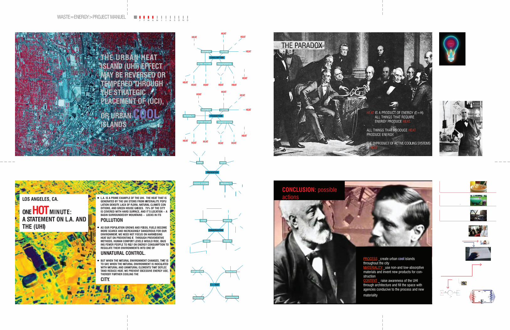
THE URBAN HEAT ISLAND (UHI) EFFECT MAY BE REVERSED OR TEMPERED THROUGH THE STRATEGIC PLACEMENT OF (UCI),
OR URBAN COOL ISLANDS
CHAPTER ONE
CONCLUSION: possible actions
PROCESS _create urban cool islands throughout the cityMATERIALITY _use non-and low-absorptive materials and invent new products for con-structionCONTENT _ raise awareness of the UHI through architecture and fill the space with agencies conducive to the process and new
materiality
L.A. IS A PRIME EXAMPLE OF THE UHI. THE HEAT THAT IS GENERATED BY THE UHI STEMS FROM MATERIALITY, POPU-LATION DENSITY, LACK OF FLORA, NATURAL CLIMATE CON-DITIONS, AND GREEN HOUSE GASSES. 75% OF THE CITY IS COVERED WITH HARD SURFACE, AND IT’S LOCATION -- A BASIN SURROUNDED BY MOUNTAINS -- LOCKS IN ITS
POLLUTION.
AS OUR POPULATION GROWS AND FOSSIL FUELS BECOME MORE SCARCE AND INCREASINGLY DANGEROUS FOR OUR ENVIRONMENT, WE NEED NOT FOCUS ON HARNESSING HEAT BUT ON PREVENTING IT. THROUGH PREVENTATIVE METHODS, HUMAN COMFORT LEVELS WOULD RISE, CAUS-ING FEWER PEOPLE TO RELY ON ENERGY CONSUMPTION TO REGULATE THEIR ENVIRONMENTS INTO ONE OF
UNNATURAL CONTROL. BUT WHEN THE NATURAL ENVIRONMENT CHANGES, THAT IS TO SAY, WHEN THE NATURAL ENVIRONMENT IS INOCULATED WITH NATURAL AND UNNATURAL ELEMENTS THAT DEFLEC-TAND REDUCE HEAT, WE PREVENT EXCESSIVE ENERGY USE, THEREBY FURTHER COOLING THE
CITY.E = HEAT
WATER
EQUIPMENT
TRANSPORTATION
EQUIPMENT
TRANSPORTATION
SUN
HUMAN
SHADE SOLAR STORAGE
MATERIALITY
MATERIALITYMATERIALITY
LIGHTING LIGHTING
ACTIVE SYSTEMS
GREEN ROOF REUSE
CONSUMPTION
PREVENTION
PRODUCTION
CONSERVATION
CONSERVATION
W.C. IRRIGATION
STORE
REUSE
HARNESS
REROUTE
PHOTOVOLTAIC CELLBATTERY
MATERIALABSORPTION
SOLAR
HUMAN
WATER PIPES
WATER PIPES
RADIANT FLOORING
MACHINE
AIR CIRCULATION
HEAT TRANSFERRESULTANT COLD WATER
RESULTANT HOT WATER
PREVENTION
SHADE
MATERIALITY
WATER
PASSIVE SYSTEMS
GREEN ROOF
TREES
ARCHITECTUREMISTERS
FOUNTAIN
POND
AIR CIRCULATION REFLECTION
DEFLECTION
TRANSMISSION
GRASS/EARTH
LIGHT COLOR
PLASTICS
GLASS/CONCRETE
EAVE CANTILEVERSTORE
PRODUCTION
HUMAN
CALORIES
HEAT
HEATHEAT
HEATHEAT
HEAT
HEAT
EQUIPMENT
MATERIALITY
TRANSPORTATION
LIGHTING
ACTIVE SYSTEMS
BUS/TRUCK/AUTO
TRAIN
BICYCLE WALKA/CHEATER
GASOLINE
COMPUTER, ETC.
METALS
METALS
L.E.D.
SUN
INCANDESCENT
ELECTRICITY
HEAT
ELECTRICITY
ELECTRICITY ELECTRICITY
ELECTRICITY
HEAT
ELECTRICITY
HEAT
GEOTHERMAL
CONSUMPTION
HUMAN
CALORIESHEAT
HEATHEAT
HEATHEAT
HEAT
HEAT
EQUIPMENT
TRANSPORTATION
LIGHTING
ACTIVE SYSTEMS
BUS/TRUCK/AUTO
TRAIN
BICYCLE WALKA/CHEATER
GASOLINE
COMPUTER, ETC. L.E.D.
SUN
INCANDESCENT
ELECTRICITY
HEAT
ELECTRICITY
ELECTRICITY ELECTRICITY
ELECTRICITY
HEAT
ELECTRICITY
HEAT
GEOTHERMAL
= HEAT
a spoon in a cup of hot soup becomes warmer because the heat from the soup is conducted along the spoon.
The Dutchtub is a wood-fired hot-tub that exploits convection to create heat and
bubbles.
Sunlight is a form of radia-tion that is radi-ated through space to our planet without the aid of fluids or solids.
ConductionConduction is the transfer of energy through matter from particle to particle. It is the transfer and distribution of heat energy from atom to atom within a substance. con-duction occurs as hot, rapidly moving or vibrating atoms and molecules interact with neighboring atoms and molecules, transferring some of their energy (heat) to these neighboring atoms. Conduction is most effective in solids-but it can happen in fluids.
ConvectionConvection is usually the dominant form of heat transfer in liquids and gases. This is a term used to characterize the combined effects of conduction and fluid flow. In convection, enthalpy transfer occurs by the movement of hot or cold portions of the fluid together with heat transfer by conduction. For example, when water is heated on a stove, hot water from the bottom of the pan rises, heating the water at the top of the pan. Two types of convection are commonly distinguished, free convection, in which gravity and buoyancy forces drive the fluid movement, and forced convec-tion, where a fan, stirrer, or other means is used to move the fluid.
RadiationRadiation is the only form of heat transfer that can occur in the absence of any form of medium; thus it is the only means of heat transfer through a volume of space that is essentially empty of matter. Radiation is Electromagnetic waves that directly transport ENERGY through space. Because there are no solids (like a huge spoon) touching the sun and our planet, conduction is not responsible for bringing heat to Earth. Since there are no fluids (like air and water) in space, convection is not responsible for transferring the heat. Thus, the suns radiation brings heat to our planet.
COMFORT OR DISCOMFORT?
thermal comfort is defined as the state of mind that expresses satisfaction with the surrounding environment. Maintaining thermal comfort for occupants of buildings or other enclosures is very prevelant in todays society ( especially in America). Thermal comfort is af-fected by heat conduction, convection, radiation and evaporative heat loss (Perspiration also called sweating). Thermal comfort is maintained when the heat generated by human metabolism is allowed to dissipate thus maintaining thermal equilibrium with the surroundings. Any heat gain or loss beyond this generates a sensation of thermal discomfort.
this discomfort is subjective to the individual and is recognised that the sensation of an individual feeling hot or cold is not just dependent on air temperature alone.
Factors determining thermal comfort include:
Air temperature • Mean radiant temperature • Air movement / velocity (wind chill factor) • Relative humidity (perspiration) • Insulative clothing • Activity levels• .
Without air conditioning, buildings must be built narrower or with light wells so that inner spaces receive sufficient outdoor air via natural ventilation. Air conditioning also allows buildings to be taller since wind speed increases significantly with altitude making natural ventilation impractical for very tall buildings.
The transfer of heat from an object, to another object with an equal or higher temperature, however, can happen only with the aid of a HEAT PUMP
A heat pump is a machine or device that moves heat from one location (the ‘source’) to another location (the ‘sink’ or ‘heat sink’). Heat pumps can be thought of as an heat engine (A heat engine is a physical or theoretical device that converts thermal energy to mechanical output)which is operating in reverse
HOW A HEAT PUMP WORKS:
HOW A HEAT ENGINE WORKS:
LegendCondenser coil (hot side heat exchanger) 1. Expansion valve (gas expands, cools and liquifies) 2. Evaporator coil (cold side heat exchanger) 3. Compressor 4. Red = Gas at high pressure and temperature 5. Pink = Gas at high pressure and reduced temperature 6. Blue = Liquid at low pressure and greatly reduced temperature 7. Light Blue = Gas at low pressure and warmer temperature8.
Heat pumps transfer heat from one place to another--providing both heating and cooling. A heat pump is an air conditioner that contains a valve that lets it switch between “air conditioner” and “heater.” When the valve is switched one way, the heat pump acts like an air conditioner, and when it is switched the other way it reverses the flow of Freon and acts like a heater
A heat sink (or heatsink) is an environment or object that absorbs and dissipates heat from another object using thermal contact (either direct or radiant). Heat sinks are used in a wide range of applications wherever efficient heat dissipa-tion is required; major examples include refrigeration, heat engines and cooling electronic devices.
General Electric engineers lit upon a solution: trap the heat-light through special ducts in the lighting fixtures, pipe it to outside rooms where it is needed most. They found that whole buildings could be heated inexpensively with nothing more than the lamps that light them.
EXAMPLE: an example of the new system to date is a two-year-old high school in Kimberly in north-ern Wisconsin, where temperatures have been known to drop as low as —31° in winter. The school was built with a minimum of outside windows and lots of fluorescent lights, all of which have built-in ducts that trap over 60% of their heat.* The ducts also collect the heat produced by the students’ bodies-which is surprisingly high. One average-size incumbent 15-year-old throws off more heat than a 100-watt bulb. Recovered and recirculated by fans, this heat from the lighting and the building’s occu-pants has proved more than enough to keep the building warm even when the outside thermometer reads 18°. The excess is transferred to heating coils in two 12,000-gal. water tanks. When the lights go out and the human dynamos go home at night and on weekends, the hot water from the tanks is circu-lated throughout the building to keep it warm. As a precautionary measure, the engineers also installed emergency electrical heaters, but Kimberly has almost never had to use them.
Heat by light recently got its biggest vote of confidence from two Chicago companies. The First National Bank of Chicago, which is about to start construction on a 60-story structure in the shape of a curved, inverted V, plans to use a similar system to heat the entire building. Last month, the John Hancock Insur-ance Co. announced that the 34 floors of office space in its planned 100-story, combination office-apart-ment building (TIME, April 2) will also be heated with light.
a light bulb puts out a lot of heat
LOS ANGELES, CA.
ONE
HOT
MINUTE: A STATEMENT ON L.A. AND THE (UHI)
BIRTH OF THE COOL: WASTE=ENERGY>PROJECT MANUEL 08
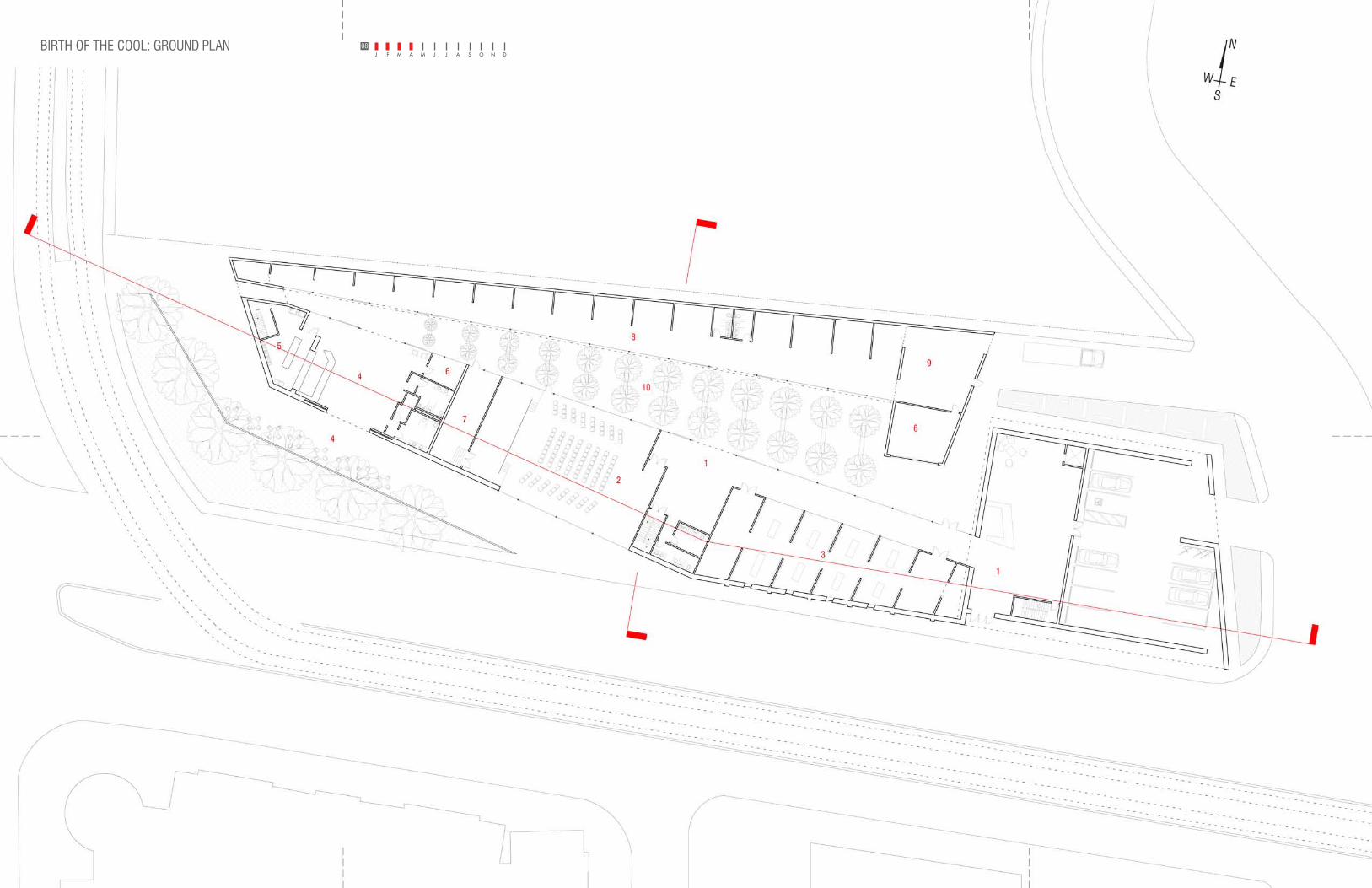
BIRTH OF THE COOL: GROUND PLAN 08
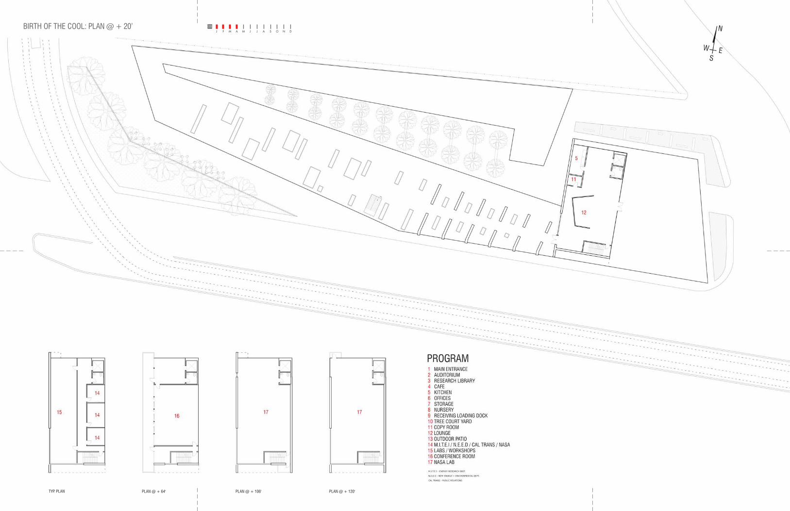
BIRTH OF THE COOL: PLAN @ + 20’ 08
14
14
14
1516
1717
12
11
5
1 MAIN ENTRANCE2 AUDITORIUM3 RESEARCH LIBRARY4 CAFE5 KITCHEN6 OFFICES7 STORAGE8 NURSERY9 RECEIVING LOADING DOCK10 TREE COURT YARD11 COPY ROOM12 LOUNGE13 OUTDOOR PATIO14 M.I.T.E.I / N.E.E.D / CAL TRANS / NASA15 LABS / WORKSHOPS16 CONFERENCE ROOM17 NASA LAB
PROGRAM
M.I.T.E.I - ENERGY RESEARCH INST.
N.E.E.D - NEW ENERGY + ENVIRONMENTAL DEPT.
CAL TRANS - PUBLIC RELATIONS
NASA- METEOROLOGICAL RESEARCHERS
TYP. PLAN
SCALE: 116"= 1'-0"
PLAN @ + 64' PLAN @ + 106' PLAN @ + 120'
DOWN
PLAN @ + 20’
SCALE 1
16 " = 1'-0"
N
SEW
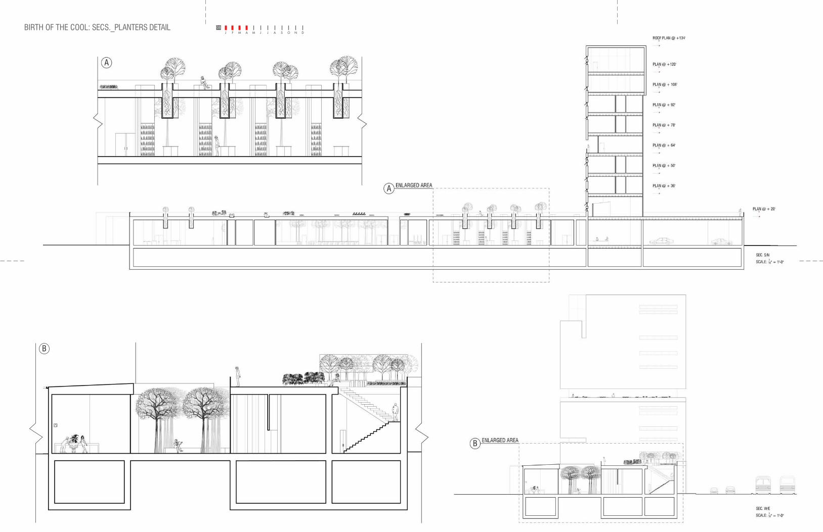
08BIRTH OF THE COOL: SECS._PLANTERS DETAIL
B
A
B
ENLARGED AREA
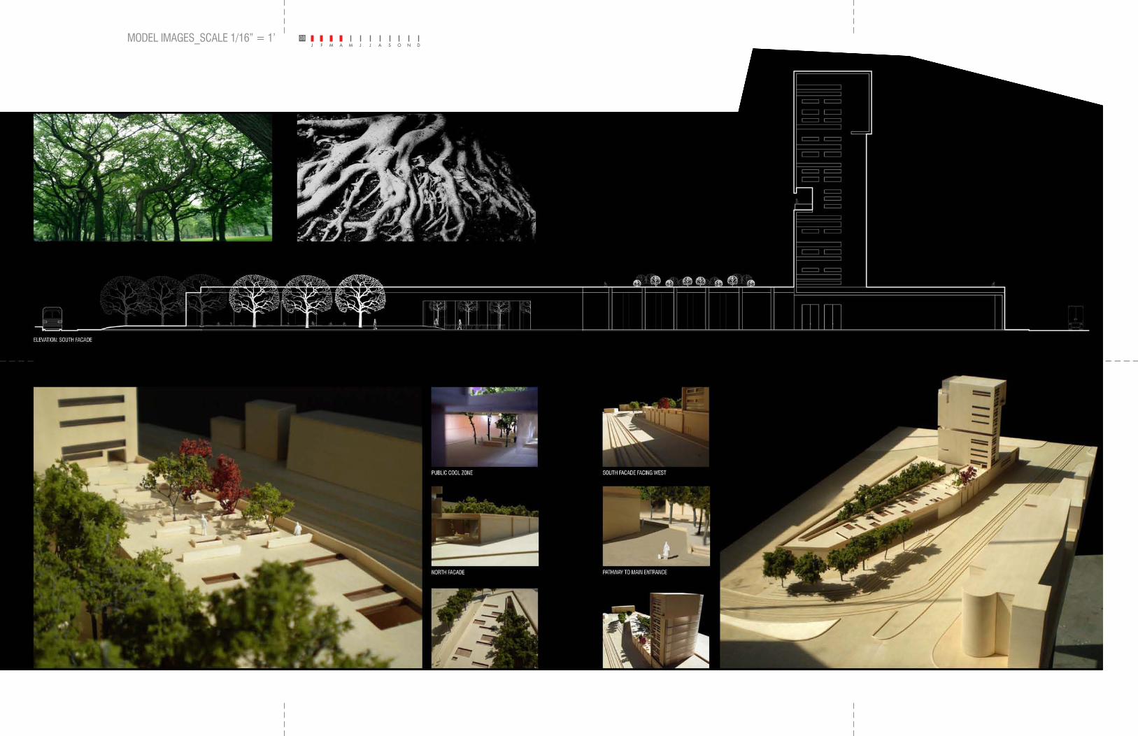
BIRTH OF THE COOL: MODEL IMAGES_SCALE 1/16” = 1’ 08
INTRODUCING SOFTSCAPE TO ALAMEDA
PUBLIC URBAN COOL ZONES:FOREST CANOPIES
ELEVATION: SOUTH FACADE
ROOF GARDEN ROOF GARDEN PERSPECTIVE W/ RESEARCH TOWER BIRDS EYE VIEW FACING EAST
LUGANO BASKETBALL SPORTS COMPLEX
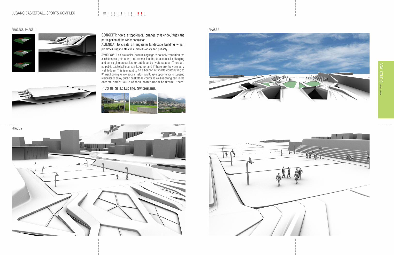
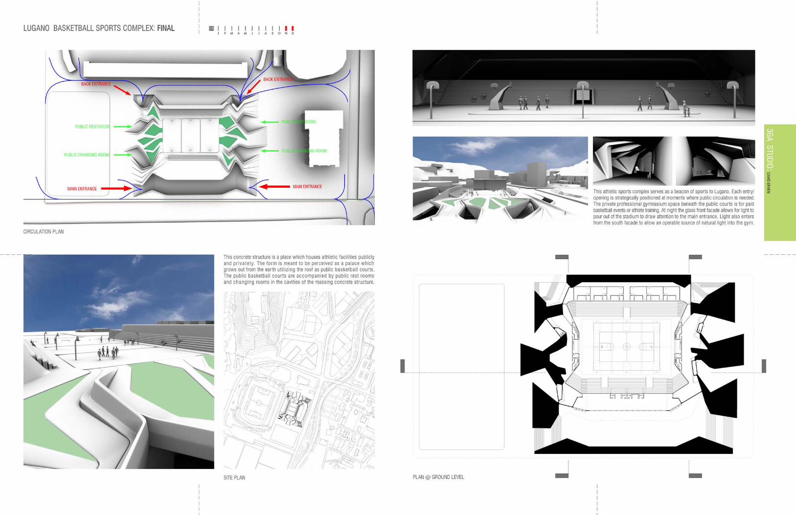
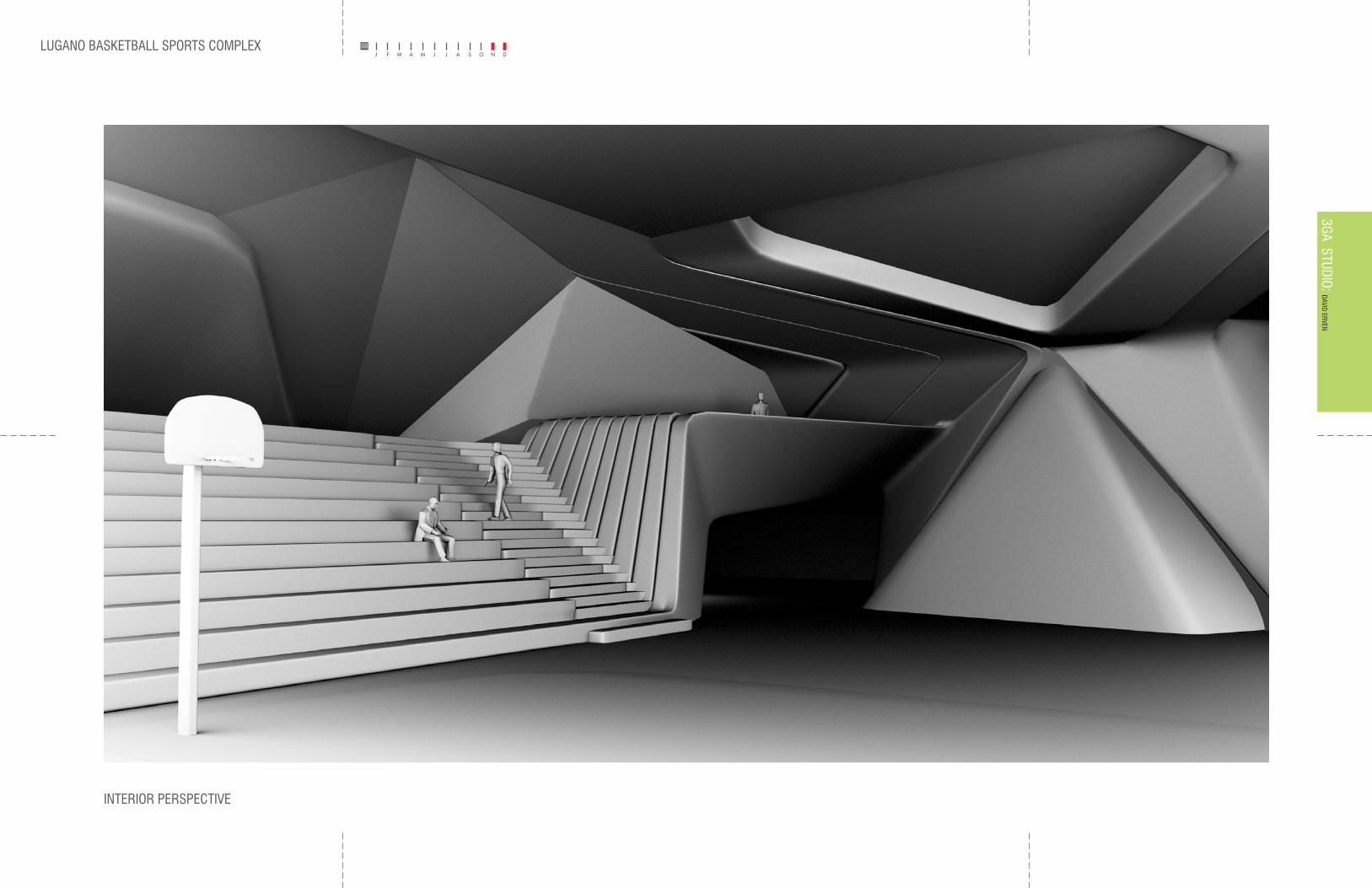
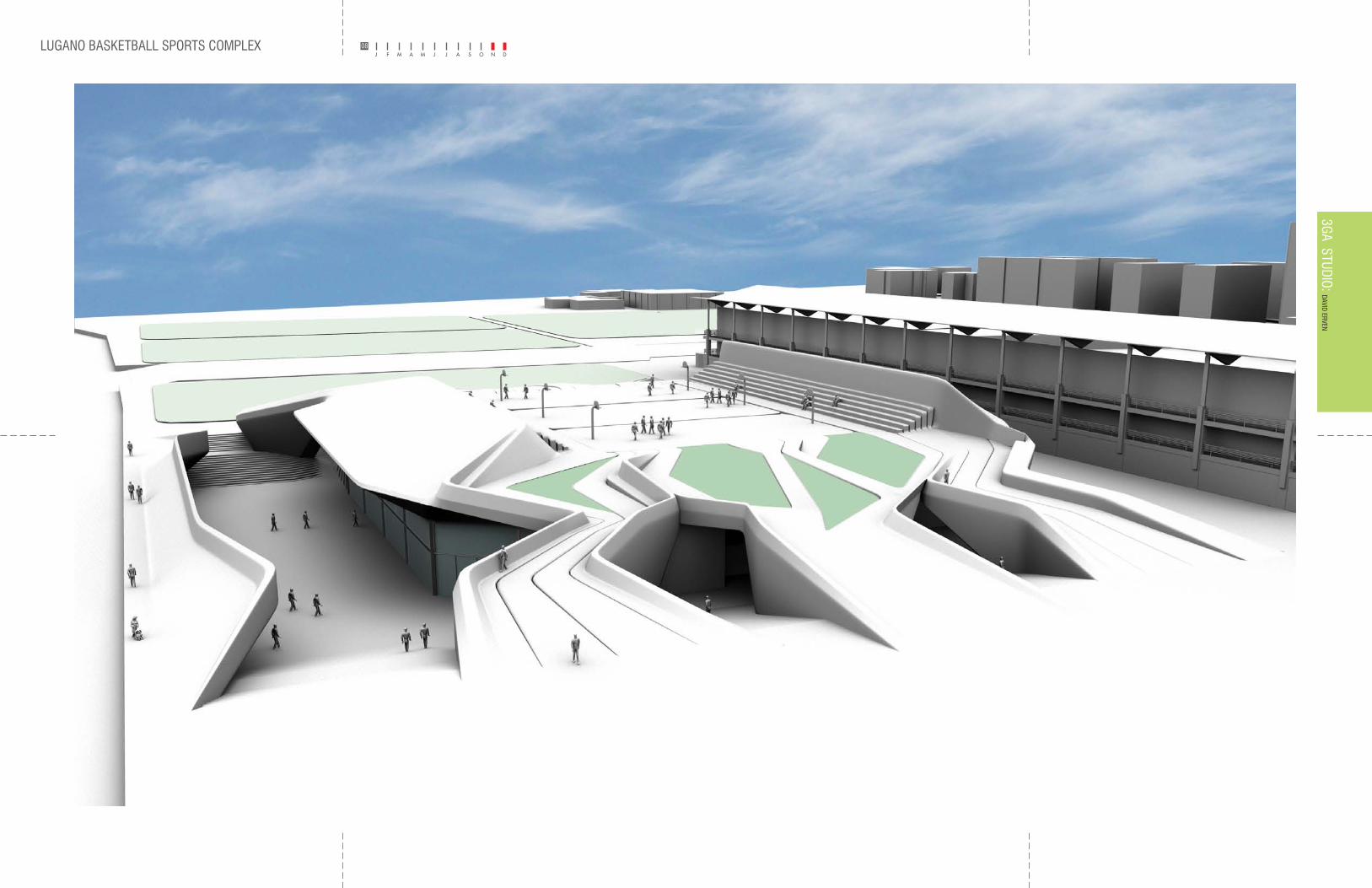
CONCEPT: force a topological change that encourages the participation of the wider population.AGENDA: to create an engaging landscape building which promotes Lugano athletics_professionaly and publicly.
3GA STUDIO: DAVID ERVEN
PROCESS: PHASE 1 PHASE 3
PHASE 2
SYNOPSIS: This is a radical pattern language to not only transition the earth to space, structure, and expression, but to also use its diverging and converging properties for public and private spaces. There are no public basketball courts in Lugano, and if there are they are very well hidden. This is meant to be a beacon of sports contributing to its neighboring active soccer fields, and to give opportunity for Lugano residents to enjoy public basketball courts as well as taking part in the enter tainment value of their professional basketball team.
PICS OF SITE: Lugano, Switzerland.
08
LUGANO BASKETBALL SPORTS COMPLEX
INTERIOR PERSPECTIVE
083GA STUDIO: DAVID ERVEN
LUGANO BASKETBALL SPORTS COMPLEX 083GA STUDIO: DAVID ERVEN
DETROIT PROJECT
DETROIT SITE MODEL
09
SCI-ARCAll School Exhibition
DAVID ERVENBETH SABBAHRAE SOLOMONANDREW ZAGO
EMPTY DENSITY:T he Detro it Project
Detroit RisingWhile Detroit’ s problems are well known and its physi ca l
in part, by hope. This optimis m is not groundless; while many feature s of Detroit’s urban declin e cont inue, a wave of redevelopmen t in the city, begun in the late nineties co ntinues and eve n grows . Detroiters watc h with opti-mis m as the tentative roots of new urba n growth take hold. A generation-old aver si on to investin g in the city is recedin g and Detroit’s economic v acuu m is sensed, by
-hoods across the city and dozen s of small-s ca le devel-opments by young artist s and do-it-yoursel f entrepre-neurs , Detroit is experie nc ing an unprecedented qua ntity and breadt h of new projects.
E m p t y D e n s i t yIn s pite of this growth, the city – in aggregat e – co ntinues to los e population. Mind- bogglingly large expanses of the city are feral with few resi dents - but an abundanc e of wildlife, unc hecke d vegetatio n and aba ndoned build-ings . The power of this urban tableau is undeniable. There is an uncann y atmosp here in Detroit - a sense of fullness and eve n lushness when, by any urban metric, it is empty. This empty density is not only a unique urba n sensib ility, it ca n s ugges t a tacti ca l tool for creating ur-banis m in the absence of buildings.
T he Detroit ProjectThe Detroit Project acknoledges that development , even in the mos t s u c c e s s f u l and active areas of the city, canno t expec t to achiev e its former built dens ity anytime s oon. Rathe r than reac t to this shortfal l with proposals of either suburban-graine d disper si on or wholesal e con-demnatio n and aba ndonment, the Detroit Project seek s
tactic s to render emptiness as opportunities for spatial and armospheric dens ity.
SF
SCIFI
3GB STUDIO: DAVID ERVEN, BETH SABBAH, RAE SOLOM
ON
it
3GB STUDIO: DAVID ERVEN, BETH SABBAH, RAE SOLOM
ON
DETROIT PROJECT 093GB STUDIO:
DAVID ERVEN, BETH SABBAH, RAE SOLOMON
Detroit RisingWhile Detroit’s problems are well known and it’s physical degradation well documented, it is also a city defined, in part, by hope. This optimism is not groundless; while many features of Detroit’s urban decline continue, a wave of redevelopment in the city, begun in the late nineties continues and even grows. Detroiters watch with optimism as the tentative roots of new urban growth take hold. A generation-old aversion to investing in the city is receding and Detroits economic vacuum is sensed, by some, as a field of opportunity. There are market-rate and subsidized infill housing elements in neighborhoods across the city and dozens of small-scale developments by young artists and do-it-yourself entrepreneurs, Detroit is experiencing an unprecedented quantity and breadth of new projects.
Empty DensityIn spite of this growth, the city-in aggregate-continues to lose population. Mind-bogglingly large expanses of the city are feral with few residents-but an abundance of wildlife, unchecked vegetation and abandoned buildings. The power of this urban tableau is undeniable. There is an uncanny atmosphere in Detroit-a sense of fullness and even lushness when, by any urban metric, it is empty. This empty density is not only a unique urban sensibility, it can suggest a tactical tool for creating urbanism in the absence of buildings. The Detroit ProjectThe Detroit Project acknowledges that development, even in the most successful and active areas of the city, cannot expect to achieve its former built density anytime soon. Rather than react to this shortfall with proposals of either suburban-grained dispersion or wholesale condemnation and abandonment, the Detroit Project seeks to defined programmatic, tectonic, ecological and figural tactics to render emptiness as opportunities for spatial and atmospheric density.
EMPTY DENSITY:The Detroit Project
ForestSuperblock
Solid geometry(Gothic Church)
Volumetric figuration with Volumetric figuration with creation of space with minimal(Fred Sandback)
Planar figuration (Piazza)
Volumetric figuration
OR
1. 2. 3. 4. 5.
Maximum physical PresenceMinimum Figuration
Minimum physical PresenceMaximum Figuration
with solid volumes with solid volumes curves [void] physical presence exuberant curves
Conceptual Diagrams
1. 2. 3. 4. 5.
A new aesthetic of erosion is a formal response to the disintegration of the city.A new aesthetic of erosion is a formal response to the disintegration of the city.A new aesthetic of erosion is a formal response to the disintegration of the city.A new aesthetic of erosion is a formal response to the disintegration of the city.
ForestSuperblock
Solid geometry(Gothic Church)
Volumetric figuration with Volumetric figuration with creation of space with minimal(Fred Sandback)
Planar figuration (Piazza)
Volumetric figuration
OR
1. 2. 3. 4. 5.
Maximum physical PresenceMinimum Figuration
Minimum physical PresenceMaximum Figuration
with solid volumes with solid volumes curves [void] physical presence exuberant curves
Conceptual Diagrams
1. 2. 3. 4. 5.
Project Diagrams
A new aesthetic of erosion is a formal response to the disintegration of the city.
DETROIT PROJECT 093GB STUDIO:
DAVID ERVEN, BETH SABBAH, RAE SOLOMON
DETROIT PROJECT 09
3GB STUDIO:
DAVID ERVEN, BETH SABBAH, RAE SOLOMON
DETROIT PROJECT 093GB STUDIO:
DAVID ERVEN, BETH SABBAH, RAE SOLOMON
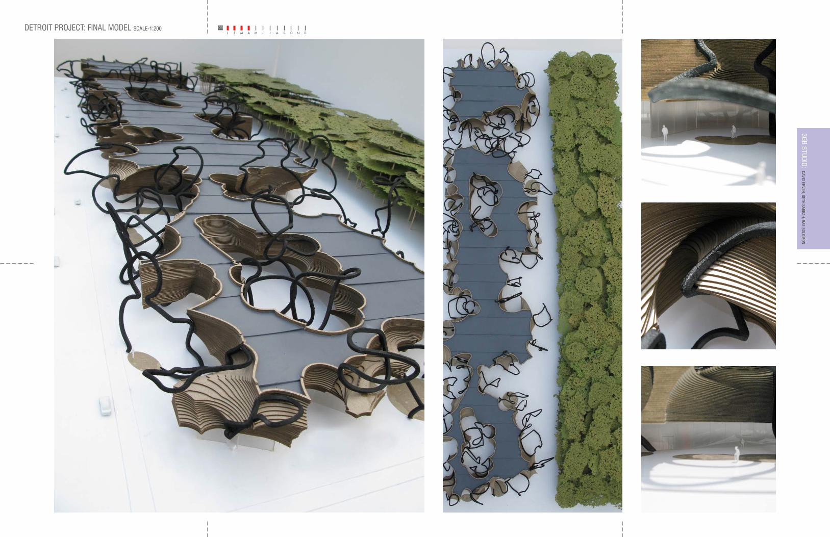
DETROIT PROJECT: FINAL MODEL SCALE-1:200 093GB STUDIO:
DAVID ERVEN, BETH SABBAH, RAE SOLOMON
16’32’
48’64’
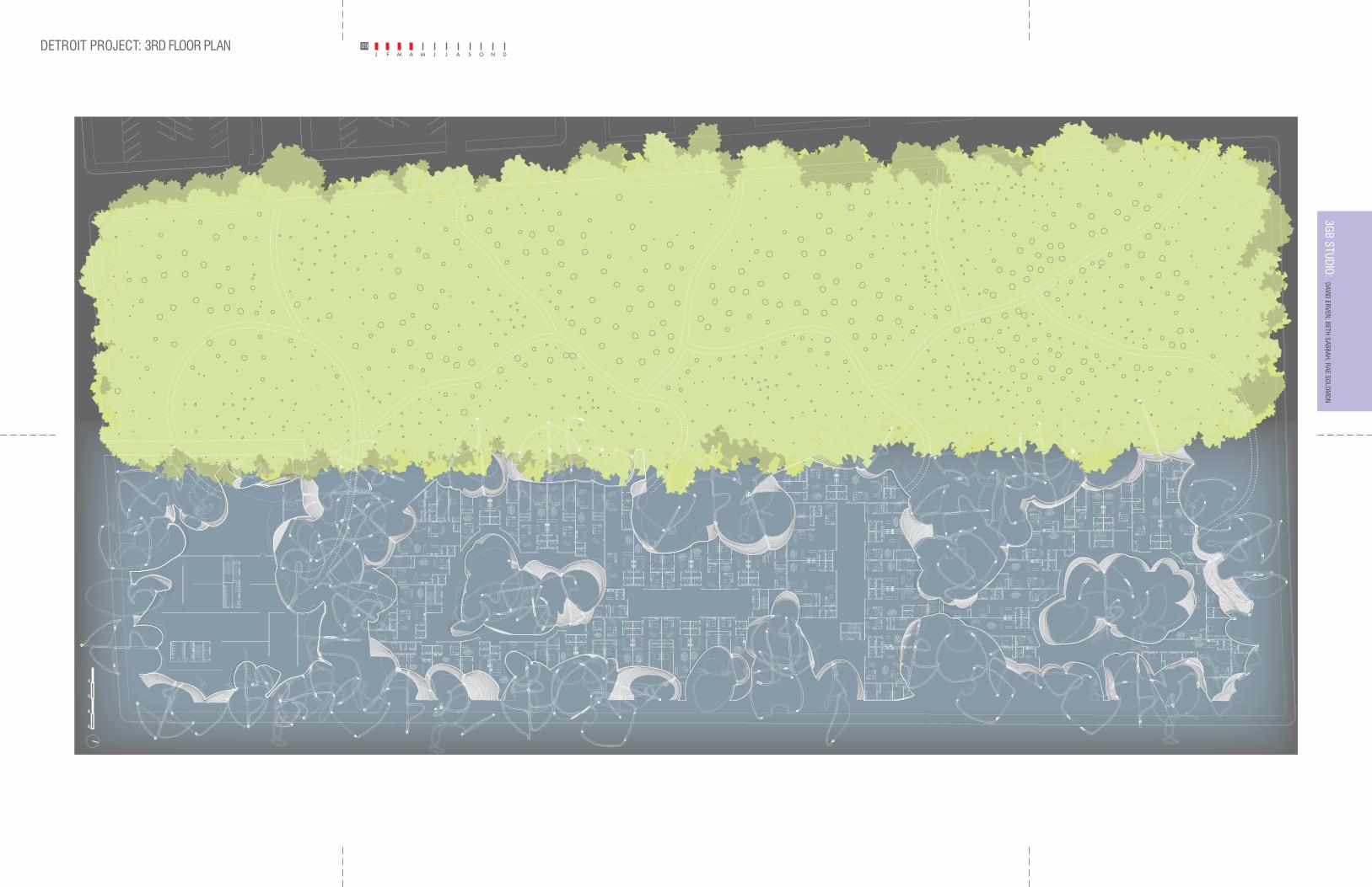
DETROIT PROJECT: 3RD FLOOR PLAN 093GB STUDIO:
DAVID ERVEN, BETH SABBAH, RAE SOLOMON
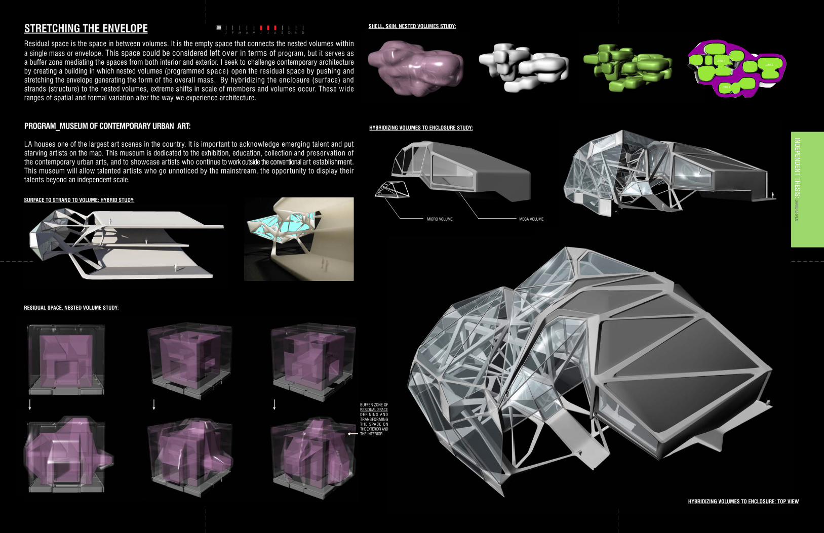
Residual space is the space in between volumes. It is the empty space that connects the nested volumes within a single mass or envelope. This space could be considered left over in terms of program, but it serves as a buffer zone mediating the spaces from both interior and exterior. I seek to challenge contemporary architecture by creating a building in which nested volumes (programmed space) open the residual space by pushing and stretching the envelope generating the form of the overall mass. By hybridizing the enclosure (sur face) and strands (structure) to the nested volumes, extreme shifts in scale of members and volumes occur. These wide ranges of spatial and formal variation alter the way we experience architecture.
STRETCHING THE ENVELOPE
STUDY MODELS:
BUFFER ZONE OF RESIDUAL SPACE DEFINING AND TRANSFORMING THE SPACE ON THE EXTERIOR AND THE INTERIOR.
SHELL, SKIN, CONTINUITY, RESIDUAL SPACE, NESTED VOLUMESEXAMPLES OF NESTED SPACES, OR • VOLUMES WITHIN VOLUMES.
• EXAMPLES OF A FOLDED CONTINUOUS • SURFACE.
RESIDUAL SPACE BETWEEN THE INTERIOR LINER AND THE EXTERIOR ARCHITECTURAL • SHELL CREATES SUBDIVISIONS OF NESTED VOLUMES. THIS RESIDUAL SPACE IS CAPABLE OF TRANSFORMING THE EXPERIENCE OF INTERIOR ARCHITECTURE WHILE ALSO INFORMING THE OVERALL GEOMETRY OF THE BUILDING
SHELL, SKIN, NESTED VOLUMES STUDY:
SURFACE TO STRAND TO VOLUME: HYBRID STUDY:
RESIDUAL SPACE, NESTED VOLUME STUDY:
HYBRIDIZING VOLUMES TO ENCLOSURE: TOP VIEW
DAVID ERVENINDEPENDENT THESIS:
PROGRAM_MUSEUM OF CONTEMPORARY URBAN ART:
LA houses one of the largest ar t scenes in the country. It is important to acknowledge emerging talent and put starving artists on the map. This museum is dedicated to the exhibition, education, collection and preservation of the contemporary urban arts, and to showcase artists who continue to work outside the conventional ar t establishment. This museum will allow talented ar tists who go unnoticed by the mainstream, the oppor tunity to display their talents beyond an independent scale.
09
STUDY MODELS:
BUFFER ZONE OF RESIDUAL SPACE DEFINING AND TRANSFORMING THE SPACE ON THE EXTERIOR AND THE INTERIOR.
SHELL, SKIN, CONTINUITY, RESIDUAL SPACE, NESTED VOLUMESEXAMPLES OF NESTED SPACES, OR • VOLUMES WITHIN VOLUMES.
• EXAMPLES OF A FOLDED CONTINUOUS • SURFACE.
RESIDUAL SPACE BETWEEN THE INTERIOR LINER AND THE EXTERIOR ARCHITECTURAL • SHELL CREATES SUBDIVISIONS OF NESTED VOLUMES. THIS RESIDUAL SPACE IS CAPABLE OF TRANSFORMING THE EXPERIENCE OF INTERIOR ARCHITECTURE WHILE ALSO INFORMING THE OVERALL GEOMETRY OF THE BUILDING
HYBRIDIZING VOLUMES TO ENCLOSURE STUDY:
MICRO VOLUME MEGA VOLUME
BUFFER ZONE OF RESIDUAL SPACE DEF IN ING AND TRANSFORMING THE SPACE ON THE EXTERIOR AND THE INTERIOR.
ZONE 1ZONE 2
ZONE 3
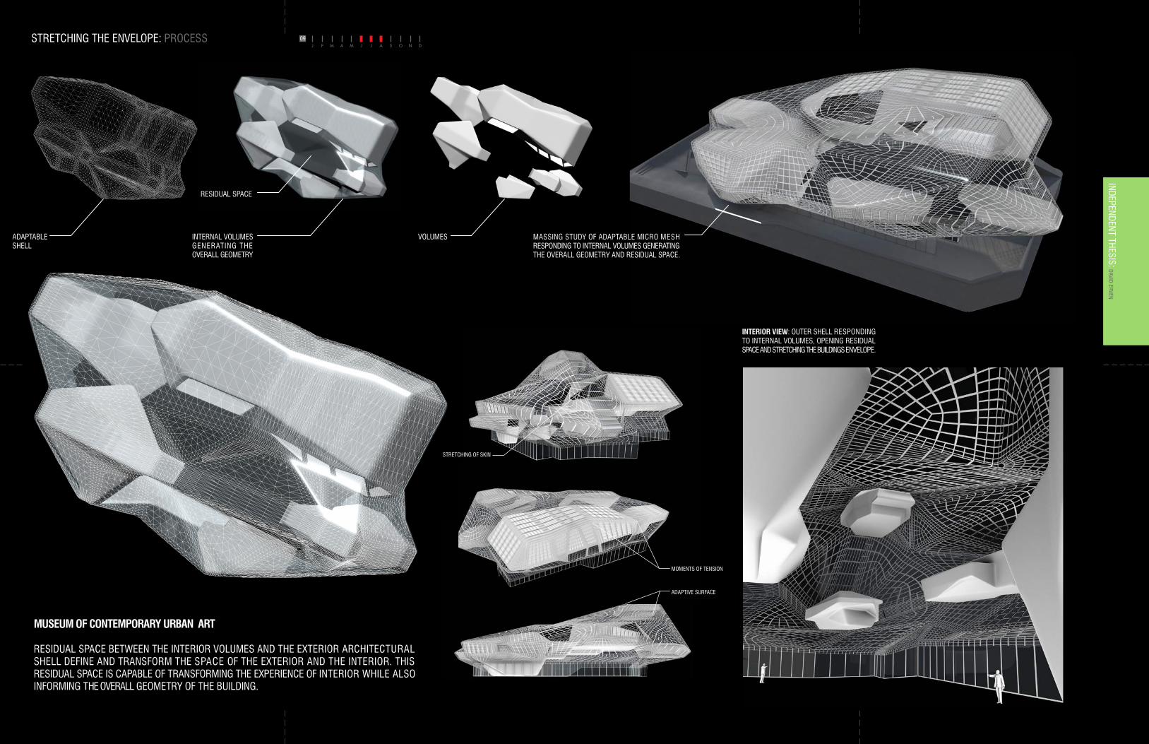
STRETCHING THE ENVELOPE: PROCESS 09DAVID ERVEN
INDEPENDENT THESIS:
STRETCHING OF SKIN
ADAPTABLE SHELL
INTERNAL VOLUMES GENERATING THE OVERALL GEOMETRY
RESIDUAL SPACE
VOLUMES
MOMENTS OF TENSION
ADAPTIVE SURFACE
MUSEUM OF CONTEMPORARY URBAN ART
RESIDUAL SPACE BETWEEN THE INTERIOR VOLUMES AND THE EXTERIOR ARCHITECTURAL SHELL DEFINE AND TRANSFORM THE SPACE OF THE EXTERIOR AND THE INTERIOR. THIS RESIDUAL SPACE IS CAPABLE OF TRANSFORMING THE EXPERIENCE OF INTERIOR WHILE ALSO INFORMING THE OVERALL GEOMETRY OF THE BUILDING.
INTERIOR VIEW: OUTER SHELL RESPONDING TO INTERNAL VOLUMES, OPENING RESIDUAL SPACE AND STRETCHING THE BUILDINGS ENVELOPE.
MASSING STUDY OF ADAPTABLE MICRO MESH RESPONDING TO INTERNAL VOLUMES GENERATING THE OVERALL GEOMETRY AND RESIDUAL SPACE.
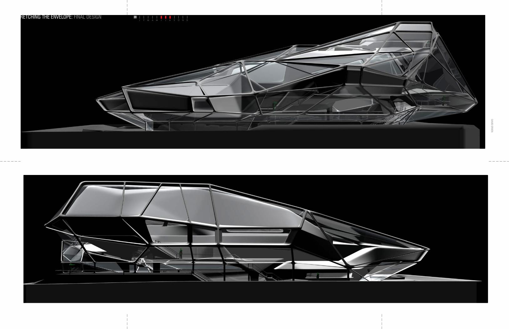
STRETCHING THE ENVELOPE: FINAL DESIGN
WEST ELEVATION
EAST ELEVATION
09DAVID ERVEN
INDEPENDENT THESIS:
STRETCHING THE ENVELOPE: AXO DAVID ERVEN
INDEPENDENT THESIS:09
PROGRAM VOLUMES
ADAPTABLE STRUCT.
ADAPTABLE SK IN
VOLUMES_ENVELOPE
VOLUMES_STRUCT_SKIN
FOUNDATION BASE
HYBRIDIZING SURFACE TOSTRUCTURE TO VOLUME
MASSING DETAIL
SHELL - TO - VECTOR - STRUCTURAL HYBRIDTHE STRUCTURE OF THIS BUILDING IS BASED ON A HYBRID OF SHELL BEHAVIOR, WHICH IS SURFACED BASED, AND SPACE FRAME BEHAVIOR, WHICH IS VECTOR-BASED. THE STRUCTURE ADAPTS FROM AN UNDER DIMENSIONED CONDITION BASED ON LOCAL GEOMETRICAL AND BENDING MOMENT CONDITIONS. THE SHELL BEHAVIOR TRANSFORMS INTO BENDING BEHAVIOR, RESULTING IN A SHIFT FROM SURFACE TO VECTOR MORPHOLOGY.
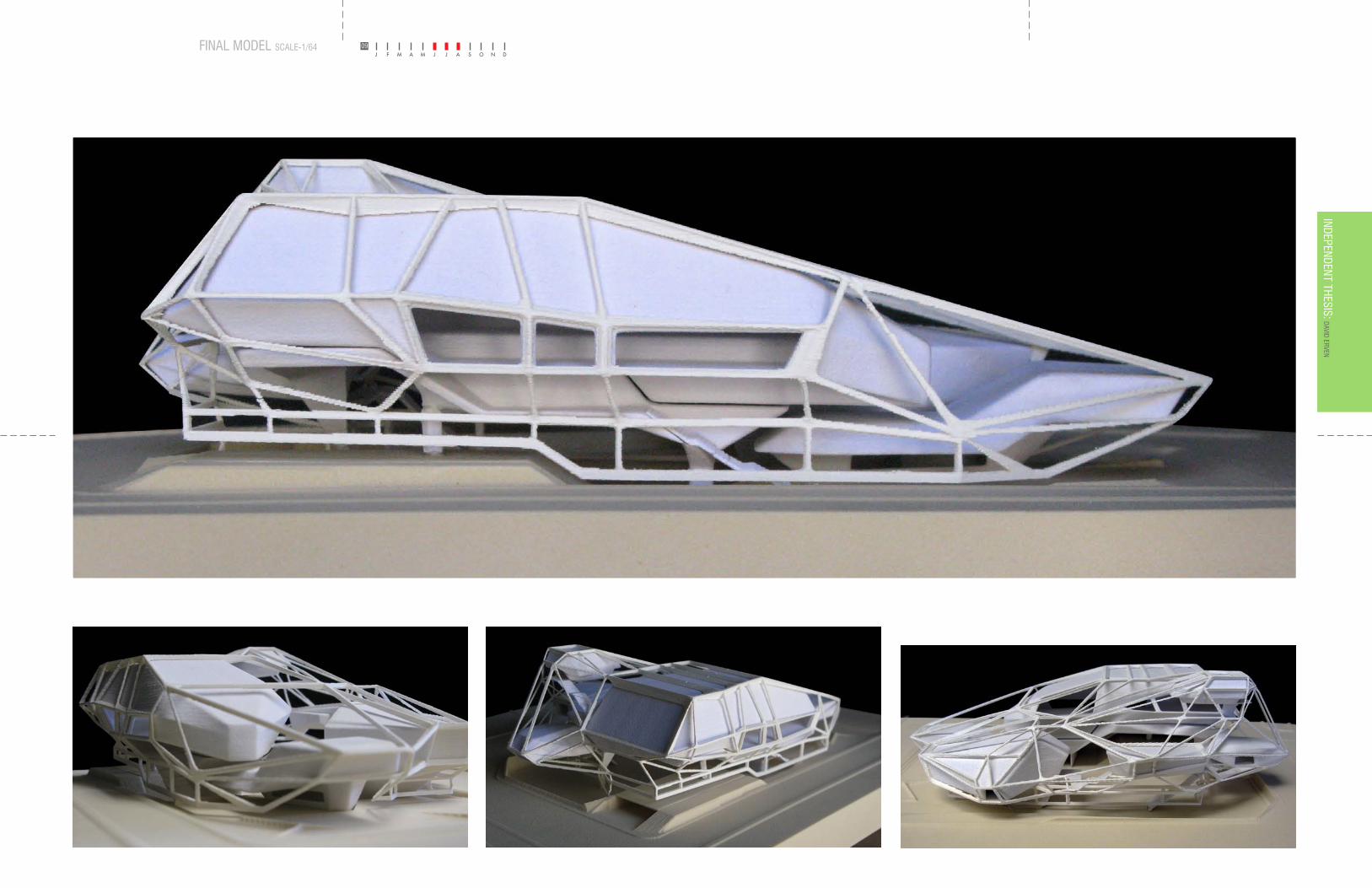
STRETCHING THE ENVELOPE: FINAL MODEL SCALE-1/64 09DAVID ERVEN
INDEPENDENT THESIS:
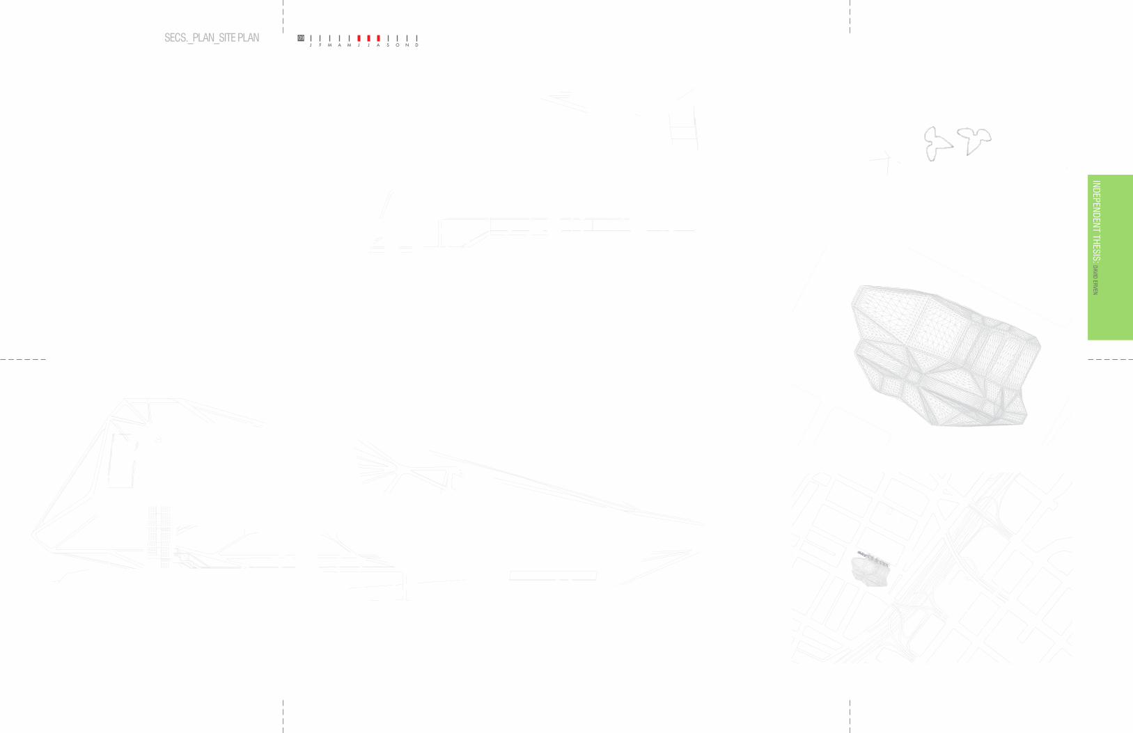
STRETCHING THE ENVELOPE: SECS._PLAN_SITE PLAN 09DAVID ERVEN
INDEPENDENT THESIS:
SCULPTURE GARDEN
FRONT ATRIUM
INFORMATION / CHECK IN
MAIN SPACE
TEMP. EXHIBITIONS
OFFICES STAFF ENTRANCEOFFICESOFFICES
GALLERY / CORRIDOR
DOW
N
UP
DOW
N
UP
UP
RAMP
RAMP
UNDERGROUND PARKING / DELIVERY DOCK
PLAN @ 4’-0”SCALE: 1/16” = 1’-0”
SEC. ASCALE: 1/16” = 1’-0”
SEC. BSCALE: 1/16” = 1’-0”
PLAN @ 4’-0”
ROOF PLAN
SITE PLAN_6TH STREET & BIXEL AVE.DOWNTOWN_LOS ANGELES, CA.
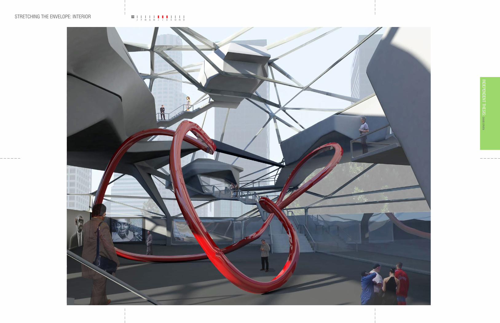
STRETCHING THE ENVELOPE: INTERIOR 09DAVID ERVEN
INDEPENDENT THESIS:
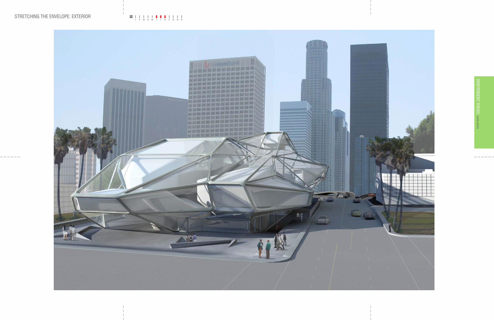
STRETCHING THE ENVELOPE: EXTERIOR 09DAVID ERVEN
INDEPENDENT THESIS:
SELECTED PROJECTS
DAVID ERVEN_SCI-ARC
LUGANO BASKETBALL SPORTS COMPLEX_2008
STRETCHING THE ENVELOPE: GRADUATE THESIS PROJECT_2009
BERKELEY ART MUSEUM_2007
BERKELEY ART MUSEUM: DESIGN DOCUMENTATION_2008
BERKELEY ART MUSEUM: SUSTAINABILITY_COMPLEX ENVELOPES_2008
DETROIT PROJECT: EMPTY DENSITY_2009
BIRTH OF THE COOL: PROJECT MANUEL_2008
BIRTH OF THE COOL_2008
DESIGNER: DAVID ERVEN
DESIGNER: DAVID ERVEN
DESIGNER: DAVID ERVEN
DESIGNER: DAVID ERVEN
DESIGNER: DAVID ERVEN
DESIGNERS: DAVID ERVEN, RAE SOLOMON, & BETH SABAH
STUDIO INSTRUCTOR: LUDOVICA MOLO
THESIS ADVISOR: TOM WISCOMBE
STUDIO INSTRUCTOR: TOM WISCOMBEDIGITAL MODELING AND RENDERS - MAYA 8.5 DIGITAL MODELING AND RENDERS - MAYA 2008
DIGITAL MODELING AND RENDERS - MAYA 2008_RHINO 4.0
DIGITAL MODELING AND RENDERS - MAYA 2008_RHINO 4.0
DIGITAL MODELING AND RENDERS - MAYA 8.5_RHINO 4.0
DIGITAL MODELING AND RENDERS - MAYA 8.5_RHINO 4.0
DIGITAL MODELING AND RENDERS - MAYA 2008_RHINO 4.0
DIGITAL MODELING AND RENDERS - MAYA 2008_RHINO 4.0
LAYOUTS AND RENDER MANIPULATIONS - IA CS & PHOTOSHOP CS LAYOUTS AND RENDER MANIPULATIONS - IA CS & PHOTOSHOP CS
LAYOUTS AND RENDER MANIPULATIONS - IA CS3_PHOTOSOP CS3_IN-DESIGN CS3
LAYOUTS AND RENDER MANIPULATIONS - IA CS3_PHOTOSOP CS3_IN-DESIGN CS3
LAYOUTS AND RENDER MANIPULATIONS - IA CS & PHOTOSHOP CS
LAYOUTS AND DIAGRAMS - IA CS & PHOTOSHOP CS
LAYOUTS AND DIAGRAMS - IA CS_PHOTOSHOP CS_IN-DESIGN CS
LAYOUTS AND DIAGRAMS - IA CS_PHOTOSHOP CS_IN-DESIGN CS
DRAWINGS - AUTOCAD 2007 DRAWINGS - AUTOCAD 2007
DRAWINGS - AUTOCAD 2007_RHINO 4.0
DRAWINGS - AUTOCAD 2007_RHINO 4.0
DRAWINGS - AUTOCAD 2007_RHINO 4.0
DRAWINGS - AUTOCAD 2007_RHINO 4.0
DRAWINGS - AUTOCAD 2007_RHINO 4.0
DRAWINGS - AUTOCAD 2007PHYSICAL MODEL - PLYWOOD, BASSWOOD & PLEX_SCALE: 1/16” = 1’-0”
ANALYSIS - IE
ANALYSIS - IE & RIGOROUS ON SITE OBSERVATION
ANALYSIS - IE & RIGOROUS ON SITE OBSERVATION
PHYSICAL MODEL - FOAM CORE_SCALE: 1/2”=1’-0” PHYSICAL MODEL - CHIP BOARD_SCALE: 1:200=1’-0”
PHYSICAL MODEL - CHIP BOARD, MDF, 3D-PRINTS, PLEX, POLYSTYRENE_SCALE: 1:200=1’-0”
PHYSICAL MODEL - FOAM MILL, 3D-PRINTS_SCALE: 1/64”=1’-0”
STUDIO INSTRUCTOR: TOM WISCOMBE & JOHN ENRIGHT
TEAM: DAVID ERVEN & DAVID OREGAN
TEAM: DAVID ERVEN, DAVID OREGAN, PETER WOOD, & RUTH KIM
STUDIO INSTRUCTOR: ILARIA MAZZOLENI & ROBERTO DAVOLIO
STUDIO INSTRUCTOR: ANDREW ZAGO
TEAM: DAVID ERVEN & ALISON SYKES
DESIGNER: DAVID ERVEN
TEAM: DAVID ERVEN, RAE SOLOMON, & BETH SABAH
STUDIO INSTRUCTOR: ILARIA MAZZOLENI
STUDIO INSTRUCTOR: ILARIA MAZZOLENI
W.B. Yeats wrote, “Education is not the filling of a pail, but the lighting of a fire”. It is hoped this por tfolio, in a very valid way, demonstrates what Yeats intended. My por tfolio represents the effect SCI-ARC has had on the growth and evolution of my skills, both technical and conceptual. Most impor tantly one can see in retrospect, how much the SCI-ARC experience has taught me to strive for a unique place in the field of architectural design rather than rely soley on what others have previously accomplished.
I have been for tunate to have instructors teach me to see things in many different ways. They have inspired me to be innovative by maintaining standards that push me to do my best work. I did not fully appreciate this experience until I looked back. As I assembled this por tfolio and had the oppor tunity to reflect on my personal growth as a designer, I have come to realize the value of what my teachers have impar ted to me.
Frustration and the tenacity to overcome challenges have been my par tners in learning to use advanced computer software to conver t my architectural visions into graphic form. This struggle, however, has taught me that what I thought was impossible can become reality, one step at a time.
My work has also taught me the pros and cons of team-work. It is no easy task to overcome communication barriers that inevitably come into play when working with different levels of competence. I have also become more confident in being a leader and knowing when it is time to step up to the plate.
Studying abroad in Europe served to greatly broaden my horizons. It is where I learned to appreciate the historical foundation of western architectural principles. I also know now there is no better way to launch yourself into the future than by understanding the past.
If there is a theme to my por tfolio and a conclusion to be drawn from a SCI-ARC education, it is that Yeats’ fire has been lit. I have been able to take the suppor t, instruction and guidance of many talented teachers and classmates and forge them in to a s ty le tha t wi l l no t compromise the integrity of my vision.
DAVID ERVEN

Abramson Teiger Architects: Associate July-Oct. 10’_Los Angeles, CA.
Gordon Kipping Architects: Model Maker spring 10’_ New York, NY.
Massey+Hoffman Architects: Intern summer 08’_Chicago, IL.
Callas+Shortridge Architects: Intern summer 07’_Los Angeles, CA.
Kanner Architects: Intern/Model Maker spring 06’_Santa Monica, CA.
D A V I D E R V E NO F F I C E W O R K S
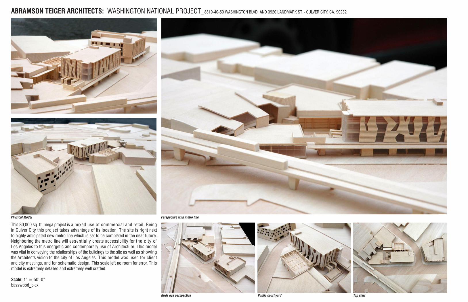
This 80,000 sq. ft. mega project is a mixed use of commercial and retail. Being in Culver City this project takes advantage of its location. The site is right next to highly anticipated new metro line which is set to be completed in the near future. Neighboring the metro line will essentially create accessibility for the city of Los Angeles to this energetic and contemporary use of Architecture. This model was vital in conveying the relationships of the buildings to the site as well as showing the Architects vision to the city of Los Angeles. This model was used for client and city meetings, and for schematic design. This scale left no room for error. This model is extremely detailed and extremely well crafted.
Scale: 1” = 50’-0”basswood_plex
ABRAMSON TEIGER ARCHITECTS: WASHINGTON NATIONAL PROJECT_8810-40-50 WASHINGTON BLVD. AND 3920 LANDMARK ST. - CULVER CITY, CA. 90232
Perspective with metro line
Birds eye perspective Public court yard Top view
Physical Model
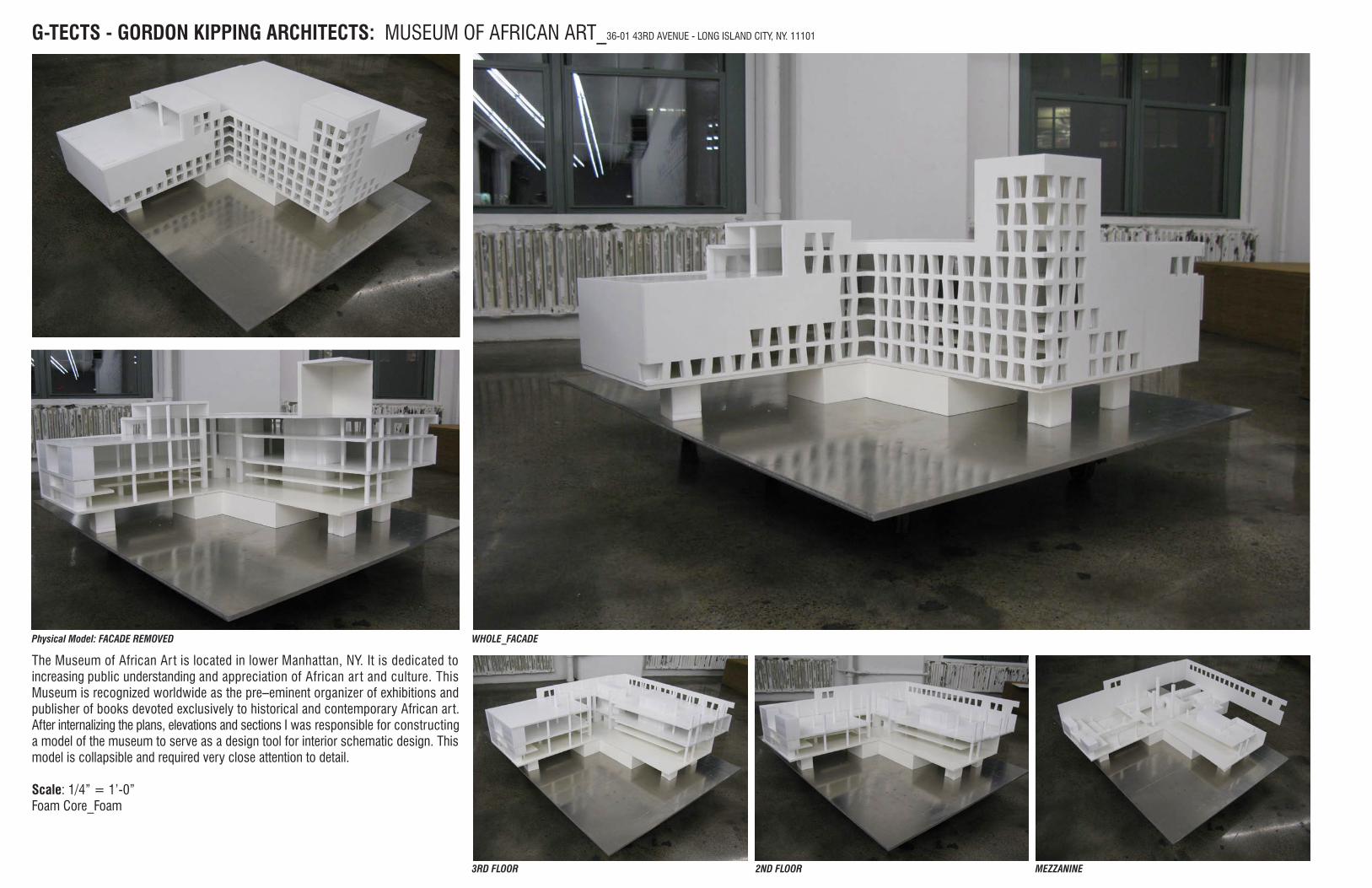
The Museum of African Ar t is located in lower Manhattan, NY. It is dedicated to increasing public understanding and appreciation of African ar t and culture. This Museum is recognized worldwide as the pre–eminent organizer of exhibitions and publisher of books devoted exclusively to historical and contemporary African art. After internalizing the plans, elevations and sections I was responsible for constructing a model of the museum to serve as a design tool for interior schematic design. This model is collapsible and required very close attention to detail.
Scale: 1/4” = 1’-0”Foam Core_Foam
G-TECTS - GORDON KIPPING ARCHITECTS: MUSEUM OF AFRICAN ART_36-01 43RD AVENUE - LONG ISLAND CITY, NY. 11101
WHOLE_FACADE
3RD FLOOR 2ND FLOOR MEZZANINE
Physical Model: FACADE REMOVED
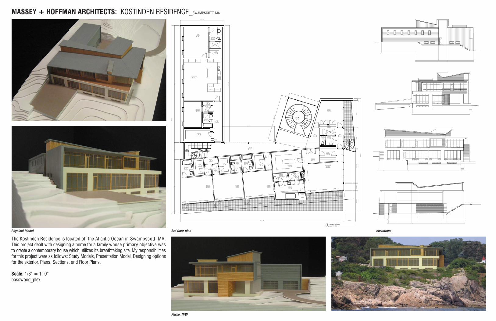
The Kostinden Residence is located off the Atlantic Ocean in Swampscott, MA. This project dealt with designing a home for a family whose primary objective was to create a contemporary house which utilizes its breathtaking site. My responsibilities for this project were as follows: Study Models, Presentation Model, Designing options for the exterior, Plans, Sections, and Floor Plans.
Scale: 1/8” = 1’-0”basswood_plex
MASSEY + HOFFMAN ARCHITECTS: KOSTINDEN RESIDENCE_SWAMPSCOTT, MA.
3rd floor plan
Persp. N/W
elevationsPhysical Model
DAVID ERVEN
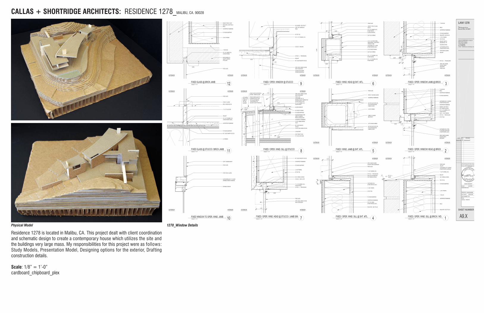
CALLAS + SHORTRIDGE ARCHITECTS1278 RESIDENCE
CALLAS + SHORTRIDGE ARCHITECTS1278 RESIDENCE
Residence 1278 is located in Malibu, CA. This project dealt with client coordination and schematic design to create a contemporary house which utilizes the site and the buildings very large mass. My responsibilities for this project were as follows: Study Models, Presentation Model, Designing options for the exterior, Drafting construction details.
Scale: 1/8” = 1’-0”cardboard_chipboard_plex
CALLAS + SHORTRIDGE ARCHITECTS: RESIDENCE 1278_MALIBU, CA. 90028
Physical Model 1278_Window Details

DAVID ERVEN
CALLAS + SHORTRIDGE ARCHITECTS: RESIDENCE 1278_MALIBU, CA. 90028
DAVID ERVEN
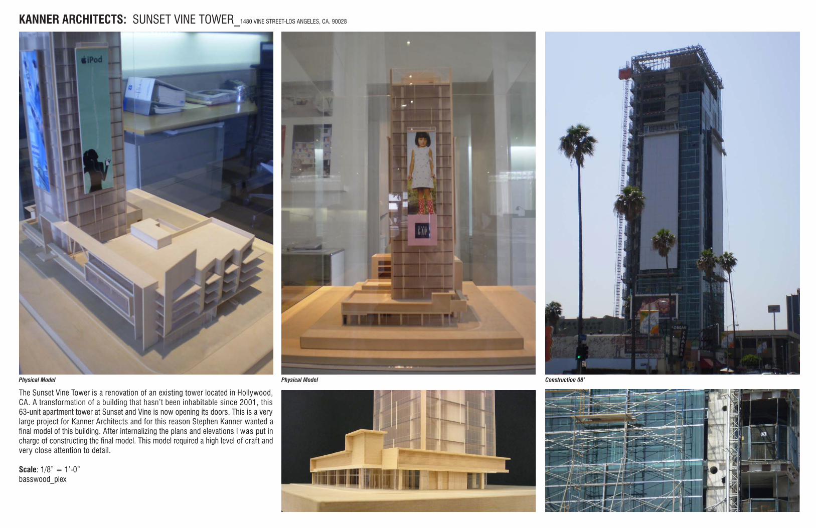
The Sunset Vine Tower is a renovation of an existing tower located in Hollywood, CA. A transformation of a building that hasn’t been inhabitable since 2001, this 63-unit apartment tower at Sunset and Vine is now opening its doors. This is a very large project for Kanner Architects and for this reason Stephen Kanner wanted a final model of this building. After internalizing the plans and elevations I was put in charge of constructing the final model. This model required a high level of craft and very close attention to detail.
Scale: 1/8” = 1’-0”basswood_plex
KANNER ARCHITECTS: SUNSET VINE TOWER_1480 VINE STREET-LOS ANGELES, CA. 90028
Construction 08’Physical Model Physical Model
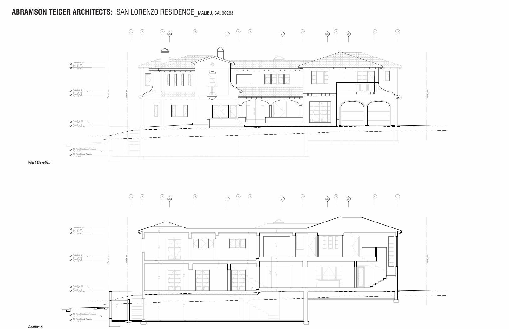
ABRAMSON TEIGER ARCHITECTS: SAN LORENZO RESIDENCE_MALIBU, CA. 90263
West Elevation
Section A
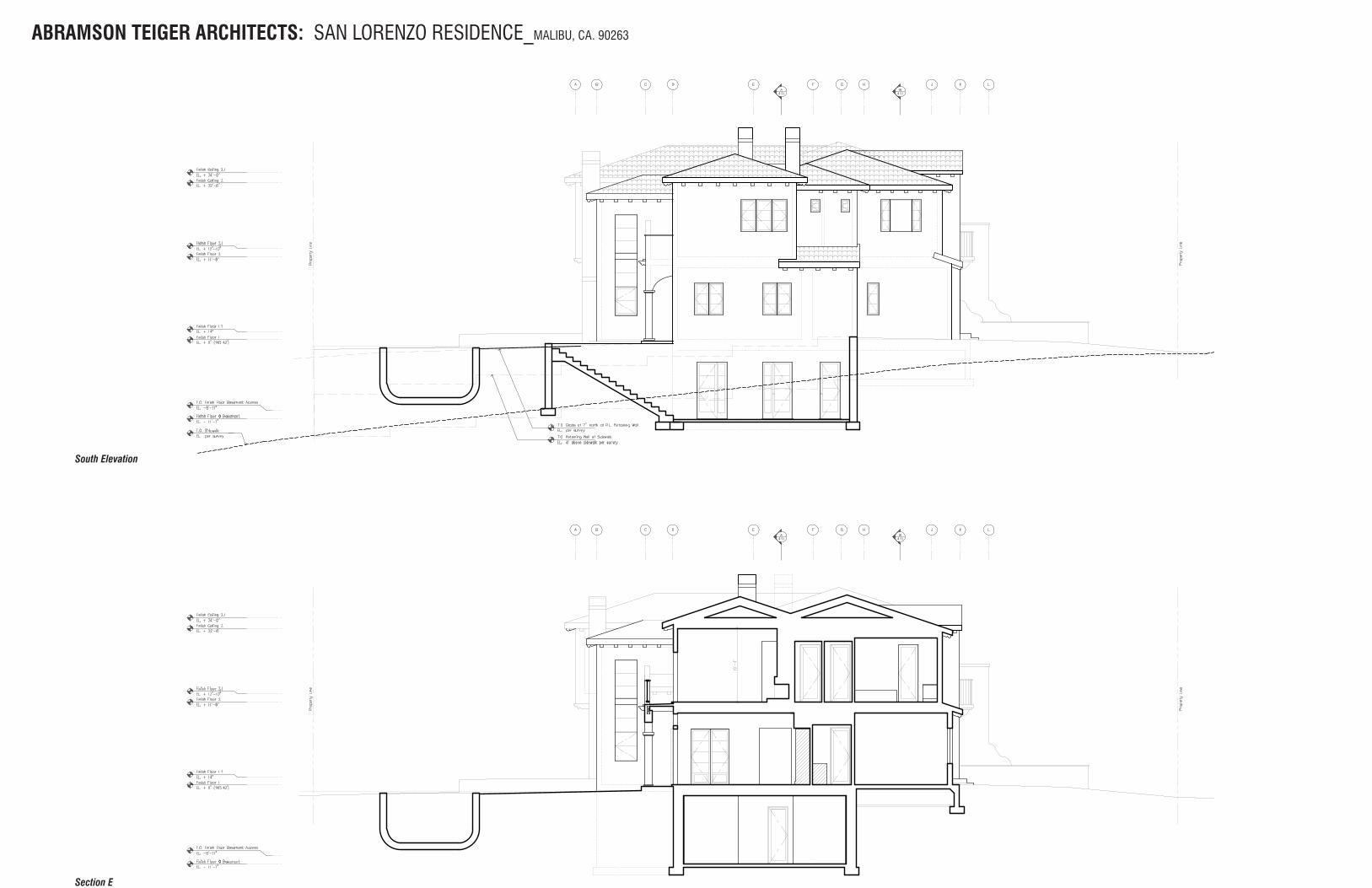
ABRAMSON TEIGER ARCHITECTS: SAN LORENZO RESIDENCE_MALIBU, CA. 90263
South Elevation
Section E
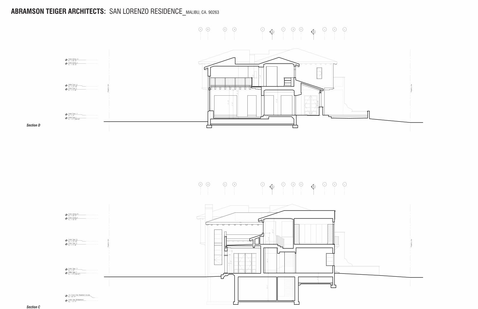
ABRAMSON TEIGER ARCHITECTS: SAN LORENZO RESIDENCE_MALIBU, CA. 90263
Section D
Section C
ABRAMSON TEIGER ARCHITECTS: SAN LORENZO RESIDENCE_MALIBU, CA. 90263
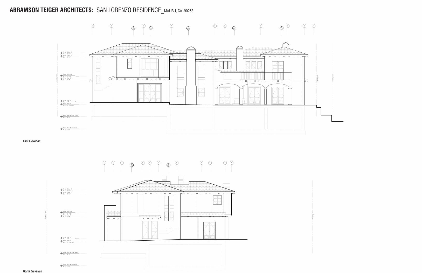
East Elevation
North Elevation
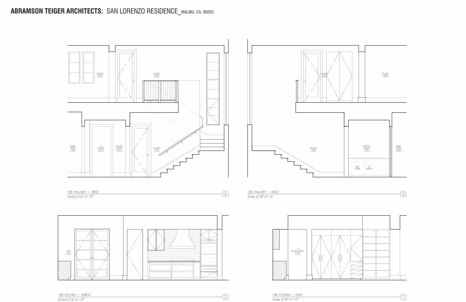
ABRAMSON TEIGER ARCHITECTS: SAN LORENZO RESIDENCE_MALIBU, CA. 90263
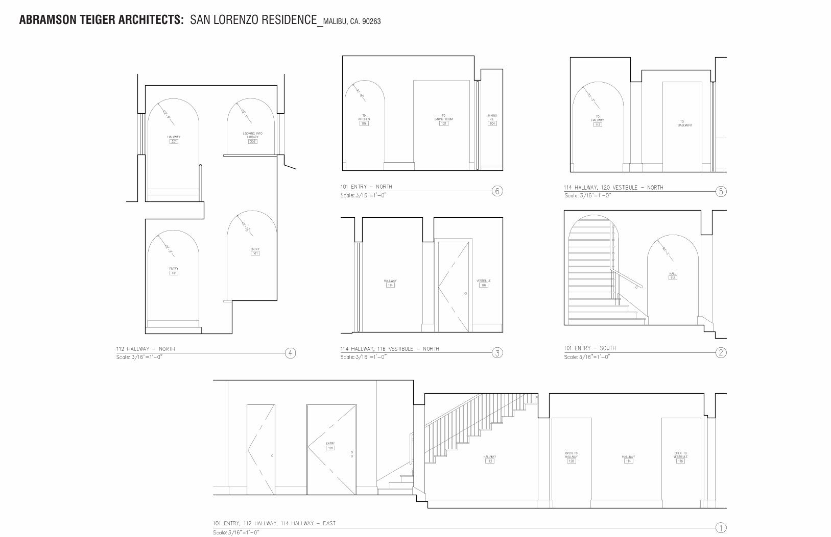
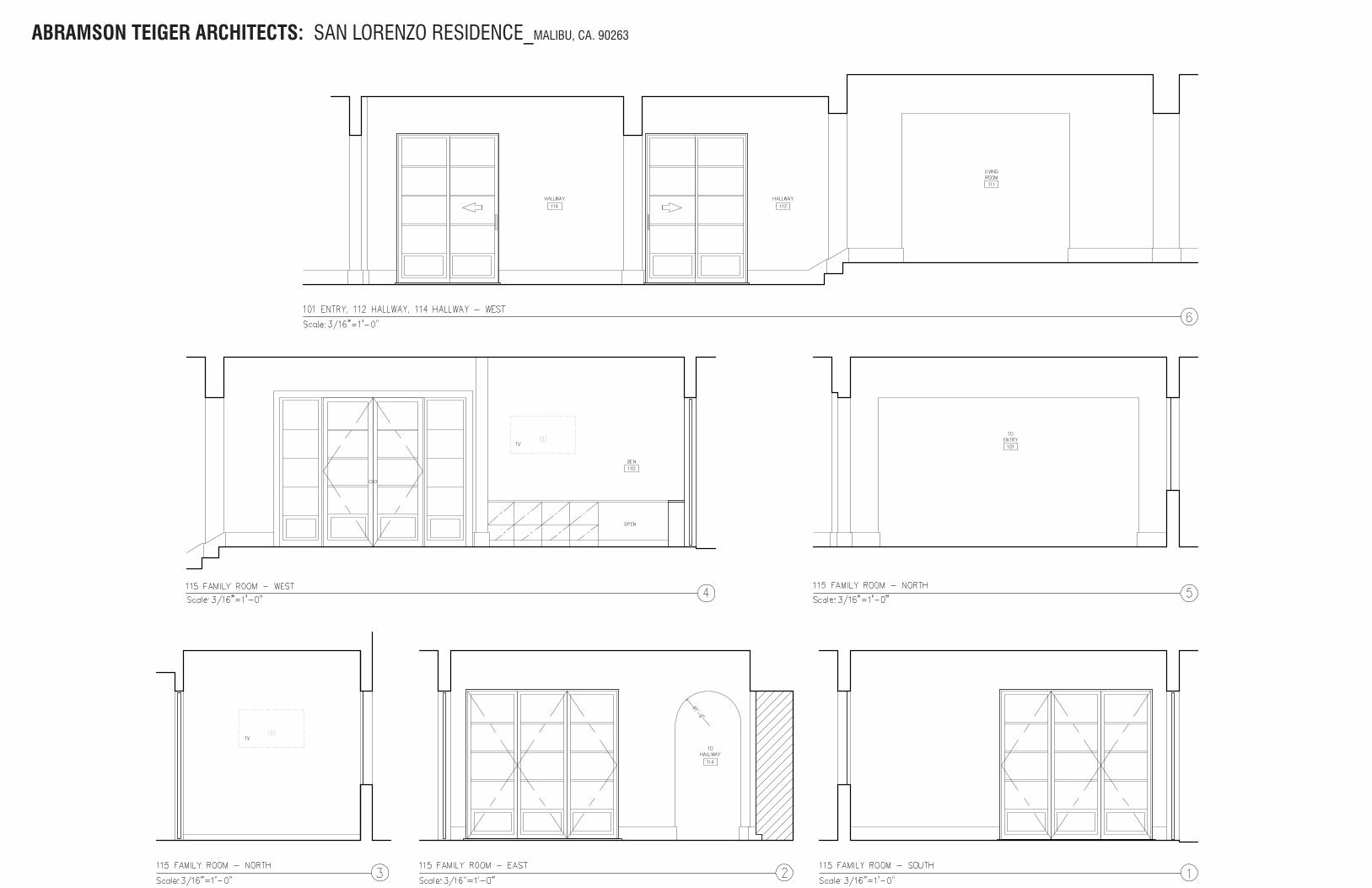
ABRAMSON TEIGER ARCHITECTS: SAN LORENZO RESIDENCE_MALIBU, CA. 90263
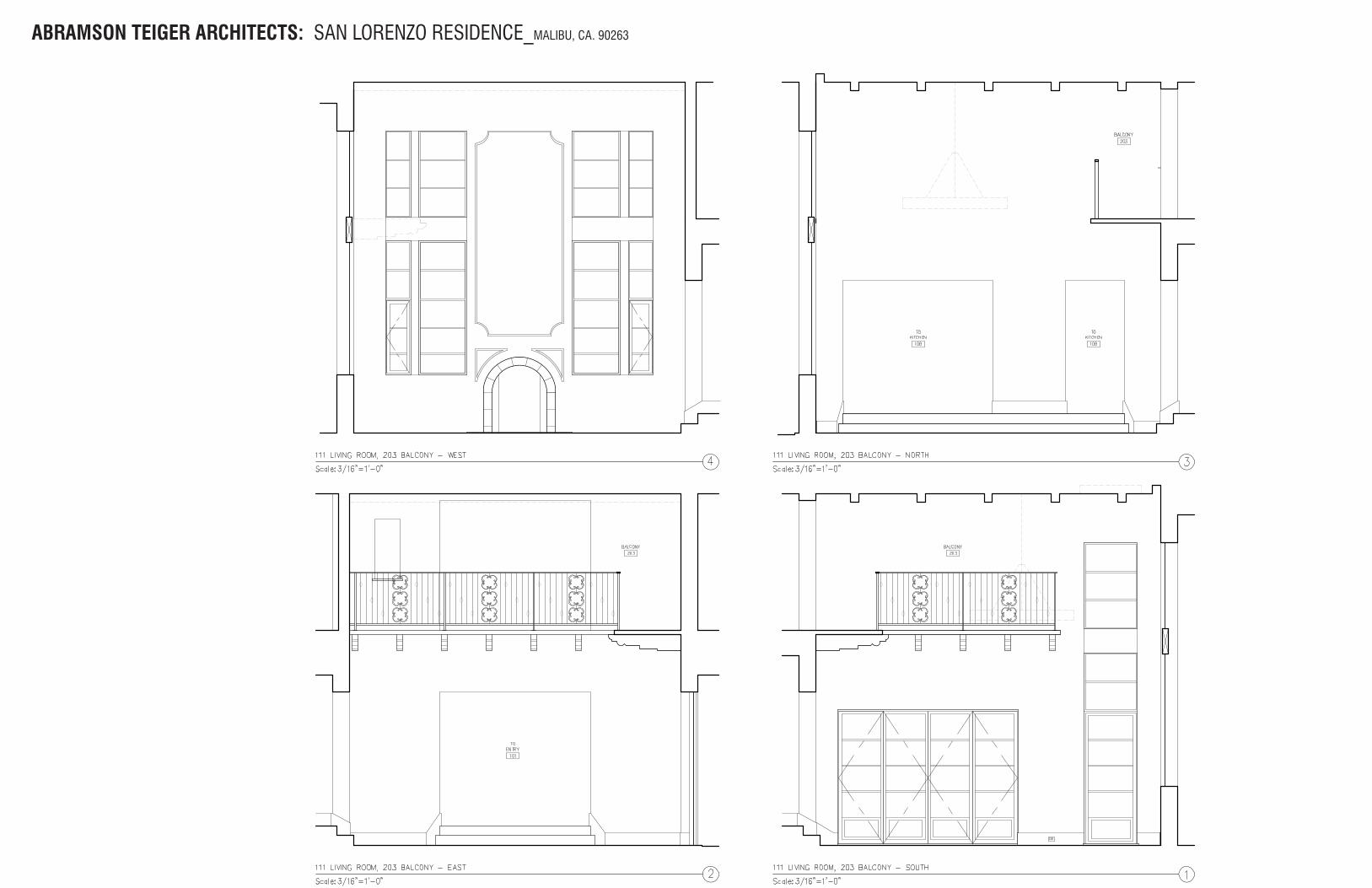
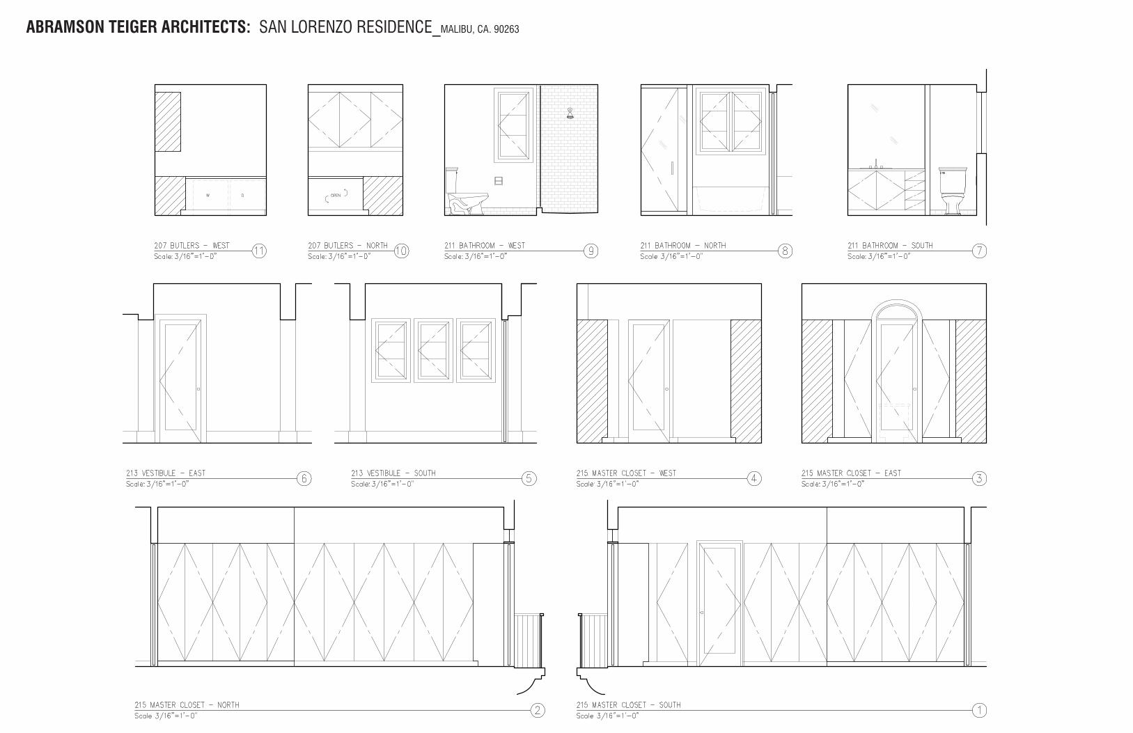
ABRAMSON TEIGER ARCHITECTS: SAN LORENZO RESIDENCE_MALIBU, CA. 90263
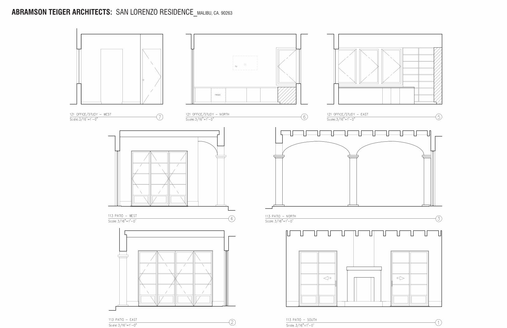
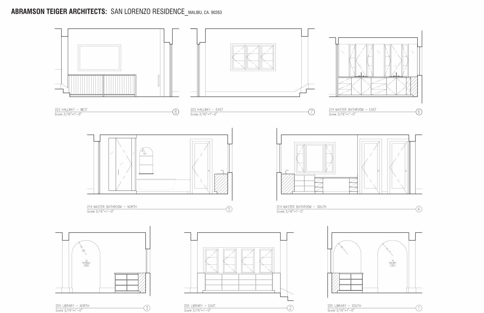
ABRAMSON TEIGER ARCHITECTS: SAN LORENZO RESIDENCE_MALIBU, CA. 90263
ABRAMSON TEIGER ARCHITECTS: SAN LORENZO RESIDENCE_MALIBU, CA. 90263
ABRAMSON TEIGER ARCHITECTS: SAN LORENZO RESIDENCE_MALIBU, CA. 90263
ABRAMSON TEIGER ARCHITECTS: SAN LORENZO RESIDENCE_MALIBU, CA. 90263
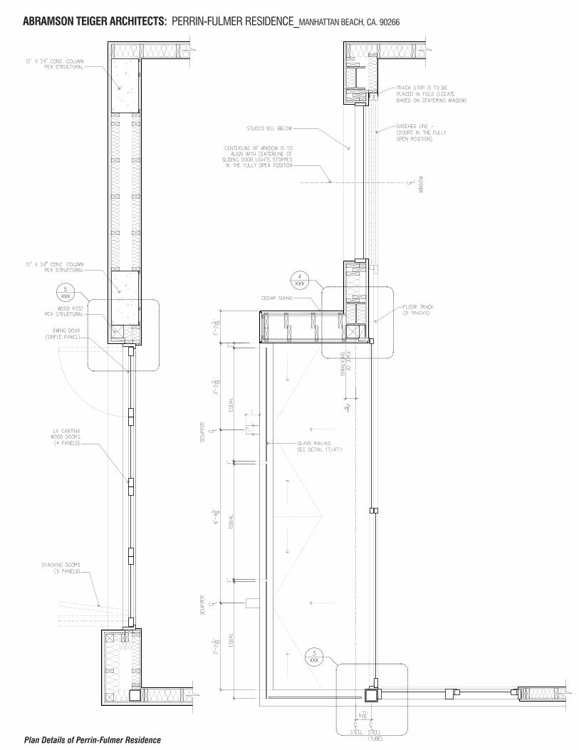
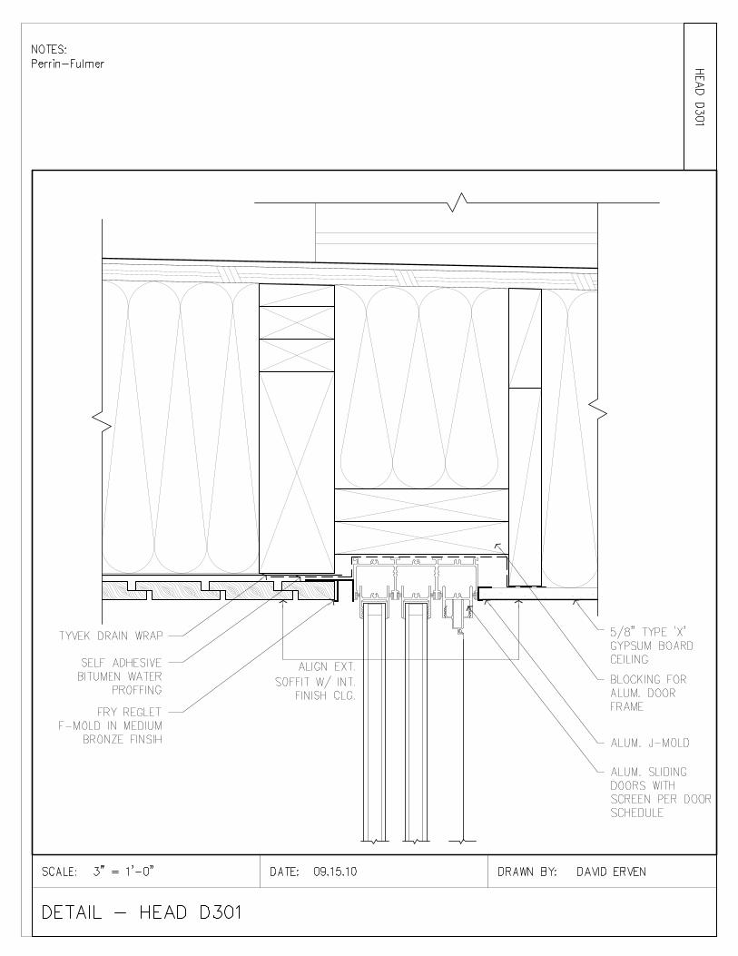
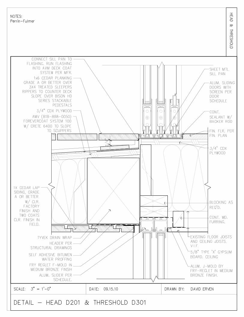
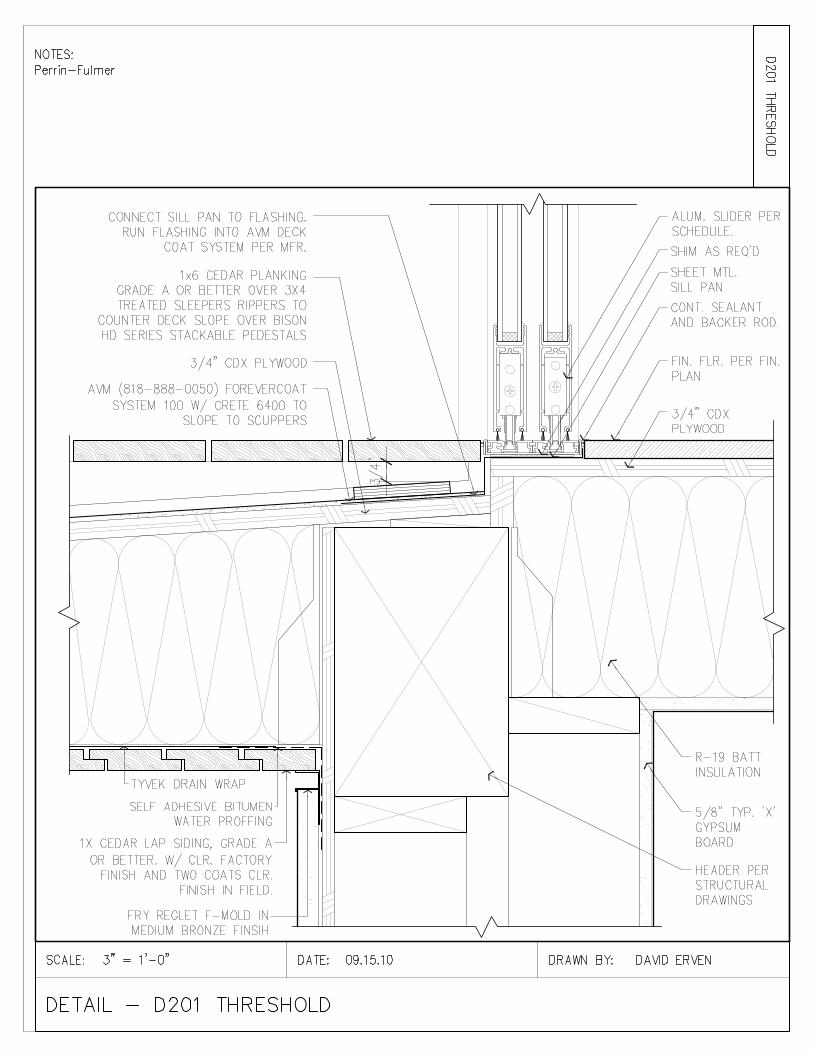
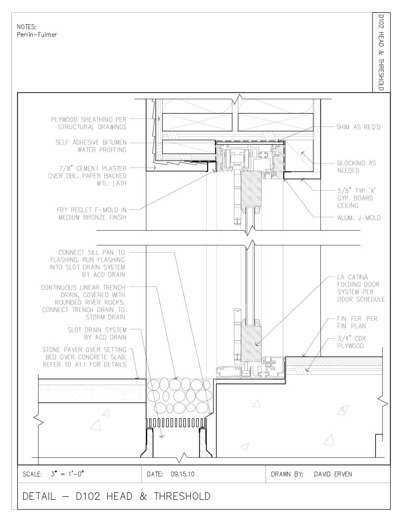
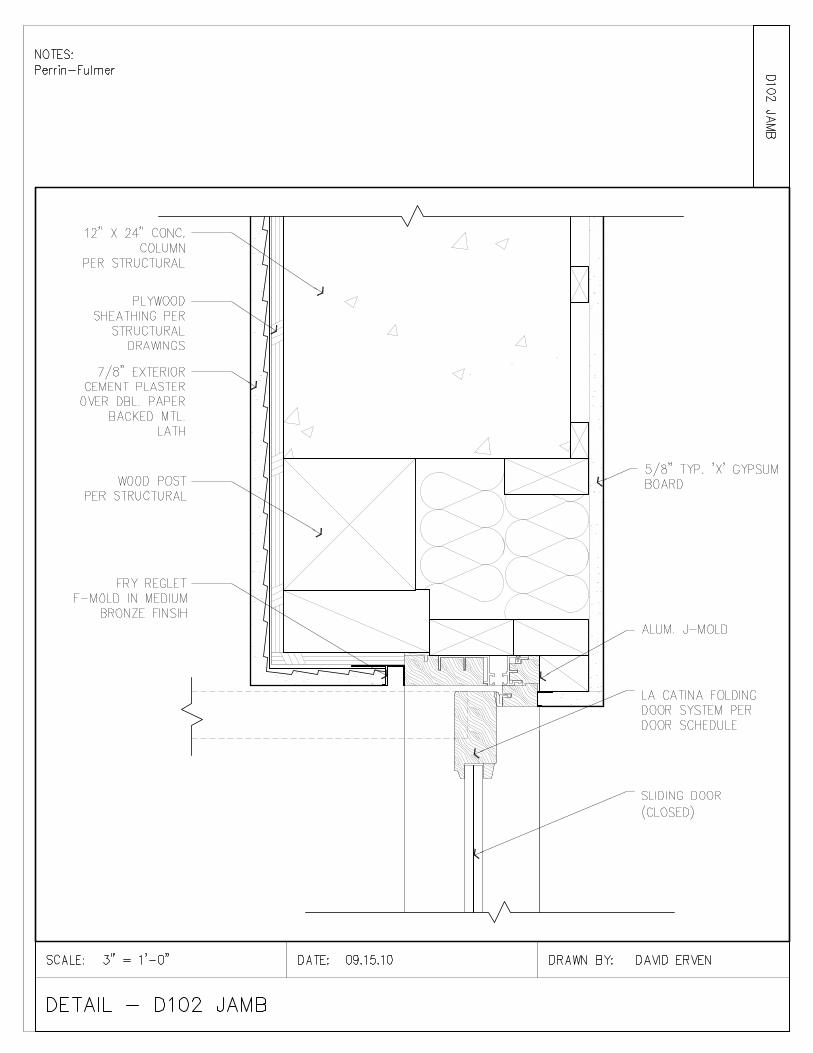
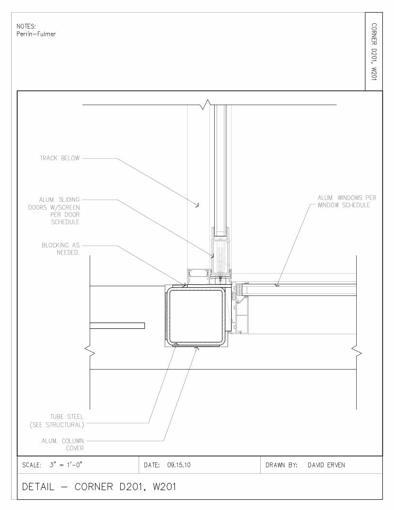
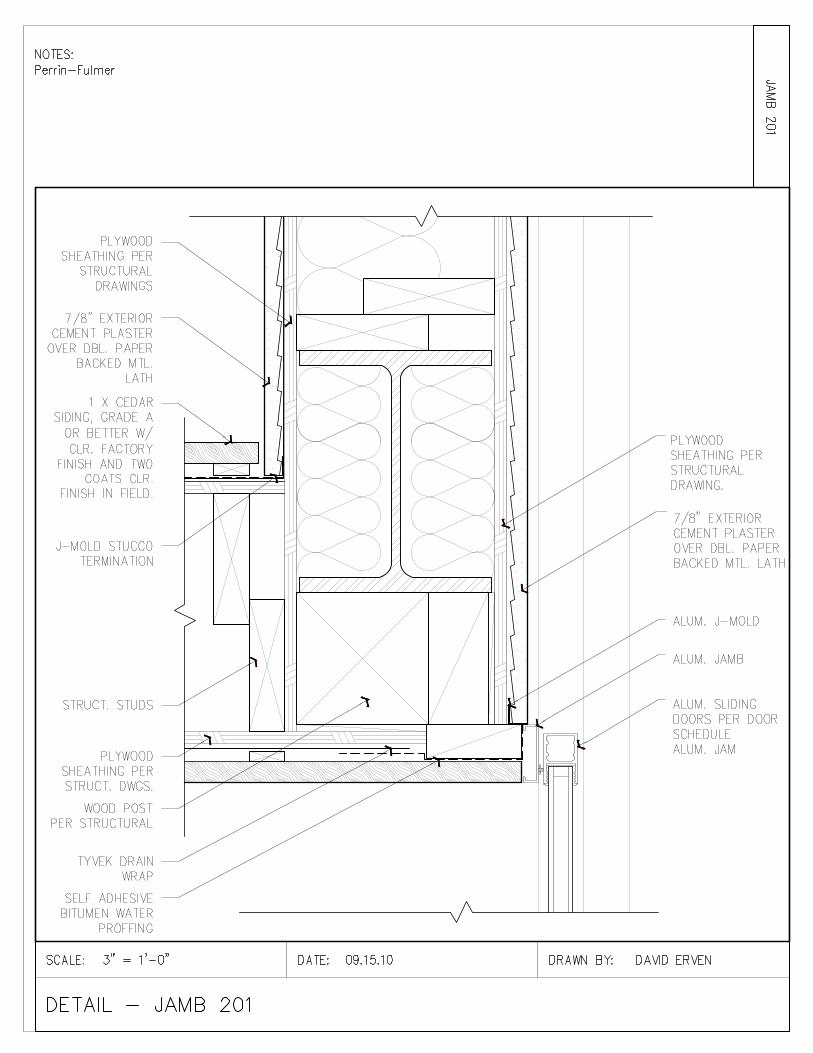
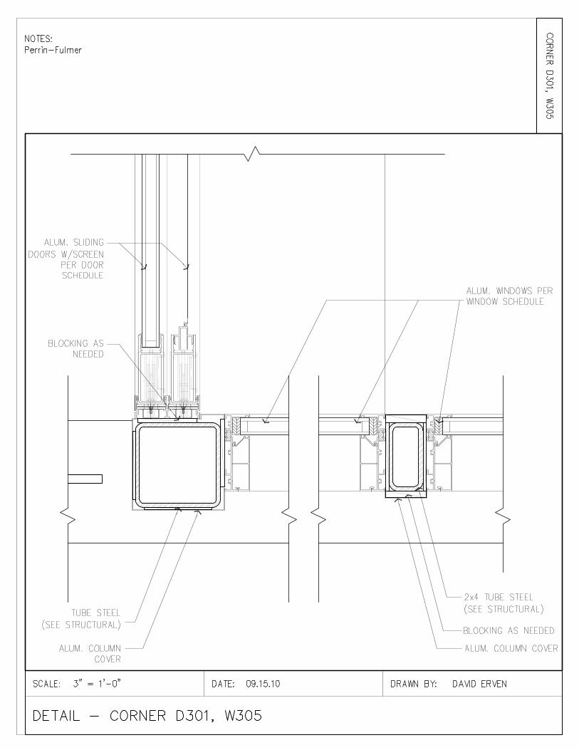
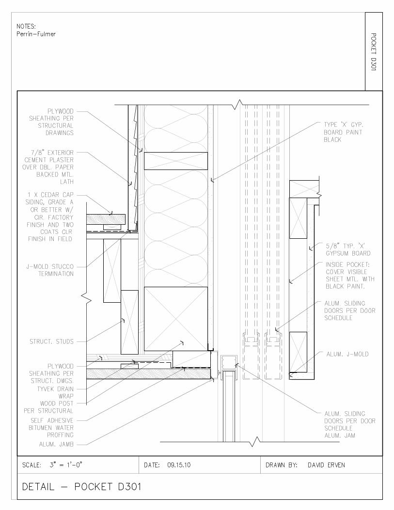
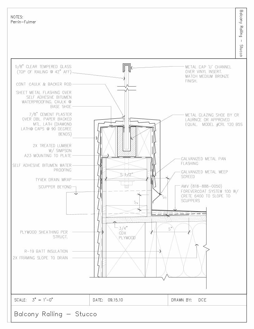
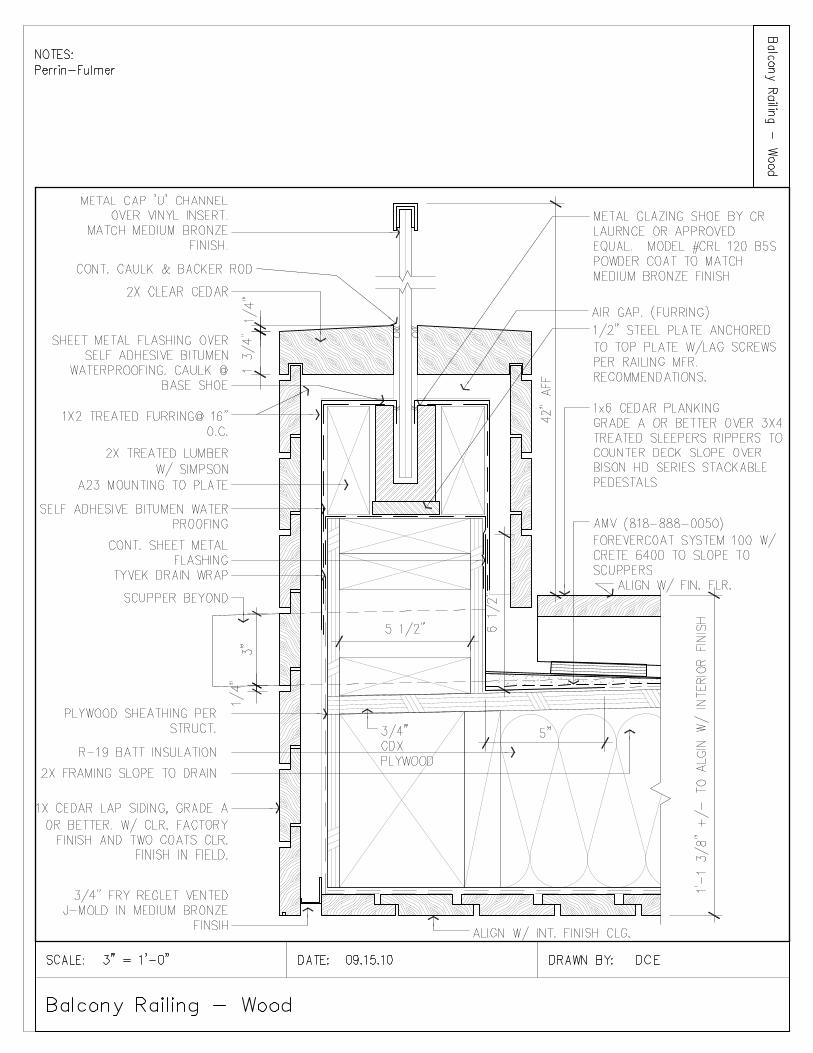
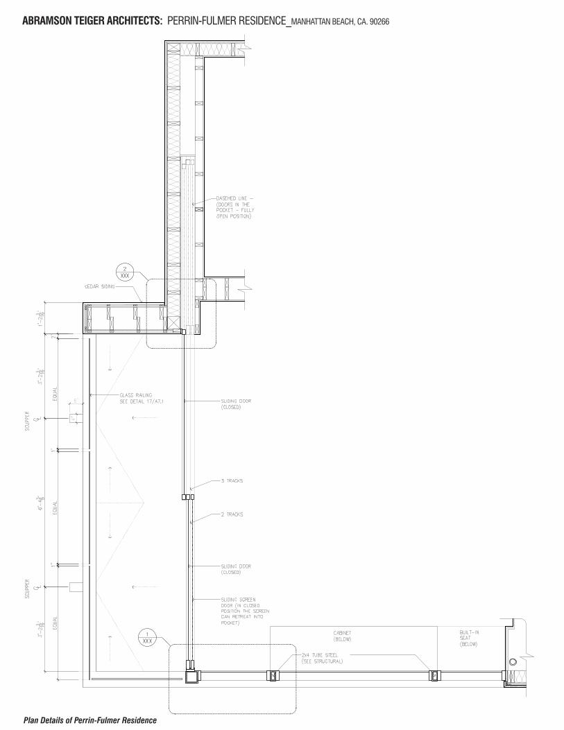
ABRAMSON TEIGER ARCHITECTS: PERRIN-FULMER RESIDENCE_MANHATTAN BEACH, CA. 90266
Plan Details of Perrin-Fulmer Residence
ABRAMSON TEIGER ARCHITECTS: PERRIN-FULMER RESIDENCE_MANHATTAN BEACH, CA. 90266
Plan Details of Perrin-Fulmer Residence