Embed Size (px)
Citation preview
1nuaire.co.uk 029 2085 8400 26. 01. 18. Leaflet Number 671679
The EMC Directive 2014/30/EUThe Low Voltage Directive2014/35/EU
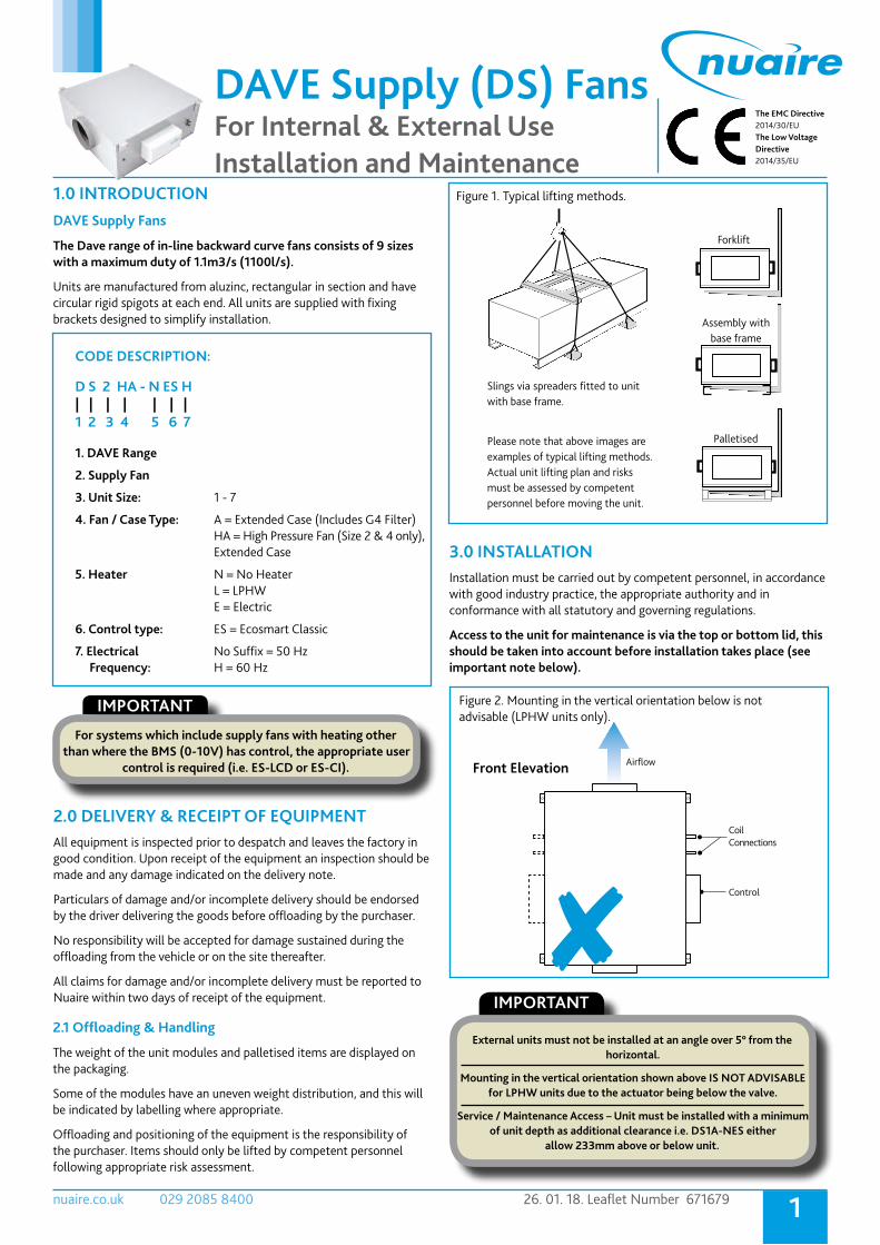
DAVE Supply (DS) FansFor Internal & External Use Installation and Maintenance
1.0 INTRODUCTIONDAVE Supply Fans
The Dave range of in-line backward curve fans consists of 9 sizes with a maximum duty of 1.1m3/s (1100l/s).
Units are manufactured from aluzinc, rectangular in section and have circular rigid spigots at each end. All units are supplied with fixing brackets designed to simplify installation.
3.0 INSTALLATIONInstallation must be carried out by competent personnel, in accordance with good industry practice, the appropriate authority and in conformance with all statutory and governing regulations.
Access to the unit for maintenance is via the top or bottom lid, this should be taken into account before installation takes place (see important note below).
IMPORTANT
For systems which include supply fans with heating other than where the BMS (0-10V) has control, the appropriate user
control is required (i.e. ES-LCD or ES-CI).
2.0 DELIVERY & RECEIPT OF EQUIPMENT All equipment is inspected prior to despatch and leaves the factory in good condition. Upon receipt of the equipment an inspection should be made and any damage indicated on the delivery note.
Particulars of damage and/or incomplete delivery should be endorsed by the driver delivering the goods before offloading by the purchaser.
No responsibility will be accepted for damage sustained during the offloading from the vehicle or on the site thereafter.
All claims for damage and/or incomplete delivery must be reported to Nuaire within two days of receipt of the equipment.
2.1 Offloading & Handling
The weight of the unit modules and palletised items are displayed on the packaging.
Some of the modules have an uneven weight distribution, and this will be indicated by labelling where appropriate.
Offloading and positioning of the equipment is the responsibility of the purchaser. Items should only be lifted by competent personnel following appropriate risk assessment.
Assembly withbase frame
Palletised
Forklift
Slings via spreaders fitted to unitwith base frame.
Please note that above images areexamples of typical lifting methods.Actual unit lifting plan and risksmust be assessed by competent personnel before moving the unit.
Figure 1. Typical lifting methods.
Front Elevation
Control
Airflow
Coil Connections
Figure 2. Mounting in the vertical orientation below is not advisable (LPHW units only).
IMPORTANT
External units must not be installed at an angle over 5° from the horizontal.
Mounting in the vertical orientation shown above IS NOT ADVISABLE for LPHW units due to the actuator being below the valve.
Service / Maintenance Access – Unit must be installed with a minimum of unit depth as additional clearance i.e. DS1A-NES either
allow 233mm above or below unit.
CODE DESCRIPTION:
D S 2 HA - N ES H| | | | | | |1 2 3 4 5 6 7
1. DAVE Range
2. Supply Fan
3. Unit Size: 1 - 7
4. Fan / Case Type: A = Extended Case (Includes G4 Filter) HA = High Pressure Fan (Size 2 & 4 only), Extended Case
5. Heater N = No Heater L = LPHW E = Electric
6. Control type: ES = Ecosmart Classic
7. Electrical No Suffix = 50 Hz Frequency: H = 60 Hz
2nuaire.co.uk 029 2085 8400 26. 01. 18. Leaflet Number 671679
Installation and Maintenance DAVE Supply (DS) Fans
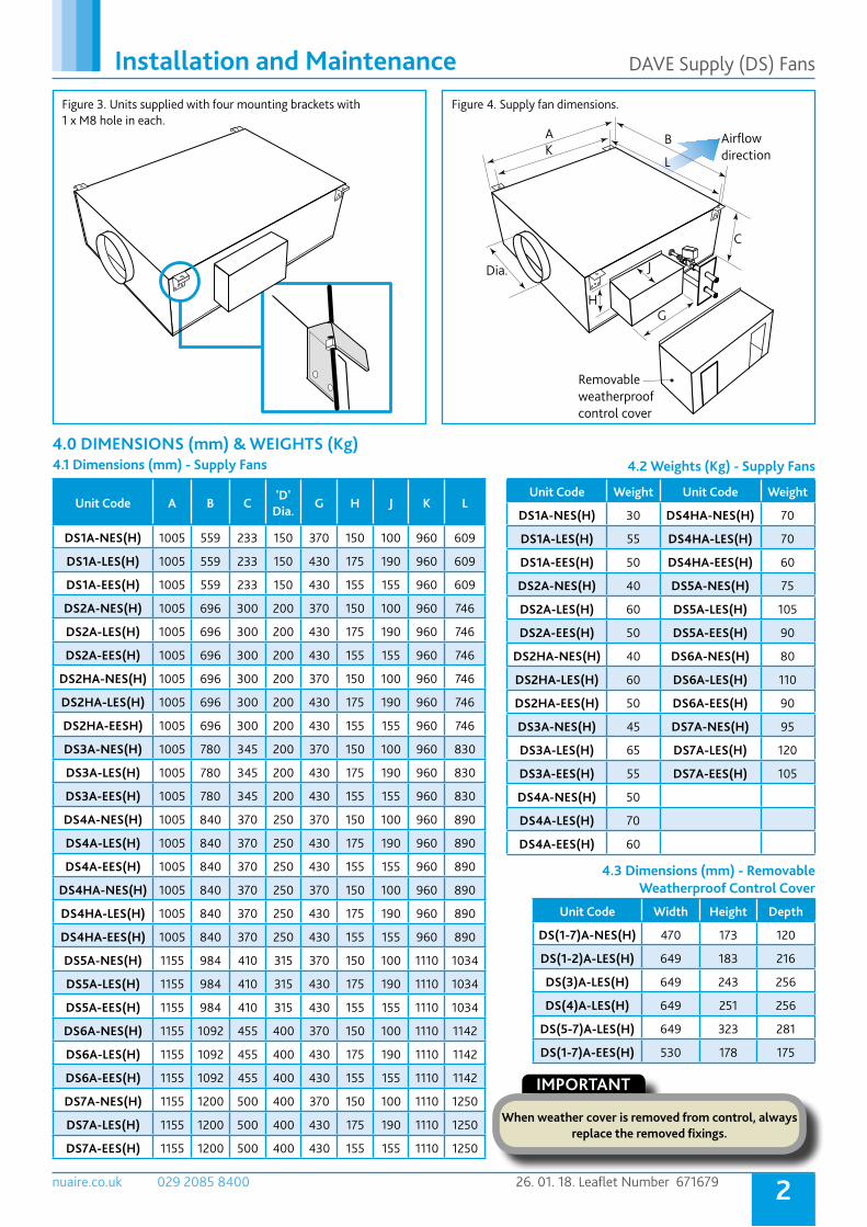
Figure 3. Units supplied with four mounting brackets with 1 x M8 hole in each.
Unit Code A B C'D'
Dia.G H J K L
DS1A-NES(H) 1005 559 233 150 370 150 100 960 609
DS1A-LES(H) 1005 559 233 150 430 175 190 960 609
DS1A-EES(H) 1005 559 233 150 430 155 155 960 609
DS2A-NES(H) 1005 696 300 200 370 150 100 960 746
DS2A-LES(H) 1005 696 300 200 430 175 190 960 746
DS2A-EES(H) 1005 696 300 200 430 155 155 960 746
DS2HA-NES(H) 1005 696 300 200 370 150 100 960 746
DS2HA-LES(H) 1005 696 300 200 430 175 190 960 746
DS2HA-EESH) 1005 696 300 200 430 155 155 960 746
DS3A-NES(H) 1005 780 345 200 370 150 100 960 830
DS3A-LES(H) 1005 780 345 200 430 175 190 960 830
DS3A-EES(H) 1005 780 345 200 430 155 155 960 830
DS4A-NES(H) 1005 840 370 250 370 150 100 960 890
DS4A-LES(H) 1005 840 370 250 430 175 190 960 890
DS4A-EES(H) 1005 840 370 250 430 155 155 960 890
DS4HA-NES(H) 1005 840 370 250 370 150 100 960 890
DS4HA-LES(H) 1005 840 370 250 430 175 190 960 890
DS4HA-EES(H) 1005 840 370 250 430 155 155 960 890
DS5A-NES(H) 1155 984 410 315 370 150 100 1110 1034
DS5A-LES(H) 1155 984 410 315 430 175 190 1110 1034
DS5A-EES(H) 1155 984 410 315 430 155 155 1110 1034
DS6A-NES(H) 1155 1092 455 400 370 150 100 1110 1142
DS6A-LES(H) 1155 1092 455 400 430 175 190 1110 1142
DS6A-EES(H) 1155 1092 455 400 430 155 155 1110 1142
DS7A-NES(H) 1155 1200 500 400 370 150 100 1110 1250
DS7A-LES(H) 1155 1200 500 400 430 175 190 1110 1250
DS7A-EES(H) 1155 1200 500 400 430 155 155 1110 1250
Unit Code Weight Unit Code Weight
DS1A-NES(H) 30 DS4HA-NES(H) 70
DS1A-LES(H) 55 DS4HA-LES(H) 70
DS1A-EES(H) 50 DS4HA-EES(H) 60
DS2A-NES(H) 40 DS5A-NES(H) 75
DS2A-LES(H) 60 DS5A-LES(H) 105
DS2A-EES(H) 50 DS5A-EES(H) 90
DS2HA-NES(H) 40 DS6A-NES(H) 80
DS2HA-LES(H) 60 DS6A-LES(H) 110
DS2HA-EES(H) 50 DS6A-EES(H) 90
DS3A-NES(H) 45 DS7A-NES(H) 95
DS3A-LES(H) 65 DS7A-LES(H) 120
DS3A-EES(H) 55 DS7A-EES(H) 105
DS4A-NES(H) 50
DS4A-LES(H) 70
DS4A-EES(H) 60
Dia.
AK
B
L
C
J
HG
Removable weatherproof control cover
Airflowdirection
Unit Code Width Height Depth
DS(1-7)A-NES(H) 470 173 120
DS(1-2)A-LES(H) 649 183 216
DS(3)A-LES(H) 649 243 256
DS(4)A-LES(H) 649 251 256
DS(5-7)A-LES(H) 649 323 281
DS(1-7)A-EES(H) 530 178 175
4.0 DIMENSIONS (mm) & WEIGHTS (Kg)4.1 Dimensions (mm) - Supply Fans 4.2 Weights (Kg) - Supply Fans
4.3 Dimensions (mm) - Removable Weatherproof Control Cover
IMPORTANT
When weather cover is removed from control, always replace the removed fixings.
Figure 4. Supply fan dimensions.

3nuaire.co.uk 029 2085 8400 26. 01. 18. Leaflet Number 671679
Installation and Maintenance DAVE Supply (DS) Fans
5.0 INSTALLING THE WATER CIRCUIT It is recommended that all joints are checked for leaks when commissioning and a strainer and isolating valves are fitted (by others) for ease of maintenance.
The Low Pressure Hot Water (LPHW) heating coil shall be factory fitted with a 2-port pressure independent balancing and control valve complete with actuator. All components pre-piped, assembled and tested by the manufacturer.
Ecosmart frost protection is activated on any Ecosmart unit fitted with LPHW heating, when the outlet air temperature is 4ºC or below.
The unit reacts by shutting down the fan to prevent a ‘wind chill’ effect reducing the temperature to a point whereby the coil could freeze and burst. The unit will also drive open the LPHW valve to a fully open position to allow full water flow through the coil and the main PCB will close the ‘Heat demand’ contacts. These contacts could be used to send a signal to activate the boiler and/or valve to open to provide heat if not already doing so.
IMPORTANT
LPHW supply units have a 2 Port Pressure Independent control Valve (PICV) fitted. If the LPHW system is not run via a ‘Constant Pressure Pump’ then provision must be made to incorporate a ‘Bypass’ into the system to maintain a minimum level of flow through
the pump when the 2 Port PICV is closed.
Removable weatherproof cover
Ecosmart control
Remove weather cover but leave pipe plate in position (as above) to support pipes during installation.Pipe connection supplied with unit is 22mm Ø.
Figure 5. Water circuit pipe support.
5.1 2 Port Pressure Independent Balancing Control Valve - Setting Instruction
5.2 Valve Settings for DAVE Supply (DS) Units (1 - 7)5.2.1 Units 1, 2 & 2H 5.2.2 Units 3, 4 & 4H 5.2.3 Units 5, 6 & 7
DN20 L/h L/s GPM
20% 180 0.050 0.80
25% 225 0.063 1.00
30% 270 0.075 1.20
35% 315 0.088 1.40
40% 360 0.100 1.60
45% 405 0.113 1.80
50% 450 0.125 2.00
55% 495 0.138 2.20
60% 540 0.150 2.40
65% 585 0.163 2.60
70% 630 0.175 2.80
75% 675 0.188 3.00
80% 720 0.200 3.20
85% 765 0.213 3.40
90% 810 0.225 3.60
95% 855 0.238 3.80
100% 900 0.250 4.00
DN25 L/h L/s GPM
20% 340 0.094 1.50
25% 425 0.118 1.88
30% 510 0.142 2.25
35% 595 0.165 2.63
40% 680 0.189 3.00
45% 765 0.213 3.38
50% 850 0.236 3.75
55% 935 0.260 4.13
60% 1020 0.283 4.5
65% 1105 0.307 4.88
70% 1190 0.331 5.25
75% 1275 0.354 5.63
80% 1360 0.378 6.00
85% 1445 0.401 6.38
90% 1530 0.425 6.75
95% 1615 0.449 7.13
100% 1700 0.472 7.50
DN32 L/h L/s GPM
20% 640 0.178 2.80
25% 800 0.222 3.50
30% 960 0.267 4.20
35% 1120 0.311 4.90
40% 1280 0.356 5.60
45% 1440 0.400 6.30
50% 1600 0.444 7.00
55% 1760 0.489 7.70
60% 1920 0.533 8.40
65% 2080 0.578 9.10
70% 2240 0.622 9.80
75% 2400 0.667 10.50
80% 2560 0.711 11.20
85% 2720 0.756 11.90
90% 2880 0.800 12.60
95% 3040 0.844 13.30
100% 3200 0.889 14.00
Figure 6. Actuator removal. Figure 7. Unlock Adjusting Collar.

4nuaire.co.uk 029 2085 8400 26. 01. 18. Leaflet Number 671679
Installation and Maintenance DAVE Supply (DS) Fans
Figure 10. Volt free relay contacts.
6.0 ELECTRICAL CONNECTION 6.1 Wiring Connections for Units With Ecosmart Control
Unit details including Full Load Current, Voltage, fan speed etc. can be found on the unit label.
6.1.1 Mains Connections
Mains cables should be suitably sized and terminated at the terminals shown on the appropriate diagram.
6.1.2 Control Connections
3 IDC plug-in Net connectors are provided for the connection of compatible sensors, manual controls and for linking the fans together under a common control. If more than 3 connections are required, the junction box (product code ES-JB) should be used (see data cable installation).
Figure 8. 'Net' connection for Ecosmart devices.
6.1.3 Switched Live (SL) Terminal
Mains cables should be suitably sized and terminated at the terminals shown on the appropriate diagram.
6.1.4 Control Connections
A signal of 100-230V / 220V a.c. will activate the fan from either its off state or trickle state (see setting to work-trickle switch). When the SL is disconnected the fan will over-run (see setting to work-timer adjustment).
Do not take this signal from an isolating transformer.
6.1.5 Volt Free Relay Contacts
Volt free contacts are not fused, if these are used to power any external equipment, the installer must provide adequate fusing or other protection. These contacts are rated at 5A resistive, 0.5A inductive.
N E L SL
Remove link if switched live signal, an enabler or BMS signal is connected.
Terminals or PCB
Mains connection pre-wired230V 50Hz 1ph / 220V 60Hz 1ph
Figure 9. SL terminal.
RUN FAULT
Run signal Fault signal
Run Connections = Contacts are closed when the fan is running. Fault Connections - No Fault = Contacts are closed. Fault Connections - Fault = Contacts are open. Heat Demand = Contacts closed when heating is selected. Cooling Demand = Contacts close when cooling selected. Do not use this contact to switch compressors directly. Frost Alarm = Contacts close when air off temperature is 40°C or below. Fan shuts down, valve opens and the heat demand contacts activated.
6.1.6 Data Cable Installation
A 4-core SELV data cable is used to connect devices. Do not run data cable in the same conduit as the mains cables and ensure there is a 50mm separation between the data cable and other cables. The maximum cable run between any two devices is 300m when it is installed in accordance with the instructions.
Please note that the total data cable length used in any system must be less than 1000m. Keep the number of cable joints to a minimum to ensure the best data transmission efficiency between devices.
6.1.7 Maximum Number of Devices
The maximum number of devices (including fans) that can be connected together via the cable is 32, irrespective of their functions.
6.1.8 Other Low Voltage Cables
Follow the basic principle (as 6.1.6). Keep the cable run as short as possible, less than 50 metres.
LED indication for units with Ecosmart Control
PWR GREEN: Power on & OK. RED: To much power is taken by peripherals or there is a short circuit in the net cable. Check the cable and use a junction box (ES-JB) to connect some of the peripherals. Standby LED on when fan is not running. Fan 1 GREEN: Fan 1 is running, RED: Fan 1 faulty. Fan 2 GREEN: Fan 2 is running, RED: Fan 2 faulty (Twinfan only). Heating* GREEN: Heating selected RED: Heating not selected. Cooling* Not applicable. See note. Fault LED on when a fault is present on unit. Frost* Applicable with LPHW only. See note. Tx LED on when the controller is transmitting data. Rx LED on when the controller is receiving data.
* Note that the control panel is common to all the Ecosmart classic products and will have indicators for functions that are not available in this particular fan. However these indicators will not be illuminated.
LED indicators
Min Max SL run on
Trickle Test
10
PwrStandbyFan 1 Fan 2 HeatingCoolingFaultFrostTxRx
MIN = Minimum speed adjustment
MAX = Maximum speed adjustment
SL Run on = Switched Live Run-On Timer adjustment
TRICKLE = Selects trickle running: 0 = off, 1 = selected
TEST = Test button
Figure 11. Commissioning panel.
5nuaire.co.uk 029 2085 8400 26. 01. 18. Leaflet Number 671679
Installation and Maintenance DAVE Supply (DS) Fans
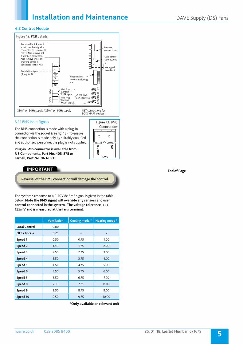
6.2 Control Module
6.2.1 BMS Input Signals
The BMS connection is made with a plug-in connector via the socket (see fig. 13). To ensure the connection is made only by suitably qualified and authorised personnel the plug is not supplied.
Plug-in BMS connector is available from: R S Components, Part No. 403-875 or Farnell, Part No. 963-021.
0 - 10V
0V
BMS
Figure 13. BMS Connections
IMPORTANT
Reversal of the BMS connection will damage the control.
The system’s response to a 0-10V dc BMS signal is given in the table below. Note the BMS signal will override any sensors and user control connected in the system. The voltage tolerance is +/- 125mV and is measured at the fans terminal.
Ventilation Cooling mode * Heating mode *
Local Control 0.00 - -
OFF / Trickle 0.25 - -
Speed 1 0.50 0.75 1.00
Speed 2 1.50 1.75 2.00
Speed 3 2.50 2.75 3.00
Speed 4 3.50 3.75 4.00
Speed 5 4.50 4.75 5.00
Speed 6 5.50 5.75 6.00
Speed 7 6.50 6.75 7.00
Speed 8 7.50 7.75 8.00
Speed 9 8.50 8.75 9.00
Speed 10 9.50 9.75 10.00
*Only available on relevant unit
Volt Free
0.5A inductive
Contact RUN signal 5A resistiveVolt Free Contact FAULT signal
NLSLDP
RUN
FAULT
CLNRET
Switc
if a BMS is connected.Also remove link if an enabling device is connected in the 'NET'
Remove this link wire if a switched live signal is connected to terminal SLNOTE: Also remove link
h live signal(if required)
NET connections for
No user
ECOSMART devices
connections
connectionsCO2 sensor
0
ECO
SMAR
T N
ET
+ve signalfrom BMS
Ribbon cableto commissioningbox
230V 1ph 50Hz supply / 220V 1ph 60Hz supply
End of Page
Figure 12. PCB details.

6nuaire.co.uk 029 2085 8400 26. 01. 18. Leaflet Number 671679
Installation and Maintenance DAVE Supply (DS) Fans
7.0 WIRING DIAGRAMS7.1 DS1-7 with No Heater
IMPORTANT
Isolation - Before commencing work, make sure that the unit and Nuaire control are electrically isolated from the mains supply.
Figure 14. DS1-7 with no heater.
7.2 DS1-7 with LPHW Heater
Figure 15. DS1-7 with LPHW heater.
Note: Local isolator (by others) All inter-connections between circuit boards, blowers and sensors are made at the factory. Remove link wire if switched live signal, an enabler or BMS signal is connected.
FROST PROTECTION (LPHW) NOTE: Ecosmart frost protection is activated when the outlet air of the unit is 4oC or below, when this temperature is reached, the unit reacts by shutting down the fan to prevent a ‘wind chill’ effect reducing the temperature to a point whereby the coil could freeze and burst. The unit will also drive open the LPHW valve to a fully open position to allow full water flow through the coil and the main PCB will close the ‘Heat demand’ contacts. These contacts could be used to send a signal to activate the boiler and/or valve to open to provide heat if not already doing so.
Note: Local isolator (by others) All inter-connections between circuit boards, blowers and sensors are made at the factory. Remove link wire if switched live signal, an enabler or BMS signal is connected.
7nuaire.co.uk 029 2085 8400 26. 01. 18. Leaflet Number 671679
Installation and Maintenance DAVE Supply (DS) Fans
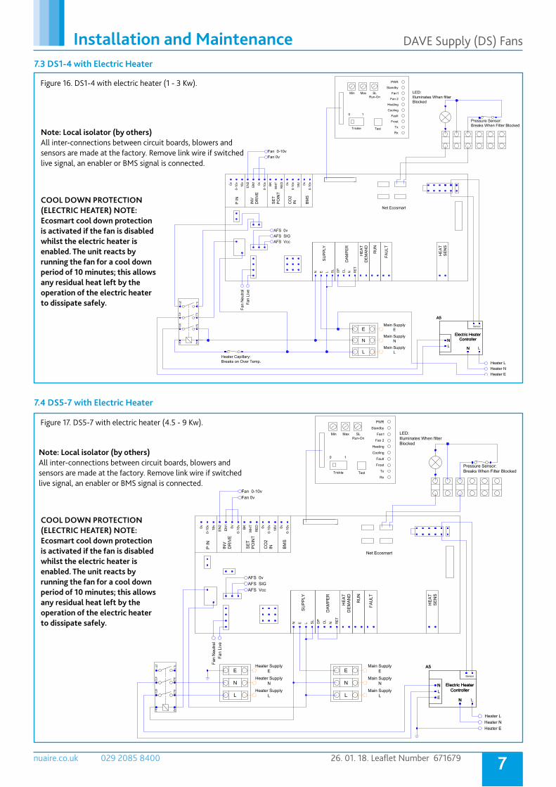
7.3 DS1-4 with Electric Heater
Figure 16. DS1-4 with electric heater (1 - 3 Kw).
7.4 DS5-7 with Electric Heater
Figure 17. DS5-7 with electric heater (4.5 - 9 Kw).
Note: Local isolator (by others) All inter-connections between circuit boards, blowers and sensors are made at the factory. Remove link wire if switched live signal, an enabler or BMS signal is connected.
Note: Local isolator (by others) All inter-connections between circuit boards, blowers and sensors are made at the factory. Remove link wire if switched live signal, an enabler or BMS signal is connected.
COOL DOWN PROTECTION (ELECTRIC HEATER) NOTE: Ecosmart cool down protection is activated if the fan is disabled whilst the electric heater is enabled. The unit reacts by running the fan for a cool down period of 10 minutes; this allows any residual heat left by the operation of the electric heater to dissipate safely.
COOL DOWN PROTECTION (ELECTRIC HEATER) NOTE: Ecosmart cool down protection is activated if the fan is disabled whilst the electric heater is enabled. The unit reacts by running the fan for a cool down period of 10 minutes; this allows any residual heat left by the operation of the electric heater to dissipate safely.
8nuaire.co.uk 029 2085 8400 26. 01. 18. Leaflet Number 671679
Installation and Maintenance DAVE Supply (DS) Fans
8.0 MAINTENANCE The first maintenance should be carried out three months after commissioning and thereafter at 12 monthly intervals.
General Cleaning and inspection - Electrically isolate before commencing work. Remove the top or the bottom cover and carefully clean out the interior as necessary. Check all parts for security and that the impeller rotates freely, taking care not to disturb the balance. Ensure all control components are secure and clean, refit the cover.
Lubrication - Motors are fitted with sealed for life bearings and do not require any lubrication.
Filter care/replacement - The filter (where applicable) will require cleaning on a regular basis. The frequency of the cleaning operation will depend on the site conditions.
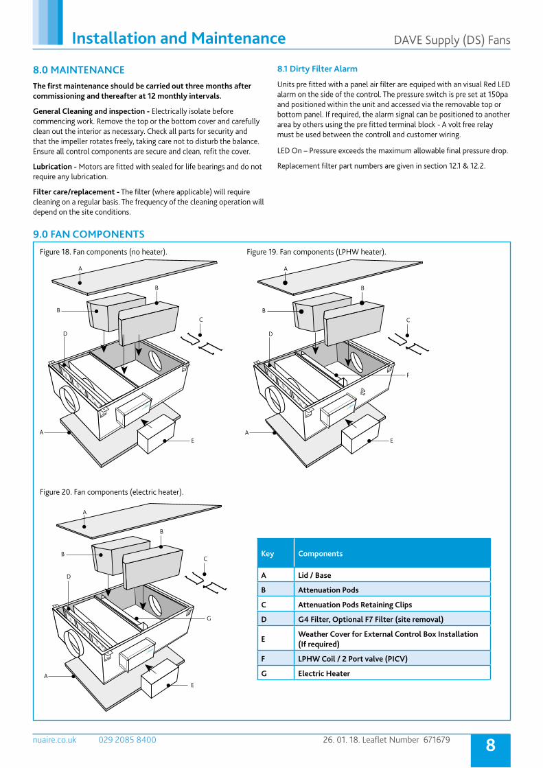
9.0 FAN COMPONENTS
Key Components
A Lid / Base
B Attenuation Pods
C Attenuation Pods Retaining Clips
D G4 Filter, Optional F7 Filter (site removal)
EWeather Cover for External Control Box Installation (If required)
F LPHW Coil / 2 Port valve (PICV)
G Electric Heater
A
B
AE
D
B
A
BC
AE
D
B
F
C
A
B
AE
D
B
G
C
Figure 18. Fan components (no heater). Figure 19. Fan components (LPHW heater).
Figure 20. Fan components (electric heater).
8.1 Dirty Filter Alarm
Units pre fitted with a panel air filter are equiped with an visual Red LED alarm on the side of the control. The pressure switch is pre set at 150pa and positioned within the unit and accessed via the removable top or bottom panel. If required, the alarm signal can be positioned to another area by others using the pre fitted terminal block - A volt free relay must be used between the controll and customer wiring.
LED On – Pressure exceeds the maximum allowable final pressure drop.
Replacement filter part numbers are given in section 12.1 & 12.2.
9nuaire.co.uk 029 2085 8400 26. 01. 18. Leaflet Number 671679
Installation and Maintenance DAVE Supply (DS) Fans
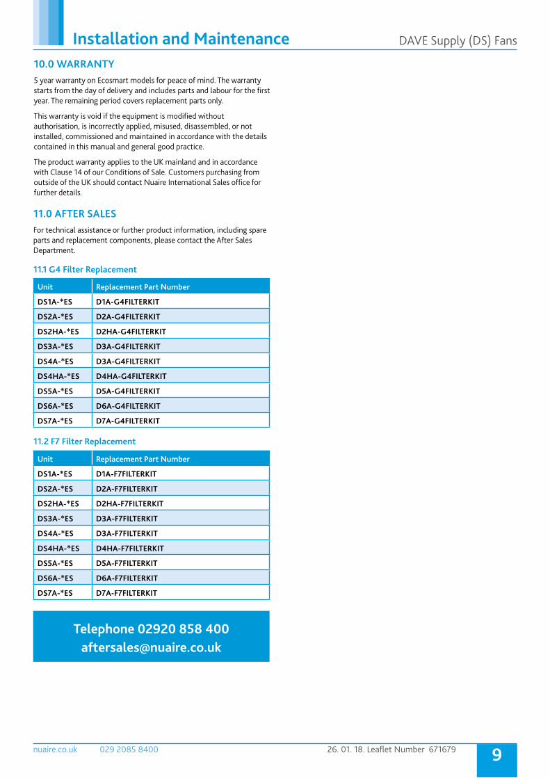
10.0 WARRANTY 5 year warranty on Ecosmart models for peace of mind. The warranty starts from the day of delivery and includes parts and labour for the first year. The remaining period covers replacement parts only.
This warranty is void if the equipment is modified without authorisation, is incorrectly applied, misused, disassembled, or not installed, commissioned and maintained in accordance with the details contained in this manual and general good practice.
The product warranty applies to the UK mainland and in accordance with Clause 14 of our Conditions of Sale. Customers purchasing from outside of the UK should contact Nuaire International Sales office for further details.
11.0 AFTER SALESFor technical assistance or further product information, including spare parts and replacement components, please contact the After Sales Department.
Telephone 02920 858 400 [email protected]
Unit Replacement Part Number
DS1A-*ES D1A-G4FILTERKIT
DS2A-*ES D2A-G4FILTERKIT
DS2HA-*ES D2HA-G4FILTERKIT
DS3A-*ES D3A-G4FILTERKIT
DS4A-*ES D3A-G4FILTERKIT
DS4HA-*ES D4HA-G4FILTERKIT
DS5A-*ES D5A-G4FILTERKIT
DS6A-*ES D6A-G4FILTERKIT
DS7A-*ES D7A-G4FILTERKIT
Unit Replacement Part Number
DS1A-*ES D1A-F7FILTERKIT
DS2A-*ES D2A-F7FILTERKIT
DS2HA-*ES D2HA-F7FILTERKIT
DS3A-*ES D3A-F7FILTERKIT
DS4A-*ES D3A-F7FILTERKIT
DS4HA-*ES D4HA-F7FILTERKIT
DS5A-*ES D5A-F7FILTERKIT
DS6A-*ES D6A-F7FILTERKIT
DS7A-*ES D7A-F7FILTERKIT
11.1 G4 Filter Replacement
11.2 F7 Filter Replacement

10nuaire.co.uk 029 2085 8400 26. 01. 18. Leaflet Number 671679
DECLARATION OF INCORPORATION AND INFORMATION FOR SAFE INSTALLATION, OPERATION AND MAINTENANCE
INFORMATION FOR SAFE INSTALLATION, OPERATION AND MAINTENANCEOF NUAIRE VENTILATION EQUIPMENT
We declare that the machinery named below is intended to be assembled withother components to constitute a system of machinery. All partsexcept for moving parts requiring the correct installation of safety guards complywith the essential requirements of the Machinery Directive. Themachinery shall not be put into service until the system has beendeclared to be in conformity with the provisions of the EC MachineryDirective.
Designation of machinery: DAVE Ecosmart (ES) models
Machinery Types: Supply fans
Relevant EC Council Directives: 20006/42/EC (Machinery Directive)
Applied Harmonised Standards: BS EN ISO 12100, BS EN ISO 13857 EN60204-1, BS EN ISO 9001
Applied National Standards: BS848 Parts 1, 2.2 and 5
Signature of manufacture representatives:Name: Position: Date:
1)C. Biggs Technical Director 28. 01. 15
2)A. Jones Manufacturing Director 28. 01. 15
To comply with EC Council Directives 2006/42/EC Machinery Directive and 2014/30/EU (EMC).To be read in conjunction with the relevant product documentation (see 2.1)
1.0 GENERAL
1.1 The equipment referred to in this Declaration of Incorporation is supplied by Nuaire to be assembled into a ventilation system which may or may not include additional components. The entire system must be considered for safety purposes and it is the responsibility of the installer to ensure that all of the equipment is installed in compliance with the manufacturers recommendations and with due regard to current legislation and codes of practice.
2.0 INFORMATION SUPPLIED WITH THE EQUIPMENT
2.1 Each item of equipment is supplied with a set of documentation which provides the information required for the safe installation and maintenance of the equipment. This may be in the form of a Data sheet and/or Installation and Maintenance instruction.2.2 Each unit has a rating plate attached to its outer casing. The rating plate provides essential data relating to the equipment such as serial number, unit code and electrical data. Any further data that may be required will be found in the documentation. If any item is unclear or more information is required, contact Nuaire.2.3 Where warning labels or notices are attached to the unit the instructions given must be adhered to.
3.0 TRANSPORTATION, HANDLING AND STORAGE
3.1 Care must be taken at all times to prevent damage to the equipment. Note that shock to the unit may result in the balance of the impeller being affected.3.2 When handling the equipment, care should be taken with corners and edges and that the weight distribution within the unit is considered. Lifting gear such as slings or ropes must be arranged so as not to bear on the casing.3.3 Equipment stored on site prior to installation should be protected from the weather and steps taken to prevent ingress of contaminants.
4.0 OPERATIONAL LIMITS
4.1 It is important that the specified operational limits for the equipment are adhered to e.g. operational air temperature, air borne contaminants and unit orientation.4.2 Where installation accessories are supplied with the specified equipment eg. wall mounting brackets. They are to be used to support the equipment only. Other system components must have separate provision for support.4.3 Flanges and connection spigots are provided for the purpose of joining to duct work systems. They must not be used to support the ductwork.4.4 Local Environment - Humidity. Ambient humidity (the humidity at the unit’s installed location) shall be within the range: 10 to 95% (for controls, non-condensing). Air humidity (the humidity of the air passing through the unit) shall be within the range: 10 to 95% (for controls, non-condensing).
5.0 INSTALLATION REQUIREMENTS
In addition to the particular requirements given for the individual product, the following general requirements should be noted.5.1 Where access to any part of equipment which moves, or can become electrically live are not prevented by the equipment panels or by fixed installation detail (e.g. ducting), then guarding to the appropriate standard must be fitted.5.2 The electrical installation of the equipment must comply with the requirements of the relevant local electrical safety regulations.5.3 For EMC all control and sensor cables should not be placed within 50mm or on the same metal cable tray as 230V switched live, lighting or power cables and any cables not intended for use with this product.
6.0 COMMISSIONING REQUIREMENTS
6.1 General pre-commissioning checks relevant to safe operation consist of the following: Ensure that no foreign bodies are present within the fan or casing. Check electrical safety. e.g. Insulation and earthing. Check guarding of system. Check operation of Isolators/Controls. Check fastenings for security.6.2 Other commissioning requirements are given in the relevant product documentation.
7.0 OPERATIONAL REQUIREMENTS
7.1 Equipment access panels must be in place at all times during operation of the unit, and must be secured with the original fastenings.7.2 If failure of the equipment occurs or is suspected then it should be taken out of service until a competent person can effect repair or examination. (Note that certain ranges of equipment are designed to detect and compensate for fan failure).
8.0 MAINTENANCE REQUIREMENTS
8.1 Specific maintenance requirements are given in the relevant product documentation.8.2 It is important that the correct tools are used for the various tasks required.8.3 If the access panels are to be removed for any reason the electrical supply to the unit must be isolated.8.4 A minimum period of two minutes should be allowed after electrical disconnection before access panels are removed. This will allow the impeller to come to rest. NB: Care should still be taken however since airflow generated at some other point in the system can cause the impeller to “windmill” even when power is not present.8.5 Care should be taken when removing and storing access panels in windy conditions.
Note: All standards used were current and valid at the date of signature.
Technical or commercial considerations may, from time to time, make it necessary to alter the design, performance and dimensions of equipment and the right is reserved to make such changes without prior notice.