Embed Size (px)
Citation preview

1 Description
I/O extension module, 4 analog current inputs
RAD-AI4-IFS
© PHOENIX CONTACT
Data sheet
INTERFACE
The RAD-AI4-IFS I/O extension module can be used in con-
junction with Radioline wireless modules and other Interface
System (IFS) master devices. In a station structure, you can
connect up to 32 I/O extension modules to a wireless module
via the DIN rail connector.
The RAD-AI4-IFS analog I/O extension module is used for
processing four input signals.
Features
– Easy and tool-free I/O mapping via thumb wheel on the
front
– Modular design via TBUS DIN rail connector (hot-swap
capable)
– Channel-to-channel electrical isolation
– 4 analog inputs (alternatively 0/4 20 mA)
– 16-bit resolution of the analog inputs (accuracy < 0.02%)
– Loop-power function for passive sensors
– International approvals
– Installation in Ex-Zone 2
WARNING: Correct usage in potentially explosive areas
The module is a category 3 item of electrical equipment. Follow the instructions provided here during installa-
tion and observe the safety instructions.
Make sure you always use the latest documentation.
It can be downloaded from the product at www.phoenixcontact.net/products.
This data sheet is valid for all products listed on the following page:
104839_en_01 2013-01-21

RAD-AI4-IFS
104839_en_01 PHOENIX CONTACT 2
2 Table of contents
1 Description .............................................................................................................................. 1
2 Table of contents ..................................................................................................................... 2
3 Ordering data .......................................................................................................................... 3
4 Technical data ......................................................................................................................... 3
5 Safety regulations and installation notes.................................................................................. 6
5.1 Installation and operation....................................................................................................... 6
5.2 Safety regulations for installation in potentially explosive areas ....................................................... 7
6 Installation ............................................................................................................................... 8
6.1 Structure ........................................................................................................................... 8
6.2 Basic circuit diagram ............................................................................................................ 8
6.3 Configuration...................................................................................................................... 9
6.4 Display and diagnostic elements ........................................................................................... 10
6.5 Analog input ..................................................................................................................... 10
6.6 Assembly/removal ............................................................................................................. 11
6.7 Connecting the cables ........................................................................................................ 11
7 Process data.......................................................................................................................... 12

RAD-AI4-IFS
104839_en_01 PHOENIX CONTACT 3
Description Type Order No. Pcs. / Pkt.
Analog expansion module with 4 analog current inputs (0/4 mA ... 20 mA),
with screw connection, incl. DIN rail connector
RAD-AI4-IFS 2901537 1
3 Ordering data
Accessories Type Order No. Pcs. / Pkt.
2400 MHz wireless transceiver with RS-232, RS-485 2-wire interface,
expandable with I/O extension modules, with screw connection, antenna
connection: RSMA (female), including DIN rail connector
RAD-2400-IFS 2901541 1
Bidirectional, Radioline 900 MHz transceiver for wireless transmission of
serial and I/O data
RAD-900-IFS 2901540 1
DIN rail connector for DIN rail power supply unit, gold-plated contacts,
for DIN rail mounting, 5-pos.
ME 17,5 TBUS 1,5/ 5-ST-3,81 GN 2709561 10
Analog I/O extension module with 4 analog current/voltage outputs
(0/4 mA ... 20 mA, 010 V), with screw connection, incl. DIN rail connector
RAD-AO4-IFS 2901538 1
4 Technical data
Dimensions (nominal sizes in mm)
Dimensions W / H / D 17.5 mm / 99 mm / 114.5 mm
17,599
11
4,5
General data
Surge voltage category II
Mounting position Any , on standard DIN rail NS 35 in accordance with EN 60715
Degree of protection IP20
Pollution degree 2
Type of housing PA 6.6-FR , green
Inflammability class according to UL 94 V0
Supply
Supply voltage range 19.2 V DC ... 30.5 V DC (T-connector)
Max. current consumption max. 120 mA (At 24 V DC, at 25°C)
Transient surge protection Yes

RAD-AI4-IFS
104839_en_01 PHOENIX CONTACT 4
Analog input
Number of inputs 4
Current input signal 0 mA ... 20 mA (can be set via DIP switches)
4 mA ... 20 mA (can be set via DIP switches)
Max. current input signal 22 mA
Input resistance current input < 70 Ω
Input frequency Approx. 30 Hz
Precision ≤ 0.02 % (@25°C)
Temperature coefficient, typical 0.0025 %/K (At -40°C...+70°C)
Supply voltage ≥ 12 V DC (For passive sensors (via terminal PWR1, +I1))
Resolution (bit) 16 (Bit)
Protective circuit Overload protection, short-circuit protection
Electrical isolation
Analog I/O 50 V (Rated insulation voltage (in each case between the TBUS analog outputs /
supply, reinforced insulation according to EN 61010, EN 50178))
Test voltage
Analog I/O 1.5 kV AC (50 Hz, 1 min.)
Connection data
Connection method Screw connection
Conductor cross section, solid 0.2 mm² ... 2.5 mm²
Conductor cross section, stranded 0.2 mm² ... 2.5 mm²
Conductor cross section AWG/kcmil 24 ... 14
Stripping length 7 mm
Tightening torque 0.6 Nm
Status indication
Status display Green LED (supply voltage, PWR)
Green LED (bus communication, DAT)
Red LED (periphery error, ERR)
Ambient conditions
Ambient temperature (operation) -40 °C ... 70 °C (>55°C Derating)
-40 °F ... 158 °F (>131°F derating)
Ambient temperature (storage/transport) -40 °C ... 85 °C
-40 °F ... 185 °F
Permissible humidity (operation) 20 % ... 85 %
Permissible humidity (storage/transport) 20 % ... 85 %
Altitude 2000 m
Vibration (operation) In accordance with IEC 60068-2-6: 5 g, 10 Hz - 150 Hz
Shock 16 g, 11 ms
Operating conditions for the extended temperature range (+55°C ... 70°C)
No function restrictions for the extended temperature range if you keep a minimum distance of 17.5 mm between the modules. The minimum
distance is the width of a DIN rail connector.
Otherwise please observe the following restrictions:
- Make sure that no more than 40 mA in total is drawn from the loop-powered PWR1 ... PWR4 outputs.
Individual operating conditions on request.

RAD-AI4-IFS
104839_en_01 PHOENIX CONTACT 5
Certification
Conformance CE-compliant
ATEX II 3 G Ex nA IIC T4 Gc X
IECEx Applied for
UL, USA / Canada UL applied for
Conformance
EMC directive 2004/108/EC EN 61000-6-2; EN 61000-6-4
Ex directive (ATEX) EN 60079-0; EN 60079-15
Tolerances influenced by electromagnetic interference
Type of electromagnetic interference Typical deviation of the measuring range final value (cur-
rent input)
- Relative Absolute
Electromagnetic fields according to EN 61000-4-3/IEC 61000-4-3 < ±0.2% ±40 µA
Conducted interference according to EN 61000-4-6/IEC 61000-4-6 < ±0.35% ±70 µA
Fast transients (burst) according to EN 61000-4-4/IEC 61000-4-4 < ±0.2% ±40 µA

RAD-AI4-IFS
104839_en_01 PHOENIX CONTACT 6
5 Safety regulations and installation
notes
5.1 Installation and operation
Follow the installation instructions.
Error-free operation of this device can only be ensured if
transport, storage, and assembly are carried out correctly and
operation and maintenance are carried out with care.
When installing and operating the device, the applicable sa-
fety directives (including national safety directives), accident
prevention regulations, as well as general technical regulati-
ons, must be observed.
Provide a switch/circuit breaker close to the device, which is
labeled as the disconnect device for this device.
Provide overcurrent protection (I ≤ 6 A) in the installation.
For the safety data, please refer to the operating instructions
and certificates (EC-type examination certificate, other appro-
vals, if necessary).
NOTE: Installation, operation, and mainte-
nance may only be carried out by qualified spe-
cialist personnel.
WARNING: Risk of electric shock
During operation, certain parts of this device
may carry hazardous voltages. Disregarding
this warning may result in damage to equip-
ment and/or serious personal injury.
For applications with high operating voltages,
ensure sufficient distance or insulation and pro-
vide shock protection.
NOTE: Access to circuits within the device is
not permitted.
Do not repair the device yourself but replace it
with an equivalent device.
Repairs may only be carried out by the manu-
facturer. The manufacturer is not liable for da-
mage resulting from a failure to comply.
During maintenance work, disconnect the de-
vice from all effective power sources.
NOTE: The IP20 degree of protection
(IEC 60529/EN 60529) of the device is inten-
ded for a clean and dry environment. Do not
subject the device to mechanical and/or ther-
mal loads that exceed the specified limits.

RAD-AI4-IFS
104839_en_01 PHOENIX CONTACT 7
5.2 Safety regulations for installation in potentially
explosive areas
Installation in zone 2
Installation in areas with a danger of dust explosions
WARNING: Explosion hazard
The device is designed for installation in zone 2
potentially explosive areas according to directi-
ve 94/9/EC. Observe the specified conditions
for use in potentially explosive areas.
WARNING: Explosion hazard
Install the device into a housing (control or dis-
tributor box) that meets the requirements of
EN 60079-0 and EN 60079-15 and has at least
IP54 protection (EN 60529).
WARNING: Explosion hazard
When installing and connecting the supply and
signal circuits observe the requirements of
EN 60079-14. Only devices suitable for opera-
tion in Ex zone 2 and the conditions at the ap-
plication site may be connected to the circuits
in zone 2.
WARNING: Explosion hazard
In potentially explosive areas, only connect and
disconnect cables when the power is discon-
nected.
Installation/removal of the devices on/from the
TBUS DIN rail connector may only be perfor-
med when no voltage is applied.
WARNING: Explosion hazard
Only use category 3G devices
(ATEX 94/9/EC).
WARNING: Explosion hazard
The device must be stopped and immediately
removed from the Ex area if it is damaged or
was subject to an impermissible load or stored
incorrectly or if it malfunctions.
WARNING: Explosion hazard
The device has not been designed for use in
potentially dust-explosive atmospheres.
RAD-AI4-IFS
104839_en_01 PHOENIX CONTACT 8
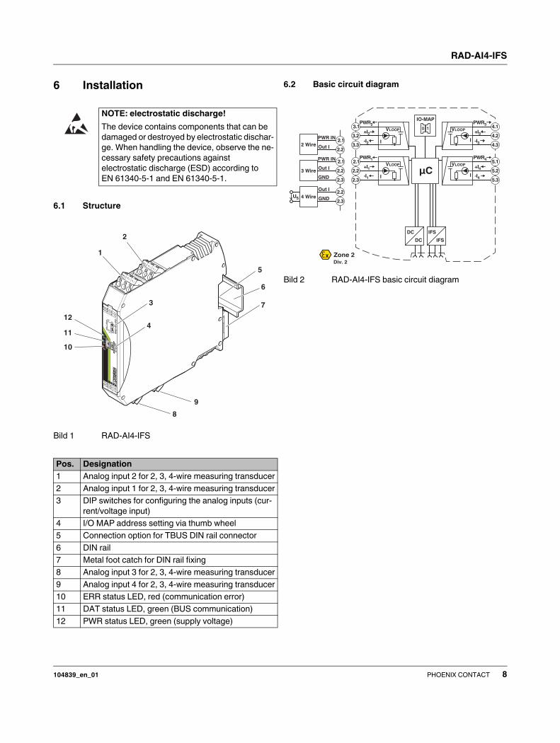
6 Installation
6.1 Structure
Bild 1 RAD-AI4-IFS
6.2 Basic circuit diagram
Bild 2 RAD-AI4-IFS basic circuit diagram
NOTE: electrostatic discharge!
The device contains components that can be
damaged or destroyed by electrostatic dischar-
ge. When handling the device, observe the ne-
cessary safety precautions against
electrostatic discharge (ESD) according to
EN 61340-5-1 and EN 61340-5-1.
Pos. Designation
1 Analog input 2 for 2, 3, 4-wire measuring transducer
2 Analog input 1 for 2, 3, 4-wire measuring transducer
3 DIP switches for configuring the analog inputs (cur-
rent/voltage input)
4 I/O MAP address setting via thumb wheel
5 Connection option for TBUS DIN rail connector
6 DIN rail
7 Metal foot catch for DIN rail fixing
8 Analog input 3 for 2, 3, 4-wire measuring transducer
9 Analog input 4 for 2, 3, 4-wire measuring transducer
10 ERR status LED, red (communication error)
11 DAT status LED, green (BUS communication)
12 PWR status LED, green (supply voltage)
IO-M
AP
RA
D-A
I4-I
FS
PWR
DAT
ERR
1
2
3
4
OFF
ON
DIP-1
88
Pwr1Pwr2
+I1
+I2
-I1
-I2
Pwr3Pwr4
+I3
+I4
-I3
-I4
Pwr1
Pwr2
+I1
+I2
-I1
-I2
1
2
3
4
5
7
9
12
11
10
8
6
3 Wire
PWR IN
Out
GND
2.1
2.2
2.3
2 Wire
PWR IN
Out
2.1
2.2
4 Wire
Out
GNDUS
2.2
2.3
Zone 2Div. 2
IO-MAP
µC
DC
DC
IFS
IFS
3.1
3.2
3.3I
VLOOP
PWR2
+I2
-I2
4.1
4.2
4.3
VLOOP
PWR3
+I3
-I3I
2.1
2.2
2.3
VLOOP
PWR1
+I1
-I1 I
5.1
5.2
5.3
VLOOP
PWR4
+I4
-I4I

RAD-AI4-IFS
104839_en_01 PHOENIX CONTACT 9
6.3 Configuration
The DIP switches on the front can be used to configure the
input signals ranges (0 20 mA or 4 20 mA).
Bild 3 DIP switches
I/O MAP address
Bild 4 Thumb wheel
Use the thumb wheel to set the I/O MAP address. The
address is used to address the I/O module for use in the Ra-
dioline wireless system.
The following conditions must be met:
On the entire wireless network, addresses 1 to 99 (I/O MAP)
(maximum) may be assigned for the I/O extension modules.
Wireless module in I/O data mode (wire in/wire out)
The input device must be provided with the same I/O MAP
address as the assigned output device at the other wireless
station (I/O mapping).
The I/O MAP address of an input module may only appear
once in the network.
Only the RAD-AO4-IFS module can be assigned to the
RAD-AI4-IFS module.
DIP switch
Input Configuration 1 2 3 4
Analog IN1 020 mA off
Analog IN1 420 mA on
Analog IN2 020 mA off
Analog IN2 420 mA on
Analog IN3 020 mA off
Analog IN3 420 mA on
Analog IN4 020 mA off
Analog IN4 420 mA on
-I4+I4PWR4
-I3+I3PWR3
-I2+I2PWR2
-I1+I1PWR1
OFF ON
DIP-1
1234
PWR
DAT
ERR
44
3WR3
22
1WR1
Thumb wheel
settings
Description
01 - 99 I/O MAP address
00 Delivery state
**, 1* - 9* Setting not permitted
1* - 9* Interface System slave address, for use
with Interface System (IFS) master devices
Example: I/O MAP address
RAD-AI4-IFS 02
RAD-AO4-IFS 02
-I4+I4PWR4
-I3+I3PWR3
-I2+I2PWR2
-I1+I1PWR1
OFF ON
DIP-1
1234
PWR
DAT
ERR
44
3WR3
22
1WR1

RAD-AI4-IFS
104839_en_01 PHOENIX CONTACT 10
Wireless module in PLC/Modbus RTU mode
The I/O MAP address of an input module may only appear
once in the network.
The input data is saved in a Modbus memory map in the mas-
ter wireless module.
You can read or write the process data via the serial interface
of the RAD-2400-IFS master wireless module (RAD-ID = 01)
using the Modbus RTU command (see Section 7).
6.4 Display and diagnostic elements
3 LEDs on the RAD-AI4-IFS I/O extension module in total in-
dicate the operating states.
Bild 5 Display and diagnostic elements
6.5 Analog input
The analog input of the extension module is able to process
standard signals (0/420 mA).
All the inputs are electrically isolated from one another, from
the supply voltage (via bus foot), and from other electronic
components.
A supply voltage of 12 V DC, minimum, is available at the con-
nection terminal block (PWR1) for the use of passive sensors
(1 in Figure 1, connection assignment see Figure 2).
PWR LED
The green PWR LED indicates the supply voltage status.
Off: No supply voltage
On: Supply voltage OK
DAT LED
The green DAT LED indicates the bus communication sta-
tus.
Off: No communication
Flashing: Configuration/addressing mode
On: Cyclic data communication
-I4+I4PWR4
-I3+I3PWR3
-I2+I2PWR2
-I1+I1PWR1
OFF ON
DIP-1
1234
PWR
DAT
ERR
44
3WR3
22
1WR1
ERR LED
The red ERR LED indicates the error status, e.g., no corres-
ponding output module found (e.g., incorrect addressing).
Off: No error
Flashing: Slow
(1.4 Hz)
I/O-MAP address changed
Fast
(2.8 Hz)
No bus communication
On: Critical internal error

RAD-AI4-IFS
104839_en_01 PHOENIX CONTACT 11
6.6 Assembly/removal
Bild 6 Mounting and removing
• When using the DIN rail connector, first insert it in the
35 mm DIN rail according to EN 60715
(see Figure 6, A - C).
The DIN rail connector is used to bridge the power supply
and communication.
• Install the module in a suitable housing to meet the requi-
rements for the protection class.
• Before startup, check that the RAD-AI4-IFS is operating
and wired correctly, in particular with regard to the wiring
and labeling.
• You can establish a connection between two DIN rail con-
nectors using MINI COMBICON plug-in connectors:
MC 1,5/5-ST-3,81 (female, 1803604);
IMC 1,5/5-ST-3,81 (male, 1857919).
6.7 Connecting the cables
Bild 7 Connection of the cables
• Crimp ferrules to the wires.
Permissible cable cross section: 0.2...2.5 mm².
• Insert the wire with ferrule into the corresponding connec-
tion terminal block.
• Use a screwdriver to tighten the screw in the opening
above the connection terminal block.
Tightening torque: 0.6 Nm
The use of the TBUS DIN rail connector for the
supply of modules is only possible with
24 V DC devices.
In this case, it is vital to observe the mounting
direction of the module and DIN rail connector:
snap-on foot at the bottom and connector on
the left.
The maximum cable length is 10 m.
Use shielded cables.
A B C
D E
A
B8
8PW
R
DAT
ERR

RAD-AI4-IFS
104839_en_01 PHOENIX CONTACT 12
7 Process data
You can read the process data via the serial interface of the
RAD-2400-IFS master wireless module (RAD-ID = 01) using
the Modbus RTU command.
With the PSI-CONF software, you can set the wireless mo-
dule's network application to “PLC/Modbus RTU mode”.
The process image of the I/O module consists of ten data
words of which six are being used.
xx = I/O-MAP address set using the thumbwheel
The read I/O data is only valid if a valid module type value is
returned by the slave and if bit 8 is not set.
I/O module RAD-AI4-IFS
Module type 20hex
Number of registers 06hex
Address space 30xx0-30xx5
Modbus function code fc04
30xx0 Module type and currentness of data
Byte Byte 0 (high byte)
Bit 15 14 13 12 11 10 09 08
Module type
Currentness of
data
X
Byte Byte 1 (low byte)
Bit 07 06 05 04 03 02 01 00
Module type 0 0 1 0 0 0 0 0
Currentness of
data
Register values:
Module type If the module type in the register is invalid
or unavailable, then the register value is 0
Currentness of
data
If the data in the register is not up-to-date,
then the register value is 1.
This is the case if, for example, the wirel-
ess connection fails.
The IN process data is retained in the Mod-
bus table, but is no longer updated.
30xx1 Reserved
30xx2 Analog input 1
Byte Byte 0 (high byte)
Bit 15 14 13 12 11 10 09 08
Channel AI1 AI1 AI1 AI1 AI1 AI1 AI1 AI1
Terminal point
Byte Byte 1 (low byte)
Bit 07 06 05 04 03 02 01 00
Channel AI1 AI1 AI1 AI1 AI1 AI1 AI1 AI1
Terminal point 2.x
30xx3 Analog input 2
Byte Byte 0 (high byte)
Bit 15 14 13 12 11 10 09 08
Channel AI2 AI2 AI2 AI2 AI2 AI2 AI2 AI2
Terminal point
Byte Byte 1 (low byte)
Bit 07 06 05 04 03 02 01 00
Channel AI2 AI2 AI2 AI2 AI2 AI2 AI2 AI2
Terminal point 3.x
30xx4 Analog input 3
Byte Byte 0 (high byte)
Bit 15 14 13 12 11 10 09 08
Channel AI3 AI3 AI3 AI3 AI3 AI3 AI3 AI3
Terminal point
Byte Byte 1 (low byte)
Bit 07 06 05 04 03 02 01 00
Channel AI3 AI3 AI3 AI3 AI3 AI3 AI3 AI3
Terminal point 4.x
30xx5 Analog input 4
Byte Byte 0 (high byte)
Bit 15 14 13 12 11 10 09 08
Channel AI4 AI4 AI4 AI4 AI4 AI4 AI4 AI4
Terminal point
Byte Byte 1 (low byte)
Bit 07 06 05 04 03 02 01 00
Channel AI4 AI4 AI4 AI4 AI4 AI4 AI4 AI4
Terminal point 5.x
30xx6 ... 30xx9 Reserved

RAD-AI4-IFS
104839_en_01 13PHOENIX CONTACT GmbH & Co. KG • 32823 Blomberg • Germany
www.phoenixcontact.com
Illustration of analog values
Data word 0 ... 20 mA 4 ... 20 mA
hex dec
0000 0 0 mA -
1770 6000 4 mA 4 mA
7530 30000 20 mA 20 mA
8001 Overrange
(>32505) > 21,67 > 21,67
8002 Open circuit
(<4800) - <3,2 mA
8080 Underrange (<-15) < 0 mA -