Embed Size (px)
Citation preview
(12) INTERNATIONAL APPLICATION PUBLISHED UNDER THE PATENT COOPERATION TREATY (PCT)(19) World Intellectual Property
OrganizationInternational Bureau
(43) International Publication Date22 October 2015 (22.10.2015) WIPO I PCT
llIIlIIlllIlIlllIlIllIllIllIIlIlllIIlIlllllllIlllIIlIllIllIllllIIIlllIIlllIlIIIIIIIIIIIIIIIIIII
(10) International Publication Number
WO 2015/158711 A1
(51) International Patent Classification:C25B 1/00 (2006.01)
(21) International Application Number
(22) International Filing Date:
PCT/EP2015/058072
(25) Filing Language:
(26) Publication Language:
14 April 2015 (14.04.2015)
English
English
(30) Priority Data:14165214.9 17 April 2014 (17.04.2014) EP
(71) Applicants: BASF SE [DE/DE]; 67056 Ludwigshafen
(DE). MAX-PLANCK-GESELLSCHAFT ZUR FOR-DERUNG DER WISSENSCHAFTEN E.V. [DE/DE];Hofgartenstrasse 8, 80539 Munich (DE).
(72) Inventors: VENKATARAMAN, Shyam Sundar; Van-Leyden-Str. 28, 67061 Ludwigshafen (DE). KURKINA,Tetiana; Branchweilerhofstr. 53, 67433 Neustadt (DE).NATHAN-WALLESER, Teressa; St. Ulrichstr. 31,79189 Bad Krozingen (DE). PARVEZ, Khaled; Hecht-sheimer Str. 37a, 55131 Mainz (DE). FENG, Xinliang;Thomas-Mann-Str. 11, 55122 Mainz (DE). MULLEN,Klaus; Geisbergstr. 139, 50939 Koln (DE).
(74) Agent: MAIWALD PATENTANWALTS GMBH; Elis-enstr. 3 / Elisenhof, Munich 80335 (DE).
(Sl) Designated States (unless otherwise indicated, for everykind of national protection available): AE, AG, AL, AM,AO, AT, AU, AZ, BA, BB, BG, BH, BN, BR, BW, BY,BZ, CA, CH, CL, CN, CO, CR, CU, CZ, DE, DK, DM,DO, DZ, EC, EE, EG, ES, FI, GB, GD, GE, GH, GM, GT,HN, HR, HU, ID, IL, IN, IR, IS, JP, KE, KG, KN, KP, KR,KZ, LA, LC, LK, LR, LS, LU, LY, MA, MD, ME, MG,MK, MN, MW, MX, MY, MZ, NA, NG, NI, NO, NZ, OM,PA, PE, PG, PH, PL, PT, QA, RO, RS, RU, RW, SA, SC,SD, SE, SG, SK, SL, SM, ST, SV, SY, TH, TJ, TM, TN,TR, TT, TZ, UA, UG, US, UZ, VC, VN, ZA, ZM, ZW.
(S4) Designated States (unless otherwise indicated, for everykind of regional protection available): ARIPO (BW, GH,GM, KE, LR, LS, MW, MZ, NA, RW, SD, SL, ST, SZ,TZ, UG, ZM, ZW), Eurasian (AM, AZ, BY, KG, KZ, RU,TJ, TM), European (AL, AT, BE, BG, CH, CY, CZ, DE,DK, EE, ES, FI, FR, GB, GR, HR, HU, IE, IS, IT, LT, LU,LV, MC, MK, MT, NL, NO, PL, PT, RO, RS, SE, SI, SK,SM, TR), OAPI (BF, BJ, CF, CG, CI, CM, GA, GN, GQ,GW, KM, ML, MR, NE, SN, TD, TG).
Published:
with international search report (Art. 2/(3))
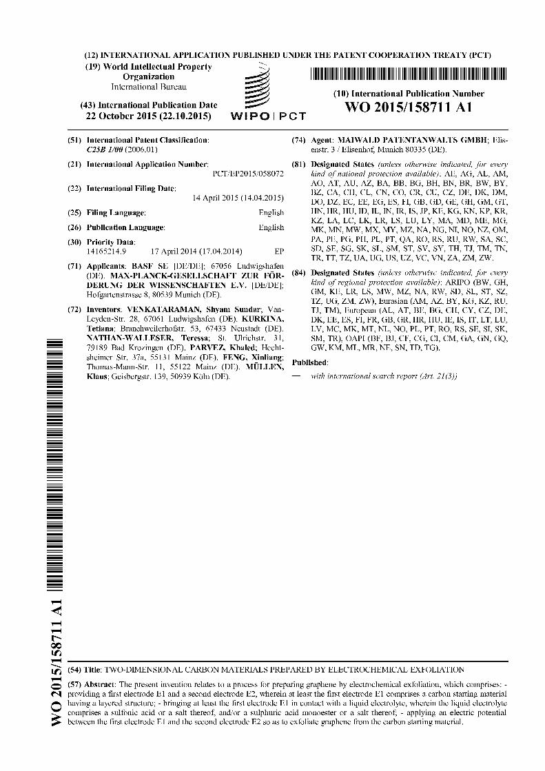
(54) Title: TWO-DIMENSIONAL CARBON MATERIALS PREPARED BY ELECTROCHEMICAL EXFOLIATION
(57) Abstract: The present invention relates to a process for preparing graphene by electrochemical exfoliation, which comprises:-providing a first electrode El and a second electrode E2, wherein at least the first electrode El comprises a carbon starting material
0 having a layered structure; - bringing at least the first electrode El in contact with a liquid electrolyte, wherein the liquid electrolytecomprises a sulfonic acid or a salt thereof, and/or a sulphuric acid monoester or a salt thereof; - applying an electric potentialbetween the first electrode El and the second electrode E2 so as to exfoliate graphene from the carbon starting material.
WO 2015/158711 PC T/EP2015/058072
Two-dimensional carbon materials prepared by electrochemical exfoliation
The present invention relates to electrochemically exfoliated graphene and its use for
manufacturing electronic, optoelectronic, energy-storing or energy-transforming devices.
10
Graphene, a two-dimensional (2D) honeycomb sp' carbon lattice, has received extensive
attention due to its unique chemical, mechanical and electrical properties. These properties
make it a promising material for next-generation nanoelectronics, composite materials, sensors,
batteries, electrochemical capacitors etc. However, the large-scale production of high quality,
solution processable graphene via a simple low-cost method remains a major challenge.
15
20
25
30
Several methods have been developed to produce graphene since its discovery. Among them,
mechanically exfoliated and epitaxially grown graphene exhibit high quality but only produce a
limited quantity of materials for fundamental research. Chemical vapor deposition (CVD)
methods using catalytic metal substrates such as Ni or Cu, has the capability to produce large
area graphene. These preparation methods are described e.g. in Science 306, 666-669 (2004).However, requirements of high temperature, a sacrificial metal and multi-step transfer
processes onto desired substrates, are the biggest obstacles for cost effective industrial-scale
production of CVD grown graphene.
Chemical exfoliation of graphite based on Hummers method provides an alternative to produce
solution dispersible graphene oxide (GO) and is described e.g. in Nat Nanotechno/3, 270-274
(2008). However, this method requires thermal or chemical reduction and electronic properties
can only be partially restored.
Other methods have been developed to overcome these limitations and to obtain high quality
graphene such as, solvent and/or surfactant assisted liquid-phase exfoliation (as described e.g.in Nat Nanotechno/3, 563-568 (2008)), electrochemical expansion (as described e.g. in JAm
Chem Soc 133, 8888-8891 (2011)), and formation of graphite intercalated compounds (asdescribed e.g. in Nat Nanotec/7no/6, 439-445 (2011)).Nevertheless, these methods require
extensive sonication which is limiting the size and yield of thin graphene layers.
35
Recently, electrochemical exfoliation of graphite has attracted attention as a simple and efficient
way to produce graphene.
Adv Funct Mater 18, 1518-1525 (2008) describes the preparation of graphene by
electrochemical exfoliation in an electrolyte containing ionic liquids.
40US 2013/0001089 describes the preparation of graphene by electrochemical exfoliation using a
carbon-based electrode and an aqueous electrolyte which may contain an acid such as H2SO4.
Optionally, a base such as KOH and NaOH can be added.
WO 2015/158711 PC T/EP2015/058072
It is an object of the present invention to prepare graphene by a process which is economically
efficient and provides high quality graphene which is suitable for preparing electronic,
optoelectronic or energy-storing or energy-transforming devices.
10
5 According to a first aspect of the present invention, the problem is solved by a process for
preparing graphene by electrochemical exfoliation, which comprises:
providing a first electrode E1 and a second electrode E2, wherein at least the first
electrode E1 comprises a carbon starting material having a layered structure;
bringing at least the first electrode E1 in contact with a liquid electrolyte, wherein the liquid
electrolyte comprises a salt which
is a salt of a sulfonic acid (in the following also referred to as a sulfonate salt) or a
salt of a sulphuric acid monoester (in the following also referred to as a monoester
sulphate salt), and
is an ionic liquid;
15 — applying an electric potential between the first electrode E1 and the second electrode E2
so as to exfoliate graphene from the carbon starting material.
20
25
In the present invention, it has been realized that graphene of low defect density can be
electrochemically exfoliated at high rate from a starting carbon material when using an
electrolyte which comprises an ionic liquid having a sulfonate or monoester sulphate anion. The
graphene prepared by the process shows high dispersion stability in suitable solvents.
Furthermore, electrochemical capacitors having electrodes made of the electrochemically
exfoliated graphene show surprisingly low RC time constants and are therefore suitable for high
frequency applications such as AC line filtering. Also the graphene from this process can be
used as a primer or a conductive layer to coat on current collectors such as Cu or Al for lithium
ion battery electrode fabrication.
The term "ionic liquid" is used according to its commonly accepted meaning and therefore
relates to a salt which has a low melting temperature, typically less than 100'C or even less
30 than 60'C. Ionic liquids having sulfonate anions or monoester sulphate anions are generally
known to the skilled person and commercially available or obtainable by standard preparation
methods. Accordingly, appropriate cations which form an ionic liquid with a sulfonate or
monoester sulphate anion are generally known to the skilled person. Exemplary cations will be
discussed below in further detail.
35The sulfonate salt according to the first aspect of the present invention can have the following
formula (II I)
WO 2015/158711 PC T/EP2015/058072
0
R S 0 [M"'])an
0
10
wherein
R is an organic residue, e.g. a substituted or unsubstituted alkyl group or a substituted or
unsubstituted aryl group, more preferably a substituted or unsubstituted C& 4 alkyl group,
and
M is a cation, and n is the valency of the cation (typically, n is 1, 2 or 3).
The monoester sulfate salt according to the first aspect of the present invention can have the
15 following formula (IV)
20
0
R —0 —S —0 [M"']as,
0
(IV)
25
wherein
R is an organic residue, e.g. a substituted or unsubstituted alkyl group or a substituted or
unsubstituted aryl group, more preferably a substituted or unsubstituted C& 4 alkyl group,
and
M is a cation, and n is the valency of the cation (typically, n is 1, 2 or 3).
30
35
According to a second aspect of the present invention, the problem is solved by a process for
preparing graphene by electrochemical exfoliation, which comprises:
providing a first electrode E1 and a second electrode E2, wherein at least the first
electrode E1 comprises a carbon starting material having a layered structure;
bringing at least the first electrode E1 in contact with a liquid electrolyte, wherein the liquid
electrolyte comprises a sulfonic acid of formula (I) or a salt thereof, and/or a sulphuric acid
monoester of formula (II) or a salt thereof:
WO 2015/158711 PC T/EP2015/058072
0
R —S —OH
0
100
R —0 —S —OH
0
15 wherein in each of the formulas (I) and (II)
R is methyl, ethyl, propyl, or butyl;
applying an electric potential between the first electrode E1 and the second electrode E2
so as to exfoliate graphene from the carbon starting material.
20
25
30
In the present invention, it has been realized that a layered carbon starting material (such as
graphite) can be electrochemically exfoliated at a very high rate if the electrolyte of the
electrochemical cell contains a lower alkyl sulfonic acid or a lower alkyl monoester of sulphuric
acid as defined above or a salt thereof. Furthermore, although exfoliated at high rate, the
graphene material has a high content of "1-3 layer graphene"; and graphene films prepared
therefrom have a low sheet resistance. Electrochemical capacitors having electrodes made of
the electrochemically exfoliated graphene show surprisingly low RC time constants and are
therefore suitable for high frequency applications such as AC line filtering. Also the graphene
from this process can be used as a primer or a conductive layer to coat on current collectors
such as Cu or Al for lithium ion battery electrode fabrication.
If the liquid electrolyte contains a salt of the sulfonic acid of formula (I) or a salt of the sulphuric
acid monoester of formula (II), any salt commonly known to the skilled person can be used.
Organic as well as inorganic cations can be used. Exemplary cations include ammonium
cations, alkali metal cations (e.g. Na', K'), alkaline earth metal cations (e.g. Mg", Ca", Sr",35 Ba"), and transition metal cations.
WO 2015/158711 PC T/EP2015/058072
The ammonium cation can have the following formula
R~
R"-N-R3
R4
wherein R", R', R' and R', independently from each other are hydrogen or C~ 4 alkyl.
It is also possible that the ammonium cation is derived from a polyamine, e.g. a diamine (such
10 as an ethylene diamine or a propylene diamine), by protonation and/or alkylation.
15
20
It is also possible that the salt of the sulfonic acid of formula (I) or the sulphuric acid monoester
of formula (II) is an ionic liquid. As already indicated above, in the present invention, the term
"ionic liquid" is used according to its commonly accepted meaning and therefore relates to a salt
which has a low melting temperature, typically less than 100'C or even less than 60'C. Ionic
liquids having sulfonate anions or monoester sulphate anions are generally known to the skilled
person and commercially available or obtainable by standard preparation methods. Accordingly,
appropriate cations which form an ionic liquid with a sulfonate or monoester sulphate anion are
generally known to the skilled person. Exemplary cations will be discussed below in further
detail.
Unless indicated otherwise, the following statements apply to the process according to the first
aspect and the second aspect of the present invention.
25 In the present application, the term "graphene" is not limited to a single layer graphene but also
encompasses a few-layer graphene having e.g. up to twenty graphene layers.
As indicated above, the first electrode E1 comprises a carbon starting material having a layered
structure. Appropriate carbon materials from which graphene can be exfoliated are commonly
30 known to the skilled person.
The carbon starting material having a layered structure can be e.g. a graphite, a chemically
modified graphite such as a graphite oxide, an intercalated graphite, or a mixture thereof.
35 The graphite can be a natural graphite or a synthetic graphite. Exemplary graphite materials
include a highly oriented pyrolytic graphite (HOPG), an expanded graphite, an intercalated
graphite, or any combination thereof. For avoiding a subsequent reduction treatment, it can be
preferred that the first electrode E1 does not contain a graphite oxide. It may also be preferred
that both the first electrode E1 and the second electrode E2 do not contain a graphite oxide.
40The carbon starting material, preferably graphite, can be provided in any form which is
consistent with its use as an electrode material, e.g. in the form of flakes, a powder, fibers, foils,
WO 2015/158711 PC T/EP2015/058072
rods, a paste, or any combination thereof. An exemplary graphite foil can be made of e.g.thermally expanded graphite pressed into thin sheets. As generally known, thermally expanded
graphite can be produced from natural graphite flakes via intercalation.
5 The electrode E1 can be e.g. a single graphite flake or many flakes held together. In the latter
case, the flakes can be placed on a conductive surface, physically pressed together or held
together using a binder such as a pyrolysed polymer (e.g. an extruded graphite rod).
Preferably, the carbon starting material having a layered structure is graphite in the form of a foil
10 or rod.
The electrode E2 can be made of any material commonly known as an electrode material. The
electrode E2 can be made of e.g. a metal such as Pt, Au, a conductive carbon material, ... etc.In principle, it is possible that the second electrode E2 also comprises a carbon material having
15 a layered structure such as graphite or modified graphite.
As indicated above, at least the first electrode E1 is brought into contact with a liquid electrolyte,
e.g. by immersing, either partly or completely, the electrode E1 in the liquid electrolyte.
20 Optionally, the second electrode E2 may also be brought into contact with the same liquid
electrolyte, e.g. by immersing, either partly or completely, the electrode E2 in the liquid
electrolyte. If so, both electrodes E1 and E2 are in contact with the same electrolyte.
Preferably, the liquid electrolyte is an aqueous electrolyte. In principle, the aqueous electrolyte
25 may additionally comprise a polar solvent such as an alcohol. However, it is preferred that water
represents the major part among the solvents being present in the electrolyte (e.g. more than 50vol% or more than 75 vol%, based on the total volume of the solvents being present in the
electrolyte).
30
35
If the electrolyte comprises a salt which is an ionic liquid, it is possible that at least 80 wt% or at
least 90 wt% of the liquid electrolyte are made of the ionic liquid. The liquid electrolyte may even
consist of the ionic liquid. The process is then operated at a temperature above the melting
temperature of the ionic liquid. However, in a preferred embodiment, the liquid electrolyte
contains one or more solvents, preferably water (i.e. an aqueous electrolyte), and the ionic
liquid is dissolved or dispersed in the solvent(s).
In principle, pH of the liquid (preferably aqueous) electrolyte can vary over a broad range. The
liquid electrolyte can be acidic, i.e. pH is less than 7 or less than 5 or even less than 3.Alternatively, the liquid electrolyte can be alkaline, i.e. pH is higher than 7 or higher than 8 or
40 even higher than 9. According to a further alternative, the liquid electrolyte can have a pH of 7+2
(i.e. 5 to 9) or 7+1 (i.e. 6 to 8).
WO 2015/158711 PC T/EP2015/058072
As already mentioned above, cations M which may form an ionic liquid together with a sulfonate
or monoester sulphate anion are generally known to the skilled person.
If the liquid electrolyte comprises a salt which is an ionic liquid, the cation M can be selected
5 from e.g. a heterocyclic cation, an ammonium cation, or a phosphonium cation.
The heterocyclic cation can be aromatic or non-aromatic. The one or more heteroatoms being
present in the ring of the heterocyclic cation can be e.g. nitrogen, oxygen, or sulphur.
10 Exemplary heterocyclic nitrogen-containing cations include e.g. an imidazolium cation, a
pyridinium cation, a pyrrolidinium cation, a pyrazolium cation, a pyridazinium cation, a
pyrimidinium cation, a pyrazinium cation, an oxazolium cation, a triazolium cation, a thiazolium
cation, a piperidinium cation, a quinolium cation, an isoquinolium cation, a benzimidazolium
cation.
15If the salt which is present in the liquid electrolyte is an imidazolium cation, it can have the
following formula:
R4 R'
NON
20
25
R3
wherein the residues R" to R' are, independently from each other, selected from hydrogen, a
substituted or unsubstituted Cl-12 alkyl group, a substituted or unsubstituted C& 6 alkoxy group,
or hydroxy. In case of a substituted alkyl or alkoxy group, one or more of the hydrogen atoms of
the alkyl or alkoxy group can be substituted e.g. by —OH or —CN.
In a preferred embodiment, R" is a Cl-12 alkyl, more preferably a C& 6 alkyl or a C& 4 alkyl, R' is a
C& 4 alkyl, more preferably a C& 2 alkyl, R' is hydrogen or a C& 2 alkyl, R' is hydrogen, and R' is
hydrogen.
35
30 The ammonium cation can have the following formula
R2
R"-N-R3
R4
wherein R", R', R' and R', independently from each other, are hydrogen or C~ 4 alkyl.
WO 2015/158711 PC T/EP2015/058072
It is also possible that the ammonium cation is derived from a polyamine, e.g. a diamine (such
as ethylene diamine or propylene diamine) or a triamine, by protonation and/or alkylation.
The concentration of the sulfonic acid of formula (I) or a salt thereof, or the sulphuric acid
5 monoester of formula (II) or a salt thereof according to the second aspect of the present
invention, and the salt according to the first aspect of the present invention in the liquid
electrolyte can vary over a broad range.
If a sulfonic acid of formula (I) or a salt thereof, which is not an ionic liquid, is present in the
10 liquid electrolyte, its concentration can be e.g. within the range of from 0.05 wt% to 20 wt%,
more preferably from 0.1 wt% to 10 wt% or from 0.5 wt% to 7 wt%.
If a sulphuric acid monoester of formula (II) or a salt thereof, which is not an ionic liquid, is
present in the liquid electrolyte, its concentration can be e.g. within the range of from 0.05 wt%
15 to 20 wt%, more preferably from 0.1 wt% to 10 wt% or from 0.5 wt% to 7 wt%.
If the liquid (preferably aqueous) electrolyte comprises a salt which is an ionic liquid, either
according to the first aspect or the second aspect of the present invention, the salt can be
present in a concentration of from 0.1 wt% to 80 wt%, more preferably 1.0 wt% to 50 wt%, even
20 more preferably 1.5 wt% to 35 wt%.
Alternatively, if an ionic liquid is used, the liquid electrolyte may even consist of the sulfonate or
monoester sulphate salt.
25 These concentration values may refer to the concentration at the beginning of the
electrochemical exfoliation process and may change during the process. It is also possible that
the concentration is within the ranges indicated above until completion of the electrochemical
exfoliation process, if necessary by adding further sulfonic acid of formula (I) or sulphuric acid
monoester of formula (II) or sulfonate or monoester sulphate salts during the process.
30The liquid (preferably aqueous) electrolyte can be obtained by at least partly dissolving the
sulfonic acid of formula (I) or the sulphuric acid monoester of formula (II) or the sulfonate or
monoester sulphate salt in a solvent, preferably in water. The liquid (preferably aqueous)
electrolyte can also be obtained by adding to a solvent, preferably water, the acid which
35 provides upon deprotonation the anion and a basic compound which provides upon protonation
the cation. The acid and the basic compound can be added simultaneously or one after the
other (e.g. the basic compound first and then the acid, or vice versa).
The liquid electrolyte may contain one or more additives such as a surfactant, a dispersant, an
40 oxidant, a buffering agent, or any mixture thereof. Alternatively, it is possible that the liquid
electrolyte does not contain one or more of these additives, e.g. does not contain a surfactant
and/or a dispersant.
WO 2015/158711 PC T/EP2015/058072
For further improving dispersion stability of the graphene in the liquid electrolyte, an aryl sulfonic
acid condensation product, more preferably a naphthalene sulfonic acid condensation product
can be present in the liquid electrolyte. If present, it is preferably a condensation product of an
5 aryl sulfonic acid, in particular a naphthalene sulfonic acid, or a salt thereof with an aldehyde, in
particular formaldehyde. Such condensation products are commercially available.
10
15
If present, one or more of these additives may already be added at the beginning of the
electrochemical exfoliation process or may alternatively be added at a later stage (i.e. when the
electrochemical exfoliation of graphene has already started or even after completion of the
electrochemical exfoliation of graphene). So, in principle, it is also possible in the process of the
present invention that the liquid electrolyte does not contain a dispersant and/or a surfactant
when the electrochemical exfoliation process is started, and a dispersant and/or a surfactant
is/are added to the liquid electrolyte during the electrochemical exfoliation of graphene and/or
after completion of the electrochemical exfoliation of graphene (e.g. for stabilizing the exfoliated
graphene layers).
20
If present, the surfactant can be a non-ionic, an anionic or a cationic surfactant. Appropriate
dispersants are commonly known to the skilled person.
As indicated above, an electric potential is applied between the first electrode E1 and the
second electrode E2 so as to exfoliate the graphene from the carbon starting material.
Based on common general knowledge, the skilled person is able to select an electric potential
25 which is high enough for initiating exfoliation and thereby separating graphene layers from the
carbon starting material.
Whether or not exfoliation has been initiated can be verified e.g. by detecting morphological
changes in the electrode E1 and/or detecting graphene which has been exfoliated from the
30 electrode E1 into the liquid electrolyte.
35
The electric potential applied between the first electrode E1 and the second electrode E2 can
vary over a broad range and is typically in the range of from 0.01 V to 200 V, more preferably
0 05 V to 20 V or 0.1 V to 15 V.
In principle, any power or voltage source commonly known to the skilled person can be used for
applying the electric potential between the electrodes E1 and E2.
Preferably, the electric potential is high enough for at least temporarily generating a gas at the
40 electrode E1 and/or the electrode E2. Whether or not a gas is generated at an electrode can
easily be detected (e.g. formation of gas bubbles at the electrode surface).
WO 2015/158711
10PC T/EP2015/058072
It can be preferred to increase or adjust the electric potential to a value which is high enough for
at least temporarily generating hydrogen gas and hydroxyl ions at the electrode E2.
As known to the skilled person, hydrogen gas and hydroxyl ions can be generated according to
5 the following reaction scheme:
2 H~O+ 2 e- H~+ 2 OH-
Although being generated at the electrode E2, this may assist the intercalation of compounds
into the layered carbon starting material at the electrode E1 and thereby improve efficiency of
the exfoliation process.10
Optionally, it can also be preferred to increase or adjust the electric potential to a value which is
high enough for at least temporarily generating oxygen gas at the electrode E1.As known to the
skilled person, oxygen gas can be generated according to the following reaction scheme:
2 H~O O~+ 4H'+ 4 e-
15 Generation of oxygen gas may improve separation of graphene layers from the layered carbon
starting material which in turn improves efficiency of the exfoliation process.
During the electrochemical exfoliation, the polarity of the electric potential can be changed,
either periodically or non-periodically. Alternatively, it is also possible that the polarity of the
20 electric potential does not change during the electrochemical exfoliation.
Preferably, a positive voltage is applied to the first electrode E1 (i.e. E1 represents the anode),
either temporarily or throughout the entire electrochemical exfoliation process. If the positive
voltage is not applied throughout the entire electrochemical exfoliation process to the electrode
25 E1, a positive voltage and a negative voltage can alternately be applied to the first electrode E1.
Preferably, the graphene exfoliated from the carbon starting material during the electrochemical
exfoliation process (i.e. the exfoliated graphene) is separated from the liquid electrolyte.
30 The graphene can be separated from the liquid electrolyte by methods commonly known to the
skilled person, such as filtration (e.g. vacuum filtration), centrifugation, sedimentation, sieving, or
any combination thereof.
If needed, the graphene separated from the liquid electrolyte can be subjected to one or more
35 additional treatment steps such as a thermal treatment (e.g. for drying, thermal annealing, ...
etc.), chemical doping (e.g. by treatment with HNO3, or gas species such as N~ + H~, NH3,
SOClz etc.), freeze drying, chemical functionalization, chemical reduction or oxidation,
microwave treatment, washing, or any combination thereof.
40 According to a further aspect, the present invention relates to the use of a liquid electrolyte
comprising a salt which
is a salt of a sulfonic acid or a salt of a sulphuric acid monoester, and
WO 2015/158711 PC T/EP2015/058072
is an ionic liquid;
for manufacturing graphene by electrochemical exfoliation.
With regard to the preferred properties of the salt of a sulfonic acid or a sulphuric acid
5 monoester, reference can be made to the statements provided above.
According to a further aspect, the present invention provides a graphene which is obtainable or
obtained by the process described above.
10
15
Typically, the exfoliated graphene obtainable by the process of the present invention is in the
form of flakes. Preferably, at least 50%, more preferably at least 60% or at least 70% of the
graphene flakes are made of at most three graphene layers (i.e. the majority of the graphene
flakes are made of single- and bi- and tri-layer graphene). The relative amount of single-layer
and bi- and tri-layer graphene flakes can be measured by atomic force microscopy (AFM). The
percentage value is based on the number of flakes. So, among 100 graphene flakes, at least 50flakes are typically made of a graphene having at most three layers.
Preferably, at least 60%, more preferably at least 70% of the graphene flakes have a size of at
least 5 pm. Size of a graphene flake is measured by scanning electron microscopy (SEM) and
20 relates to the largest dimension of the flake shown on the SEM image. The percentage value is
based on the number of flakes. So, among 100 graphene flakes, at least 60 flakes are typically
having a size of at least 5 pm.
25
30
The exfoliated graphene obtainable by the process of the present invention can have a carbon
to oxygen atomic ratio of at least 8, more preferably at least 10, as determined by X-ray
photoelectron spectroscopy; and/or can have an intensity ratio, based on peak height, of the D
peak to the G peak (i.e. ID/IG) in the Raman spectrum of less than 1.0, more preferably less than
0.85 or even less than 0.75. The Raman spectrum is measured on a bulk sample (i.e. not on an
individual flake) with a 514 nm excitation laser. The lower the ID/IG ratio, the lower is the number
of defects in the graphene material. So, with the process of the present invention, a graphene is
obtainable which has a low number of defects and a low amount of oxidized carbon atoms.
35
According to a further aspect, the present invention relates to a process for preparing a
graphene dispersion, which comprises:
preparing graphene by the electrochemical exfoliation process as described above, and
dispersing the graphene in a liquid dispersant medium.
40
With regard to the properties of the graphene, reference can be made to the statements
provided above.
Appropriate liquids that can be used in a liquid dispersant medium are commonly known to the
skilled person.
WO 2015/158711
12PC T/EP2015/058072
Preferably, the liquid dispersant medium comprises or consists of one or more organic liquids.
An aqueous dispersant medium can be used as well.
5 Preferred organic liquids that can be mentioned are e.g. N, N'-dimethylformamide, N-methyl or
ethyl pyrrolidone, alcohols (e.g. C& 4 alcohols such as methanol, ethanol or propanol),
tetrahydrofuran (THF), acetonitrile, dimethyl sulfoxide (DMSO), ketones, or any mixture thereof.
These organic liquids can also be used together with water in a water/organic solvent mixture.
10 Optionally, the liquid dispersant medium may contain additives such as surfactants, binders,
and/or dispersants. However, due to the high dispersion stability (i.e. Iow aggregation
tendency), it is also possible that the graphene dispersion does not contain any surfactant
and/or binder and/or dispersant.
15
20
For further improving dispersion stability of the graphene in the liquid dispersant medium, an
aryl sulfonic acid condensation product, more preferably a naphthalene sulfonic acid
condensation product can be present in the liquid dispersant medium. If present, it is preferably
a condensation product of an aryl sulfonic acid, in particular a naphthalene sulfonic acid, or a
salt thereof with an aldehyde, in particular formaldehyde. Such condensation products are
commercially available.
25
For assisting the dispersion step, the graphene can be dispersed in the liquid dispersant
medium under sonication, shaking, or stirring or combinations thereof. Appropriate sonication
conditions and devices are commonly known to the skilled person.
The amount of graphene dispersed in the liquid dispersant medium can vary over a broad
range. Typically, the liquid dispersant medium contains the graphene in an amount of from
0.001 wt% to 2.0 wt%, more preferably 0.01 wt% to 1.0 wt%.
30 According to a further aspect, the present invention relates to a graphene dispersion in a liquid
dispersant medium, obtainable or obtained by the process described above.
According to a further aspect, the present invention relates to a process for manufacturing a
device using the electrochemically exfoliated graphene described above. It also relates to the
35 use of the electrochemically exfoliated graphene described above for manufacturing a device.
Preferably, the device is an electronic device, an optoelectronic device, an energy-storing or-transforming device.
Based on his/her common general knowledge, the skilled person principally knows how the
40 graphene which was prepared by electrochemical exfoliation as described above is to be
assembled with other components so as to manufacture an electronic device, an optoelectronic
device, or an energy-storing or —transforming device.
WO 2015/158711
13PC T/EP2015/058072
As exemplary devices, the following ones can be mentioned: An electrochemical capacitor or an
AC line filter comprising such a capacitor, a battery such as a lithium-ion-battery, a fuel cell, or
an electrolytic cell (e.g. for electrolysis).
10
In the present invention, it has also been realized that electrochemical capacitors having
electrodes made of the electrochemically exfoliated graphene show surprisingly low RC time
constants and are therefore suitable for high frequency AC line filtering or as conducting primer
for lithium ion batteries.
So, in a preferred embodiment, the device is a capacitor for AC line filtering having at least one,
more preferably at least two electrodes made of the electrochemically exfoliated graphene
described above; or an AC line filter containing such a capacitor.
15 In another preferred embodiment, the device is a lithium ion battery. Preferably, the graphene is
deposited on a current collector and is sandwiched between said current collector and an
electrode (preferably the anode, more preferably a silicon-containing anode).
20In another preferred embodiment, the device is a device containing an electrocatalyst (e.g. an
electrolytic cell or a fuel cell) which is in contact with the electrochemically exfoliated graphene
described above. The electrocatalyst can be one for an oxygen reduction reaction (ORR) and/or
an oxygen evolution reaction (OER)). Such electrocatalysts are principally known to the skilled
person.
25
30
The manufacturing methods of the devices mentioned above may include a step wherein the
graphene or the graphene dispersion is applied onto a substrate by film-forming methods
commonly known to the skilled person. Exemplary methods include e.g. Langmuir-Blodgett
technique, dip-coating, spin-coating, printing, painting (e.g. brush painting), dry transfer
technique (e.g. providing the graphene on a temporary substrate (e.g. by filtration) and then
transferring the graphene to the substrate of the layered assembly), self-assembly on
appropriate surfaces (e.g. SAM modified), dielectrophoresis, electrodeposition (e.g. for
conductive substrates or electrodes), or any combination thereof.
35
40
Substrates on which graphene can be applied are known to the skilled person. In principle, any
substrate which is compatible with graphene can be used. Preferably, the substrate should also
be a material which is compatible with the intended final use such as electrochemical capacitor,
lithium ion batteries and electrocatalytic applications. However, it is also possible to provide the
graphene film on a temporary substrate first, and subsequently transferring the graphene film to
a different substrate, which may then become part of the final device.
The substrate can be chosen from a broad variety of different materials. The substrate can be
rigid but may also be flexible (e.g. in the form of a foil). Appropriate substrates include e.g.
WO 2015/158711
14PC T/EP2015/058072
metals (such as copper, platinum, nickel, titanium, and alloys thereof), semiconductors (such assilicon, in particular silicon wafers), inorganic substrates (such as oxides, e.g. SIO~, glass,
HOPG, mica, or any combination thereof), flexible substrates that may be made of e.g.
polymers such as polyethylene terephthalate, polyethylene naphthalate, polymethyl
5 methacrylate, polypropylene adipate, polyimide, polyolefins, or combinations or blends thereof.
Metal and metal oxide nanoparticles (such as copper, NiO, SnO~, CoO~) can be mentioned aswell.
10The substrate can be porous or non-porous.
The substrate can be a flexible substrate such as a paper substrate, a polymer foil substrate, a
metal foil substrate, or any mixture or combination thereof. For some applications, it might be
preferred to have a flexible and porous substrate.
15
20
According to a further aspect, the present invention relates to a device comprising the
electrochemically exfoliated graphene described above. Preferably, the device is an electronic
device, an optoelectronic device, an energy-storing or —transforming device. As exemplary
devices, the following ones can be mentioned: An electrochemical capacitor or an AC line filter
comprising such a capacitor, a battery such as a lithium-ion-battery, a fuel cell, or an electrolytic
cell (e.g. for electrolysis). With regard to preferred properties of these devices and the
electrochemically exfoliated graphene being present in the devices, reference is made to the
statements already provided above.
25The present invention is illustrated in further detail by the following Examples.
Examples
30
35
40
1. Electrochemical exfoliation of graphite in an aqueous electrolyte comprising
methylsulfonic acid (MSA)
Exfoliation
Natural graphite flakes (Sigma Aldrich) were used as carbon source (working electrode) for
electrochemical exfoliation. The graphite flakes were adhered on a conductive carbon tape to
form a pellet. A Pt wire was used as a counter electrode. The electrolyte was prepared by
dissolving 1 and/or 5 wt% of methylsulfonic acid (MSA) in water. The distance between the
graphite and Pt electrodes was 2 cm. The electrochemical exfoliation of graphite was carried out
by applying positive voltage on the working electrode. The exfoliation voltage was determined
by slowly increasing the voltage until the graphite electrode starts to exfoliate. The voltage was
then kept constant until the exfoliation was completed. Thus a voltage of+ 5.5 V and +4.5 V
was determined to be efficient for exfoliation in 1 wt% and 5 wt% MSA electrolytes, respectively.
In both systems the graphite electrode was completely exfoliated within 5 minutes (3-5 min).
The exfoliated product was the collected with a polytetrafluoroethylene (PTFE) membrane filter
WO 2015/158711 PC T/EP2015/058072
(pore size 0.2 ijm) and washed repeatedly with Dl water by vacuum filtration. The filtrate was
then dispersed in DMF by sonication at low power for 10 min. The dispersion was kept for 24 h
for the precipitation of un-exfoliated graphite flakes and/or particles. The top part of the
dispersion was used for further characterizations. The resultant graphene dispersion was stable
for several weeks (& 4 weeks).
10
15
Characterization
The thickness and number of layers in the EG was determined by AFM. For this purpose,
sheets of electrochemically exfoliated graphene were deposited on SiO~ substrate by using
Langmuir-Blodgett (LB) technique. For a typical experiment, the graphene dispersion in 1:3DMF/CHCI3 was added drop wise onto the water surface with a 100 ijL glass syringe (total
volume 3 mL). A faint black-colored film was observed on the water surface. Afterwards, the film
was compressed by LB trough barriers while the surface pressure was monitored by a
tensiometer. The layer of electrochemically exfoliated graphene was collected by vertically dip-
coating the silicon substrates with 300 nm Si02 layer. The samples were annealed at 200'C for
30 min under vacuum to remove the residual solvents.
20
25
30
Tapping mode AFM (Dimension 3100CL) was used to measure the thickness of graphene
flakes. Statistical thickness distribution is analyzed by measuring thickness of over 100individual graphene flakes. Graphene flake size distribution was determined by SEM (Gemini
1530 LEO) measured over 250 individual graphene flakes. Raman spectra were recorded with a
Bruker RFS 100/S spectrometer (laser wavelength 532 nm). The XPS measurements were
obtained using a Scienta ESCA 200 spectrometer in an ultrahigh vacuum (base pressure 10-10
mbar). The measurement chamber is equipped with a monochromatic Al (Ka) x-ray source. The
work function of graphene was measured by ultraviolet photoelectron spectra (ESCA 200
spectrometer) with a He discharge lamp providing 21.22 eV photon energy and applying a bias
of -3 V to the sample. The work function was calculated using the equation O = hv —EF + E. toff,
where hv, EF, and E..t,
ff
ar the photon energy of the excitation light, the Fermi level edge, and
the measured secondary electron cut-off, respectively. Both the XPS and ultraviolet
photoelectron spectra measurements were carried out on -20 nm thick graphene film prepared
on Au (30 nm)-coated Si02 substrates at room temperature. The sheet resistances of graphene
films were measured with a four-point probe system using a Keithly 2700 multimeter (probe
spacing: 0.635 mm, R. = 4.532 V/I).
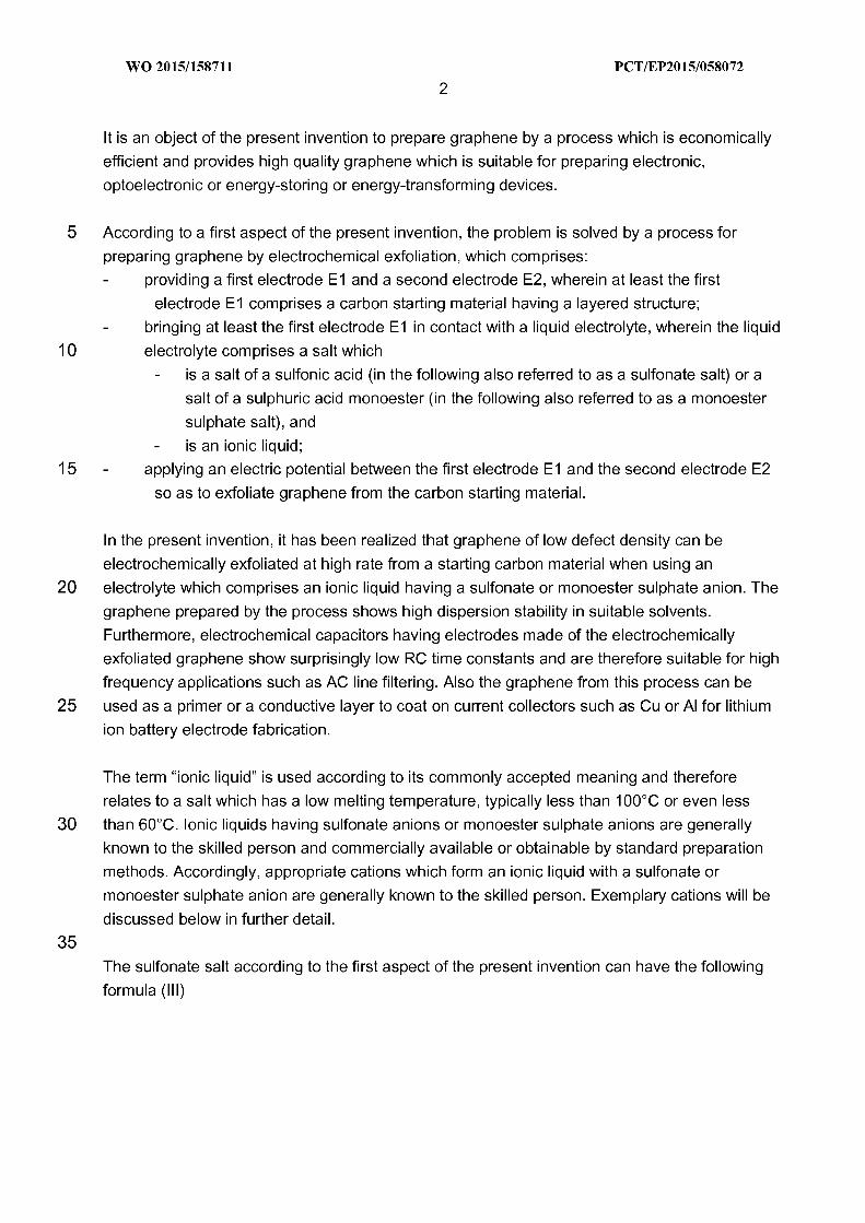
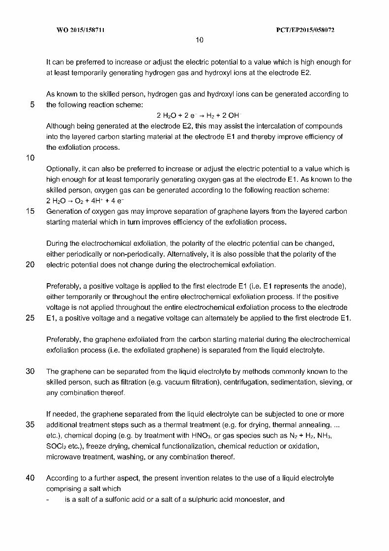
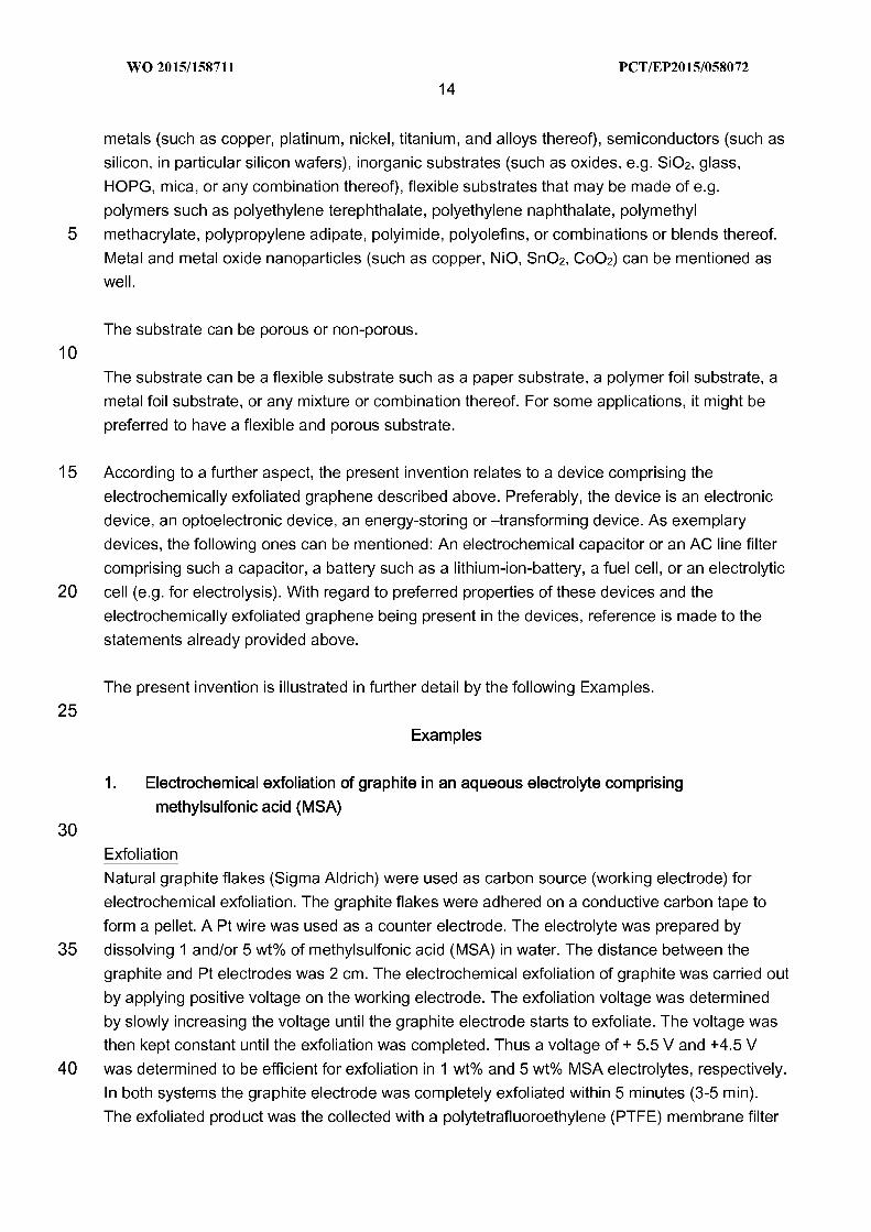
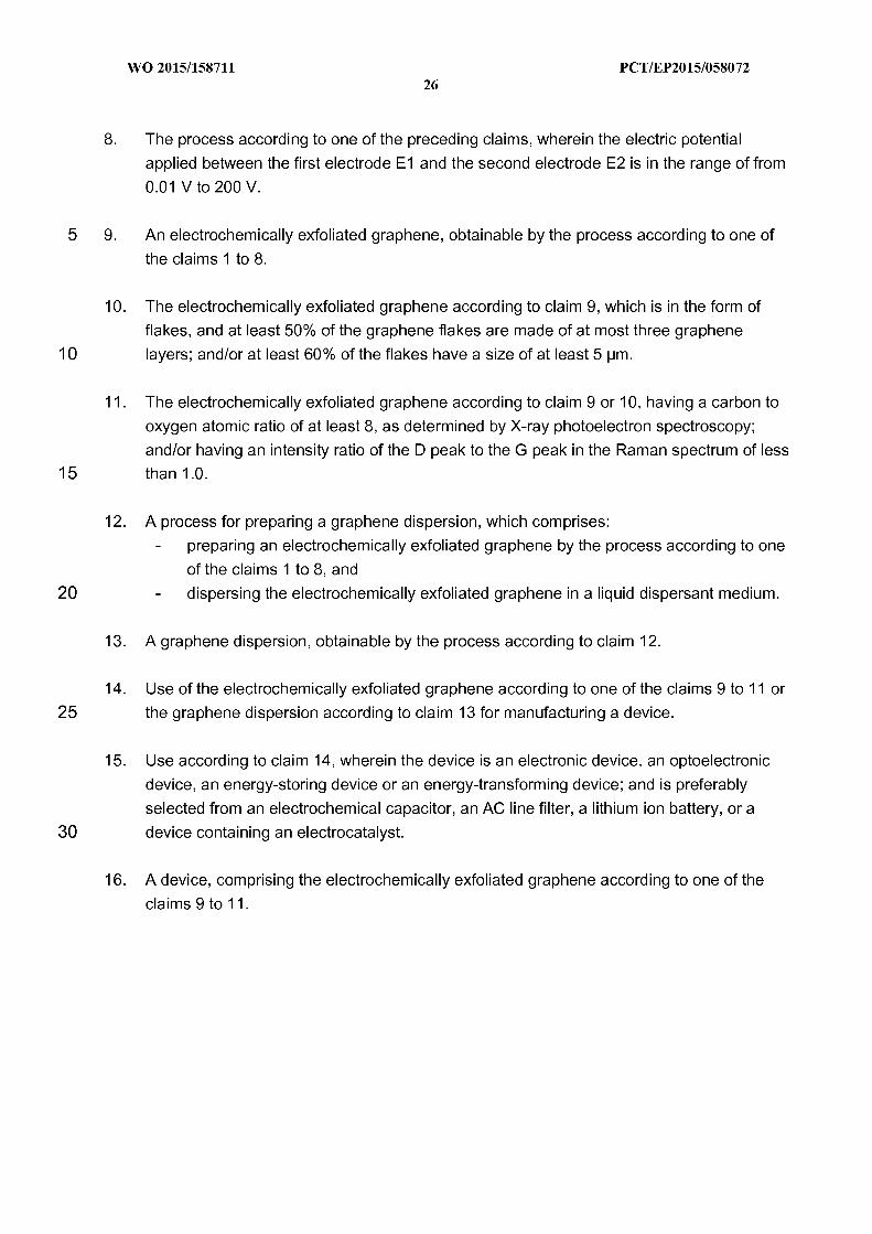
35 The Raman spectrum is shown in Figure 1 and provides the characteristic peaks for a few-layer-
graphene (D-peak at around 1350 cm-", G-peak at 1579 cm-", 2D-peak at 2700 cm-").
40
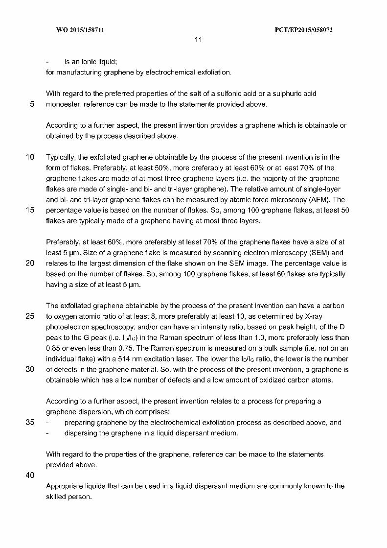
The XPS spectrum of the electrochemically exfoliated graphene is shown in Figure 2. The
graphene had an oxygen content of about 8%, and a carbon to oxygen atomic ratio of about
11.5.
WO 2015/158711
16PC T/EP2015/058072
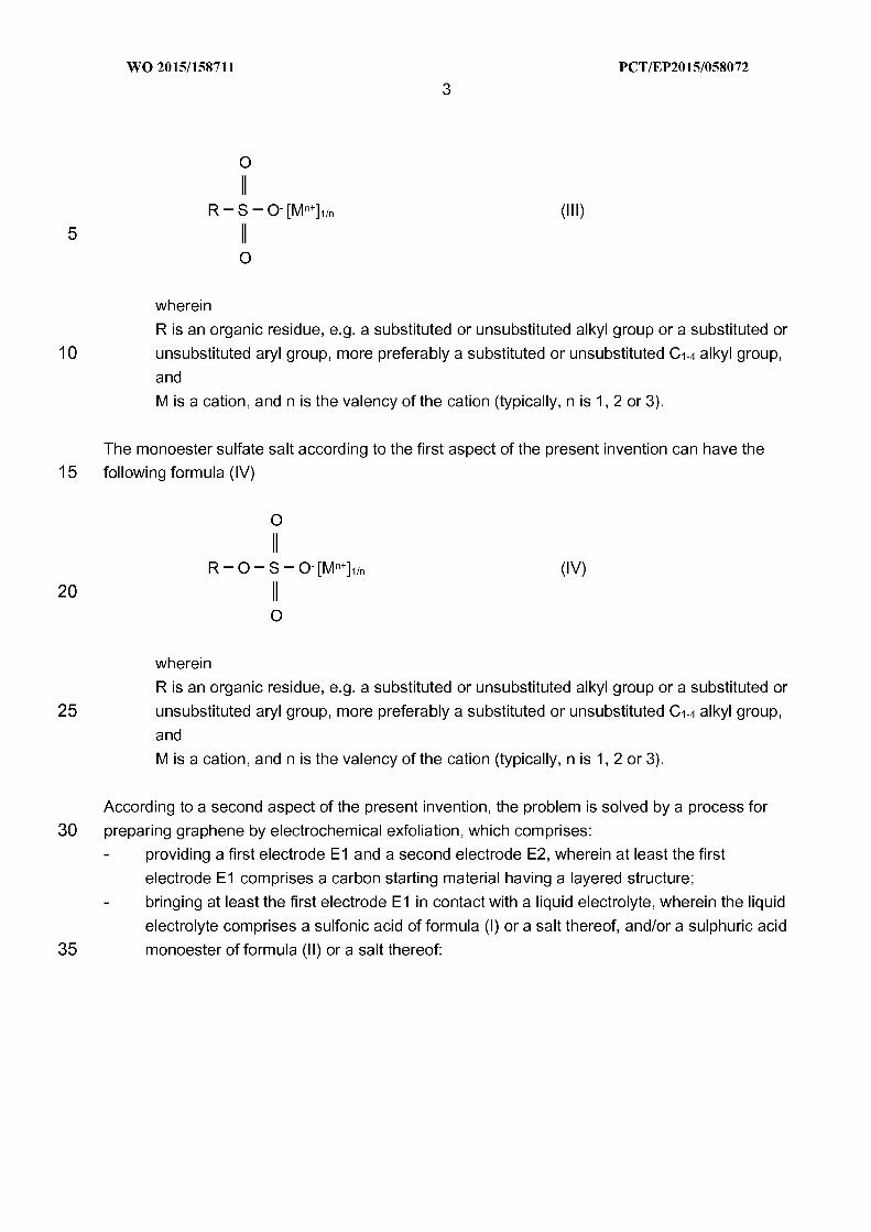
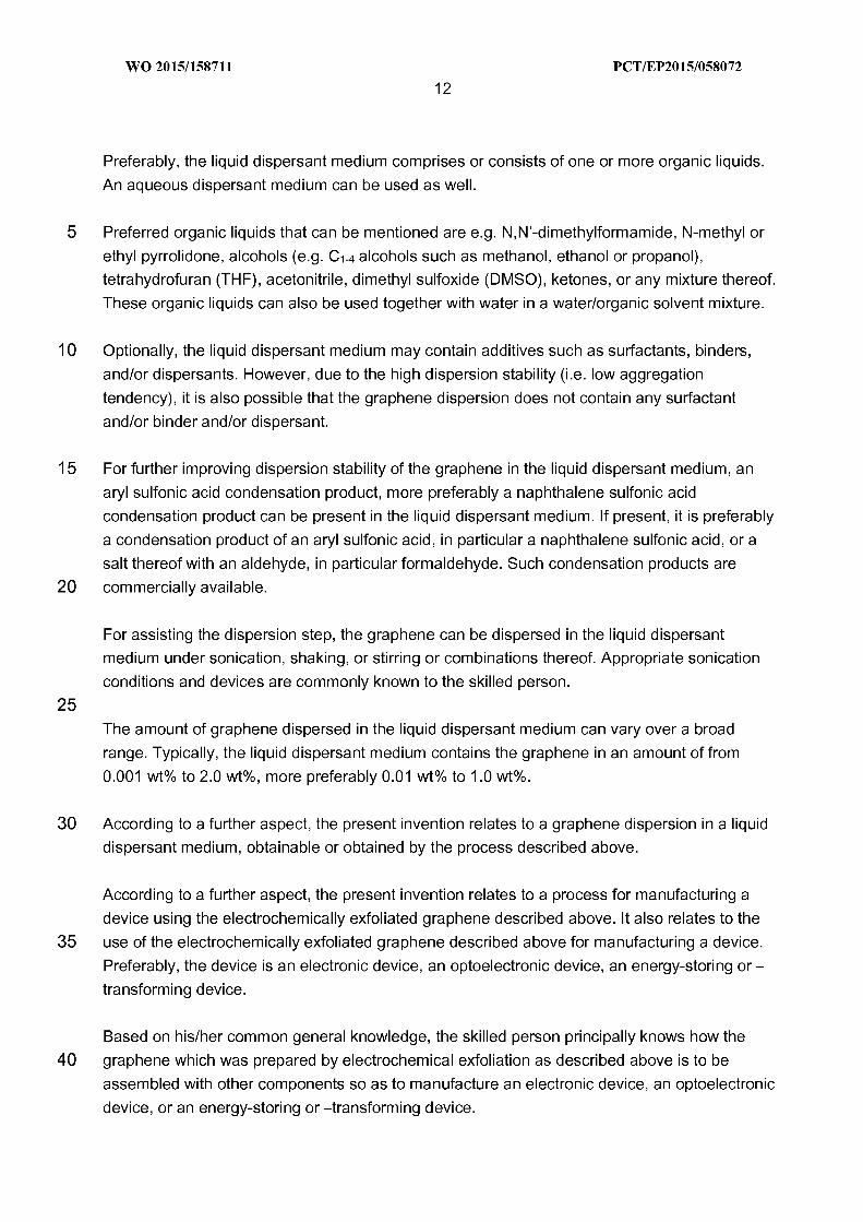
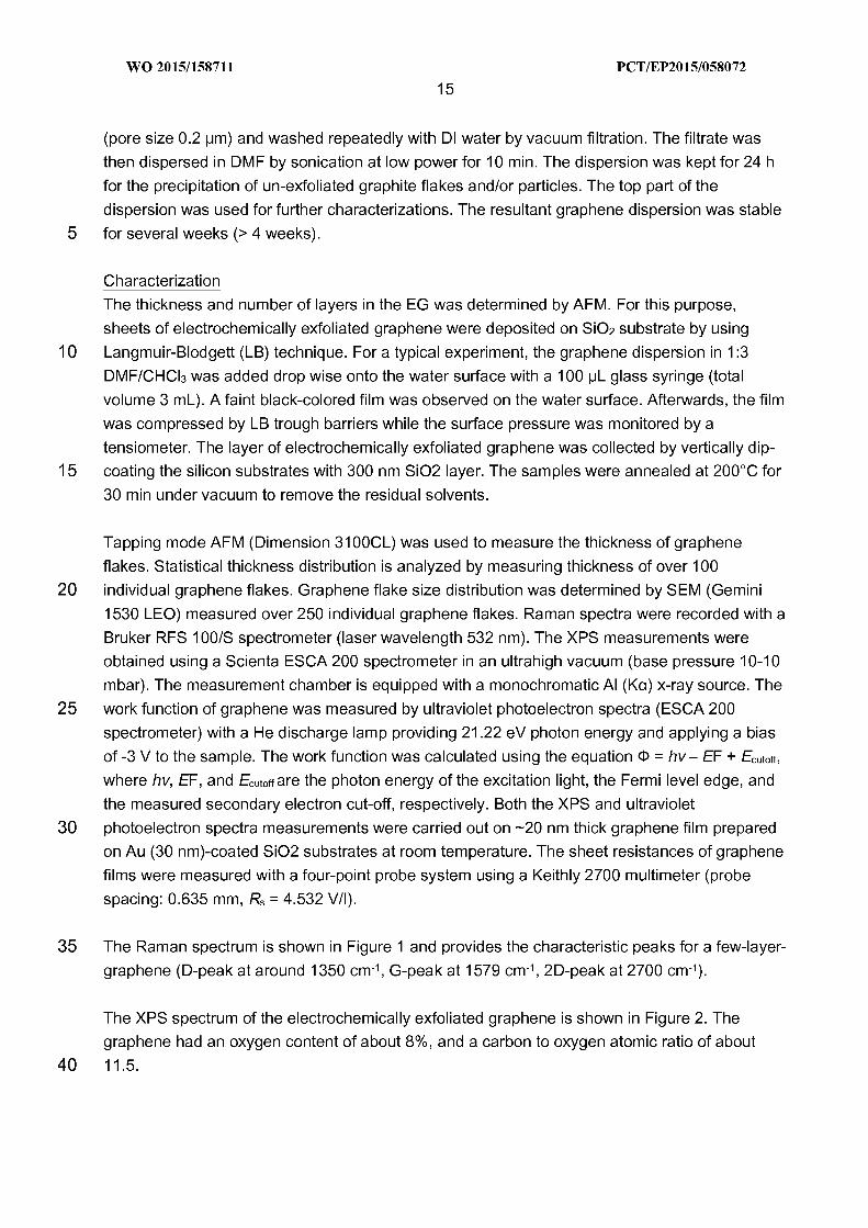
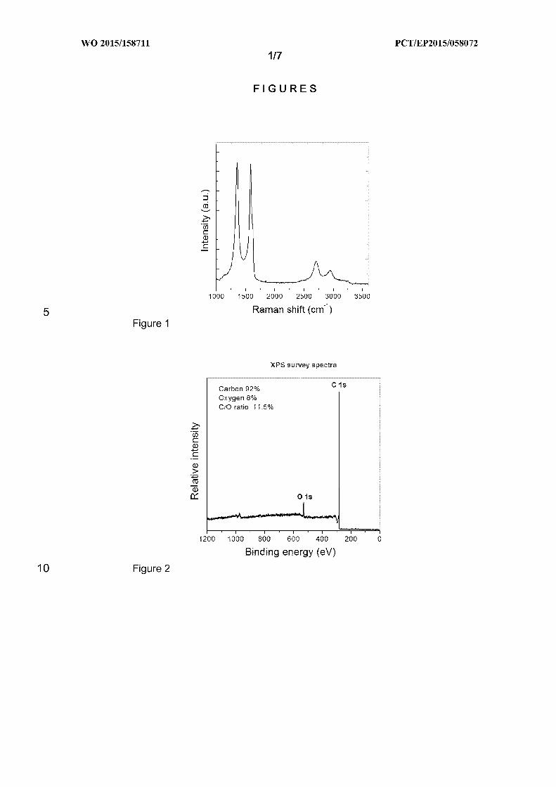
The graphene thickness distribution (expressed as "number of graphene layers" ) is shown in
Figure 3. There is a high percentage (more than 75 %) of graphene flakes made of "few-layer-
graphene" having three or less graphene layers.
Graphene flake size distribution is shown in Figure 4. There is a high percentage (about 70%) of
flakes having a flake size of at least 5 pm.
10
15
Thin film fabrication
Transparent graphene films on flexible polyethylene terephthalate (PET) substrates by a
vacuum filtration and dry transfer method. Briefly, a graphene dispersion of —0.4 mg/mL in
DMF) was vacuum-filtered through a polytetrafluoroethylene (PTFE) membrane followed by
mechanically pressing the filtered film against a PET substrate. Afterwards, the PTFE
membrane was peeled off, leaving the transferred graphene film on the substrate. Vacuum
filtration of 5 mL graphene dispersion resulted in a -45 nm thick film on PET with —54%transmittance (at 550 nm). For the heat treatment, another graphene film with similar thickness
was prepared on the glass substrate.
20
The sheet resistance (Rs) measured by a four-point probe system revealed a mean value of 8.2kQ/ immediately after the transfer. Low temperature annealing (i.e., 300'C) of the graphene
films decreased the Rs to 0.59 kQ/ .
25
Sheet resistance of the graphene film (without thermal annealing and with thermal annealing at
100'C, 200'C and 300'C) is shown in Figure 5. Even if there is no thermal annealing, a low
sheet resistance of 8.2 kOhm/ is achieved. By low-temperature annealing, sheet resistance
can be further reduced to very low values (100'C: 3.5 kOhm/; 200'C: 0.91 kOhm/; 300'C:0.59 kOhm/ ).
30
35
40
2. Electrochemical exfoliation of graphite in an aqueous electrolyte comprising a salt which is
an ionic liquid
Materials, chemicals and instrumentation. Graphite rods and graphite foil (Alfa Aesar, ), 1-ethyl-
3-methylimidazolium methanesulfonate (EMIM-MS), and 1-ethyl-3-methylimidazolium acetate
(EMIM-Ac). BioLogic cycler and Gamry potentiostat were used to apply the required voltage and
monitor the generated current.
The salts 1-ethyl-3-methylimidazolium methanesulfonate (EMIM-MS), and 1-ethyl-3-
methylimidazolium acetate (EMIM-Ac) are ionic liquids (i.e. salts having a low melting
temperature; m. p. (EMIM-MS): 35'C; m. p. (EMIM-Ac): & 20'C). Both are commercially available
(e.g. Basionics, BASF SE).
An aqueous electrolyte was prepared by adding the salt into water. Different salt concentrations
were tested. As electrodes, either graphite rods or graphite foils were used. Graphite foils were
WO 2015/158711
17PC T/EP2015/058072
produced by pressing thermally expanded graphite into thin sheets, and thermally expanded
graphite was produced from natural graphite flakes via intercalation.
Comparative Example: Aqueous electrol te comprisin 1-eth I-3-meth limidazolium acetate
5 EMIM-Ac as an ionic liquid
EMIM-Ac was tested at concentrations of 10 wt%, 25 wt%, 50 wt% and 80 wt% in water.
A voltage of 6 V was applied. Graphite rods were used as electrodes. In the electrochemical
10 exfoliation process of all tests, the graphite cathode was corroded, whereas the graphite anode
remained unaffected. The powdery material collected from the corroded cathode was not
dispersing in N-ethylpyrrolidone, which means that no few-layer-graphene could be obtained in
an electrolyte comprising EMIM-Ac.
15 Inventive Examples: Aqueous electrol te comprisin a sulfonate salt as an ionic liquid
20
1-Ethyl-3-methylimidazolium methanesulfonate (EMIM-MS) was tested at concentrations of 2
wt%, 5 wt%, 10 wt% and 20 wt% in water. The following voltages were applied for effecting
exfoliation (i.e. exfoliation potential):
2wt%: 10 V
5wt%: 8V10wt%: 6V20 wt%: 5V
25 In all tests, anodic exfoliation was observed. After the electrochemical exfoliation process was
over, the exfoliated material was separated from the electrolyte and thoroughly washed with
water using vacuum filtration. The obtained powder was dispersed in N-ethyl-pyrrolidone (NEP)
using bath sonication for 15 min. After that the dispersion was centrifuged 2600 rpm for 20 min
and supernatant was used for further characterization and testing.
30For AFM and Raman characterization the dispersion was drop-casted on Si/SIO~, for TEM
measurements —on carbon grids.
35
40
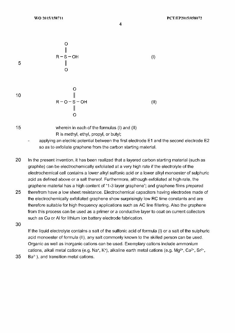
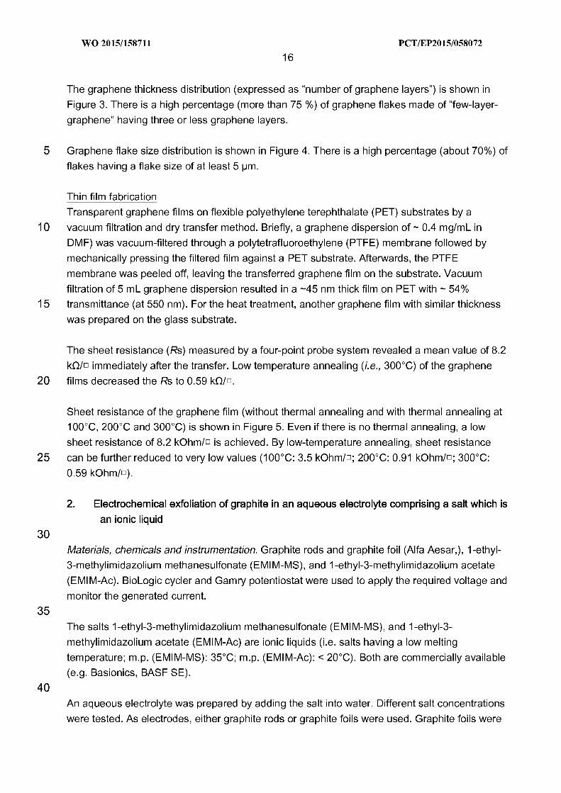
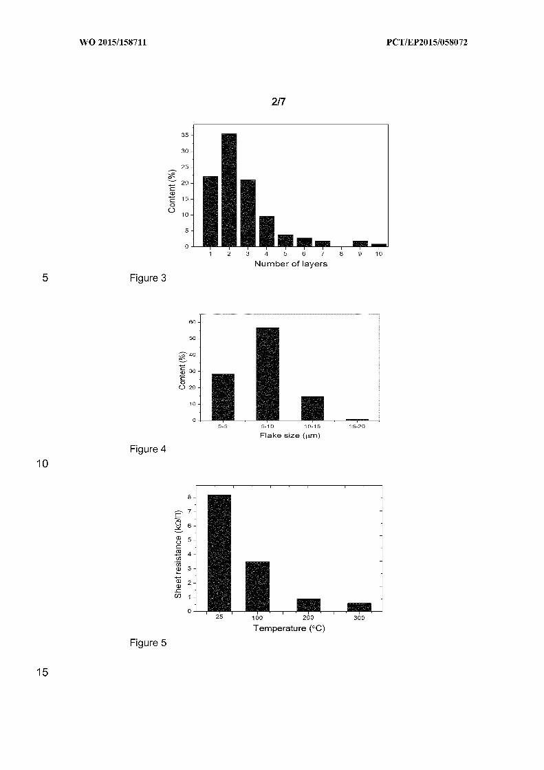
Raman measurements (using 514 nm laser) made on samples which had been
electrochemically exfoliated from graphite rods showed typical characteristic peaks for a few-
layer-graphene (D-peak at around 1350 cm ", G-peak at 1579 cm ", 2D-peak at 2700 cm ").This
is shown in Figure 6. The average value of ip/IG (i.e. ratio of intensities of the peaks D and G)
obtained from three measurement points was calculated for every sample. For graphene
produced in an electrolyte containing 2% EMIM-MS, lp/IG was 0.78. Electrolyte containing 5%EMIM-MS: Ip/IG was 0.82. Electrolyte containing 10% EMIM-MS: lp/IG was 0.67. Electrolyte
containing 20% EMIM-MS: lp/IG was 0.76.
WO 2015/158711
18PC T/EP2015/058072
A Raman measurement was also made on an individual graphene flake of a sample which had
been electrochemically exfoliated from a graphite foil. This is shown in Figure 7. Again, the
characteristic graphene peaks can be identified in the Raman spectrum. The ID/IG ratio was
0.25.
10
15
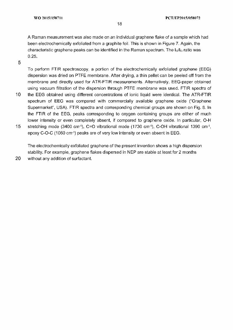
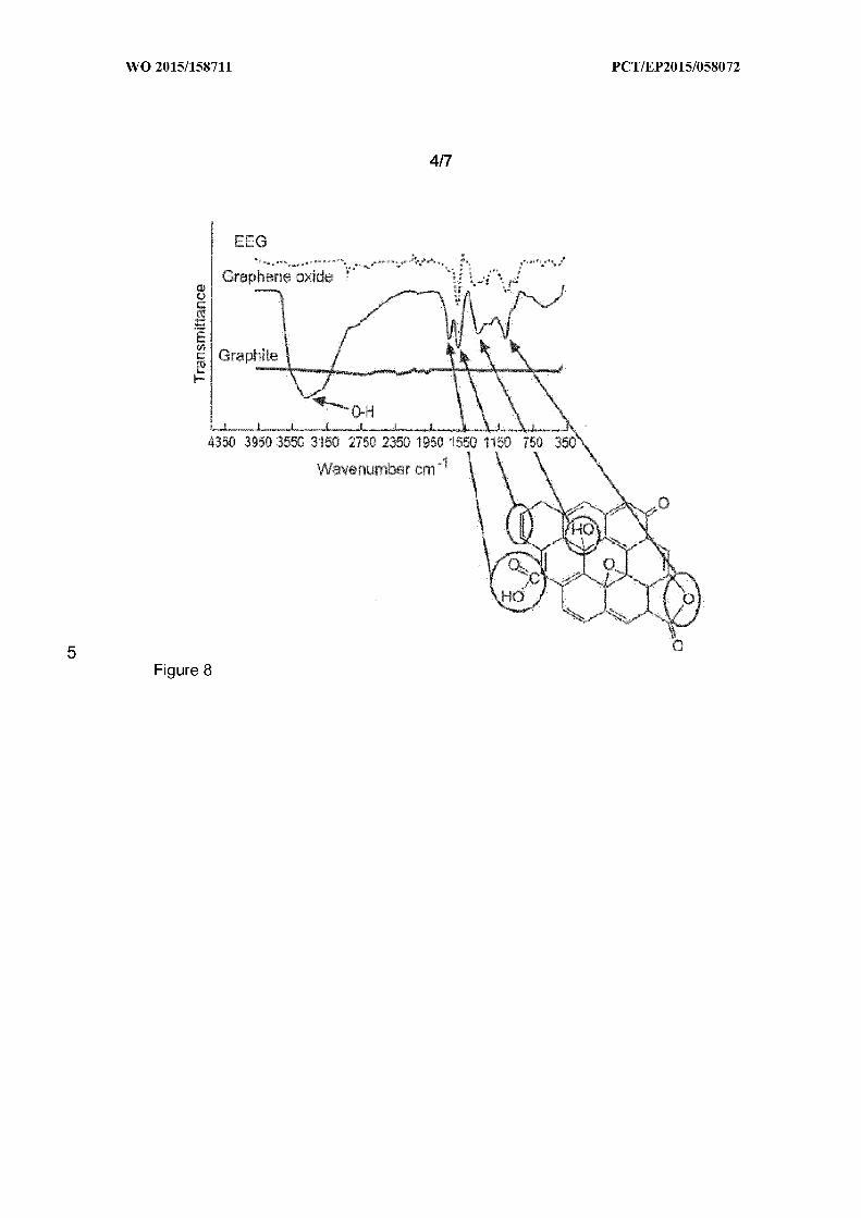
To perform FTIR spectroscopy, a portion of the electrochemically exfoliated graphene (EEG)dispersion was dried on PTFE membrane. After drying, a thin pellet can be peeled off from the
membrane and directly used for ATR-FTIR measurements. Alternatively, EEG-paper obtained
using vacuum filtration of the dispersion through PTFE membrane was used. FTIR spectra of
the EEG obtained using different concentrations of ionic liquid were identical. The ATR-FTIR
spectrum of EEG was compared with commercially available graphene oxide ("Graphene
Supermarket", USA). FTIR spectra and corresponding chemical groups are shown on Fig. 8. In
the FTIR of the EEG, peaks corresponding to oxygen containing groups are either of much
lower intensity or even completely absent, if compared to graphene oxide. In particular, 0-H
stretching mode (3400 cm"), C=O vibrational mode (1730 cm"), C-OH vibrational 1390 cm",
epoxy C-0-C (1060 cm-") peaks are of very low intensity or even absent in EEG.
20
The electrochemically exfoliated graphene of the present invention shows a high dispersion
stability. For example, graphene flakes dispersed in NEP are stable at least for 2 months
without any addition of surfactant.
WO 2015/158711
19PC T/EP2015/058072
3. Using the electrochemically exfoliated graphene for preparing electrochemical capacitors
suitable for AC line filtering
5 For preparing an electrochemical capacitor, the graphene dispersion which had been obtained
as described above by electrochemical exfoliation in the presence of 1-ethyl-3-
methylimidazolium methanesulfonate (EMIM-MS) was used.
Electrode preparation
10 Electrodes were prepared using EEG (electrochemically exfoliated graphite), which was
dispersed in NEP with the concentration of 1.5 mg/ml. It is a binderless technique where the as-
prepared graphene ink is drop-coated directly on current collectors (CC).
15
20
Prior to coating, the current collectors (either nickel foam or nickel foil) were punched out into a
12 mm diameter circular disks. They were cleaned in a sonication bath with isopropanol for 10
minutes, vacuum dried at 70oC for 2 hours and then weighed individually. 2 -3 pl of EEG ink
was dropped onto the nickel foam disks and vacuum dried at 70oC for 12 hours. This procedure
was repeated for the second coating before drying it completely in the vaccum oven for another
24 hours at 70oC before electrochemical capacitor fabrication. The weight of the active material
(EEG) was determined by subtracting bare nickel foam weight, taken prior to the drop coating,
from the active material coated nickel foam or foil.
Assembly and electrochemical characterizations of electrochemical capacitors
Symmetric two-electrode electrochemical capacitors were assembled in a stainless steel
25 electrochemical capacitor cell with titanium electrodes using microfiber glass separator of 20mm
in between two EEG coated nickel foam or foil. All electrochemical measurements were carried
out using 1M of potassium hydroxide (KOH) as the electrolyte. The electrochemical impedance
spectroscopy, cyclic voltammetry, and galvanostatic charge-discharge were measured using an
electrochemical workstation Biologic Potentiostat/Galvanostat MPG2 and Gamry MultiEchem
30 Potentiostat/Galvanostat/ZRA system at room temperature.
WO 2015/158711
20PC T/EP2015/058072
Example 1:Graphene was prepared by electrochemical exfoliation of a graphite rod (alternatively: a
graphite foil) in a 10 wt'/o aqueous solution of 1-ethyl-3-methylimidazolium methanesulfonate.
5 The electrochemically exfoliated graphene was provided on a nickel foam (acting as a current
collector) and the electrochemical capacitor was assembled following the procedure outlined
above.
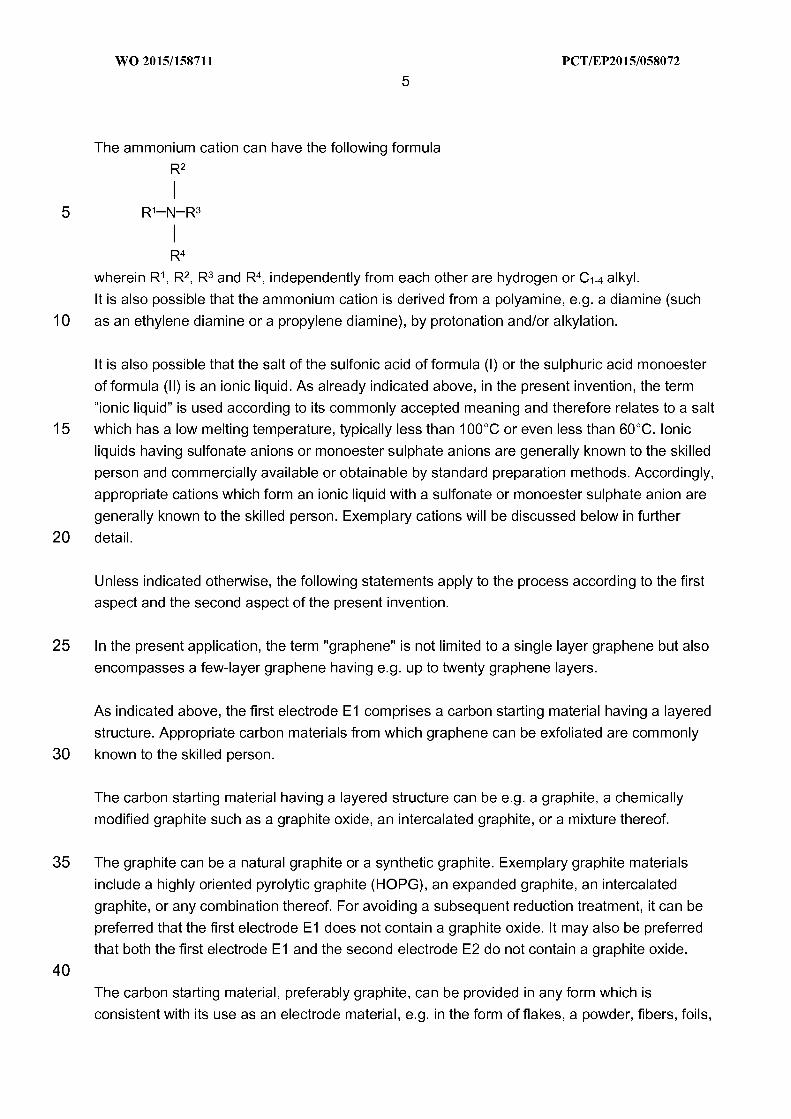
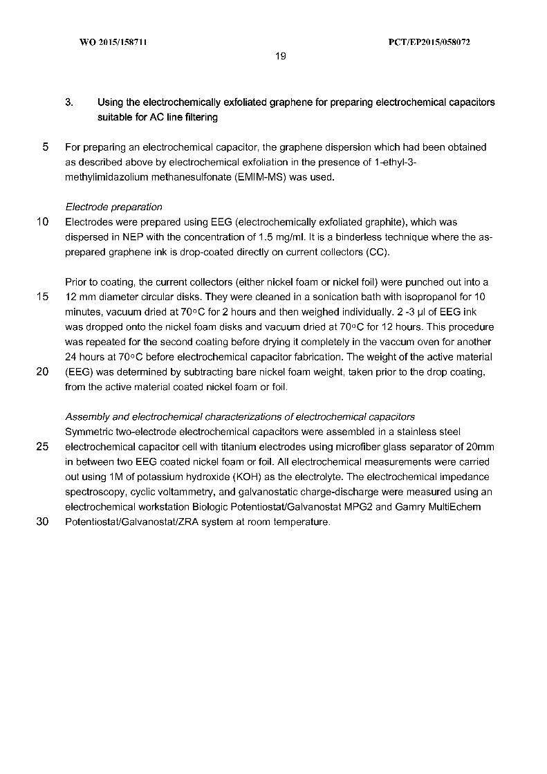
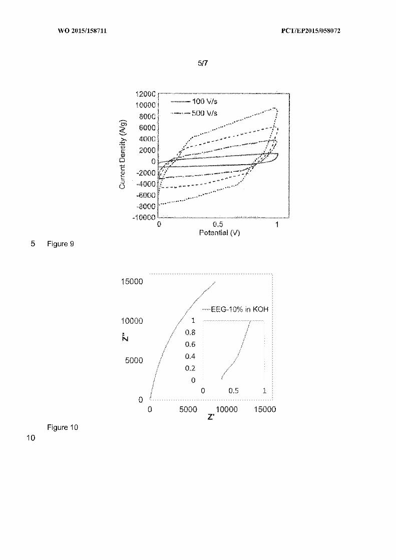
CV curves of the electrochemical capacitor obtained at different scan rates of 100 (solid line),
10 500 (dash-dotted line), 1000 (dashed line) and 2000 V s" (dotted line) are shown in Figure 9.The results indicate a typical electric double-layer capacitive behavior even at ultrahigh scan
rates, demonstrating its ultrahigh power ability. An ultra-fast charging/discharging capability of
2000 V/s is achieved.
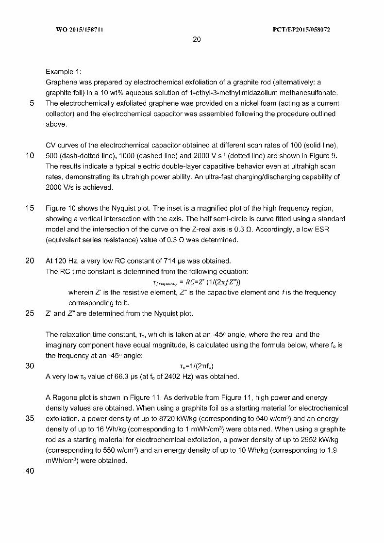
15 Figure 10 shows the Nyquist plot. The inset is a magnified plot of the high frequency region,
showing a vertical intersection with the axis. The half semi-circle is curve fitted using a standard
model and the intersection of the curve on the Z-real axis is 0.3 Q. Accordingly, a low ESR
(equivalent series resistance) value of 0.3 Q was determined.
20
25
At 120 Hz, a very low RC constant of 714 ps was obtained.
The RC time constant is determined from the following equation:
r/reqUency = RC=Z' (1/(2Tr fZ"))wherein Z' is the resistive element, 2" is the capacitive element and f is the frequency
corresponding to it.
Z' and 2"are determined from the Nyquist plot.
30
The relaxation time constant, T„which is taken at an -45O angle, where the real and the
imaginary component have equal magnitude, is calculated using the formula below, where f. is
the frequency at an -45O angle:
T,=1/(2TTf, )
A very low T. value of 66.3 ps (at f. of 2402 Hz) was obtained.
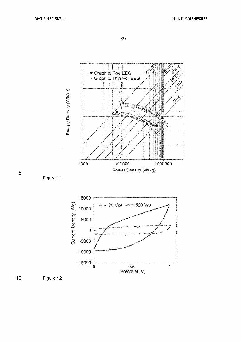
A Ragone plot is shown in Figure 11.As derivable from Figure 11, high power and energy
density values are obtained. When using a graphite foil as a starting material for electrochemical
35 exfoliation, a power density of up to 8720 kW/kg (corresponding to 540 w/cm') and an energy
density of up to 16 Wh/kg (corresponding to 1 mWh/cm') were obtained. When using a graphite
rod as a starting material for electrochemical exfoliation, a power density of up to 2952 kW/kg
(corresponding to 550 w/cm') and an energy density of up to 10 Wh/kg (corresponding to 1.9mWh/cm') were obtained.
40
WO 2015/158711
21PC T/EP2015/058072
The energy and power densities were determined using the equations below;
E = 0.5 x C V' (in Wh/kg)
V: discharge voltage range (in volts)
5 C: discharge capacitance (in Farads)
10
P =E/t (in W/kg)
E: Energy density
t: discharge time (in seconds)
Example 2:Graphene was prepared by electrochemical exfoliation of a graphite rod in a 2 wt% aqueous
solution of 1-ethyl-3-methylimidazolium methanesulfonate.
The electrochemically exfoliated graphene was provided on a nickel foil (acting as a current
15 collector) and the electrochemical capacitor was assembled following the procedure outlined
above.
CV curves of the electrochemical capacitor obtained at different scan rates of 70 and 500 V s"are shown in Figure 12. The results indicate a typical electric double-layer capacitive behavior
20 even at ultrahigh scan rates, demonstrating its ultrahigh power ability. An ultra-fast
charging/discharging capability of 500 V/s is achieved.
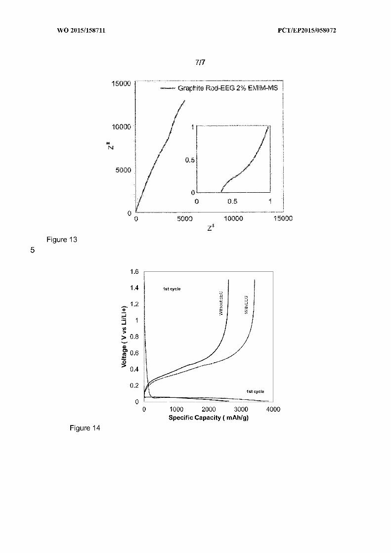
Figure 13 shows the Nyquist plot. The inset is a magnified plot of the high frequency region,
showing a vertical intersection with the axis. A low ESR (equivalent series resistance) value of
25 about 0.3 Q was determined.
30
At 120 Hz, a very low RC constant of 613 ps (when using a graphite rod as a starting material
for electrochemical exfoliation) and 616 ps (when using a graphite foil as a starting material for
electrochemical exfoliation), respectively, was obtained.
The relaxation time constant, T„which is taken at an -45O angle, where the real and the
imaginary component have equal magnitude, is calculated using the formula below, where f. is
the frequency at an -45O angle:
T,=1/(2TTf, )
35 A very low T. value of 253 ps was obtained at 629 Hz (f. value at -45').
Accordingly, as demonstrated by the Examples, an electrochemical capacitor having electrodes
made of the electrochemically exfoliated graphene of the present invention has a surprisingly
low RC time constant at 120 Hz. Other relevant capacitor properties, in particular
40 charging/discharging capability, power and energy densities, and ESR value are also on a very
high level. Due to its very low RC time constant in combination with the other beneficial
properties, the electrochemical capacitor is very suitable for AC line filtering. Thus, the
WO 2015/158711
22PC T/EP2015/058072
electrochemically exfoliated graphene of the present invention is not only obtainable by an
economically efficient and easy-to-perform method but also enables the preparation of
electrochemical capacitors having surprisingly low RC time constants.
5 4. Using the electrochemically exfoliated graphene for preparing a lithium ion battery
10
A lithium ion battery having an anode comprising silicon, a copper current collector, and an
electrochemically exfoliated graphene located in between the silicon-containing anode and the
current collector was prepared as follows:
Following the procedure described above, graphene was prepared by electrochemical
exfoliation in an aqueous electrolyte containing EMIM-MS (i.e. an aqueous electrolyte in which
an ionic liquid is dissolved).
15 A graphene film was deposited on a copper foil (acting as a current collector) using Langmuir-
Blodgett assembly technique.
20
25
The working electrode (anode) was prepared by dispersing a nanosized Si powder (average
particle size (APS) = 50nm, Alfa Aesar), Conductive black —Super P C65 (Timcal), and
poly(acrylic acid) (PAA) (MW = 450.000) in a weight ratio of 63:22:15, in Dl water and methanol.
The mixture was stirred for 3 h until a homogeneous slurry is obtained. The slurry was then
casted onto the graphene-coated copper foil using the doctor blade method (coating thickness
of 200 Ijm), followed by drying overnight (24h) in a vacuum drying chamber at a temperature of
70 'C. A half cell was assembled using the punched-out Si electrodes of 14 mm diameter as the
working electrode against a lithium metal as the counter and reference electrode, employing 1M
LIPF6 in EC: EMC: FEC (3:6:1)as electrolyte.
30
As a reference, a graphene-free lithium ion battery was prepared according to the method
described above.
For the initial SEI formation, the half cell was cycled at C/10 for 20 cycles, followed by C/5 for 50
cycles and C/2 for 100 cycles between 0.01 and 1.5 V. All measurements were carried out at
room temperature (25'C).
35 In Figure 14, voltage as a function of specific capacity is shown.
The following properties are derivable from Figure 14:
Li-ion battery containing the electrochemically exfoliated graphene:
40 Discharge capacity (1"cycle ): 3853 mAh/g
Charge capacity (1"cycle ): 3421 mAh/g
WO 2015/158711
23PC T/EP2015/058072
Graphene-free Li-ion battery:
Discharge capacity (1"cycle ): 2586 mAh/g
Charge capacity (1"cycle ): 2612 mAh/g
5 As demonstrated by the experimental data, charge and discharge capacity are clearly improved
when a layer of electrochemically exfoliated graphene is present (in between the current
collector and the anode).
WO 2015/15871124
PC T/EP2015/058072
CLAIMS
10
15
A process for preparing graphene by electrochemical exfoliation, which comprises:
providing a first electrode E1 and a second electrode E2, wherein at least the first
electrode E1 comprises a carbon starting material having a layered structure;
bringing at least the first electrode E1 in contact with a liquid electrolyte, wherein the
liquid electrolyte comprises a sulfonic acid of formula (I) or a salt thereof, and/or a
sulphuric acid monoester of formula (II) or a salt thereof:
0
R —S —OH
0
20
0
R —0 —S —OH
0
25wherein in each of the formulas (I) and (II)
R is methyl, ethyl, propyl, or butyl;
applying an electric potential between the first electrode E1 and the second
electrode E2 so as to exfoliate graphene from the carbon starting material.
302. The process according to claim 1, wherein the salt of the sulfonic acid of formula (I) or the
salt of the sulphuric acid monoester of formula (II) is an ionic liquid.
35
40
A process for preparing graphene by electrochemical exfoliation, which comprises:
providing a first electrode E1 and a second electrode E2, wherein at least the first
electrode E1 comprises a carbon starting material having a layered structure;
bringing at least the first electrode E1 in contact with a liquid electrolyte, wherein the
liquid electrolyte comprises a salt which
is a salt of a sulfonic acid or a salt of a sulphuric acid monoester, and
is an ionic liquid;
applying an electric potential between the first electrode E1 and the second
electrode E2 so as to exfoliate graphene from the carbon starting material.
WO 2015/15871125
PC T/EP2015/058072
4. The process according to claim 3, wherein the salt of the sulfonic acid has the following
formula (II I)
0
R S 0 [M"'])an
0
10
15
wherein
R is an organic residue, and
M is a cation, and n is the valency of the cation;
and
the salt of the sulphuric acid monoester has the following formula (IV)
20
0
R —0 —S —0 [M"']as,
0
(IV)
25
30
wherein
R is an organic residue, and
M is a cation, and n is the valency of the cation.
The process according to one of the preceding claims, wherein the carbon starting
material having a layered structure is a graphite, a chemically modified graphite, an
intercalated graphite, or a mixture thereof; and/or the liquid electrolyte is an aqueous
electrolyte.
6. The process according to one of the claims 2 to 5, wherein the cation of the ionic liquid is
a heterocyclic cation, an ammonium cation, or a phosphonium cation, or a mixture thereof.
35
40
7. The process according to claim 6, wherein the heterocyclic cation is a nitrogen-containing
heterocyclic cation, which is preferably selected from an imidazolium cation, a pyridinium
cation, a pyrrolidinium cation, a pyrazolium cation, a pyridazinium cation, a pyrimidinium
cation, a pyrazinium cation, an oxazolium cation, a triazolium cation, a thiazolium cation, a
piperidinium cation, a quinolium cation, an isoquinolium cation, a benzimidazolium cation,
or any mixture thereof.
WO 2015/15871126
PC T/EP2015/058072
8. The process according to one of the preceding claims, wherein the electric potential
applied between the first electrode E1 and the second electrode E2 is in the range of from
0.01 V to 200 V.
5 9. An electrochemically exfoliated graphene, obtainable by the process according to one of
the claims 1 to 8.
10
10. The electrochemically exfoliated graphene according to claim 9, which is in the form of
flakes, and at least 50% of the graphene flakes are made of at most three graphene
layers; and/or at least 60% of the flakes have a size of at least 5 pm.
15
11. The electrochemically exfoliated graphene according to claim 9 or 10, having a carbon to
oxygen atomic ratio of at least 8, as determined by X-ray photoelectron spectroscopy;
and/or having an intensity ratio of the D peak to the G peak in the Raman spectrum of less
than 1.0.
20
12. A process for preparing a graphene dispersion, which comprises:
preparing an electrochemically exfoliated graphene by the process according to one
of the claims 1 to 8, and
dispersing the electrochemically exfoliated graphene in a liquid dispersant medium.
13. A graphene dispersion, obtainable by the process according to claim 12.
2514. Use of the electrochemically exfoliated graphene according to one of the claims 9 to 11 or
the graphene dispersion according to claim 13 for manufacturing a device.
30
15. Use according to claim 14, wherein the device is an electronic device, an optoelectronic
device, an energy-storing device or an energy-transforming device; and is preferably
selected from an electrochemical capacitor, an AC line filter, a lithium ion battery, or a
device containing an electrocatalyst.
16. A device, comprising the electrochemically exfoliated graphene according to one of the
claims 9 to 11.
WO 2015/158711
1/7PC T/EP2015/058072
FIGURES
Figure 1
1000 1500 2000 2500 3000 3500
Raman shift (cm )
XpS sun/ey speotra
Carbon 92'/o
Oxygen 8'/o
C/0 ratio 11.5'/o
O1s
Figure 2
1200 1000 BGG 600 490 200 0
Binding energy (eV)
WO 2015/158711 PC T/EP2015/058072
2/7
30
25
20
0)15
10
Figure 3
1 2 3 4 5 6 r 6 9 10
Number of layers
50
50
~o 40
~ 30C
20
10
Figure 4
5-1 0 10-15Flake size (pm)
15-20
7
6
C30)
4M
0) 3
0)
CO
Figure 5
25 100 200
Temperature ( C)300
15
WO 2015/158711 PC T/EP2015/058072
3/7
Figure 6
10Figure 7
RemerI std, cm
WO 2015/158711 PC T/EP2015/058072
4/7
EE9
6r8phite
Figure 8
WO 2015/158711 PC T/EP2015/058072
5/7
—Ilo0 Vfs
5O0 V/s
5 Figure 9
0,5Potentiall (V)
35OOO
0
10Figure 10
5OOO )OOOO 15OOOZw
WO 2015/158711 PC T/EP2015/058072
6/7
Figure 11
" 70 V/s —500 V/s
Figure 12
-10000
-15000D 0,5
PGteAIIII8) IV
WO 2015/158711 PC T/EP2015/058072
7/7
5000 15000
Figure 13
1.4 1st cycle
1.2+
1
) 0.8
m 0.60
0.4
0.2est cycle
Figure 14
1000 2000 3000 4000Specific Capacity ( mAh/9)
INTERNATIONAL SEARCH REPORT
A. CLASSIFICATION OF SUBJECT MATTER
I NV. C25B1/88ADD.
International application No
PCT/ E P2815/858872
According to International Patent Classification (IPC) or to both national classification and IPC
B. FIELDS SEARCHED
Minimum documentation searched (classification system followed by classification symbols)
C25B
Documentation searched other than minimum documentation to the extent that such documents are included in the fields searched
Electronic data base consulted during the international search (name of data base and, where practicable, search terms used)
EPO- Internal
C. DOCUMENTS CONSIDERED TO BE RELEVANT
Category* Citation of document, with indication, where appropriate, of the relevant passages Relevant to claim No.
X
A
US 2813/881889 A1 (LI LAIN-JONG [TW] ET
AL) 3 January 2813 (2813-81-83)cited in the applicationclaims 1-33
1,5, 8
X HURAT ALANYALOLU ET AL: "The synthesis ofgraphene sheets with controlled thicknessand order using surfactant-assistedelectrochemical processes",CARBON, ELSEVIER, OXFORD, GB,vol. 58, no. 1, 19 July 2811 (2811-87-19),pages 142-152, XP828387882,ISSN: 8888-6223, DOI:18.1816/J.CARBON. 2811.87.864[retri eved on 2811-88-18]the whole document
1,5,8-16
* Special categories of cited documents:
"A" document defining the general state of the art which is not consideredto be of particular relevance
"E" earlier application or patent but published on or after the internationalfiling date
"L" document which may throw doubts on priority claim(s) or which iscited to establish the publication date of another citation or otherspecial reason (as specified)
"0" document referring to an oral disclosure, use, exhibition or othermeans
"P" document published prior to the international filing date but later thanthe priority date claimed
Date of the actual completion of the international search
"T" later document published after the international filing date or prioritydate and not in conflict with the application but cited to understandthe principle or theory underlying the invention
"X" document of particular relevance; the claimed invention cannot beconsidered novel or cannot be considered to involve an inventivestep when the document is taken alone
"Y" document of particular relevance; the claimed invention cannot beconsidered to involve an inventive step when the document iscombined with one or more other such documents, such combinationbeing obvious to a person skilled in the art
"8" document member of the same patent family
Date of mailing of the international search report
14 July 2815 22/87/2815
Name and mailing address of the ISA/
European Patent Office, P.B. 5818 Patentlaan 2NL - 2280 HV Rijswijk
Tel. (+31-70) 340-2040,Fax: (+31-70) 340-3016
Authorized officer
Hammerstein, G
Form PCT/ISA/2t 0 (second sheet) (Apnl 2005)
page 1 of 2
INTERNATIONAL SEARCH REPORT
C(Continuation). DOCUMENTS CONSIDERED TO BE RELEVANT
Categor)/* Citation of document, with indication, where appropriate, of the relevant passages
EUN HYE J00 ET AL: "ElectrochemicallyPreparation of Functionalized GrapheneUsing Sodium Dodecyl Benzene Sulfonate(SDBS)",ADVANCED IUIATERIALS RESEARCH TRANS TECH
PUBLICATIONS LTD, CH,vol. 747, 1 January 2813 (2813-81-81),pages 246-249, XP889188926,ISSN: 1822-6688, DOI:18 4828/WWW SCIENTIFIC NET/AIUIR 747 246the whole document
GB 2 488 825 A (IUIORGANITE ELECT CARBON
[GB]) 12 September 2812 (2812-89-12)claims 1,18-13; table 2
WANG G ET AL: "Highly efficient andlarge-scale synthesis of graphene byelectrolytic exfoliation",CARBON, ELSEVIER, OXFORD, GB,vol. 47, no. 14,1 November 2889 (2889-11-81), pages3242-3246, XP826575833,ISSN: 8888-6223, DOI:18.1816/J.CARBON. 2889.87.848[retrieved on 2889-87-19]the whole document
US 2813/299359 A1 (LING YONG-CHI EN [TW] ET
AL) 14 November 2813 (2813-11-14)paragraph [8888] - paragraph [8815]paragraph [8842]
International application No
PCT/ E P2815/858872
Relevant to claim No.
1,5,8-16
3-5,8
3-5,8-16
3-13
Form PCT/ISA/2t 0 (continuation of second sheet) (Apnl 2005)
page 2 of 2
INTERNATIONAL SEARCH REPORTInformation on patent family members
International application No
PCT/ E P2815/858872
Patent documentcited in search report
Publicationdate
Patent familymember(s)
Publicationdate
US 2813881889 A1 83-81-2813 NONE
GB 2488825 A 12-89-2812 GB 2488825 A
GB 2583838 A
WO 2812128291 A1
12-89-281288-81-281413-89-2812
US 2813299359 A1 14-11-2813 TW 281345835 A
US 2813299359 A1
16-11-281314-11-2813
Form PCT/ISA/2t 0 (patent family annex) (Apnl 2005)

![PatentOrderpdfstore.patentorder.com/pdf/wo/949/wo16136949.pdfWO 2016/136949 PC T/JP2016/055844 [8887] [888'] [8889] [8818] [88«] [8812] [881'] ~&6,,03N@~I|44%@7f54. kf=, 4&403.I|4403diktk,](https://img.pdfslide.us/doc/110x75/5fa7589f3d229e4e023d2b33/wo-2016136949-pc-tjp2016055844-8887-888-8889-8818-88-8812-881.jpg)