Embed Size (px)
Citation preview

RGB ELEKTRONIKA AGACIAK CIACIEKSPÓŁKA JAWNA Jana Dlugosza 2-6 Street51-162 WrocławPoland
[email protected] +48 71 325 15 05
www.rgbautomatyka.pl
www.rgbelektronika.pl
DATASHEET
www.rgbautomatyka.plwww.rgbelektronika.pl
OTHER SYMBOLS:
ARS2310
METRONIX

YOUR PARTNER IN MAINTENANCE
At our premises in Wrocław, we have a fully equipped servicing facility. Here we perform all the repair works and test each later sold unit. Our trained employees, equipped with a wide variety of tools and having several testing stands at their disposal, are a guarantee of the highest quality service.
OUR SERVICES
ENCODERS
SERVO DRIVERS
LINEAR ENCODERS
SERVO AMPLIFIERS
CNC MACHINES
MOTORS
POWER SUPPLIERS
OPERATOR PANELS
CNC CONTROLS
INDUSTRIAL COMPUTERS
PLC SYSTEMS
Repair this product with RGB ELEKTRONIKA ORDER A DIAGNOSIS
Buy this product at RGB AUTOMATYKA BUY

Servo Positioning Controller ARS 2302ARS 2305ARS 2310
Product Manual
Metronix Meßgeräte und Elektronik GmbH Telefon: +49-(0)531-8668-0
Kocherstraße 3 Telefax: +49-(0)531-8668-555
D-38120 Braunschweig E-mail: [email protected]
Germany http://www.metronix.de

Page 2 Technologiemodule
Copyrights
2011 Metronix Meßgeräte und Elektronik GmbH. All rights reserved.
The information and data in this document have been composed to the best of our knowledge. However, deviations between the document and the product cannot be excluded entirely. For the devices and the corresponding software in the version handed out to the customer, Metronix guarantees the contractual use in accordance with the user documentation. In the case of serious deviations from the user documentation, Metronix has the right and the obligation to repair, unless it would involve an unreasonable effort. A possible liability does not include deficiencies caused by deviations from the operating conditions intended for the device and described in the user documentation.
Metronix does not guarantee that the products meet the buyer’s demands and purposes or that they work together with other products selected by the buyer. Metronix does not assume any liability for damages resulting from the combined use of its products with other products or resulting from improper handling of machines or systems.
Metronix Meßgeräte und Elektronik GmbH reserves the right to modify, amend, or improve the document or the product without prior notification.
This document may, neither entirely nor in part, be reproduced, translated into any other natural or machine-readable language nor transferred to electronic, mechanical, optical or any other kind of data media, without expressive authorisation by the author.
Trademarks
Any product names in this document may be registered trademarks. The sole purpose of any trademarks in this document is the identification of the corresponding products.
ServoCommander™ is a registered trademark of Metronix Meßgeräte und Elektronik GmbH.
Product Manual “Servo Positioning Controller ARS 2302 ARS 2305 ARS 2310“ Version 4.0

Technologiemodule Seite 3
Revision Log
Author: Metronix Meßgeräte und Elektronik GmbH
Manual name: Product Manual "Servo Positioning Controller ARS 2302 ARS 2305 ARS 2310"
File name: P-HB_ARS2302-2310_4p0_EN_mBre.odt
Storage location of the file:
No. Description Revision index Date of change
001 Creation 1.0 11.06.2005
002 Translation 1.1 21.10.2005
003 Release for distribution 2.0 09.03.2006
004 Release 2.1 15.01.2007
005 Release 2.2 23.02.2010
006 Updated Corporate Identity – No technical changes
3.0 18.04.2011
007 Changes in chapter 2.2, reworked “List of Figures”
4.0 28.06.2011
Product Manual “Servo Positioning Controller ARS 2302 ARS 2305 ARS 2310“ Version 4.0

Page 4 Technologiemodule
TABLE OF CONTENTS:
1 GENERAL................................................................................................................12
2 SAFETY NOTES FOR ELECTRICAL DRIVES AND CONTROLS.........................14
3 PRODUCT DESCRIPTION......................................................................................23
4 TECHNICAL DATA..................................................................................................29
5 FUNCTION OVERVIEW..........................................................................................39
6 FUNCTIONAL SAFETY TECHNOLOGY................................................................49
7 MECHANICAL INSTALLATION..............................................................................60
8 ELECTRICAL INSTALLATION...............................................................................66
9 START-UP................................................................................................................99
10 SERVICE FUNCTIONS AND ERROR MESSAGES...........................................101
11 TECHNOLOGIEMODULE...................................................................................116
Product Manual “Servo Positioning Controller ARS 2302 ARS 2305 ARS 2310“ Version 4.0

Technologiemodule Seite 5
List of Figures:
Product Manual “Servo Positioning Controller ARS 2302 ARS 2305 ARS 2310“ Version 4.0

Page 6 Technologiemodule
FIGURE 1: TYPE KEY................................................................................................23
FIGURE 2: ARS 2310 CURRENT DERATING GRAPH............................................32
FIGURE 3: ARS 2300 CONTROL STRUCTURE.......................................................40
FIGURE 4: ARS 2300 SERVO POSITIONING CONTROLLER DRIVING PROFILES45
FIGURE 5: PATH PROGRAM....................................................................................46
FIGURE 6: LINEAR INTERPOLATION BETWEEN TWO DATA VALUES..............48
FIGURE 7: BLOCK DIAGRAM “SAFE TORQUE-OFF” AS PER EN ISO 13849-1, PERFORMANCE LEVEL D................................................................................51
FIGURE 8: TIMING OF “SAFE TORQUE-OFF” AS PER EN ISO 13849-1, PERFORMANCE LEVEL D................................................................................53
FIGURE 9: EMERGENCY-OFF CIRCUIT IN ACCORDANCE WITH EN ISO 13849-1, PERFORMANCE LEVEL D, AND STOP CATEGORY 0 IN ACCORDANCE WITH 60204-1.....................................................................................................56
FIGURE 10: SAFETY DOOR MONITORING IN ACCORDANCE WITH EN ISO 13849-1, PERFORMANCE LEVEL D, AND STOP CATEGORY 1 IN ACCORDANCE WITH 60204-1.........................................................................58
FIGURE 11: SERVO POSITIONING CONTROLLER ARS 2310: INSTALLATION SPACE................................................................................................................61
FIGURE 12: SERVO POSITIONING CONTROLLER ARS 2310: FRONT VIEW.....62
FIGURE 13: SERVO POSITIONING CONTROLLER ARS 2310: TOP VIEW..........63
FIGURE 14: SERVO POSITIONING CONTROLLER ARS 2310: BOTTOM VIEW..64
FIGURE 15: SERVO POSITIONING CONTROLLER ARS 2300: MOUNTING PLATE................................................................................................................65
FIGURE 16: CONNECTION TO THE SUPPLY VOLTAGE AND TO THE MOTOR. 66
FIGURE 17: COMPLETE SET-UP OF ARS 2300 WITH MOTOR AND PC..............68
FIGURE 18: POWER SUPPLY [X9]...........................................................................70
FIGURE 19: MOTOR CONNECTION [X6].................................................................73
FIGURE 20: CONNECTING A LOCKING BRAKE WITH HIGH CURRENT DEMAND (> 2A) TO THE DEVICE.....................................................................................74
FIGURE 21: BASIC CIRCUIT DIAGRAM OF CONNECTION [X1]...........................75
Product Manual “Servo Positioning Controller ARS 2302 ARS 2305 ARS 2310“ Version 4.0

Technologiemodule Seite 7
FIGURE 22: CONNECTION NOTES [X3]: WITHOUT SAFETY FUNCTION .........80
FIGURE 23: PIN ASSIGNMENT: RESOLVER CONNECTION [X2A]......................82
FIGURE 24: PIN ASSIGNMENT: ANALOG INCREMENTAL ENCODER - OPTION [X2B]...................................................................................................................86
FIGURE 25: PIN ASSIGNMENT: INCREMENTAL ENCODER WITH SERIAL INTERFACE (E.G. ENDAT, HIPERFACE) - OPTION [X2B].............................86
FIGURE 26: PIN ASSIGNMENT: DIGITAL INCREMENTAL ENCODER - OPTION [X2B]...................................................................................................................87
FIGURE 27: PIN ASSIGNMENT [X10]: INCREMENTAL ENCODER INPUT...........89
FIGURE 28: PIN ASSIGNMENT [X11]: INCREMENTAL ENCODER OUTPUT.......90
FIGURE 29: CAN BUS CABLING EXAMPLE...........................................................92
FIGURE 30: PIN ASSIGNMENT RS232 NULL MODEM CABLE [X5].....................94
FIGURE 31: PROFIBUS-DP INTERFACE: FRONT VIEW......................................117
FIGURE 32: PROFIBUS-DP INTERFACE: CONNECTION WITH EXTERNAL TERMINATING RESISTORS...........................................................................119
FIGURE 33: SERCOS MODULE: FRONT VIEW....................................................121
FIGURE 34: POSITION OF THE PIN-AND-SOCKET CONNECTORS [X21] AND [X22] AT THE FRONT PLATE.........................................................................125
FIGURE 35: MC 2000 4-AXIS MOTION COORDINATOR......................................126
FIGURE 36: MC 2000 4-AXIS MOTION COORDINATOR MAXIMUM CAPACITY 127
Product Manual “Servo Positioning Controller ARS 2302 ARS 2305 ARS 2310“ Version 4.0

Page 8 Technologiemodule
List of Tables:
Product Manual “Servo Positioning Controller ARS 2302 ARS 2305 ARS 2310“ Version 4.0

Technologiemodule Seite 9
TABLE 1: SCOPE OF SUPPLY ................................................................................13
TABLE 2: CONNECTOR SET: DSUB AND POWER CONNECTOR ......................13
TABLE 3: TECHNICAL DATA: AMBIENT CONDITIONS AND QUALIFICATION...29
TABLE 4: TECHNICAL DATA: DIMENSIONS AND WEIGHT..................................29
TABLE 5: TECHNICAL DATA: CABLE DATA..........................................................29
TABLE 6: TECHNICAL DATA: MOTOR TEMPERATURE MONITORING..............30
TABLE 7: DISPLAY ELEMENTS AND RESET BUTTON.........................................30
TABLE 8: TECHNICAL DATA: POWER DATA [X9].................................................31
TABLE 9: TECHNICAL DATA: INTERNAL BRAKING RESISTOR [X9]..................31
TABLE 10: TECHNICAL DATA: EXTERNAL BRAKING RESISTOR [X9]...............31
TABLE 11: TECHNICAL DATA: MOTOR CONNECTION DATA [X6]......................32
TABLE 12: TECHNICAL DATA: RESOLVER [X2A].................................................34
TABLE 13: TECHNICAL DATA: RESOLVER INTERFACE [X2A]...........................34
TABLE 14: TECHNICAL DATA: ENCODER EVALUATION [X2B]..........................35
TABLE 15: TECHNICAL DATA: RS232 [X5]...........................................................36
TABLE 16: TECHNICAL DATA: CAN BUS [X4]......................................................36
TABLE 17: TECHNICAL DATA: DIGITAL INPUTS AND OUTPUTS [X1]................36
TABLE 18: TECHNICAL DATA: ANALOG INPUTS AND OUTPUTS [X1]...............37
TABLE 19: TECHNICAL DATA: INCREMENTAL ENCODER INPUT [X10]............38
TABLE 20: TECHNICAL DATA: INCREMENTAL ENCODER OUTPUT [X11]........38
TABLE 21: OUTPUT VOLTAGE AT THE MOTOR TERMINALS IN THE CASE OF UZK = 560V........................................................................................................40
TABLE 22: STOP CATEGORIES...............................................................................50
TABLE 23: PIN ASSIGNMENT [X9]..........................................................................69
TABLE 24: PIN-AND-SOCKET CONNECTOR [X9]: EXTERNAL BRAKING RESISTOR..........................................................................................................70
TABLE 25: PIN ASSIGNMENT [X6]..........................................................................71
Product Manual “Servo Positioning Controller ARS 2302 ARS 2305 ARS 2310“ Version 4.0

Page 10 Technologiemodule
TABLE 26: PIN ASSIGNMENT: I/O COMMUNICATION [X1]..................................77
Product Manual “Servo Positioning Controller ARS 2302 ARS 2305 ARS 2310“ Version 4.0

Technologiemodule Seite 11
TABLE 27: PIN ASSIGNMENT [X3]..........................................................................79
TABLE 28: PIN ASSIGNMENT [X2A]........................................................................81
TABLE 29: PIN ASSIGNMENT: ANALOG INCREMENTAL ENCODER - OPTION [X2B]...................................................................................................................83
TABLE 30: PIN ASSIGNMENT: INCREMENTAL ENCODER WITH SERIAL INTERFACE (E.G. ENDAT, HIPERFACE) - OPTION [X2B].............................83
TABLE 31: PIN ASSIGNMENT: DIGITAL INCREMENTAL ENCODER - OPTION [X2B]...................................................................................................................84
TABLE 32: PIN ASSIGNMENT [X10]: INCREMENTAL ENCODER INPUT.............88
TABLE 33: PIN ASSIGNMENT [X11]: INCREMENTAL ENCODER OUTPUT.........90
TABLE 34: PIN ASSIGNMENT CAN BUS [X4].........................................................91
TABLE 35: PIN ASSIGNMENT RS232 INTERFACE [X5]........................................94
TABLE 36: EMC REQUIREMENTS: FIRST AND SECOND ENVIRONMENT.........96
TABLE 37: OPERATING MODE AND ERROR DISPLAY......................................104
TABLE 38: ERROR MESSAGES.............................................................................105
TABLE 39: TECHNICAL DATA: PROFIBUS-DP INTERFACE: AMBIENT CONDITIONS, DIMENSIONS AND WEIGHT..................................................116
TABLE 40: TECHNICAL DATA: PROFIBUS-DP INTERFACE: INTERFACES AND COMMUNICATION...........................................................................................117
TABLE 41: PIN ASSIGNMENT: PROFIBUS-DP INTERFACE...............................118
TABLE 42: TECHNICAL DATA: SERCOS MODULE: AMBIENT CONDITIONS, DIMENSIONS AND WEIGHT...........................................................................120
TABLE 43: TECHNICAL DATA: EA88 INTERFACE...............................................122
TABLE 44: DIGITAL INPUTS [X21]: EA88 INTERFACE........................................123
TABLE 45: DIGITAL OUTPUTS [X22]: EA88 INTERFACE....................................123
TABLE 46: EA88: CONNECTOR [X21] FOR 8 DIGITAL INPUTS.........................124
TABLE 47: EA88: CONNECTOR [X22] FOR 8 DIGITAL OUTPUTS.....................124
TABLE 48: TECHNICAL DATA: MC 2000 4-AXIS MOTION COORDINATOR......128
Product Manual “Servo Positioning Controller ARS 2302 ARS 2305 ARS 2310“ Version 4.0

1 General
1.1 Documentation
This product manual is intended to ensure safe use of servo positioning controllers of the ARS 2300 range of products. It contains safety notes that have to be complied with.
Further information can be found in the following manuals of the ARS 2000 product range:
Product Manual “Servo Positioning Controller ARS 2100”: Description of the technical specifications and the device functionality as well as notes on the installation and the operation of the servo positioning controller ARS 2100.
Product manual "Servo Positioning Controller ARS 2302 - 2310": Description of the technical data and the device functionality plus notes concerning the installation and operation of ARS 2302, 2305 and 2310 servo positioning controllers.
Product manual "Servo Positioning Controller ARS 2320 and 2340": Description of the technical data and the device functionality plus notes concerning the installation and operation of ARS 2320 and 2340 servo positioning controllers.
Software manual "Servo Positioning Controller ARS 2000": Description of the device functionality and the software functions of the firmware including the RS232 communication. Description of the Metronix ServoCommander™ parameterisation program with instructions concerning the start-up of ARS 2000 servo positioning controllers.
PROFIBUS Manual “Servo Positioning Controller ARS 2000”: Description of the implemented PROFIBUS-DP protocol.
CANopen Manual “Servo Positioning Controller ARS 2000“: Description of the implemented CANopen protocol as per DSP402.
ETHERNET Manual “Servo Positioning Controller ARS 2000”: Description of the implemented field bus connection of ARS 2000 servo positioning controllers using Ethernet.
Metronix Meßgeräte und Elektronik GmbH Telefon: +49-(0)531-8668-0
Kocherstraße 3 Telefax: +49-(0)531-8668-555
D-38120 Braunschweig E-mail: [email protected]
Germany http://www.metronix.de

SERCOS Manual “Servo Positioning Controller ARS 2000”: Description of the implemented SERCOS functionality.
You can find all these documents on our homepage at the download area (http://www.metronix.de/).
The entire software functionality of the new ARS 2000 product range will be implemented in the course of a step-by-step development process.
This version of the hardware manual contains functions of firmware version 3.2 and of firmware version 3.x, which is currently being prepared.
Whenever relevant, special notes like <FW3.x> are included in chapter headings and in the text block, indicating that the functions of firmware version 3.x are available.
1.2 Scope of supply
The supply comprises:
Table 1: Scope of supply
1x Servo positioning controller ARS 2300
Scope: 1x Counterplug PHOENIX Mini-Combicon MC 1.5/6-STF-3.81with isolated cable bridge
2x PHOENIX shield clamp Type SK14
Mating connectors for power, control or rotary encoder connections are not part of the standard scope of supply. They can be ordered as accessories:
Table 2: Connector set: DSUB and POWER connector
1x Connector set: DSUB connector Metronix part number: 9200-0200-00
Content: 3x 9-pin DSUB connector, male
1x 9-pin DSUB connector, female
4x DSUB housing for 9-pin DSUB connector
Metronix Meßgeräte und Elektronik GmbH Telefon: +49-(0)531-8668-0
Kocherstraße 3 Telefax: +49-(0)531-8668-555
D-38120 Braunschweig E-mail: [email protected]
Germany http://www.metronix.de

1x 15-pin DSUB connector, male
1x DSUB housing for 15-pin DSUB connector
1x 25-pin DSUB connector, male
1x DSUB housing for 25-pin DSUB connector
1x Connector set:POWER connector for ARS 2302, 2305 + 2310
Metronix part number: 9200-0230-00
Content: 1x 11-pin PHOENIX Combicon connector PC 4 HV/11-ST-7.62
1x 9-pin PHOENIX Combicon connector PC 4 HV/9-ST-7.62
2x PHOENIXC shield clampType SK14
Metronix Meßgeräte und Elektronik GmbH Telefon: +49-(0)531-8668-0
Kocherstraße 3 Telefax: +49-(0)531-8668-555
D-38120 Braunschweig E-mail: [email protected]
Germany http://www.metronix.de

2 Safety Notes for electrical drives and controls
2.1 Symbols and signs
InformationImportant informations and notes.
Caution!The nonobservance can result in high property damage.
DANGER!The nonobservance can result in property damages and in injuries to persons.
Caution! High voltage.The note on safety contains a reference to a possibly occurring life dangerous voltage.
2.2 General notes
In case of damage resulting from non-compliance with the safety notes in this manual, Metronix Meßgeräte und Elektronik GmbH will not assume any liability.
Metronix Meßgeräte und Elektronik GmbH Telefon: +49-(0)531-8668-0
Kocherstraße 3 Telefax: +49-(0)531-8668-555
D-38120 Braunschweig E-mail: [email protected]
Germany http://www.metronix.de

Prior to the initial use you must read the chapters Safety Notes for electrical drives andcontrols on page 15 and Notes concerning safe and EMC-compliant installationon page 132.
If the documentation in the language at hand is not understood accurately, please contact and inform your supplier.
Sound and safe operation of the servo drive controller requires proper and professional transportation, storage, assembly and installation as well as proper operation and maintenance. Only trained and qualified personnel may handle electrical devices:
TRAINED AND QUALIFIED PERSONNEL
in the sense of this product manual or the safety notes on the product itself are persons who are sufficiently familiar with the project, the setup, assembly, commissioning and operation of the product as well as all warnings and precautions as per the instructions in this manual and who are sufficiently qualified in their field of expertise:
Education and instruction concerning the standards and accident prevention regulations for the application, or authorisation to switch devices/systems on and off and to ground them as per the standards of safety engineering and to efficiently label them as per the job demands.
Education and instruction as per the standards of safety engineering regarding the maintenance and use of adequate safety equipment.
First aid training.
The following notes must be read prior to the initial operation of the system to prevent personal injuries and/or property damages:
These safety notes must be complied with at all times.
Do not try to install or commission the servo drive controller before carefully reading all safety notes for electrical drives and controllers contained in this document. These safety instructions and all other user notes must be read prior to any work with the servo drive controller.
In case you do not have any user notes for the servo positioning controller, please contact your sales representative. Immediately demand these documents to be sent to the person responsible for the safe operation of the servo drive controller.
If you sell, rent and/or otherwise make this device available to others, these safety notes must also be included.
Metronix Meßgeräte und Elektronik GmbH Telefon: +49-(0)531-8668-0
Kocherstraße 3 Telefax: +49-(0)531-8668-555
D-38120 Braunschweig E-mail: [email protected]
Germany http://www.metronix.de

The user must not open the servo drive controller for safety and warranty reasons.
Professional control process design is a prerequisite for sound functioning of the servo drive controller!
DANGER!
Inappropriate handling of the servo drive controller and non-compliance of the warnings as well as inappropriate intervention in the safety features may result in property damage, personal injuries, electric shock or in extreme cases even death.
2.3 Danger resulting from misuse
DANGER!
High electrical voltages and high load currents!
Danger to life or serious personal injury from electrical shock!
DANGER!
High electrical voltage caused by wrong connections!
Danger to life or serious personal injury from electrical shock!
DANGER!
Surfaces of device housing may be hot!
Metronix Meßgeräte und Elektronik GmbH Telefon: +49-(0)531-8668-0
Kocherstraße 3 Telefax: +49-(0)531-8668-555
D-38120 Braunschweig E-mail: [email protected]
Germany http://www.metronix.de

Risk of injury! Risk of burning!
DANGER!
Dangerous movements!
Danger to life, serious personal injury or property damage due to unintentional movements of the motors!
2.4 Safety notes
2.4.1 General safety notes
The servo drive controller corresponds to IP20 class of protection as well as pollution level 1. Make sure that the environment corresponds to this class of protection and pollution level.
Only use replacements parts and accessories approved by the manufacturer.
The devices must be connected to the mains supply as per EN regulations, so that they can be cut off the mains supply by means of corresponding separation devices (e.g. main switch, contactor, power switch).
The servo drive controller may be protected using an AC/DC sensitive 300mA fault current protection switch (RCD = Residual Current protective Device).
Gold contacts or contacts with a high contact pressure should be used to switch the control contacts.
Preventive interference rejection measures should be taken for control panels, such as connecting contactors and relays using RC elements or diodes.
The safety rules and regulations of the country in which the device will be operated must be complied with.
Metronix Meßgeräte und Elektronik GmbH Telefon: +49-(0)531-8668-0
Kocherstraße 3 Telefax: +49-(0)531-8668-555
D-38120 Braunschweig E-mail: [email protected]
Germany http://www.metronix.de

The environment conditions defined in the product documentation must be kept. Safety-critical applications are not allowed, unless specifically approved by the manufacturer.
For notes on installation corresponding to EMC, please refer to chapter 8.13 Notesconcerning safe and EMC-compliant installation (page 132). The compliance with the limits required by national regulations is the responsibility of the manufacturer of the machine or system.
The technical data and the connection and installation conditions for the servo drive controller are to be found in this product manual and must be met.
DANGER!
The general setup and safety regulations for work on power installations (e.g. DIN, VDE, EN, IEC or other national and international regulations) must be complied with.
Non-compliance may result in death, personal injury or serious property damages.
Without claiming completeness, the following regulations and others or standards apply:
VDE 0100 Regulations for the installation of high voltage (up to 1000 V) devices
EN 60204-1 Electrical equipment of machines
EN 61800-5-1 Adjustable speed electrical power drive systems Part 5-1:Safety requirements – Electrical, thermal and energy
EN ISO 12100 Safety of machinery – Basic terminology, general principles for design
EN 1050 Safety of machinery – Principles for risk assessment
EN 1037 Safety of machinery – Prevention of unexpected start-up
DIN EN ISO 13849-1 Safety of machinery - Safety-related parts of controlsystems – Part 1: General principles for design
Metronix Meßgeräte und Elektronik GmbH Telefon: +49-(0)531-8668-0
Kocherstraße 3 Telefax: +49-(0)531-8668-555
D-38120 Braunschweig E-mail: [email protected]
Germany http://www.metronix.de

2.4.2 Safety notes for assembly and maintenance
The appropriate DIN, VDE, EN and IEC regulations as well as all national and local safety regulations and rules for the prevention of accidents apply for the assembly and maintenance of the system. The plant engineer or the operator is responsible for compliance with these regulations:
The servo drive controller must only be operated, maintained and/or repaired by personnel trained and qualified for working on or with electrical devices.
Prevention of accidents, injuries and/or damages:
Additionally secure vertical axes against falling down or lowering after the motor has been switched off, e.g. by means of:
Mechanical locking of the vertical axle,
External braking, catching or clamping devices or
Sufficient balancing of the axle.
The motor holding brake supplied by default or an external motor holding brake driven by the drive controller alone is not suitable for personal protection!
Render the electrical equipment voltage-free using the main switch and protect it from being switched on again until the DC bus circuit is discharged, in the case of:
Maintenance and repair work
Cleaning
long machine shutdowns
Prior to carrying out maintenance work make sure that the power supply has been turned off, locked and the DC bus circuit is discharged.
The external or internal brake resistor carries dangerous DC bus voltages during operation of the servo drive controller and up to 5 minutes thereafter. Contact may result in death or serious personal injury.
Metronix Meßgeräte und Elektronik GmbH Telefon: +49-(0)531-8668-0
Kocherstraße 3 Telefax: +49-(0)531-8668-555
D-38120 Braunschweig E-mail: [email protected]
Germany http://www.metronix.de

Be careful during the assembly. During the assembly and also later during operation of the drive, make sure to prevent drill chips, metal dust or assembly parts (screws, nuts, cable sections) from falling into the device.
Also make sure that the external power supply of the controller (24V) is switched off.
The DC bus circuit or the mains supply must always be switched off prior to switching off the 24V controller supply.
Carry out work in the machine area only, if AC and/or DC supplies are switched off. Switched off output stages or controller enablings are no suitable means of locking. In the case of a malfunction the drive may accidentally be put into action.
This does not apply to drives with the special "Safe Torque-Off (STO)" features in accordance with DIN EN ISO 13849-1, Performance Level d
Initial operation must be carried out with idle motors, to prevent mechanical damages e.g. due to the wrong direction of rotation.
Electronic devices are never fail-safe. It is the user’s responsibility, in the case an electrical device fails, to make sure the system is transferred into a secure state.
The servo drive controller and in particular the brake resistor, externally or internally, can assume high temperatures, which may cause serious burns.
2.4.3 Protection against contact with electrical parts
This section only concerns devices and drive components carrying voltages exceeding 50 V. Contact with parts carrying voltages of more than 50 V can be dangerous for people and may cause electrical shock. During operation of electrical devices some parts of these devices will inevitably carry dangerous voltages.
DANGER!
High electrical voltage!
Danger to life, danger due to electrical shock or serious personal injury!
Metronix Meßgeräte und Elektronik GmbH Telefon: +49-(0)531-8668-0
Kocherstraße 3 Telefax: +49-(0)531-8668-555
D-38120 Braunschweig E-mail: [email protected]
Germany http://www.metronix.de

The appropriate DIN, VDE, EN and IEC regulations as well as all national and local safety regulations and rules for the prevention of accidents apply for the assembly and maintenance of the system. The plant engineer or the operator is responsible for compliance with these regulations:
Before switching on the device, install the appropriate covers and protections against accidental contact. Rack-mounted devices must be protected against accidental contact by means of a housing, e.g. a switch cabinet. The regulations VBG 4 must be complied with!
Always connect the ground conductor of the electrical equipment and devices securely to the mains supply. Due to the integrated line filter the leakage current exceeds 3.5 mA !
Comply with the minimum copper cross-section for the ground conductor over its entire length as per EN60617 !
Prior to the initial operation, even for short measuring or testing purposes, always connect the ground conductor of all electrical devices as per the terminal diagram or connect it to the ground wire. Otherwise the housing may carry high voltages which can cause electrical shock.
Do not touch electrical connections of the components when switched on.
Prior to accessing electrical parts carrying voltages exceeding 50 Volts, disconnect the device from the mains or power supply. Protect it from being switched on again.
For the installation the amount of DC bus voltage must be considered, particularly regarding insulation and protective measures. Ensure proper grounding, wire dimensioning and corresponding short-circuit protection.
The device comprises a rapid discharge circuit for the DC bus as per EN60204 section 6.2.4. In certain device constellations, however, mostly in the case of parallel connection of several servo drive controllers in the DC bus or in the case of an unconnected brake resistor, this rapid discharge may be rendered ineffective. The servo drive controllers can carry voltage until up to 5 minutes after being switched off (residual capacitor charge).
Metronix Meßgeräte und Elektronik GmbH Telefon: +49-(0)531-8668-0
Kocherstraße 3 Telefax: +49-(0)531-8668-555
D-38120 Braunschweig E-mail: [email protected]
Germany http://www.metronix.de

2.4.4 Protection against electrical shock by means of protective extra-low voltage (PELV)
All connections and terminals with voltages between 5 and 50 Volts at the servo drive controller are protective extra-low voltage, which are designed safe from contact in correspondence with the following standards:
International: IEC 60364-4-41
European countries within the EU: EN 61800-5-1
DANGER!
High electrical voltages due to wrong connections!
Danger to life, risk of injury due to electrical shock!
Only devices and electrical components and wires with a protective extra low voltage (PELV) may be connected to connectors and terminals with voltages between 0 to 50 Volts.
Only connect voltages and circuits with protection against dangerous voltages. Such protection may be achieved by means of isolation transformers, safe optocouplers or battery operation.
2.4.5 Protection against dangerous movements
Dangerous movements can be caused by faulty control of connected motors, for different reasons:
Improper or faulty wiring or cabling
Error in handling of components
Error in sensor or transducer
Defective or non-EMC-compliant components
Error in software in superordinated control system
These errors can occur directly after switching on the device or after an indeterminate time of operation.
The monitors in the drive components for the most part rule out malfunctions in the connected drives.
Metronix Meßgeräte und Elektronik GmbH Telefon: +49-(0)531-8668-0
Kocherstraße 3 Telefax: +49-(0)531-8668-555
D-38120 Braunschweig E-mail: [email protected]
Germany http://www.metronix.de

In view of personal protection, particularly the danger of personal injury and/or property damage, this may not be relied on exclusively. Until the built-in monitors come into effect, faulty drive movements must be taken into account; their magnitude depends on the type of control and on the operation state.
DANGER!
Dangerous movements!
Danger to life, risk of injury, serious personal injuries or property damage!
For the reasons mentioned above, personal protection must be ensured by means of monitoring or superordinated measures on the device. These are installed in accordance with the specific data of the system and a danger and error analysis by the manufacturer. The safety regulations applying to the system are also taken into consideration. Random movements or other malfunctions may be caused by switching the safety installations off, by bypassing them or by not activating them.
2.4.6 Protection against contact with hot parts
DANGER!
Housing surfaces may be hot!
Risk of injury! Risk of burning!
Do not touch housing surfaces in the vicinity of heat sources! Danger of burning!
Before accessing devices let them cool down for 10 minutes after switching them off.
Touching hot parts of the equipment such as the housing, which contain heat sinks and resistors, may cause burns!
Metronix Meßgeräte und Elektronik GmbH Telefon: +49-(0)531-8668-0
Kocherstraße 3 Telefax: +49-(0)531-8668-555
D-38120 Braunschweig E-mail: [email protected]
Germany http://www.metronix.de

2.4.7 Protection during handling and assembly
Handling and assembly of certain parts and components in an unsuitable manner may under adverse conditions cause injuries.
DANGER!
Danger of injury due to improper handling!
Injury due to squashing, shearing, cutting, hitting!
The following general safety notes apply:
Comply with the general setup and safety regulations on handling and assembly.
Use suitable assembly and transportation devices.
Prevent incarcerations and contusions by means of suitable protective measures.
Use suitable tools only. If specified, use special tools.
Use lifting devices and tools appropriately.
If necessary, use suitable protective equipment (e.g. goggles, protective footwear, protective gloves).
Do not stand underneath hanging loads.
Remove leaking liquids on the floor immediately to prevent slipping.
Metronix Meßgeräte und Elektronik GmbH Telefon: +49-(0)531-8668-0
Kocherstraße 3 Telefax: +49-(0)531-8668-555
D-38120 Braunschweig E-mail: [email protected]
Germany http://www.metronix.de

Metronix Meßgeräte und Elektronik GmbH Telefon: +49-(0)531-8668-0
Kocherstraße 3 Telefax: +49-(0)531-8668-555
D-38120 Braunschweig E-mail: [email protected]
Germany http://www.metronix.de

3 Product description
3.1 General
ARS 2300 servo positioning controllers are intelligent AC servo converters with extensive parameterisation and extension options. Due to this flexibility, they can be adapted to numerous areas of application.
ARS 2300 servo positioning controllers include types with three-phase power supply.
Type key:
Example ARS 2305:
Figure 1: Type key
All ARS 2300 servo positioning controllers have the following features:
Space-saving, compact design, directly cascadable.
High-quality control system with high-end sensors and above-average computer resources, clearly outperforming the usual market standards.
Metronix Meßgeräte und Elektronik GmbH Telefon: +49-(0)531-8668-0
Kocherstraße 3 Telefax: +49-(0)531-8668-555
D-38120 Braunschweig E-mail: [email protected]
Germany http://www.metronix.de
ARS - 2 3 05
Mains connection 1 = single-phase
3 = three-phase
2nd generation
Type name
Constant current in ampere

Full integration of all components for the controller and power section, including an RS232 interface for PC communication and a CANopen interface for integration in automation systems.
Integrated universal rotary encoder evaluation for the following encoder types:
Resolvers
Incremental encoders with/without commutation signals
High-resolution Stegmann incremental encoders, absolute encoders with HIPERFACE
High-resolution Heidenhain incremental encoders, absolute encoders with EnDat
Compliance with current european regulations and associated standards without any additional external measures.
Device design in accordance with UL standards, UL certification under preparation.
EMC-optimised metal housing, closed on all sides, suitable for mounting on standard control cabinet plates. The devices have an IP20 degree of protection.
Integration in the device of all filters required to fulfil the EMC requirements during operation (1st
environment with restricted distribution in accordance with EN 61800-3), e.g. line filters, motor output filters, filters for 24V supply and for inputs and outputs.
Integrated braking resistor. External resistors can be connected for high braking powers.
Complete electrical isolation of the controller section and the power output stage in accordance with EN 61800-5-1. Electrical isolation of the 24V potential range with the digital inputs and outputs and the electronic analog and control equipment.
Can be used as a torque controller, speed controller or position controller
Integrated positioning control with extensive functionality in accordance with "CAN in Automation (CiA) DSP402" and numerous additional application-specific functions.
Jerk-free or time-optimal positioning, relative or absolute with regard to a reference point.
Point-to-point positioning with and without spot tracing.
Speed and angular synchronous operation with electronic transmission via incremental encoder input or field bus.
Extensive operating modes for synchronisation.
Numerous homing methods
Metronix Meßgeräte und Elektronik GmbH Telefon: +49-(0)531-8668-0
Kocherstraße 3 Telefax: +49-(0)531-8668-555
D-38120 Braunschweig E-mail: [email protected]
Germany http://www.metronix.de

Jogging mode
Teach-in mode
Short cycle times, bandwidth in current control circuit approx. 2 kHz, in speed control circuit approx. 500 Hz.
Changeable clock frequency for the output stage.
Freely programmable inputs/outputs
User-friendly parameterisation using the Metronix ServoCommander™ PC program.
Menu-guided start-up
Automatic motor identification
Easy connection to a superordinate control system, e.g. to a PLC on the I/O level or via a field bus.
High-resolution 16-bit analog input
Technology ports for extension, e.g. I/O extension module or Profibus interface.
Integrated safety function "Safe Torque-Off" in accordance with DIN EN ISO 13849-1, Performance Level d
3.2 Power supply
3.2.1 Three-phase AC power supply
The ARS 2300 servo positioning controller fulfils the following requirements:
Nominal frequency range 50-60Hz ± 10%
Electric impulse load capacity to allow combination with servo converters. The ARS 2300 servo positioning controller allows dynamic change in both directions between motor and generator mode without delay time.
No parameterisation by end user required
Behaviour at turn-on:
Once the ARS 2300 servo positioning controller is supplied with mains power, the DC-link is
Metronix Meßgeräte und Elektronik GmbH Telefon: +49-(0)531-8668-0
Kocherstraße 3 Telefax: +49-(0)531-8668-555
D-38120 Braunschweig E-mail: [email protected]
Germany http://www.metronix.de

charged (< 1s) via the braking resistors with the DC-link relay being deactivated.
After the DC-link has been precharged, the relay picks up and the DC-link is coupled to the supply network without resistors.
3.2.2 DC-link coupling, DC-supply
DC-link coupling:
If the nominal DC-link voltage is identical, it is possible to interconnect several ARS 2300 servo positioning controllers.
DC-supply:
Direct DC-supply without mains connection via the DC-link terminals is possible with voltages ≥ 60 VDC.
The digital motor temperature measurement system requires a DC-link voltage of 230 VDC minimum. Below this voltage, the system will always identify the digital motor temperature sensor as open.
3.2.3 Mains fuse
A slow-blow (B16) three-phase automatic circuit breaker of 16 A has to be installed in the mains supply line.
Metronix Meßgeräte und Elektronik GmbH Telefon: +49-(0)531-8668-0
Kocherstraße 3 Telefax: +49-(0)531-8668-555
D-38120 Braunschweig E-mail: [email protected]
Germany http://www.metronix.de

In the case of demanded UL-certifying the following data for the main fuse are to be considered:Listed Circuit Breaker according UL 489, rated 480Y/277 Vac, 16 A, SCR 10 kA
3.3 Brake chopper
The power output stage comprises a brake chopper with a braking resistor. If the admissible charging capacity of the DC-link is exceeded during regenerative power supply, the internal braking resistor can convert the braking energy into heat. The brake chopper is controlled by the software. The internal braking resistor is overload-protected by the firmware.
If in a special application the capacity of the internal braking resistor is not sufficient, the resistor can be switched off by removing the jumper between pins BR-CH and BR-INT of connector [X9]. Instead, an external braking resistor has to be connected between pins BR-CH and BR-EXT. The values of this braking resistor must not be below certain predefined minimum values (see Table 10, page 36). The output is protected against a short-circuit in the braking resistor or in its feed line.
Pin BR-CH is connected to the positive DC-link potential and therefore not protected against ground fault or shorts to mains power or negative DC-link voltage.
Internal and external braking resistors cannot be used simultaneously. External braking resistors are not automatically overload-protected by the device.
3.4 Communication interfaces
The ARS 2300 servo positioning controller has several communication interfaces. The servo positioning controller is equipped with a RS232 interface being of prime importance for the connection of a PC and use of the Metronix ServoCommander™ parameterisation tool.
In addition, the basic unit of the ARS 2300 servo positioning controller is equipped with a CANopen interface.
PROFIBUS-DP can be used as an extension option using plug-in modules. Other field bus modules are under preparation. If required, it is also possible to implement customised field bus protocols.
With this product configuration, the servo positioning controllers always acts as a slave on the field bus.
Metronix Meßgeräte und Elektronik GmbH Telefon: +49-(0)531-8668-0
Kocherstraße 3 Telefax: +49-(0)531-8668-555
D-38120 Braunschweig E-mail: [email protected]
Germany http://www.metronix.de

3.4.1 RS232 interface
The RS232 protocol is mainly intended as a parameterisation interface. However, it can also be used to control the ARS 2300 servo positioning controller.
3.4.2 CAN bus
The CANopen protocol in accordance with DS301 with application profile DSP402 is implemented.
The specific Metronix CAN protocol of the previous ARS product range is no longer supported by the ARS 2300 series. The ARS 2300 servo positioning controller supports the CANopen protocol in accordance with DS301 with application profile DSP402.
3.4.3 Profibus
Support of PROFIBUS communication in accordance with DP-V1 (DP-V2 under preparation). Functions in accordance with Profidrive version 3.0 are available for drive applications. The functionality includes functions in accordance with Application Class 1 (speed and torque control) and Application Class 3 (point-to-point positioning). Other Profidrive functionalities are under preparation.
In addition, it is possible to integrate the device into control systems using an I/O image via Profibus. As far as the control is concerned, this option has the same functionalities as a standard PLC-coupling via parallel wiring with the digital I/Os of the device.
A specific Metronix telegram can be used to go beyond the functionality defined by Profidrive and to access all device-specific functions.
The Metronix Profibus profile of the previous ARS product range is no longer supported by the ARS 2300 series.
Metronix Meßgeräte und Elektronik GmbH Telefon: +49-(0)531-8668-0
Kocherstraße 3 Telefax: +49-(0)531-8668-555
D-38120 Braunschweig E-mail: [email protected]
Germany http://www.metronix.de

3.4.4 I/O functions and device control
Ten digital inputs provide the elementary control functions (see chapter 4.5.3 I/O interface [X1], page 44):
The ARS 2300 servo positioning controller has a target table in which positioning targets are stored and from where they can be called up later. At least four digital inputs are used for target selection; one input is used as a start input.
The limit switches are used to limit the area of movement for reasons of safety. During homing, one of the two limit switches can be used as a reference point for the positioning control.
Two inputs are used for hardware-controlled output stage enabling and software-controlled controller enabling.
High-speed sample inputs for various applications (homing, special applications, …) can be used for time-critical tasks.
The ARS 2300 servo positioning controller has three analog inputs for input levels in the range of +10V to -10V. One input is a differential input (16 bits) to guarantee higher interference immunity. Two inputs (10 bits) are single-ended inputs. The analog signals are quantised and digitalised by the analog-digital-converter with a resolution of 16 or 10 bits respectively. The analog signals are used to define setpoints (speed or torque) for the control.
In standard applications, the existing digital inputs are used for basic functions. For other functions, such as teach-in mode, separate input "start homing" or stop-input, the analog inputs AIN1 and AIN2 or the digital outputs DOUT2 and DOUT3, which can also be used as digital inputs, are available. Alternatively, the I/O extension module EA88 interface can be used.
Metronix Meßgeräte und Elektronik GmbH Telefon: +49-(0)531-8668-0
Kocherstraße 3 Telefax: +49-(0)531-8668-555
D-38120 Braunschweig E-mail: [email protected]
Germany http://www.metronix.de

4 Technical data
Table 3: Technical data: Ambient conditions and qualification
Range Values
Permissible temperature ranges
Storage temperature: -25°C to +70°C
Operating temperature: 0°C to +40°C
+40°C to +50°C with a power decrease of 2.5% / K
Permissible altitude Up to 1000 m above msl, 1000 to 4000 m above msl with power decrease
Atmospheric humidity Rel. humidity up to 90%, non-condensing
Type of protection IP20
Pollution class 1
CE conformityLow voltage directive: EMC directive:
EN 50 178EN 61 800 - 3
Other certifications UL
Table 4: Technical data: Dimensions and weight
Type ARS 2302 ARS 2305 ARS 2310
Dimensions of the servo positioning controller (H*W*D)
(without mating connector, shield screw and screw heads)
250 x 69 x 240 mm
Dimensions of the mounting plate (H*W*D)
334.5 x 63.5 mm
Metronix Meßgeräte und Elektronik GmbH Telefon: +49-(0)531-8668-0
Kocherstraße 3 Telefax: +49-(0)531-8668-555
D-38120 Braunschweig E-mail: [email protected]
Germany http://www.metronix.de

Weight approx. 3.7 kg
Table 5: Technical data: Cable data
Environment ARS 2302 ARS 2305 ARS 2310
Maximum motor cable length for interference emission in accordance with EN 61800-3
First environment, category C2
Control cabinet installation (see chapter 8.13 Notesconcerning safe and EMC-compliant installation)
l ≤ 50 m
Second environment, category C3
(industrial environment)
l ≤ 50 m
Cable capacity of one phase to shield or between two cables
C‘ ≤ 200 pF/m
Table 6: Technical data: Motor temperature monitoring
Motor temperature monitoring Values
Digital sensor Normally closed contact: Rcold < 500 Ω Rhot > 100 kΩ
Analog sensor Silicon temperature sensor, e.g. KTY81, 82 or similar
R25
R100 ≈ 2000 Ω≈ 3400 Ω
4.1 Control and display elements
Metronix Meßgeräte und Elektronik GmbH Telefon: +49-(0)531-8668-0
Kocherstraße 3 Telefax: +49-(0)531-8668-555
D-38120 Braunschweig E-mail: [email protected]
Germany http://www.metronix.de

On its front panel, the ARS 2300 servo positioning controller is equipped with two LEDs and a seven-segment display to indicate the operating states.
Table 7: Display elements and RESET button
Element Function
Seven-segment display Used to display the operating mode and - in the event of an error - an error code number
LED1 Readiness for operation
LED2 CAN bus status indication
RESET button Hardware reset for the processor
Metronix Meßgeräte und Elektronik GmbH Telefon: +49-(0)531-8668-0
Kocherstraße 3 Telefax: +49-(0)531-8668-555
D-38120 Braunschweig E-mail: [email protected]
Germany http://www.metronix.de
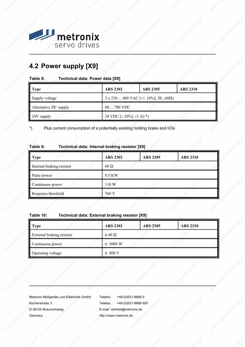
4.2 Power supply [X9]
Table 8: Technical data: Power data [X9]
Type ARS 2302 ARS 2305 ARS 2310
Supply voltage 3 x 230 ... 480 VAC [+/- 10%], 50...60Hz
Alternative DC supply 60 ... 700 VDC
24V supply 24 VDC [± 20%] (1 A) *)
*) Plus current consumption of a potentially existing holding brake and I/Os
Table 9: Technical data: Internal braking resistor [X9]
Type ARS 2302 ARS 2305 ARS 2310
Internal braking resistor 68 Ω
Pulse power 8.5 KW
Continuous power 110 W
Response threshold 760 V
Table 10: Technical data: External braking resistor [X9]
Type ARS 2302 ARS 2305 ARS 2310
External braking resistor ≥ 60 Ω
Continuous power ≤ 5000 W
Operating voltage ≥ 800 V
Metronix Meßgeräte und Elektronik GmbH Telefon: +49-(0)531-8668-0
Kocherstraße 3 Telefax: +49-(0)531-8668-555
D-38120 Braunschweig E-mail: [email protected]
Germany http://www.metronix.de

4.3 Motor connection [X6]
Table 11: Technical data: Motor connection data [X6]
Type ARS 2302 ARS 2305 ARS 2310
Data for use at 3x 400 VAC [± 10%], 50 Hz, with an output stage clock frequency of 5 kHz
Output power 1.5 kVA 3 kVA 6 kVA
Max. output power for 3 s 3 kVA 6 kVA 12 kVA
Output current 2.5 Aeff 5 Aeff 10 Aeff
Max. output current for 3 s 7.5 Aeff 15 Aeff 20 Aeff
Clock frequency 12.5 kHz max.
Max. mains current in continuous operation 1)
2.5 Aeff 5 Aeff 9 Aeff
1) for a cos ϕ of 0.7 in the motor circuit
4.3.1 ARS 2310 current derating
Other than stated in the technical motor data, the ARS 2310 servo positioning controller has current derating in nominal operating conditions. The following derating graph shows the admissible rated current as a function of the adjusted pulse frequency:
Metronix Meßgeräte und Elektronik GmbH Telefon: +49-(0)531-8668-0
Kocherstraße 3 Telefax: +49-(0)531-8668-555
D-38120 Braunschweig E-mail: [email protected]
Germany http://www.metronix.de

5 6 7 8 9 10 11 12 13
fPWM
[kHZ]1 2 3 4
1
2
3
4
5
6
7
8
9
10
I(fPWM)
[A]
Figure 2: ARS 2310 current derating graph
The following formula can be used to calculate the output current of the output stage as a function of the output stage frequency for values > 5 kHz:
I(fPWM) = 58
AkHZ fPWM 13,125 A
4.4 Angle encoder connection [X2A] and [X2B]
The universal rotary encoder interface allows several different feedback systems to be connected to the ARS 2300 servo positioning controller:
Resolvers (interface [X2A])
Encoders (interface [X2B])
Metronix Meßgeräte und Elektronik GmbH Telefon: +49-(0)531-8668-0
Kocherstraße 3 Telefax: +49-(0)531-8668-555
D-38120 Braunschweig E-mail: [email protected]
Germany http://www.metronix.de

Incremental encoders with analog and digital track signals
SinCos encoders (single-/multiturn) with HIPERFACE
Multiturn absolute value encoders with EnDat
The encoder type can be defined using the Metronix ServoCommander™ parameterisation software.
The feedback signal is made available to following drives via the incremental encoder output [X11].
It is possible to evaluate two rotary encoder systems in parallel. Normally, the resolver for current control is connected to [X2A] and, for example, an absolute value encoder to [X2B] as a feedback signal for position control.
4.4.1 Resolver connection [X2A]
The 9-pin D-SUB connection [X2A] is used to evaluate standard resolvers. Single- and multi-pole resolvers are supported. The user has to state the number of pairs of poles of the resolver in the "Motor Data" menu of the ServoCommander™ parameterisation program so that the ARS 2300 can determine the speed correctly. The number of pairs of poles of the motor (P0Motor) is always an integer multiple of the number of pairs of poles of the resolver (P0Resolver). Wrong combinations such as, for example, P0Resolver = 2 and P0Motor = 5 lead to an error message during motor identification.
The resolver offset angle, which is automatically determined during identification, is a read/write value for service purposes.
Table 12: Technical data: Resolver [X2A]
Parameter Value
Transformation ratio 0.5
Metronix Meßgeräte und Elektronik GmbH Telefon: +49-(0)531-8668-0
Kocherstraße 3 Telefax: +49-(0)531-8668-555
D-38120 Braunschweig E-mail: [email protected]
Germany http://www.metronix.de

Carrier frequency 5 to 10 kHz
Excitation voltage 7 Veff, short-circuit-proof
Excitation impedance (at 10 kHz) ≥ (20 + j20)Ω
Stator impedance ≤ (500 + j1000)Ω
Table 13: Technical data: Resolver interface [X2A]
Parameter Value
Resolution 16 bits
Signal detection delay < 200 µs
Speed resolution approx. 4 rpm
Absolute angle sensing accuracy < 5´
Max. speed 16,000 rpm
4.4.2 Encoder connection [X2B]
The 15-pin D-SUB connector [X2B] can be used to feed back motors equipped with an encoder. Possible incremental encoders for the encoder connection can be divided into several groups. If you have any queries concerning the use of other encoder types, please contact your distributor.
Standard incremental encoders without commutation signals <FW3.x>:
This encoder type is used in conjunction with low-cost linear motors to save the costs for provision of commutation signals (Hall generator). If such an encoder is used, the ARS 2300 servo positioning controller determines the pole position automatically after power-on.
Standard incremental encoders with commutation signals <FW3.x>:
In this variant, standard incremental encoders with three additional binary Hall generator signals are
Metronix Meßgeräte und Elektronik GmbH Telefon: +49-(0)531-8668-0
Kocherstraße 3 Telefax: +49-(0)531-8668-555
D-38120 Braunschweig E-mail: [email protected]
Germany http://www.metronix.de

used. The number of lines of the encoder can be parameterised as desired (1 - 16384 lines/revolution).
For the Hall generator signals, an additional offset angle applies. This angle is determined during motor identification or has to be set using the parameterisation software. Normally, the Hall generator offset angle is zero.
Stegmann encoders <FW3.x>:
Rotary encoders with HIPERFACE made by Stegman are supported in their single-turn or multi-turn variants. The following encoder models can be connected:
Single-turn SinCos encoders: SCS 60, SCS 70, SKS 36, SR 50, SR 60
Multi-turn SinCos encoders: SRM 50, SRM 60, SKM 36, SCM 60, SCM 70
SinCos encoders for hollow shaft drives: SCS-Kit 101, SCM-Kit 101, SHS 170
SinCoder® encoders like SNS50 or SNS60 are no longer supported.
Heidenhain encoders <FW3.x>:
The system can evaluate incremental and absolute encoders made by Heidenhain. The following encoder models can be connected:
Heidenhain ERN1085, ERN 1387, ECN1313, RCN220, RCN 723, RON786, ERO1285, etc.
Rotary encoders with an EnDat interface.
Table 14: Technical data: Encoder evaluation [X2B]
Parameter Value
Parameterisable number of encoder lines 1- 16384 lines/revolution
Angular resolution / interpolation 10 bits / period
Trace signals A, B 1 VSS differential
Trace signals N 0.2 to 1 VSS differential
Commutation track A1, B1 (optional) 1 VSS differential
Trace signal input impedance Differential input 120 Ω
Metronix Meßgeräte und Elektronik GmbH Telefon: +49-(0)531-8668-0
Kocherstraße 3 Telefax: +49-(0)531-8668-555
D-38120 Braunschweig E-mail: [email protected]
Germany http://www.metronix.de

Limit frequency flimit > 300 kHz (high-resolution track)flimit approx. 10 kHz (commutation track)
Additional communication interface EnDat (Heidenhain) and HIPERFACE (Stegmann)
Supply output 5 V or 12 V, 300 mA max., current-limitedControl through sensor linesSetpoint can be changed through SW
Metronix Meßgeräte und Elektronik GmbH Telefon: +49-(0)531-8668-0
Kocherstraße 3 Telefax: +49-(0)531-8668-555
D-38120 Braunschweig E-mail: [email protected]
Germany http://www.metronix.de

4.5 Communication interfaces
4.5.1 RS232 [X5]
Table 15: Technical data: RS232 [X5]
Communication interface Values
RS232 In accordance with RS232 specification, 9600 bauds to 115.2 kbauds
4.5.2 CAN bus [X4]
Table 16: Technical data: CAN bus [X4]
Communication interface Values
CANopen controller ISODIS 11898, Full-CAN-Controller, 1M baud max.
CANopen protocol In accordance with DS301 and DSP402
4.5.3 I/O interface [X1]
Table 17: Technical data: Digital inputs and outputs [X1]
Digital inputs / outputs Values
Signal level 24V (8V…30V) active high, compliant with EN 1131-2
Logic inputs in general DIN0 DIN1 DIN2 DIN3
Bit 0 \Bit 1, \ Target selection for positioningBit 2, / 16 targets can be selected from target tableBit 3 /
Metronix Meßgeräte und Elektronik GmbH Telefon: +49-(0)531-8668-0
Kocherstraße 3 Telefax: +49-(0)531-8668-555
D-38120 Braunschweig E-mail: [email protected]
Germany http://www.metronix.de

Digital inputs / outputs Values
DIN4 Control input for output stage enabling at high
DIN5 Controller enabled at high, fault acknowledgement at low
DIN6 Limit switch input 0
DIN7 Limit switch input 1
DIN8 Control signal for positioning start
DIN9 Home switch for homing or saving of positions
Metronix Meßgeräte und Elektronik GmbH Telefon: +49-(0)531-8668-0
Kocherstraße 3 Telefax: +49-(0)531-8668-555
D-38120 Braunschweig E-mail: [email protected]
Germany http://www.metronix.de

Logic outputs in general Electrically isolated, 24V (8V…30V) active high
DOUT0 Ready for operation 24 V, 100 mA max.
DOUT1 Freely configurable 24 V, 100 mA max.
DOUT2 Freely configurable, can also be used optionally as input DIN10
24 V, 100 mA max.
DOUT3 Freely configurable, can also be used optionally as input DIN11
24 V, 100 mA max.
DOUT4 [X6] Holding brake 24 V, 2 A max.
Table 18: Technical data: Analog inputs and outputs [X1]
Analog inputs / outputs Values
High-resolution analog input:AIN0
±10V input range, 16 bits, differential,< 250µs delay
Analog input:
AIN1
Optionally, this input can also be parameterised as digital input DIN AIN1 with a switching threshold of 8V
±10V, 10 bits, single-ended,< 250µs delay
Analog input:
AIN2
Optionally, this input can also be parameterised as digital input DIN AIN2 with a switching threshold of 8V
±10V, 10 bits, single-ended,< 250µs delay
Analog outputs:
AOUT0 and AOUT1
±10V output range, 9-bit resolution, flimit > 1kHz
4.5.4 Incremental encoder input [X10]
The input supports all commercially available incremental encoders.
For example encoders complying with industrial standard ROD426 made by Heidenhain or encoders with "single-ended" TTL outputs or "open collector" outputs.
Metronix Meßgeräte und Elektronik GmbH Telefon: +49-(0)531-8668-0
Kocherstraße 3 Telefax: +49-(0)531-8668-555
D-38120 Braunschweig E-mail: [email protected]
Germany http://www.metronix.de

As an alternative, the A and B trace signals of the device are interpreted as pulse direction signals so that the controller can also be controlled by stepper motor control cards.
Table 19: Technical data: Incremental encoder input [X10]
Parameter Value
Parameterisable line count 1 – 228 lines / revolution
Trace signals: A, #A, B, #B, N, #N In accordance with RS422 specification
Max. input frequency 1 MHz
Pulse direction interface: CLK, #CLK, DIR, #DIR, RESET, #RESET In accordance with RS422 specification
Supply output 5 V, 100 mA max.
4.5.5 Incremental encoder output [X11] <FW3.x>
The output supplies incremental encoder signals which can be processed in superimposed control systems.
The signals are generated on the basis of the angle of rotation of the encoder with a freely programmable number of lines.
In addition to trace signals A and B, the emulation also supplies a reset pulse. Once per revolution (for the programmed number of lines), this pulse assumes a high state for ¼ of a signal period (as long as trace signals A and B are high).
Metronix Meßgeräte und Elektronik GmbH Telefon: +49-(0)531-8668-0
Kocherstraße 3 Telefax: +49-(0)531-8668-555
D-38120 Braunschweig E-mail: [email protected]
Germany http://www.metronix.de

Table 20: Technical data: Incremental encoder output [X11]
Parameter Value
Number of output lines Programmable, 1 - 16384 lines / revolution
Connection level Differential / RS422 specification
Trace signals A, B, N In accordance with RS422 specification
Special feature N trace can be deactivated
Output impedance Ra,diff = 66 Ω
Limit frequency flimit > 1.8 MHz (lines/s)
Edge triggering (minimum pulse width) Can be limited through parameters
Supply output 5 V, 100 mA max.
Metronix Meßgeräte und Elektronik GmbH Telefon: +49-(0)531-8668-0
Kocherstraße 3 Telefax: +49-(0)531-8668-555
D-38120 Braunschweig E-mail: [email protected]
Germany http://www.metronix.de

5 Function overview
5.1 Motors
5.1.1 Synchronous servo motors
Typically, permanently excited synchronous motors with sinusoidal EMF are used. The ARS 2300 servo positioning controller is a universal servo drive controller which can be used in conjunction with standard servo motors. An automatic motor identification system determines and parameterises the motor data.
5.1.2 Linear motors
In addition to rotary applications, ARS 2300 servo positioning controllers are also suitable for linear drives. They support permanently excited synchronous linear motors. Due to their high signal processing quality - especially concerning encoder signals - and their high clock frequency, ARS 2000 servo positioning controllers are particularly suitable for controlling air-core and iron-core synchronous motors with a low motor inductance (2…4mH).
5.2 ARS 2300 servo positioning controller functions
5.2.1 Compatibility
For reasons of compatibility, the control structure of the ARS 2300 servo positioning controller has to a large extent the same characteristics, interfaces and parameters as the previous ARS product range.
Metronix Meßgeräte und Elektronik GmbH Telefon: +49-(0)531-8668-0
Kocherstraße 3 Telefax: +49-(0)531-8668-555
D-38120 Braunschweig E-mail: [email protected]
Germany http://www.metronix.de
PWM E1 E2M
Positioncontroller
Speed controller Currentcontroller
Outputstage Motor
Angleencoder 1
and 2
Actual value managementX2AX2BX10
Setpoint management- Analog inputs- Fixed values- Synchronisation- Ramp generator
Positioning and interpolationTrajectory calculation:- Position setpoint- Speed feedforward- Current feedforward
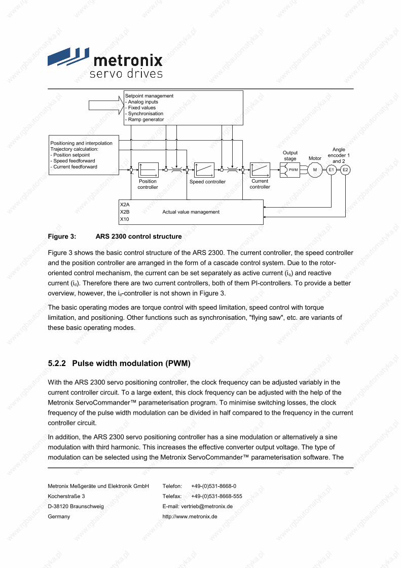
Figure 3: ARS 2300 control structure
Figure 3 shows the basic control structure of the ARS 2300. The current controller, the speed controller and the position controller are arranged in the form of a cascade control system. Due to the rotor-oriented control mechanism, the current can be set separately as active current (iq) and reactive current (id). Therefore there are two current controllers, both of them PI-controllers. To provide a better overview, however, the id-controller is not shown in Figure 3.
The basic operating modes are torque control with speed limitation, speed control with torque limitation, and positioning. Other functions such as synchronisation, "flying saw", etc. are variants of these basic operating modes.
5.2.2 Pulse width modulation (PWM)
With the ARS 2300 servo positioning controller, the clock frequency can be adjusted variably in the current controller circuit. To a large extent, this clock frequency can be adjusted with the help of the Metronix ServoCommander™ parameterisation program. To minimise switching losses, the clock frequency of the pulse width modulation can be divided in half compared to the frequency in the current controller circuit.
In addition, the ARS 2300 servo positioning controller has a sine modulation or alternatively a sine modulation with third harmonic. This increases the effective converter output voltage. The type of modulation can be selected using the Metronix ServoCommander™ parameterisation software. The
Metronix Meßgeräte und Elektronik GmbH Telefon: +49-(0)531-8668-0
Kocherstraße 3 Telefax: +49-(0)531-8668-555
D-38120 Braunschweig E-mail: [email protected]
Germany http://www.metronix.de

default setting is sine modulation.
Table 21: Output voltage at the motor terminals in the case of UZK = 560V
Converter output voltage Output voltage at the motor terminals
UA,(sin) ULL,motor = approx. 320 Veff
UA,(sin+sin3x) ULL,motor = approx. 360 Veff
5.2.3 Setpoint management
The setpoint for the torque and speed control modes can be set via a setpoint management system.
The following setpoint sources can be selected:
3 analog inputs:
AIN 0, AIN 1 and AIN 2
3 fixed values:
1st value: Setting depending on controller enabling logic:
Fixed value 1 or
RS232 interface or
CANopen bus interface or
PROFIBUS-DP interface or
SERCOS interface <FW3.x>
2nd and 3rd value: Setting of fixed values 2 and 3
Process controller <FW3.x>
SYNC input <FW3.x>
Additional incremental encoder input [X10]
If no setpoint source is active, the setpoint is zero.
Metronix Meßgeräte und Elektronik GmbH Telefon: +49-(0)531-8668-0
Kocherstraße 3 Telefax: +49-(0)531-8668-555
D-38120 Braunschweig E-mail: [email protected]
Germany http://www.metronix.de
The setpoint management system has a ramp generator with a preceding adder. Any of the above-mentioned setpoint sources can be selected using corresponding selectors and run through the ramp generator. Additional setpoint sources, which are not run through the ramp generator, can be selected with the help of two additional selectors. The total setpoint is a summation of all values. The acceleration and braking time of the ramp can be parameterised depending on the direction.
5.2.4 Torque-controlled mode
In torque-controlled mode, a certain torque is preset and generated in the motor by the servo controller. In this case, only the current controller is activated since the torque is proportional to the motor current.
5.2.5 Speed-controlled mode
This operating mode is used when the motor speed has to be kept constant regardless of the active load. The motor speed exactly follows the speed specified by the setpoint management system.
With the factory setting of the ARS 2300 servo positioning controller, the cycle time of the speed control circuit is twice the PWM period, thus typically 200µs. However, it can also be set as an integer multiple of the current controller cycle time.
The speed controller is a PI-controller and has an internal resolution of 12 bits per rpm. In order to eliminate wind-up effects, the integrator function is stopped when underlying limits are reached.
In speed control mode, the current controllers and the speed controller are active. If the setpoint is set via analog setpoint inputs, a "safe zero" can be defined as an option. If the analog setpoint is in this range, the setpoint is set to zero ("dead zone"). Thus interferences or offset drifts can be suppressed. The function of a dead zone can be activated and deactivated and its range can be adjusted.
The motor-internal encoder system, which is also used for commutation, determines the actual speed and the actual position. For the actual value feedback to the speed control system, all encoder interfaces can be equally selected (e.g. reference encoder or a corresponding system at the external incremental encoder input). The actual speed value for the speed controller can be fed back via the external incremental encoder input, for instance.
The speed setpoint can be set internally or derived from the data of an external encoder system (speed synchronisation via [X10] for the speed controller).
Metronix Meßgeräte und Elektronik GmbH Telefon: +49-(0)531-8668-0
Kocherstraße 3 Telefax: +49-(0)531-8668-555
D-38120 Braunschweig E-mail: [email protected]
Germany http://www.metronix.de

5.2.6 Torque-limited speed control
ARS 2300 servo positioning controllers support torque-limited speed-controlled operation with the following characteristic features:
Fast updating of the limit value, e.g. in a 200 µs cycle
Addition of two limitation sources (e.g. for feedforward values)
5.2.7 Synchronisation with external clock sources
The controllers operate with sinusoidal constrained current. The cycle time is always linked with the PWM frequency. In order to synchronise the device control system with external clock sources (e.g. SERCOS, PROFIBUS MC), the device is equipped with a corresponding PLL. In these cases, the cycle time is variable within certain limits in order to allow synchronisation with the external clock signal. For synchronisation with external clock sources, the user has to indicate the nominal synchronous cycle time.
5.2.8 Load torque compensation in the case of vertical axes
In the case of vertical-axis applications, the holding torque during standstill can be measured and saved. It is then used in the torque control circuit and improves the start-up behaviour of the axis after the holding brake has been released.
5.2.9 Positioning and position control
In positioning mode, a superordinate position controller is active in addition to the speed control. This position controller processes the deviation of the actual position from the set position and converts it into the corresponding setpoints for the speed controller.
The position controller is a P-controller. By default, the cycle time of the position control circuit is twice
Metronix Meßgeräte und Elektronik GmbH Telefon: +49-(0)531-8668-0
Kocherstraße 3 Telefax: +49-(0)531-8668-555
D-38120 Braunschweig E-mail: [email protected]
Germany http://www.metronix.de

the speed controller cycle time. However, it can also be set as an integer multiple of the speed controller cycle time.
When the position controller is activated, it receives its setpoints from the positioning or synchronisation controller. The internal resolution is up to 32 bits per motor revolution (depending on the encoders used).
5.2.10 Synchronisation, electrical transmission <FW3.x>
The ARS 2300 servo positioning controller can be used in a master-slave configuration hereinafter called synchronisation. The controller can be a master or a slave.
If the ARS 2300 servo positioning controller is used as a master, it can supply the slave with its current rotor position via the incremental encoder output [X11]. If the ARS 2300 servo positioning controller (used as a master) is equipped with a communication interface, it can transmit either its current position, speed or both values.
If the ARS 2300 servo positioning controller is used as a slave, several inputs are available for synchronisation. An incremental encoder (position synchronisation via [X10] with speed feedforward for the speed controller) or the communication interface can be used as inputs. The ARS 2300 servo positioning controller can automatically calculate the speed feedforward. All inputs can be activated/deactivated. The internal encoder can be deactivated if another input is selected as actual value encoder. This also applies to the speed control mode. The external inputs can be weighed with transmission factors. The inputs can be used individually or simultaneously.
5.2.11 Brake management
The ARS 2300 servo positioning controller can directly control a holding brake. The holding brake is actuated with programmable delays. In positioning mode, an additional automatic braking function can be activated, which shuts down the power stage of the ARS 2300 servo positioning controller after a parameterised idle time and lets the brake fall in. This mode of operation is compatible with the functions of the previous ARS product range.
Metronix Meßgeräte und Elektronik GmbH Telefon: +49-(0)531-8668-0
Kocherstraße 3 Telefax: +49-(0)531-8668-555
D-38120 Braunschweig E-mail: [email protected]
Germany http://www.metronix.de

5.3 Positioning control
5.3.1 Overview
In positioning mode, a certain position is set and the motor has to move to this position. The current position is determined using the information of the internal encoder evaluation. The position deviation is processed in the position controller and passed on to the speed controller.
The integrated positioning control system allows jerk-limited or time-optimal positioning, either relative or absolute with regard to a reference point. It provides the position controller and - to improve the dynamic behaviour - also the speed controller with setpoints.
During absolute positioning, a predefined target position is directly approached. During relative positioning, the parameterised route is travelled. The positioning range of 232 full revolutions allows any number of relative positioning runs in one direction.
The positioning control system is parameterised using a target table. This table includes entries for the parameterisation of a target via a communication interface and also target positions which can be retrieved via the digital inputs. For each entry it is possible to set the positioning mode, the driving profile, the acceleration and deceleration times and the maximum speed. All targets can be pre-parameterised. All the user has to do during positioning is to select the desired entry and to give out a start command. However, the target parameters can also be changed online via the communication interface.The maximum number of storable position sets is 256 in the case of the ARS 2300 servo positioning controller.
The following settings can be made for all position sets:
Target position
Driving speed
Final speed
Acceleration
Deceleration
Metronix Meßgeräte und Elektronik GmbH Telefon: +49-(0)531-8668-0
Kocherstraße 3 Telefax: +49-(0)531-8668-555
D-38120 Braunschweig E-mail: [email protected]
Germany http://www.metronix.de

Torque feedforward
Remaining distance message
Additional flags:
Relative / relative to last target / absolute
Wait for end / interrupt / ignore start
Synchronised
Rotary axis: Fixed direction of motion <FW3.x>
Option: Automatic braking if there is no follow-up positioning run
Option: The driving speed can be changed continuously via an analog input in the course of the motion task <FW3.x>.
Several options for setting up path programs
The positioning sets can be addressed through all bus systems or using the Metronix ServoCommander™ parameterisation software. The positioning process can be controlled via the digital inputs.
5.3.2 Relative positioning
In the case of relative positioning, the target position is added to the current position. As this does not require a fixed zero point, referencing is not compulsory. It does, however, make sense in many cases in order to bring the drive to a defined position.
When several relative positioning sequences are added, e.g. for a trimming unit or a conveyor belt, endless positioning in one direction is possible (incremental dimension).
5.3.3 Absolute positioning
The position target is approached regardless of the current position. We recommend referencing the drive for absolute positioning. In the case of absolute positioning, the target position is a fixed (absolute) position with regard to the zero point or reference point.
Metronix Meßgeräte und Elektronik GmbH Telefon: +49-(0)531-8668-0
Kocherstraße 3 Telefax: +49-(0)531-8668-555
D-38120 Braunschweig E-mail: [email protected]
Germany http://www.metronix.de

5.3.4 Driving profile generator
Driving profiles can be divided into time-optimal and jerk-limited positioning profiles. For time-optimal positioning, the systems starts and stops with maximum predefined acceleration. The drive reaches the target in the shortest possible time. The velocity profile is trapezoidal while the acceleration profile is block-shaped. During jerk-limited positioning, the acceleration profile is trapezoidal and the velocity profile is therefore of third order. Since the acceleration changes steadily, the drive moves particularly gently with regard to the mechanical system.
a(t) a(t) a(t)
t t t
v(t)
t
v(t)
t
v(t)
t
time-optimal jerk-limited jerk-limited
Figure 4: ARS 2300 servo positioning controller driving profiles
5.3.5 Homing
At start-up, every positioning control needs a defined zero point which is determined by means of a home run. The ARS 2300 servo positioning controller can perform this home run automatically. It evaluates several inputs, e.g. the limit switch inputs, as reference signal.
Homing can be started following a command via the communication interface or automatically when the controller is enabled. Optionally, the start can also be configured via a digital input using the Metronix ServoCommander™ parameterisation software to be able to perform a home run in a targeted manner regardless of the controller enabling. The controller enabling acknowledges error messages, for example, and can be switched off depending on the application, without requiring another home run when the controller is enabled again. As the existing digital inputs are all occupied in standard applications, the analog inputs AIN1 and AIN2 can optionally be used as digital inputs DIN
Metronix Meßgeräte und Elektronik GmbH Telefon: +49-(0)531-8668-0
Kocherstraße 3 Telefax: +49-(0)531-8668-555
D-38120 Braunschweig E-mail: [email protected]
Germany http://www.metronix.de

AIN1 and DIN AIN2, and the digital outputs DOUT2 and DOUT3 as digital inputs DIN10 and DIN11.
For homing, several methods have been implemented following the DSP 402 CANopen protocol. Usually, the system starts by looking for a switch at search speed. The subsequent motion depends on the method and type of communication. If homing is activated via the field bus, there is no follow-up positioning run up to the zero position. This can be done optionally when the system is started through controller enabling or RS232. A follow-up positioning run is always possible as an option. The default setting is "no follow-up positioning run".
Ramps and speeds can be parameterised for homing. Homing can also be performed in a time-optimal or jerk-free manner.
5.3.6 Positioning sequences
Positioning sequences consist of series of position sets. These are performed one after the other. Due to its path program options, a position set can become part of a path program. The result is an interlinked list of positions:
POS1POS13
POS19
START
END
POS5 POS6POS7 POS8
Figure 5: Path program
Using the start position of the path program, the user defines the position sequence to be performed. In principle, linear or cyclic sequences are possible. The end of a position sequence is indicated by setting the next sequential position to an "impossible" value (e.g. - 1).
The start position of a path program can be determined:
via field bus
Metronix Meßgeräte und Elektronik GmbH Telefon: +49-(0)531-8668-0
Kocherstraße 3 Telefax: +49-(0)531-8668-555
D-38120 Braunschweig E-mail: [email protected]
Germany http://www.metronix.de
via digital inputs
The number of positions in a positioning sequence is only limited by the number of total positions available.
Any position set can be used in a path program. The following adjustments can be made for the position sets:
Follow-up position number for two successors (several successors are possible if forwarding is done via digital inputs)
Start-up delay
Waiting for forwarding via digital inputs at the end of the positioning run
Flag: Never stop at this position when then path program is aborted
Set the digital output when the target position has been reached / position started
Further information can be found in the "Servo positioning controller ARS 2000" software manual.
5.3.7 Stop input in the positioning mode
The stop input can interrupt the running positioning process by setting the adjusted digital input. When the input is reset, the positioning process continues to approach to original target position. Since the existing digital inputs are usually occupied by standard applications, the analog inputs AIN1 and AIN2 as well as the digital outputs DOUT2 and DOUT3, which can also be used as digital inputs, can be used as an option.
5.3.8 Continuous-path control with linear interpolation
Due to the implementation of the ,interpolated position mode’, position setpoints can be set for multi-axis use of the controller. In this mode, position setpoints are specified by a subordinated control at fixed intervals (synchronisation intervals). If the interval is greater than a position controller cycle, the controller automatically interpolates the data values between two specified position values as shown in the following graph. In addition, the servo positioning controller also calculates a corresponding speed feedforward.
Metronix Meßgeräte und Elektronik GmbH Telefon: +49-(0)531-8668-0
Kocherstraße 3 Telefax: +49-(0)531-8668-555
D-38120 Braunschweig E-mail: [email protected]
Germany http://www.metronix.de
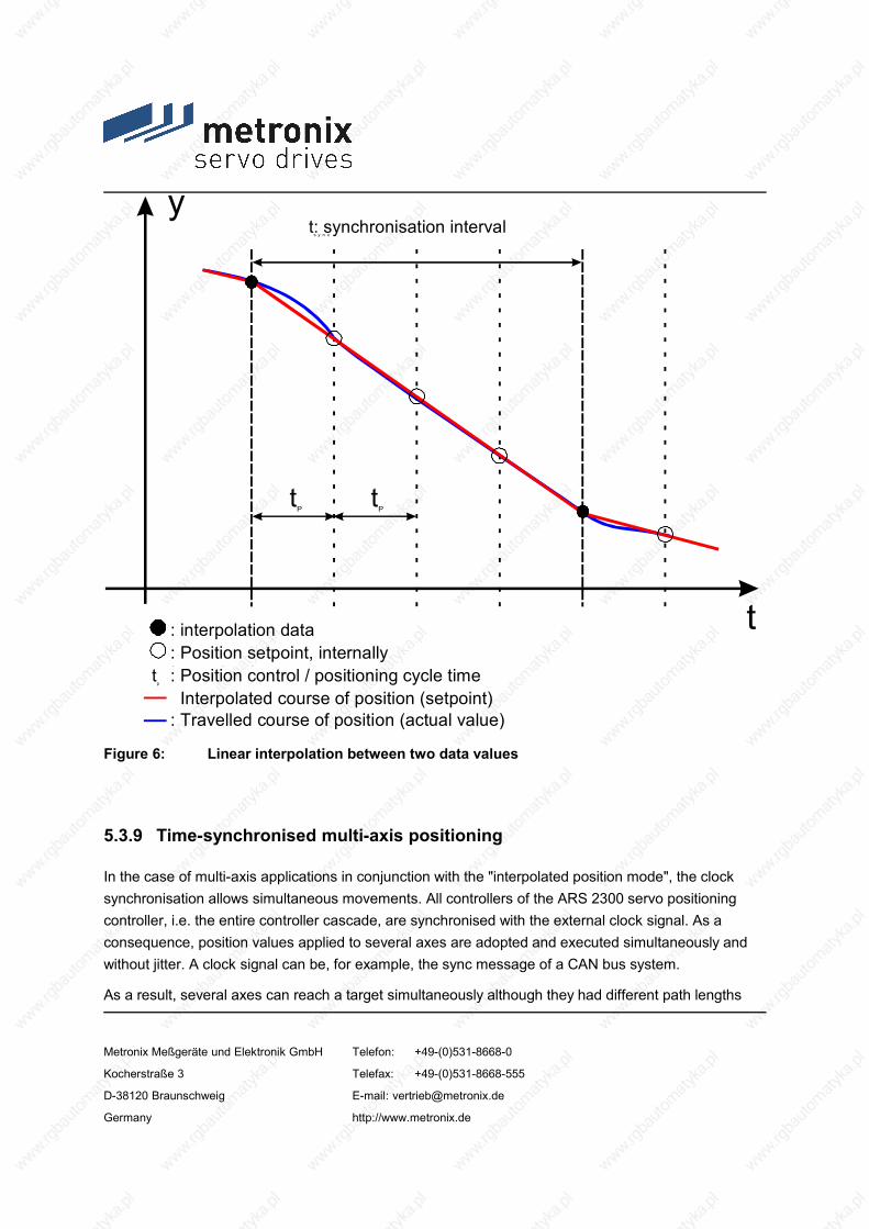
y
t
t: synchronisation interval s y n c
t P t
P
: Position setpoint, internally interpolated
: interpolation data
: Position control / positioning cycle time Interpolated course of position (setpoint) : Travelled course of position (actual value)
t p
Figure 6: Linear interpolation between two data values
5.3.9 Time-synchronised multi-axis positioning
In the case of multi-axis applications in conjunction with the "interpolated position mode", the clock synchronisation allows simultaneous movements. All controllers of the ARS 2300 servo positioning controller, i.e. the entire controller cascade, are synchronised with the external clock signal. As a consequence, position values applied to several axes are adopted and executed simultaneously and without jitter. A clock signal can be, for example, the sync message of a CAN bus system.
As a result, several axes can reach a target simultaneously although they had different path lengths
Metronix Meßgeräte und Elektronik GmbH Telefon: +49-(0)531-8668-0
Kocherstraße 3 Telefax: +49-(0)531-8668-555
D-38120 Braunschweig E-mail: [email protected]
Germany http://www.metronix.de

and traversing speeds.
Metronix Meßgeräte und Elektronik GmbH Telefon: +49-(0)531-8668-0
Kocherstraße 3 Telefax: +49-(0)531-8668-555
D-38120 Braunschweig E-mail: [email protected]
Germany http://www.metronix.de

6 Functional safety technology
6.1 General, intended use
The ARS 2300 servo positioning controllers support the “Save Torque-Off" safety function with prevention of “unexpected start-up” and “switch to powerless” as required by standard EN ISO 13849-1, Performance Level d.
Statistical Data:
Channel 1, switch off the PWM signal via X1 : MTTFd = 714,81 years
Channel 2, switch off the power supply to the six output stage IGTBs via X3 : MTTFd = 304,7 years
PFH value : PFH = 8,63 • 10-8 /h
The MTTFd values are therefore limited to 100 years ("high").
Note:
The characteristic values are valid only at use as agreed after product manual
These are calculated values which represent the probabilities of failure. They do not guarantee any particular product lifecycle
According to EN ISO 13849-1: 2008-12, section „C.5 MTTFd data of electrical components“ can be accepted that only 50% of the failures lead to dangerous failures
The standstill of the machine has to be initiated and ensured by the control system of the machine. For vertical axes, safety precautions are to be urgently needed.
This applies particularly to vertical axes without self-locking mechanism or weight compensation.
In accordance with a danger analysis / risk assessment following the machinery directives 2006/42/EG and the appropriate standardize respectively, the machine manufacturer has to plan the safety system for the entire machine whilst taking into account all components integrated. Among these are also electric drives. The requirement at controls, i.e. the performance level which can be selected results from the risk height (see).
Metronix Meßgeräte und Elektronik GmbH Telefon: +49-(0)531-8668-0
Kocherstraße 3 Telefax: +49-(0)531-8668-555
D-38120 Braunschweig E-mail: [email protected]
Germany http://www.metronix.de

The “Safe Torque-Off (STO)” function will not cause an electrical isolation. It therefore provides no protection against electric shock. It is thus impossible to achieve an EMERGENCY OFF in the normative sense by using the "Safe Torque-Off (STO)" function, because in order to do so, the entire system would have to be shut down via the power switch (main switch or power contactor).
There are three stop categories for an EMERGENCY STOP as per EN 60204-1 which can be used depending on a risk analysis (see Table 22).
Table 22: Stop categories
Stop category 0
Uncontrolled stop. Standstill by immediate disconnection from power.
EMERGENCY OFF or EMERGENCY STOP
Stop category 1
Controlled stop. Power is disconnected when the machine has come to a standstill.
EMERGENCY STOP
Stop category 2
Controlled stop. Power is not disconnected when the machine is at a standstill.
not suitable for EMERGENCY OFF or EMERGENCY STOP
6.2 Integrated "Safe torque-Off (STO)" functionThe “Safe Torque-Off” function does not protect against electrical shock. It only offers protection against dangerous rotary motion!
6.2.1 General / description of "Safe Torque-Off" function
The “Safe Torque-Off” function, in former times “safe stop”, safely interrupts the power supply to the drive. The drive may not generate any torque and therefore no dangerous rotary motion. In the case of hanging loads additional measures must be taken to safely prevent sagging (e.g. mechanical holding brake). In “Safe Torque-Off” mode, the standstill position does not have to be monitored.
Metronix Meßgeräte und Elektronik GmbH Telefon: +49-(0)531-8668-0
Kocherstraße 3 Telefax: +49-(0)531-8668-555
D-38120 Braunschweig E-mail: [email protected]
Germany http://www.metronix.de

There are basically three suitable measures to bring about a “Safe Torque-Off”:
contactor between mains and drive system (power contactor)
contactor between power section and drive motor (motor contactor)
safe pulse inhibitor (inhibiting of pulses form power semiconductor, integrated into ARS 2300)
The use of the integrated solution (safe pulse inhibitor) offers several advantages:
less external components, e.g. contactors
less wiring and space needed in switch cabinet
lower cost
Another advantage is the availability of the system. With the integrated solution the intermediate circuit of the servo controller can remain loaded. As a consequence, there are no significant waiting times for a system restart.
Metronix Meßgeräte und Elektronik GmbH Telefon: +49-(0)531-8668-0
Kocherstraße 3 Telefax: +49-(0)531-8668-555
D-38120 Braunschweig E-mail: [email protected]
Germany http://www.metronix.de

µP SM
X3
m on itoringof the
dri ver supp ly
X1
6 6 6 3
Holding brake (optional)
1
2
6
5
4
3
24V internal 15V IGTB driver supplyTriggering of driver supply relay(driver supply sw itch off)High = driver supply voltage"ON"Low = "pulse inhibitor" active
"Locking" of holding brake in case oftriggeringDriver supply relay = low
IGBT output stage
Output stage driver
PWM signal inhibition
Con
trolle
r ena
blin
g D
IN5
Out
put s
tage
ena
blin
g D
IN4
Internal outputstage enabling
Triggering of holding brakeHigh = lift brake (active)Low = apply brake
9
21
1. shut-down path
2. shut-down pathFloating feedbackcontact for driver
supply
X6
2
1
7,8,9
+24V-IO
Figure 7: Block diagram “Safe Torque-Off” as per EN ISO 13849-1, Performance Level d
If the “Safe Torque-Off” function is not needed, bridge pins 1 and 2 to [X3].
A “Safe Torque-Off” as per EN ISO 13849-1, Performance Level d, requires two channels, i.e. a restart must be safely prevented two ways, completely independent of each other. These two ways of interruption, the power supply to the drive and the safe pulse inhibitor, are called shut-down paths.
1. Shut-down path:
Metronix Meßgeräte und Elektronik GmbH Telefon: +49-(0)531-8668-0
Kocherstraße 3 Telefax: +49-(0)531-8668-555
D-38120 Braunschweig E-mail: [email protected]
Germany http://www.metronix.de

Output stage enabling via [X1] (inhibition of PWM signals; die IGBT drivers will no longer be addressed with modulation patterns).
2. Shut-down path:
Interruption of power supply to the six output stage IGTBs via [X3] by means of a relay (relays will cut the power supply to the IGBT optocoupler drivers to prevent PWM signals from getting to the IGBTs.).
Between the triggering of the output stage supply relay and the monitoring of the driver supply a plausibility test will be performed in the µP. This will detect errors in the pulse inhibitor and will also suppress the error message E-05-2 ("Driver voltage fault") occurring during normal operation.
3. Floating feedback contact:
The integrated circuit for the “Safe Torque-Off” function also has a floating feedback contact ([X3] pins 5 and 6) for the existence of the driver supply. This contact is designed as a normally closed contact. It, for example, has to be connected to the superordinate control. At regular intervals (e.g. PLC cycle or with each “Safe Torque-Off” request), the PLC has to perform a plausibility check between the triggering of the driver supply relay and the feedback contact (contact open = driver supply available).
In the case of an error during the plausibility check, further operation must be prevented, e.g. by eliminating the controller enabling or by shutting down the power contactor.
6.2.2 Safe holding brake activation
In the case of activation of the "Safe Torque-Off" function, the holding brake is switched currentless (brake applied); (see block diagram).
1st Channel:
During operation the holding brake is controlled with the DIN5 (controller enabling) (see timing diagram below). The first shut-down path “output stage enabling” acts on the brake driver via the µP and switches the holding brake currentless (brake applied).
2nd Channel:
The second shut-down path “triggering of driver supply relay” directly acts on s MOSFET which deactivates the holding brake (brake applied).
Metronix Meßgeräte und Elektronik GmbH Telefon: +49-(0)531-8668-0
Kocherstraße 3 Telefax: +49-(0)531-8668-555
D-38120 Braunschweig E-mail: [email protected]
Germany http://www.metronix.de

The user is responsible for the dimensioning and the safe functioning of the holding brake. The functioning of the brake must be checked and ensured by means of a suitable brake test.
Metronix Meßgeräte und Elektronik GmbH Telefon: +49-(0)531-8668-0
Kocherstraße 3 Telefax: +49-(0)531-8668-555
D-38120 Braunschweig E-mail: [email protected]
Germany http://www.metronix.de

6.2.3 Mode of operation / timing:
The following timing diagram shows how the "Safe Torque-Off" function works in connection with the controller enabling and the holding brake:
Metronix Meßgeräte und Elektronik GmbH Telefon: +49-(0)531-8668-0
Kocherstraße 3 Telefax: +49-(0)531-8668-555
D-38120 Braunschweig E-mail: [email protected]
Germany http://www.metronix.de

t1 t2 t3 t5 t6 t7 t8 t10 t11 t12 t13t9t4t
t
t
t
t
t
t
t
t
Triggering of pulse am plifie r supply re lay (optocouple r dr iver)X3.2 (24V)
X3.2 (0V)Supply of pulse am plifiers (optocouplerdriver)“ON“
(15V)
“OFF”
Floating feedback contact for driversupply (X3.5/6)open
closed
Output s tage enabling (X1, DIN4)“ON”
Timing of outputstage enabling
variable
Controller enabling (X1, DIN5)
Ansteuerung Haltebrem se(X6.1/2)gelös t
(24V)
fest(0V)
Internal output stage enabling(controlled by µP)
Set speed "n"
n=0
n
“H”“H”
“H”
Seven-segm entdisplay
Delay until brake isre leased!
Delay until brake isapplied!
Tim ing of "Safe Torque-Off"activation variable .To be determ ined by user,e .g. by m eans of safe tysw itching devices,depending on application.
2. shut-down path
1. shut-down path
Discharge curve ofe lectrolytic capacitors forthe supply of the pulseam plifiers
"Safe Torque-Off""Safe Torque-Off"
“OFF”
“ON”
“OFF”
Can be se t via Metronix ServoCom m ander TM
Both ram ps ca be setseparate ly via
MetronixServoCom m ander TM
Metronix Meßgeräte und Elektronik GmbH Telefon: +49-(0)531-8668-0
Kocherstraße 3 Telefax: +49-(0)531-8668-555
D-38120 Braunschweig E-mail: [email protected]
Germany http://www.metronix.de

Figure 8: Timing of “Safe Torque-Off” as per EN ISO 13849-1, Performance Level d
Metronix Meßgeräte und Elektronik GmbH Telefon: +49-(0)531-8668-0
Kocherstraße 3 Telefax: +49-(0)531-8668-555
D-38120 Braunschweig E-mail: [email protected]
Germany http://www.metronix.de

Description of the timing diagram:
This timing diagram has been generated using as an example the speed control under consideration of the controller enabling DIN 5 at [X1]. For applications with field buses the controller enabling is also controlled by the respective field bus. Depending on the application, the mode of operation can be parameterized via Metronix ServoCommander™.
Note:In contrast to the functional operation, the “Safe Torque-Off” mode is marked in BOLD!
Initial state:
The 24V supply is switched on and the intermediate circuit has been loaded.
The servo controller is in “Safe Torque-Off” mode. This status is indicated by a flashing “H” on the 7-segment display.
In order to reactivate the output stage of the servo controller and thus to operate the connected motor, the following steps must be followed:
1. The triggering of the relay that switches the supply voltage of the output stage drivers (2nd shut-off path) happens at the time t1 via [X3] with 24V between pins 2 and 3.
2. The driver supply is charged.
3. The floating feedback contact ([X3] pins 5 and 6) for the plausibility check between the triggering of the driver supply relay and the availability of the driver supply is opened no later than 20ms after t1 (t2-t1).
4. Approx. 10ms after the opening of the feedback contact the “H” will disappear from the display at the time t3.
5. The time for the output stage enabling ([X1], DIN4) can for the most part be freely selected (t4-t1): The enabling may be at the same time as the triggering of the driver relay, but must happen approx. 10µs (t5-t4) prior to the rising edge of the controller enabling ([X1], DIN5), depending on the application.
6. With the rising edge of the controller enabling at the time t5 the release of the holding brake of the motor (if available) will be initiated and the output stage will be internally enabled. Releasing the brake is only possible if the triggering of the relay that switches the driver supply
Metronix Meßgeräte und Elektronik GmbH Telefon: +49-(0)531-8668-0
Kocherstraße 3 Telefax: +49-(0)531-8668-555
D-38120 Braunschweig E-mail: [email protected]
Germany http://www.metronix.de

is pending, since this will trigger a MOSFET, which is located in the circuit of the holding brake. The parameterization program Metronix ServoCommander™ can be used to set a delay (t6-t5). That way the drive will remain at “0” speed for the time set and only after this time has run out at t6, the drive will start approaching the set speed. This delay is set so that the existing holding brake is safely released before the rotary motion starts. For motors without holding brake this time can be set to 0.
7. At the time t7 the drive will have reached the set speed. The necessary ramp settings can be parameterized via Metronix ServoCommander™.
The following steps show how to get a rotating drive to a “Safe Torque-Off”:
1. Before activating the “Safe Torque-Off” (i.e. driver supply relay “OFF” and output stage enabling “OFF”; both shut-down paths inhibit the PWM signals) the drive should be stopped by deactivating the controller enabling. Depending on the application, the brake ramp (t9-t8) can be set via Metronix ServoCommander™ (“Quick stop deceleration”).
Activation of the “Safe Torque-Off” function during operation will cause the drive to run down. If the drive has a holding brake it will be activated. It is therefore very important to make sure that the motor brake can actually stop the motion of the drive.
2. After 0 speed has been reached, the drive will be controlled to this set value for a parameterizable drop-out delay time (t10-t9). This parameterizable time is the deceleration, at which the holding brake of the motor is applied. This time depends on the holding brake and must be set by the user. For applications without holding brake this time can be set to 0.
3. After this time has run out, the internal output stage enabling will be switched off by the µP (t10).
The holding brake will definitely be activated as soon as the “brake ramp time + set drop-out delay time” has run out, even if it the drive has not yet been able to stop!
4. As of t10 the “Safe Torque-Off” can be activated (simultaneous deactivation of triggering of driver supply relay and output stage enabling). The time (t11-t10) depends on the application and must be set by the user.
5. With the withdrawal of the trigger signal for the relay that switches off the driver supply (t11) the capacitors in this voltage branch will be discharged. Approx. 80ms (t12-t11) after
Metronix Meßgeräte und Elektronik GmbH Telefon: +49-(0)531-8668-0
Kocherstraße 3 Telefax: +49-(0)531-8668-555
D-38120 Braunschweig E-mail: [email protected]
Germany http://www.metronix.de

the withdrawal of the trigger signal for the relay that switches off the driver supply, the feedback contact ([X3], pins 5 and 6) will be closed.
6. At the time t13 the letter “H” will be shown on the 7-segment display of the servo controller for the visualization of the “Safe Torque-Off” function. This will happen no later than 30ms after the closing of the floating feedback contact (t13-12).
Metronix Meßgeräte und Elektronik GmbH Telefon: +49-(0)531-8668-0
Kocherstraße 3 Telefax: +49-(0)531-8668-555
D-38120 Braunschweig E-mail: [email protected]
Germany http://www.metronix.de

6.2.4 Application examples
6.2.4.1 Emergency stop circuit:
Metronix Meßgeräte und Elektronik GmbH Telefon: +49-(0)531-8668-0
Kocherstraße 3 Telefax: +49-(0)531-8668-555
D-38120 Braunschweig E-mail: [email protected]
Germany http://www.metronix.de

Inputs Outputs
PLC
+24V+24V
+24V
0V
0V
Driver supply ofoutput stage
0V
[X3] SAFE STANDSTILL
[X1] I/O communication
Mains input
24V Input
24V Output (optional)
µP
1
2
3
4
5
6
Triggering of relay
ERR (not used)
NC1
NC2
Con
trolle
r ena
blin
g
Out
put s
tage
driv
er su
pply
Powercontactor
L1
L2
L3
DIN5: Controller enabling
DIN4: Output stage enabling
ARS 2302 - ARS 2310
K1
EMERGENCYSTOP request
EMERGENCY STOPrequested
21
9
1
2
3
10
11
Feed
back
driv
er su
pply
Out
put s
tage
enab
ling
[X9.] Power supply
safety switchingdevice
DIN EN ISO 13849-1,Performance Level d
Drawn contactposition:EMERGENCYSTOP requested orsupply voltageswitched off
Figure 9: Emergency-off circuit in accordance with EN ISO 13849-1, Performance Level d, and stop category 0 in accordance with 60204-1.
Metronix Meßgeräte und Elektronik GmbH Telefon: +49-(0)531-8668-0
Kocherstraße 3 Telefax: +49-(0)531-8668-555
D-38120 Braunschweig E-mail: [email protected]
Germany http://www.metronix.de

Mode of operation:
The EMERGENCY STOP request inhibits the output stage enabling and the triggering of the relay for the driver supply of the IGBT output stage via the EMERGENCY STOP contactor. The drive coasts down and at the same time the holding brake of the motor, if available, is activated.
The servo controller is in “Safe Torque-Off” mode.
The EMERGENCY STOP contactor has been approved as per EN ISO 13849-1, Performance Level d.
A superordinate control monitors the “EMERGENCY STOP request” and “driver supply feedback” signals and checks them for plausibility. In the case of an error the power contactor will be shut down.
The DC-link voltage remains present and can be used by the drive immediately after deactivation of the EMERGENCY-STOP switching device and after the enabling of the controller.
The connection of the motor and the optional holding brake are not shown here, please refer to chapter 8 Electrical installation.
The brake of the motor has to be designed such that it can stop the movement of the drive.
Metronix Meßgeräte und Elektronik GmbH Telefon: +49-(0)531-8668-0
Kocherstraße 3 Telefax: +49-(0)531-8668-555
D-38120 Braunschweig E-mail: [email protected]
Germany http://www.metronix.de

6.2.4.2 Safety door monitoring
Metronix Meßgeräte und Elektronik GmbH Telefon: +49-(0)531-8668-0
Kocherstraße 3 Telefax: +49-(0)531-8668-555
D-38120 Braunschweig E-mail: [email protected]
Germany http://www.metronix.de

Inputs Outputs
PLC
+24V+24V
+24V
0V
0V
Powercontactor
L1
L2
L3
K1Safety door open
Request for standstill as per EN 60204-1 (stop category 1)
Safety door monitor
Feed
back
driv
er su
pply
Con
trolle
r ena
blin
g
Out
put s
tage
driv
er su
pply
Out
put s
tage
enab
ling
Driver supply ofoutput stage
0V
[X3] SAFE STANDSTILL
[X1] I/O communication
Mains input
24V Input
24V Output (optional)
µP
1
2
3
4
5
6
Triggering of relay
ERR (not used)
NC1
NC2
DIN5: Controller enabling
DIN4: Output stage enabling
ARS 2302 - ARS 2310
21
9
1
2
3
10
11
[X9.] Power supply
open
closed
Drawn contactposition:Safety door openor supply voltageswitched off
safety switchingdevice
DIN EN ISO 13849-1,Performance Level d
Figure 10: Safety door monitoring in accordance with EN ISO 13849-1, Performance Level
Metronix Meßgeräte und Elektronik GmbH Telefon: +49-(0)531-8668-0
Kocherstraße 3 Telefax: +49-(0)531-8668-555
D-38120 Braunschweig E-mail: [email protected]
Germany http://www.metronix.de

d, and stop category 1 in accordance with 60204-1.
Metronix Meßgeräte und Elektronik GmbH Telefon: +49-(0)531-8668-0
Kocherstraße 3 Telefax: +49-(0)531-8668-555
D-38120 Braunschweig E-mail: [email protected]
Germany http://www.metronix.de

Mode of operation:
The request to stop the drive will set the controller enabling to low.
The drive will approach 0 speed using the set deceleration ramp (parameterizable via Metronix ServoCommander™).
After the ramp time (including drop-out delay time of holding brake, if available) has run out, the triggering of the driver supply relay and the controller enabling will be cancelled by the superordinate control.
A superordinate control monitors the “safety door open”, “output stage driver supply output" and the “driver supply feedback” signals and checks them for plausibility. In the case of an error the power contactor will be shut down.
The opening of the safety door will also interrupt the output stage enabling and the triggering of the driver supply relay. The servo controller is in “Safe Torque-Off” mode and protected against restart.
The safety door switching device has been approved as per EN ISO 13849-1, Performance Level d.
The DC-link voltage remains present and can be used by the drive immediately after the safety door has been closed.
If the safety door is opened without a request for a standstill, the motor coasts down as per EN 60204-1 stop category 0 and at the same time the holding brake of the motor will be applied, if available. The drive is in “Safe Torque-Off” mode and protected against restart.
It is also possible to use a door position switch, which keeps the safety door closed until the drive has come to a complete standstill or the “feedback driver supply” signal indicates the safe mode and the plausibility check have been successfully completed. However, the “Safe Torque-Off” mode offering protection against restarting is only activated with the opening of the safety door (nor shown).
Another possible application is the use of a safety door switching device with delayed contacts. The opening of the safety door has a direct impact on the controller enabling, whose falling edge causes a controlled stopping at a set deceleration ramp. The signals “output stage enabling” and output stage driver supply” are then switched off with a delay via the safety module. The drop-out delay time must be matched to the deceleration ramp time (not shown).
The brake of the motor has to be designed such that it can stop the movement of the drive.
Metronix Meßgeräte und Elektronik GmbH Telefon: +49-(0)531-8668-0
Kocherstraße 3 Telefax: +49-(0)531-8668-555
D-38120 Braunschweig E-mail: [email protected]
Germany http://www.metronix.de

Metronix Meßgeräte und Elektronik GmbH Telefon: +49-(0)531-8668-0
Kocherstraße 3 Telefax: +49-(0)531-8668-555
D-38120 Braunschweig E-mail: [email protected]
Germany http://www.metronix.de

7 Mechanical installation
7.1 Important notes
Only use the servo positioning controller ARS 2302, ARS 2305 and ARS 2310 as a cabinet device for control cabinet installation.
Vertical mounting position with supply lines [X9] on top.
Mount to control cabinet plate using the fastening strap.
Installation spaces:Keep a minimum distance of 100 mm underneath and above the device to other components to ensure sufficient ventilation.A free installation space of 150 mm is recommended to ensure optimum wiring of the motor cable or of the angle encoder cable on the underside of the device.
The servo positioning controllers ARS 2302, ARS 2305 and ARS 2310 may be installed directly next to one another on a heat-dissipating back plate provided that they are installed properly and used as intended. Please note that excessive heating may cause premature aging and/or damaging of the device. In case of high thermal stress, a mounting distance of 75 mm between the servo positioning controllers of type ARS 2302, ARS 2305 and ARS 2310 is recommended.
The connections of the following illustrations of the ARS 2310 servo positioning controller also apply to servo positioning controller ARS 2305 and ARS 2302!
Metronix Meßgeräte und Elektronik GmbH Telefon: +49-(0)531-8668-0
Kocherstraße 3 Telefax: +49-(0)531-8668-555
D-38120 Braunschweig E-mail: [email protected]
Germany http://www.metronix.de

100 mm of free installation space to ensure sufficient ventilationof servo positioning controller ARS 2302, 2305 and 231010
0 m
m.
100 mm of free installation space to ensure sufficient ventilationof servo positioning controller ARS 2302, 2305 and 2310
100
mm
.
RESET
READY
CAN ON
STATE
[X5]
RS
232/
CO
M[X
4] C
AN
AR
S 23
10
metronix
COOPER Tools
TECH 1 TECH 2
[X3]
SA
FE S
TILL
STA
ND
24VREL0VERRNC1NC2
RESET
READY
CAN ON
STATE
[X5]
RS
232/
CO
M[X
4] C
AN
AR
S 23
10metronix
COOPER Tools
TECH 1 TECH 2
[X3]
SA
FE S
TILL
STA
ND
24VREL0VERRNC1NC2
RESET
READY
CAN ON
STATE
[X5]
RS
232/
CO
M[X
4] C
AN
AR
S 23
10
metronix
COOPER Tools
TECH 1 TECH 2
[X3]
SA
FE S
TILL
STA
ND
24VREL0VERRNC1NC2
RESET
READY
CAN ON
STATE
[X5]
RS
232/
CO
M[X
4] C
AN
AR
S 23
10
metronix
COOPER Tools
TECH 1 TECH 2
[X3]
SA
FE S
TILL
STA
ND
24VREL0VERRNC1NC2
recommended:75 mm.
Metronix Meßgeräte und Elektronik GmbH Telefon: +49-(0)531-8668-0
Kocherstraße 3 Telefax: +49-(0)531-8668-555
D-38120 Braunschweig E-mail: [email protected]
Germany http://www.metronix.de

Figure 11: Servo positioning controller ARS 2310: Installation space
7.2 Device view
Metronix Meßgeräte und Elektronik GmbH Telefon: +49-(0)531-8668-0
Kocherstraße 3 Telefax: +49-(0)531-8668-555
D-38120 Braunschweig E-mail: [email protected]
Germany http://www.metronix.de

RESET buttonREADY-LED
CAN-LED
Status display
Connection for serial RS232 interface
Connection for CANopen interface
Plug-in ports TECH1 and TECH2 fortechnology modules EA88 and PROFIBUS-
DP
Mounting plate
Fastening strap of shield terminal SK14 forthe outer shield of the motor and angle
encoder cable
Control connection for driver supply relay(safe stop)
RESET
READY
CAN ON
STATE
[X5]
RS
232/
CO
M[X
4] C
AN
AR
S 23
10
metronix
COOPER Tools
TECH 1 TECH 2
[X3]
SA
FE S
TILL
STA
ND
24VREL0VERRNC1NC2
Metronix Meßgeräte und Elektronik GmbH Telefon: +49-(0)531-8668-0
Kocherstraße 3 Telefax: +49-(0)531-8668-555
D-38120 Braunschweig E-mail: [email protected]
Germany http://www.metronix.de

Figure 12: Servo positioning controller ARS 2310: Front view
Metronix Meßgeräte und Elektronik GmbH Telefon: +49-(0)531-8668-0
Kocherstraße 3 Telefax: +49-(0)531-8668-555
D-38120 Braunschweig E-mail: [email protected]
Germany http://www.metronix.de

[X1] I/O
[X10] IN
[X11] O
UT
[X9]
Shield connection
[X11]: Incremental encoder output
[X10]: Incremental encoder input
[X1]: I/O communication
L1: Connection for400VAC mains phaseL2: Connection for
400VAC mains phase L3: Connection for400VAC mains phaseZK+: Positive DC-link
voltage ZK-: Positive DC-linkvoltageBR-EXT: Connection of
external brake chopper BR-CH: Connection ofbrake chopperBR-INT: Connection of
external brake chopper PE: Connection for theshield+24V: 24VDC
connection GND24V: GND 24VDCconnection
PE
BR
-INT
BR
-CH
BR
-EXT
ZK-ZK
+L3
L2L1
+24VG
ND
24V
Metronix Meßgeräte und Elektronik GmbH Telefon: +49-(0)531-8668-0
Kocherstraße 3 Telefax: +49-(0)531-8668-555
D-38120 Braunschweig E-mail: [email protected]
Germany http://www.metronix.de

Figure 13: Servo positioning controller ARS 2310: Top view
Metronix Meßgeräte und Elektronik GmbH Telefon: +49-(0)531-8668-0
Kocherstraße 3 Telefax: +49-(0)531-8668-555
D-38120 Braunschweig E-mail: [email protected]
Germany http://www.metronix.de

[X6]
[X2A
] RE
SOLV
ER
[X2B
] ENC
OD
ER
[X2B]: Encoder connection
[X2A]: Resolver connection
UV
WPE
+MTdig
-MTdig
PEBR
+BR
-
BR-: Holding brake(motor) connectionBR+: Holding brake
(motor) connection PE: Inner shieldconnection-MTdig: Motor
temperature sensorconnection +MTdig: Motor
temperature sensorconnectionPE: Motor ground
conductor connection W: Motor phase 3connectionV: Motor phase 2
connection U: Motor phase 1connection
Outer shield connectionwith shield terminal
SK14
Metronix Meßgeräte und Elektronik GmbH Telefon: +49-(0)531-8668-0
Kocherstraße 3 Telefax: +49-(0)531-8668-555
D-38120 Braunschweig E-mail: [email protected]
Germany http://www.metronix.de

Figure 14: Servo positioning controller ARS 2310: Bottom view
7.3 Installation
The ARS 2300 servo positioning controller has fastening straps at the top and at the bottom. Using these straps, the servo positioning controller has to be installed perpendicularly on a control cabinet mounting plate. The fastening straps are part of the heat sink profile. This is why the best possible heat transfer to the control cabinet plate has to be ensured.
Please use M5 screws for mounting servo positioning controllers of type ARS 2302, ARS 2305 and ARS 2310.
Metronix Meßgeräte und Elektronik GmbH Telefon: +49-(0)531-8668-0
Kocherstraße 3 Telefax: +49-(0)531-8668-555
D-38120 Braunschweig E-mail: [email protected]
Germany http://www.metronix.de
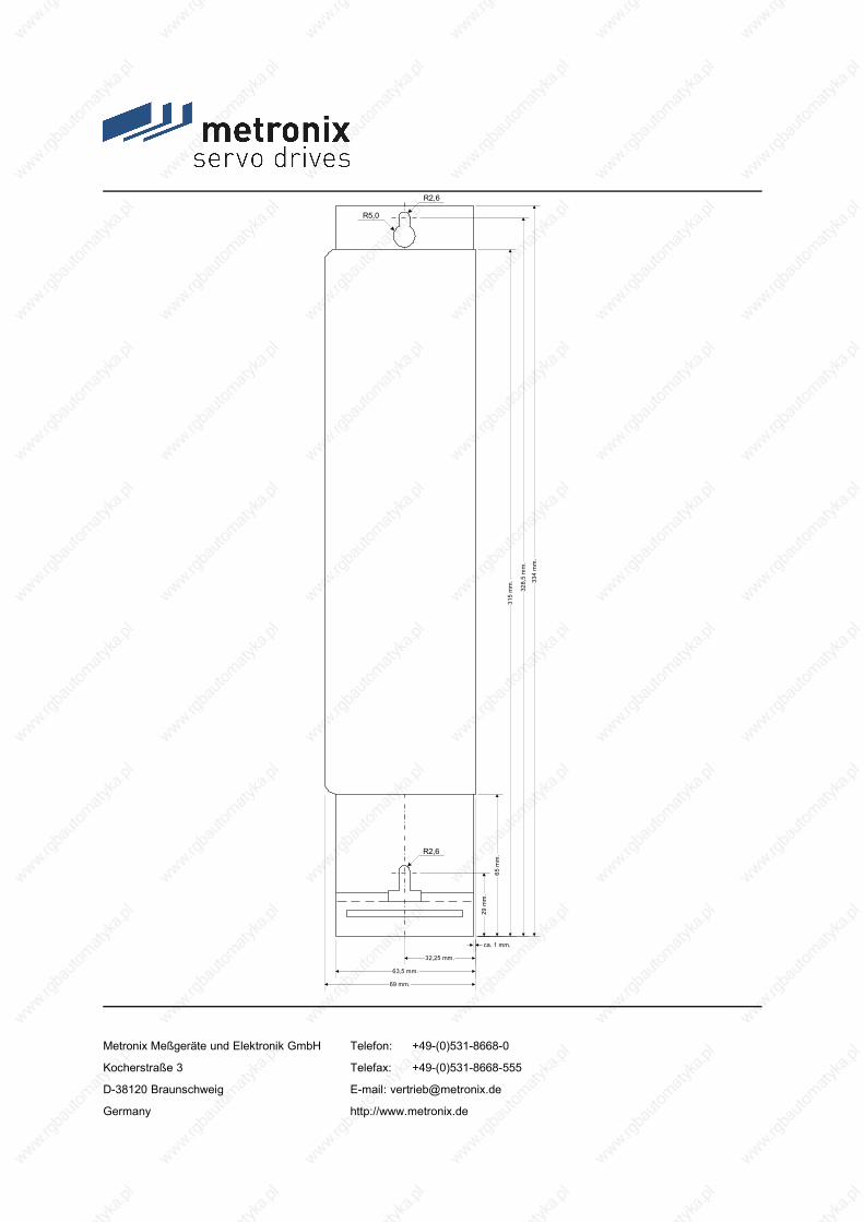
R2,6
R5,0
334
mm
.
65 m
m.
315
mm
.
29 m
m.
328,
5 m
m.
32,25 mm.
63,5 mm.
69 mm.
ca. 1 mm.
R2,6
Metronix Meßgeräte und Elektronik GmbH Telefon: +49-(0)531-8668-0
Kocherstraße 3 Telefax: +49-(0)531-8668-555
D-38120 Braunschweig E-mail: [email protected]
Germany http://www.metronix.de

Figure 15: Servo positioning controller ARS 2300: Mounting plate
Metronix Meßgeräte und Elektronik GmbH Telefon: +49-(0)531-8668-0
Kocherstraße 3 Telefax: +49-(0)531-8668-555
D-38120 Braunschweig E-mail: [email protected]
Germany http://www.metronix.de

8 Electrical installation
8.1 Connector configuration
The ARS 2300 servo positioning controller is connected to the supply voltage, the motor, the external braking resistor and the holding brake as shown in Figure 16.
Metronix Meßgeräte und Elektronik GmbH Telefon: +49-(0)531-8668-0
Kocherstraße 3 Telefax: +49-(0)531-8668-555
D-38120 Braunschweig E-mail: [email protected]
Germany http://www.metronix.de
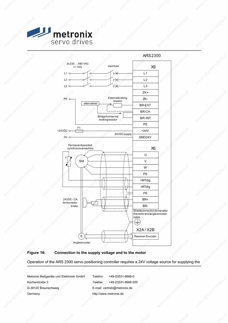
PE
+24V
GND24V
Resolver / EncoderE
X2A / X2B
ARS 2300
24VDC supply
Angle encoder
Shield connection terminal forthe motor and angle encodercable
PE
+24VDC
0V
F1
ZK+
ZK-
BR-CH
BR-INT
L1
L2
X93x 230 ... 480 VAC
+/- 10%
L1
L2
L3L3
BR-EXT
U
V
W
PE
+MTdig
-MTdig
PE
BR+
BR-
SM
24VDC / 2Afor the motor
brake
X6
T
Permanently excitedsynchronous machine
main fuse
External brakingresistor
Bridge for internalbraking resistor
alternative!
Figure 16: Connection to the supply voltage and to the motor
Operation of the ARS 2300 servo positioning controller requires a 24V voltage source for supplying the
Metronix Meßgeräte und Elektronik GmbH Telefon: +49-(0)531-8668-0
Kocherstraße 3 Telefax: +49-(0)531-8668-555
D-38120 Braunschweig E-mail: [email protected]
Germany http://www.metronix.de

electronic system. This voltage source has to be connected to terminals +24V and GND24V.
The power output stage is connected either to terminals L1, L2 and L3 for AC supply or to terminals ZK+ and ZK- for DC supply.
The motor is connected to terminals U, V, W. The motor temperature switch (PTC or normally closed contact) is connected to terminals +Mtdig and -Mtdig, if the switch is integrated in one cable together with the motor phases. If an analog temperature sensor (e.g. KTY81) is used in the motor, it is connected to [X2A] or [X2B] through the encoder cable.
The connection of the rotary encoder to [X2A] / [X2B] via the D-Sub connector is roughly shown in Figure 16.
The ARS 2300 servo positioning controller must be connected to ground with its PE connector.
The ARS 2300 servo positioning controller must be completely wired before the operating voltages for the DC-link and the electronic system can be switched on. In the case of inverted wiring of the operating voltage connections, an excessive operating voltage or a mix-up of operating voltage and motor connections, the ARS 2300 servo positioning controller will be damaged.
8.2 Complete ARS 2300 system
The complete ARS 2300 servo positioning controller system is shown in Figure 17. The following components are required for using the servo positioning controller:
Mains main switch
Fault-current circuit breaker (RCD), AC/DC sensitive 300mA (if required by an application)
Automatic circuit breaker
ARS 2300 servo positioning controller
Motor with motor cable
Mains cable
A PC with a serial connecting cable is required for parameterisation.
A slow-blow (B16) three-phase automatic circuit breaker of 16 A has to be installed in the mains supply line.
Metronix Meßgeräte und Elektronik GmbH Telefon: +49-(0)531-8668-0
Kocherstraße 3 Telefax: +49-(0)531-8668-555
D-38120 Braunschweig E-mail: [email protected]
Germany http://www.metronix.de

In the case of demanded UL-certifying the following data for the main fuse are to be considered:Listed Circuit Breaker according UL 489, rated 480Y/277 Vac, 16 A, SCR 10 kA
Metronix Meßgeräte und Elektronik GmbH Telefon: +49-(0)531-8668-0
Kocherstraße 3 Telefax: +49-(0)531-8668-555
D-38120 Braunschweig E-mail: [email protected]
Germany http://www.metronix.de

PC with ServoCommanderparameterisation program
Motor with angleencoder
24V DC voltage supply
Automatic circuitbreaker
Main switch 400 V AC mains connection
AR
S 23
10
metronix
COOPER ToolsExternal brakingresistor (if required)
Figure 17: Complete set-up of ARS 2300 with motor and PC
Metronix Meßgeräte und Elektronik GmbH Telefon: +49-(0)531-8668-0
Kocherstraße 3 Telefax: +49-(0)531-8668-555
D-38120 Braunschweig E-mail: [email protected]
Germany http://www.metronix.de

8.3 Connection: Power supply [X9]
The ARS 2300 servo positioning controller receives its 24VDC power supply for the electronic control system through connector [X9].
Mains voltage supply is three-phase. As an alternative to AC power supply or as a DC-link, direct DC power supply for the DC-link is possible.
8.3.1 Configuration on the device [X9]
PHOENIX Power-Combicon PC 4/11-G-7.62
8.3.2 Mating connector [X9]
PHOENIX Power-Combicon PC 4 HV/11-ST-7.62
8.3.3 Pin assignment [X9]
Table 23: Pin assignment [X9]
Pin no.
Name Value Specification
1 L1 230...480VAC ±10% Mains phase 1
Metronix Meßgeräte und Elektronik GmbH Telefon: +49-(0)531-8668-0
Kocherstraße 3 Telefax: +49-(0)531-8668-555
D-38120 Braunschweig E-mail: [email protected]
Germany http://www.metronix.de

50...60Hz2 L2 Mains phase 2
3 L3 Mains phase 3
4 ZK+ < 700VDC Alternative supply: Positive DC-link voltage
5 ZK- < 700VDC Alternative supply: Negative DC-link voltage
6 BR-EXT < 800VDC Connection of the external braking resistor
7 BR-CH < 800VDC Brake chopper connection for
internal braking resistor against BR-INT
external braking resistor against BR-EXT
8 BR-INT < 800VDC Connection of the internal braking resistor (bridge to BR-CH if the internal resistor is used)
9 PE PE Connection of mains ground conductor
10 +24V +24VDC / 3A Supply for control section (1A) and holding brake (2A)
11 GND24V GND24VDC Supply reference potential
8.3.4 Cable type and configuration [X9]
The cable names given refer to cables made by Lapp. They have proven to be reliable and are successfully used in many applications. However, it is also possible to use comparable cables from other manufacturers, e.g. Lütze or Helukabel.
For 400 VAC supply:
LAPP KABEL ÖLFLEX-CLASSIC 110; 4 x 1.5 mm²
8.3.5 Connection notes [X9]
Metronix Meßgeräte und Elektronik GmbH Telefon: +49-(0)531-8668-0
Kocherstraße 3 Telefax: +49-(0)531-8668-555
D-38120 Braunschweig E-mail: [email protected]
Germany http://www.metronix.de

PHOENIX Power-Combicon at X9
1
4
7
9
2
5
8
3
Power supply connection
6
BR-CH
L1
L2
L3
PE
BR-INT
ZK-
BR-EXT
ZK+
GND24V
+24V
11
10
External brakingresistor
Alternative !
Figure 18: Power supply [X9]
The ARS 2300 servo positioning controller has an internal brake chopper with braking resistor. For more braking power, an external braking resistor can be connected to pin-and-socket connector [X9].
Table 24: Pin-and-socket connector [X9]: External braking resistor
Pin no.
Name Value Specification
6 BR-EXT < 800VDC Connection of the external braking resistor
7 BR-CH < 800VDC Brake chopper connection for the internal braking resistor against BR-INT and for the external braking resistor against BR-EXT
8 BR-INT < 800VDC Connection of the internal braking resistor (bridge to BR-CH if the internal resistor is used)
If no external braking resistor is used, a bridge must be connected between PIN7 and PIN8 in order to activate the DC-link precharge and the DC-link rapid discharge!
Metronix Meßgeräte und Elektronik GmbH Telefon: +49-(0)531-8668-0
Kocherstraße 3 Telefax: +49-(0)531-8668-555
D-38120 Braunschweig E-mail: [email protected]
Germany http://www.metronix.de

8.4 Connection: Motor [X6]
8.4.1 Configuration on the device [X6]
PHOENIX Power-Combicon PC 4/9-G-7.62
8.4.2 Mating connector [X6]
PHOENIX Power-Combicon PC 4 HV/9-ST-7.62
8.4.3 Pin assignment [X6]
Table 25: Pin assignment [X6]
Pin no.
Name Value Specification
1 BR- 0V brake Holding brake (motor), signal level depending on switching state, high-side / low-side switch2 BR+ 24V brake
3 PE PE Cable shield for the holding brake and the temperature sensor
4 -MTdig GND Motor temperature sensor, normally closed contact, normally open contact, PTC, KTY…5 +Mtdig +3.3V / 5mA
6 PE PE Protective ground conductor of the motor
7 W 0...360Veff
0...2.5 Aeff (ARS 2302)
0...5 Aeff (ARS 2305)
0...10 Aeff (ARS 2310)
0...1000Hz
Connection of the three motor phases
8 V
9 U
Metronix Meßgeräte und Elektronik GmbH Telefon: +49-(0)531-8668-0
Kocherstraße 3 Telefax: +49-(0)531-8668-555
D-38120 Braunschweig E-mail: [email protected]
Germany http://www.metronix.de

The outer cable shield of the motor cable has to be connected flat to the mounting plate of the controller housing using shield terminal SK14.
8.4.4 Type and configuration of cable [X6] at the ARS 2302 and ARS 2305
The cable names given refer to cables made by Lapp. They have proven to be reliable and are successfully used in many applications. However, it is also possible to use comparable cables from other manufacturers, e.g. Lütze or Helukabel.
LAPP KABEL ÖLFLEX-SERVO 700 CY; 4 G 1.5 + 2 x (2 x 0.75) StD-CY; ∅ 12.7 mm,with tinned CU shielding
For highly flexible applications:
LAPP KABEL ÖLFLEX-SERVO 755 CP; 4 G 1.5 + 2 x (2 x 0.75 StD) CP; ∅ 15.8 mm,with tinned CU shieldingfor highly flexible use in drag chains
8.4.5 Type and configuration of cable [X6] at the ARS 2310
The cable names given refer to cables made by Lapp. They have proven to be reliable and are successfully used in many applications. However, it is also possible to use comparable cables from other manufacturers, e.g. Lütze or Helukabel.
LAPP KABEL ÖLFLEX-SERVO 700 CY; 4 G 2.5 + (2 x 2 x 0.75) StD-CY; ∅ 14.9 mm,with tinned CU shielding
For highly flexible applications:
LAPP KABEL ÖLFLEX-SERVO 755 CP; 4 G 2.5 + 2 x (2 x 0.75 StD) CP; ∅ 16.0 mm,with tinned CU shielding
Metronix Meßgeräte und Elektronik GmbH Telefon: +49-(0)531-8668-0
Kocherstraße 3 Telefax: +49-(0)531-8668-555
D-38120 Braunschweig E-mail: [email protected]
Germany http://www.metronix.de

for highly flexible use in drag chains
8.4.6 Connection notes [X6]
PHOENIX Power-Combicon at X6
PE (optional)
Motor phase U or 1
Motor phase V or 2
Motor phase W or 3
BR-
BR+
+MTdig
-MTdig
Motor connector
PE (motor)
Shield terminal SK14
1
4
7
9
2
5
8
3
6
Connector housing
Motor housing
Figure 19: Motor connection [X6]
Connect the inner shields to PIN 3. Maximum length: 40 mm.
Maximum length of unshielded cores: 35 mm.
Metronix Meßgeräte und Elektronik GmbH Telefon: +49-(0)531-8668-0
Kocherstraße 3 Telefax: +49-(0)531-8668-555
D-38120 Braunschweig E-mail: [email protected]
Germany http://www.metronix.de

Connect the shield on the controller side flat to shield terminal SK14.
Connect the shield on the motor side flat to the connector or motor housing. Maximum length: 40 mm.
Terminals ZK+ and ZK- can be used to interconnect the DC-links of several ARS 2300 servo positioning controllers. DC-link coupling is interesting for applications with high braking energies or for applications requiring movements to be carried out even in the case of power failure. Further information can be found in Application Note 67.
Terminals BR+ and BR- can be used to connect a holding brake of the motor. The locking brake is supplied with power through the power supply of the servo positioning controller. Please note the maximum output current provided by the ARS 2300 servo positioning controller. A relay may have to be installed between the device and the locking brake as shown in Figure 20.
Br+
Br-
ARS 2300
Motor
+ 24 V power supply unit
GND power supply unit
+24 V brake
GND brake Freewheeling diode
Resistor and capacitor for spark suppression
capacitor for spark suppression
Figure 20: Connecting a locking brake with high current demand (> 2A) to the device
Metronix Meßgeräte und Elektronik GmbH Telefon: +49-(0)531-8668-0
Kocherstraße 3 Telefax: +49-(0)531-8668-555
D-38120 Braunschweig E-mail: [email protected]
Germany http://www.metronix.de

Switching of inductive direct current via relays produces strong current and sparking. For interference suppression, we recommend integrated RC suppressor elements, e.g. made by Evox RIFA, type: PMR205AC6470M022 (RC element with 22Ω in series with 0.47uF).
8.5 Connection: I/O communication [X1]
The following Figure 21 shows the basic function of the digital and analog inputs and outputs. The ARS 2300 servo positioning controller is shown on the right-hand side, the control connection on the left-hand side. The cable configuration is also shown.
The ARS 2300 servo positioning controller has two potential ranges:
Analog inputs and outputs:
All analog inputs and outputs refer to AGND. AGND is internally connected to GND, the reference potential for the control section with µC and AD converters in the servo positioning controller. This potential range is electrically isolated from the 24V range and from the DC-link.
24V inputs and outputs:
These signals refer to the 24V supply voltage of the ARS 2300 servo positioning controller which is supplied via [X9]. They are separated from the reference potential of the control section by means of optocouplers.
Metronix Meßgeräte und Elektronik GmbH Telefon: +49-(0)531-8668-0
Kocherstraße 3 Telefax: +49-(0)531-8668-555
D-38120 Braunschweig E-mail: [email protected]
Germany http://www.metronix.de

24
11
19
6
18
14
1
5
14
17
4
163
152
13DOUT3
DIN9
DOUT0
DIN0
GND24
+24VDC
+VREF
AMON0
AIN1
AIN0
Pin no.X1
AMON1
AIN2
#AIN0
AGND
AGND
DOUTx
GND24
+24VDC
+24VDC
GND
GND24
PEPE
100 mAmax !
100 mAmax !
Connector housing
+VREF
AIN0
#AIN0
AGND
AIN1 / AIN2
AGND
+15V
AGND
AGND
AMONx
AGND
GND AGND
DINx
GND24GND
Control System ARS 2300
Metronix Meßgeräte und Elektronik GmbH Telefon: +49-(0)531-8668-0
Kocherstraße 3 Telefax: +49-(0)531-8668-555
D-38120 Braunschweig E-mail: [email protected]
Germany http://www.metronix.de

Figure 21: Basic circuit diagram of connection [X1]
The ARS 2300 servo positioning controller has one differential analog input (AIN0) and two single-ended analog inputs designed for input voltages in the range of ± 10V. Inputs AIN0 and #AIN0 are led to the control system via twisted cables (twisted-pair type). If the control system has single-ended outputs, the output is connected to AIN0 and #AIN0 is connected to the reference potential of the control system. If the control system has differential outputs, they have to be connected 1:1 to the differential inputs of the ARS 2300 servo positioning controller.
The reference potential AGND is connected to the reference potential of the control system. This is necessary in order to prevent the differential input of the ARS 2300 servo positioning controller from being overridden by high "common-mode interferences".
There are two analog monitor outputs with output voltages in the range of ± 10V and one output for a reference voltage of +10V. These outputs can be led to the superimposed control system, the reference AGND must be carried along. If the control system has differential inputs, the "+" input of the control system is connected to the output of the ARS 2300 servo positioning controller and the "-" input of the control system to AGND.
8.5.1 Configuration on the device [X1]
D-SUB connector, 25-pin type, female
8.5.2 Mating connector [X1]
D-SUB connector, 25-pin type, male
Housing for 25-pin D-SUB connector with bolting screws of type 4/40 UNC
Metronix Meßgeräte und Elektronik GmbH Telefon: +49-(0)531-8668-0
Kocherstraße 3 Telefax: +49-(0)531-8668-555
D-38120 Braunschweig E-mail: [email protected]
Germany http://www.metronix.de

8.5.3 Pin assignment [X1]
Table 26: Pin assignment: I/O communication [X1]
Pin no. Name Value Specification
1 AGND - Shield for analog signals
14 AGND - Reference potential for analog signals
2 AIN0 UEin = ±10V RI ≥30kΩ
Setpoint input 0, differential, 30V input voltage max.
15 #AIN0
3 AIN1 UEin = ±10VRI ≥30kΩ
Setpoint inputs 1 and 2, single-ended, 30V input voltage max.
16 AIN2
4 +VREF +10V Reference output for setpoint potentiometer
17 AMON0 ±10V Analog monitor output 0
5 AMON1 ±10V Analog monitor output 1
18 +24V 24VDC / 100mA 24VDC supply, led out
6 GND24 - Reference potential for digital inputs/outputs
19 DIN0 POS Bit0 Positioning target selection bit0
7 DIN1 POS Bit1 Positioning target selection bit1
20 DIN2 POS Bit2 Positioning target selection bit2
8 DIN3 POS Bit3 Positioning target selection bit3
21 DIN4 FG_E Output stage enabling
9 DIN5 FG_R Input for controller enabling
22 DIN6 END0 Input of limit switch 0 (blocks n < 0)
10 DIN7 END1 Input of limit switch 1 (blocks n > 0)
23 DIN8 START Input for start of positioning process
11 DIN9 SAMP High-speed input
Metronix Meßgeräte und Elektronik GmbH Telefon: +49-(0)531-8668-0
Kocherstraße 3 Telefax: +49-(0)531-8668-555
D-38120 Braunschweig E-mail: [email protected]
Germany http://www.metronix.de

Pin no. Name Value Specification
24 DOUT0 / BEREIT 24VDC / 100mA Output for readiness for operation
12 DOUT1 24VDC / 100mA Freely programmable output
25 DOUT2 24VDC / 100mA Freely programmable output
13 DOUT3 24VDC / 100mA Freely programmable output
8.5.4 Cable type and configuration [X1]
The cable names given refer to cables made by Lapp. They have proven to be reliable and are successfully used in many applications. However, it is also possible to use comparable cables from other manufacturers, e.g. Lütze or Helukabel.
LAPP KABEL UNITRONIC-LiYCY; 25 x 0.25 mm²
Figure 21 shows the cable between the ARS 2300 servo positioning controller and the control system. The cable shown has two cable shields.
The outer cable shield is connected to PE on both sides. Inside the ARS 2300 servo positioning controller, the connector housing of the D-Sub connector is connected to PE. If metal D-Sub connector housings are used, the cable shield is simply squeezed underneath the strain relief.
Often an unshielded cable is sufficient for 24V signals. In environments with high interferences or in the case of long cables (l > 2m) between the control system and the ARS 2300 servo positioning controller, Metronix recommends using shielded control cables.
Although the analog inputs of the ARS 2300 servo positioning controller are differential, using unshielded cables for the analog signals is not recommended as interferences, e.g. caused by switching contacts, or output stage interferences of the converters can reach high amplitudes. They couple themselves into the analog signals and cause common-mode interferences which may lead to deviations of the analog measured values.
Metronix Meßgeräte und Elektronik GmbH Telefon: +49-(0)531-8668-0
Kocherstraße 3 Telefax: +49-(0)531-8668-555
D-38120 Braunschweig E-mail: [email protected]
Germany http://www.metronix.de

In the case of limited cable lengths (l < 2m, wiring inside the control cabinet), the outer dual-sided PE shield is enough to guarantee trouble-free operation.
For optimal interference suppression of the analog signals, the cores for the analog signals have to be shielded together and separated from other cores. At the ARS 2300 servo positioning controller, the inner cable shield is connected on one side to AGND (pin 1 or 14). It can be connected on both sides in order to establish a connection between the reference potentials of the control system and the ARS 2300 servo positioning controller. Pins 1 and 14 are directly connected to each other inside the controller.
8.5.5 Connection notes [X1]
The digital inputs are rated for control voltages of 24V. The high signal level already ensures a high level of interference immunity of these inputs. The ARS 2300 servo positioning controller provides an auxiliary voltage of 24V which may be loaded with 100 mA maximum. As a result, the inputs can be activated directly via switches. Activation via the 24V outputs of a PLC is of course also possible.
The digital outputs are so-called "high-side switches". This means that the 24V of the ARS 2300 servo positioning controller are actively switched through to the output. Loads such as lamps, relays, etc. are thus switched from the output to GND24. The four outputs DOUT0 to DOUT3 can be loaded with a maximum of 100mA each. The outputs can also be led directly to 24V inputs of a PLC.
8.6 Connection: Safe Standstill [X3]
The description of the safety function "Safe Torque-Off" is in chapter 6 Functional safety technology.
8.6.1 Configuration on the device [X3]
PHOENIX Mini-Combicon MC 1.5/ 6-GF-3.81
8.6.2 Mating connector [X3]
PHOENIX Mini-Combicon MC 1.5/6-STF-3.81
Metronix Meßgeräte und Elektronik GmbH Telefon: +49-(0)531-8668-0
Kocherstraße 3 Telefax: +49-(0)531-8668-555
D-38120 Braunschweig E-mail: [email protected]
Germany http://www.metronix.de

8.6.3 Pin assignment [X3]
Table 27: Pin assignment [X3]
Pin no.
Name Value Specification
1 24V 24VDC 24VDC supply, led out
(Without safety measures in accordance with Performance level d: Bridge pin 1 and 2)
2 REL 0V / 24VDC Setting and resetting of the relay for interrupting the driver supply of the output stage
3 0V 0V Reference potential for PLC
4 ERR 0V / 24VDC Signalling contact "Error on safety module"
5 NC1 250VAC max.switching voltage
Floating response contact of driver supply;normally closed contact
6 NC2
8.6.4 Connection notes [X3]
Metronix Meßgeräte und Elektronik GmbH Telefon: +49-(0)531-8668-0
Kocherstraße 3 Telefax: +49-(0)531-8668-555
D-38120 Braunschweig E-mail: [email protected]
Germany http://www.metronix.de

1
4
2
5
3
6
PHOENIX MINI COMBIONat [X3]
Without the safety function "safe stop":bridge pins 1 and 2
Figure 22: Connection notes [X3]: without safety function
8.7 Connection: Resolver [X2A]
8.7.1 Configuration on the device [X2A]
1 D-SUB connector, 9-pin type, female
8.7.2 Mating connector [X2A]
D-SUB connector, 9-pin type, male
Housing for 9-pin D-SUB connector with bolting screws of type 4/40 UNC
Metronix Meßgeräte und Elektronik GmbH Telefon: +49-(0)531-8668-0
Kocherstraße 3 Telefax: +49-(0)531-8668-555
D-38120 Braunschweig E-mail: [email protected]
Germany http://www.metronix.de

8.7.3 Pin assignment [X2A]
Table 28: Pin assignment [X2A]
Pin no. Name Value Specification
1 S2 3.5Veff /5-10kHz
Ri > 5kΩ
SINE trace signal, differential
6 S4
2 S1 3.5Veff /5-10kHz
Ri > 5kΩ
COSINE trace signal, differential
7 S3
3 AGND 0V Shield for signal pairs (inner shield)
8 MT- GND Temperature sensor reference potential
4 R1 7Veff /5-10kHz IA ≤ 150mAeff
Carrier signal for resolver
9 R2 GND
5 MT+ +3.3V / Ri=2kΩ Motor temperature sensor, normally closed contact, PTC, KTY…
The outer cable shield of the angle encoder cable has to be connected flat to the mounting plate of the controller housing using shield terminal SK14.
8.7.4 Cable type and configuration [X2A]
Metronix Meßgeräte und Elektronik GmbH Telefon: +49-(0)531-8668-0
Kocherstraße 3 Telefax: +49-(0)531-8668-555
D-38120 Braunschweig E-mail: [email protected]
Germany http://www.metronix.de

The cable names given refer to cables made by Lapp. They have proven to be reliable and are successfully used in many applications. However, it is also possible to use comparable cables from other manufacturers, e.g. Lütze or Helukabel.
LAPP KABEL ÖLFLEX-SERVO 720 CY; 3 x (2 x 0.14 CY) + 2 x (0.5 CY) CY; ∅ 8.5 mm,with tinned CU shieldingError during angle detection up to about 1.5° at a cable length of 50 m
Use 2 x (0.5 CY) for the resolver carrier!
For highly flexible applications:
LAPP KABEL ÖLFLEX-SERVO-FD 770 CP; 3 x (2 x 0.14 D12Y) + 2 x (0.5 D12Y) CP; ∅ 8.3 mm,with tinned CU shieldingError during angle detection up to about 1.5° at a cable length of 50 m
Use 2 x (0.5 D12Y) for the resolver carrier!
8.7.5 Connection notes [X2A]
connectorhousing
1
59
6
shield (optional)
S3 / COS-
S1 / COS+
S2 / SIN+
AGND TEMP
R1 / carrier+
R1 / carrier-
TEMP+
S4 / SIN-
Resolver output of themotor
D-SUBconnectorat X2A
maleconnector
connector housing
2
3
4
5
6
7
8
1
9
Figure 23: Pin assignment: Resolver connection [X2A]
Metronix Meßgeräte und Elektronik GmbH Telefon: +49-(0)531-8668-0
Kocherstraße 3 Telefax: +49-(0)531-8668-555
D-38120 Braunschweig E-mail: [email protected]
Germany http://www.metronix.de

The outer shield is always connected to PE (connector housing) on the controller side.
The three inner shields are connected on one side to PIN3 of [X2A] of the ARS 2300 servo positioning controller.
8.8 Connection: Encoder [X2B]
8.8.1 Configuration on the device [X2B]
D-SUB connector, 15-pin type, female
8.8.2 Mating connector [X2B]
D-SUB connector, 15-pin type, male
Housing for 15-pin D-SUB connector with bolting screws of type 4/40 UNC
8.8.3 Pin assignment [X2B]
Table 29: Pin assignment: Analog incremental encoder - option [X2B]
Pin no. Name Value Specification
1 MT+ +3.3V / Ri=2kΩ Motor temperature sensor, normally closed contact, PTC, KTY…
9 U_SENS+ 5V...12V Sensor lines for encoder supply
Metronix Meßgeräte und Elektronik GmbH Telefon: +49-(0)531-8668-0
Kocherstraße 3 Telefax: +49-(0)531-8668-555
D-38120 Braunschweig E-mail: [email protected]
Germany http://www.metronix.de

Pin no. Name Value Specification
RI ≈ 1kΩ2 U_SENS-
10 US 5V / 12V/ ±10%Imax = 300mA
Operating voltage for high-resolution incremental encoders
3 GND 0V Reference potential for encoder supply and motor temperature sensor
11 R 0.2VSS.. 0.8VSS
RI ≈ 120ΩReset pulse trace signal (differential) of high-resolution incremental encoder
4 #R
12 COS_Z1 *) 1VSS±10%RI ≈ 120Ω
COSINE commutation signal (differential) of high-resolution incremental encoder
5 #COS_Z1 *)
13 SIN_Z1 *) 1VSS±10%RI ≈ 120Ω
SINE commutation signal (differential) of high-resolution incremental encoder
6 #SIN_Z1 *)
14 COS_Z0 *) 1VSS±10%RI ≈ 120Ω
COSINE trace signal (differential) of high-resolution incremental encoder
7 #COS_Z0 *)
15 SIN_Z0 *) 1VSS±10%RI ≈ 120Ω
SINE trace signal (differential) of high-resolution incremental encoder
8 #SIN_Z0 *)
*) Heidenhain encoder: A=SIN_Z0; B=COS_Z0; C=SIN_Z1; D=COS_Z1
Metronix Meßgeräte und Elektronik GmbH Telefon: +49-(0)531-8668-0
Kocherstraße 3 Telefax: +49-(0)531-8668-555
D-38120 Braunschweig E-mail: [email protected]
Germany http://www.metronix.de

Table 30: Pin assignment: Incremental encoder with serial interface (e.g. EnDat, HIPERFACE) - option [X2B]
Pin no. Name Value Specification
1 MT+ +3.3V / Ri=2kΩ Motor temperature sensor, normally closed contact, PTC, KTY…
9 U_SENS+ 5V...12V / RI ≈ 1kΩ
Sensor lines for encoder supply
2 U_SENS-
10 US 5V / 12V/ ±10%Imax = 300mA
Operating voltage for high-resolution incremental encoders
3 GND 0V Reference potential for encoder supply and motor temperature sensor
11
4
12 DATA 5VSS
RI ≈ 120ΩBi-directional RS485 data line (differential) (EnDat/HIPERFACE)
5 #DATA
13 SCLK 5VSS
RI ≈ 120ΩClock output RS485 (differential)
(EnDat)6 #SCLK
14 COS_Z0 *) 1VSS±10%RI ≈ 120Ω
COSINE trace signal (differential) of high-resolution incremental encoder
7 #COS_Z0 *)
15 SIN_Z0 *) 1VSS±10%RI ≈ 120Ω
SINE trace signal (differential) of high-resolution incremental encoder
8 #SIN_Z0 *)
*) Heidenhain encoder: A=SIN_Z0; B=COS_Z0
Metronix Meßgeräte und Elektronik GmbH Telefon: +49-(0)531-8668-0
Kocherstraße 3 Telefax: +49-(0)531-8668-555
D-38120 Braunschweig E-mail: [email protected]
Germany http://www.metronix.de
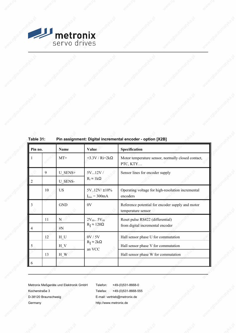
Table 31: Pin assignment: Digital incremental encoder - option [X2B]
Pin no. Name Value Specification
1 MT+ +3.3V / Ri=2kΩ Motor temperature sensor, normally closed contact, PTC, KTY…
9 U_SENS+ 5V...12V / RI ≈ 1kΩ
Sensor lines for encoder supply
2 U_SENS-
10 US 5V..12V/ ±10%Imax = 300mA
Operating voltage for high-resolution incremental encoders
3 GND 0V Reference potential for encoder supply and motor temperature sensor
11 N 2VSS.. 5VSS
RI ≈ 120ΩReset pulse RS422 (differential) from digital incremental encoder
4 #N
12 H_U 0V / 5VRI ≈ 2kΩ
an VCC
Hall sensor phase U for commutation
5 H_V Hall sensor phase V for commutation
13 H_W Hall sensor phase W for commutation
6
Metronix Meßgeräte und Elektronik GmbH Telefon: +49-(0)531-8668-0
Kocherstraße 3 Telefax: +49-(0)531-8668-555
D-38120 Braunschweig E-mail: [email protected]
Germany http://www.metronix.de

Pin no. Name Value Specification
14 A 2VSS.. 5VSS
RI ≈ 120ΩA trace signal RS422 (differential) from digital incremental encoder
7 #A
15 B 2VSS.. 5VSS
RI ≈ 120ΩB trace signal RS422 (differential) from digital incremental encoder
8 #B
The outer cable shield of the angle encoder cable has to be connected flat to the mounting plate of the controller housing using shield terminal SK14.
8.8.4 Cable type and configuration [X2B]
We recommend using the encoder connection cables authorised by the manufacturers (Heidenhain, Stegmann, etc.) for their various products. If the manufacturer does not recommend a particular cable, we recommend setting up the encoder connection cables as described below.
For the angle encoder supply US and GND, we recommend a minimum cross-section of 0.25 mm² for an angle encoder cable length up to 25 m, and a minimum cross-section of 0.5 mm² for an angle encoder cable length up to 50 m.
8.8.5 Connection notes [X2B]
Metronix Meßgeräte und Elektronik GmbH Telefon: +49-(0)531-8668-0
Kocherstraße 3 Telefax: +49-(0)531-8668-555
D-38120 Braunschweig E-mail: [email protected]
Germany http://www.metronix.de

2
3
4
5
9
10
11
1
12
shield (optional)
connector housing
6
7
8
13
14
15
connectorhousing
19
8 15
maleconnector
COS_Z0
#COS_Z0
#SIN_Z1
#SIN_Z0
SIN_Z1
#COS_Z1
COS_Z1
#R
SIN_Z0
R
GND
US
Output of the analog incrementalencoder at the motor
D-SUB connectorat X2B
U_SENS-
U_SENS+
TEMP+
TEMP-
Figure 24: Pin assignment: Analog incremental encoder - option [X2B]
Metronix Meßgeräte und Elektronik GmbH Telefon: +49-(0)531-8668-0
Kocherstraße 3 Telefax: +49-(0)531-8668-555
D-38120 Braunschweig E-mail: [email protected]
Germany http://www.metronix.de

2
3
4
5
9
10
11
1
12
Shield (optional)
Output of the incremental encoder with serial interface at the motor
D-SUB connector at X2B
Connector housing
6
7
8
13
14
15
Connector housing
1 9
8 15 Male connector COS_Z0
#COS_Z0
#SCLK
#SIN_Z0
SCLK #DATA DATA
SIN_Z0
GND US
U_SENS- U_SENS+
TEMP+ TEMP-
Figure 25: Pin assignment: Incremental encoder with serial interface (e.g. EnDat, HIPERFACE) - option [X2B]
Metronix Meßgeräte und Elektronik GmbH Telefon: +49-(0)531-8668-0
Kocherstraße 3 Telefax: +49-(0)531-8668-555
D-38120 Braunschweig E-mail: [email protected]
Germany http://www.metronix.de

2
3
4
5
9
10
11
1
12
shield (optional)
Output of the digital incrementalencoder at the motor
D-SUB connectorat X2B
connector housing
6
7
8
13
14
15
connectorhousing
19
8 15
maleconnector
B#
B
GND
A
VCC
N
N#
SENSE-
A#
SENSE+
HALL_U
HALL_V
HALL_W
TEMP+
TEMP-
Figure 26: Pin assignment: Digital incremental encoder - option [X2B]
8.9 Connection: Incremental encoder input [X10]
8.9.1 Configuration on the device [X10]
D-SUB connector, 9-pin type, female
8.9.2 Mating connector [X10]
D-SUB connector, 9-pin type, male
Metronix Meßgeräte und Elektronik GmbH Telefon: +49-(0)531-8668-0
Kocherstraße 3 Telefax: +49-(0)531-8668-555
D-38120 Braunschweig E-mail: [email protected]
Germany http://www.metronix.de

Housing for 9-pin D-SUB connector with bolting screws of type 4/40 UNC
8.9.3 Pin assignment [X10]
Table 32: Pin assignment [X10]: Incremental encoder input
Pin no. Name Value Specification
1 A / CLK 5V / RI ≈ 120Ω Incremental encoder signal A / Stepper motor signal CLK Positive polarity in accordance with RS422
6 A# / CLK# 5V / RI ≈ 120Ω Incremental encoder signal A / Stepper motor signal CLK Negative polarity in accordance with RS422
2 B / DIR 5V / RI ≈ 120Ω Incremental encoder signal B / Stepper motor signal DIR Positive polarity in accordance with RS422
7 B# / DIR# 5V / RI ≈ 120Ω Incremental encoder signal B / Stepper motor signal DIR Negative polarity in accordance with RS422
3 N 5V / RI ≈ 120Ω Incremental encoder reset pulse NPositive polarity in accordance with RS422
8 N# 5V / RI ≈ 120Ω Incremental encoder reset pulse NNegative polarity in accordance with RS422
4 GND - Reference GND for the encoder
9 GND - Shield for the connecting cable
Metronix Meßgeräte und Elektronik GmbH Telefon: +49-(0)531-8668-0
Kocherstraße 3 Telefax: +49-(0)531-8668-555
D-38120 Braunschweig E-mail: [email protected]
Germany http://www.metronix.de

5 VCC +5V±5% 100mA Auxiliary supply, can be loaded with 100mA maximum, but short-circuit-proof!
8.9.4 Cable type and configuration [X10]
We recommend using encoder connection cables in which the incremental encoder signals are twisted in pairs and the individual pairs are shielded.
8.9.5 Connection notes [X10]
Input [X10] can be used to process incremental encoder signals and pulse direction signals like the ones generated by control cards for stepper motors.
The input amplifier at the signal input is designed to process differential signals in accordance with the RS422 interface standard. It may also be possible to process other signals and levels (e.g. 5V single-ended or 24VHTL from a PLC). Please contact your distributor.
2
3
4
5
6
7
8
1
9
connectorhousing
1
59
6
shield (optional)
B# / DIR#
B / DIR
N
A / CLK
N#
GND
VCC
A# / CLK#
Incremental encoderinput
D-SUBconnectorat X10
Stift
connector housing
Figure 27: Pin assignment [X10]: Incremental encoder input
Metronix Meßgeräte und Elektronik GmbH Telefon: +49-(0)531-8668-0
Kocherstraße 3 Telefax: +49-(0)531-8668-555
D-38120 Braunschweig E-mail: [email protected]
Germany http://www.metronix.de

8.10 Connection: Incremental encoder output [X11]
8.10.1 Configuration on the device [X11]
D-SUB connector, 9-pin type, female
8.10.2 Mating connector [X11]
D-SUB connector, 9-pin type, male
Housing for 9-pin D-SUB connector with bolting screws of type 4/40 UNC
8.10.3 Pin assignment [X11]
Table 33: Pin assignment [X11]: Incremental encoder output
Pin no. Name Value Specification
Metronix Meßgeräte und Elektronik GmbH Telefon: +49-(0)531-8668-0
Kocherstraße 3 Telefax: +49-(0)531-8668-555
D-38120 Braunschweig E-mail: [email protected]
Germany http://www.metronix.de

1 A 5V / RA ≈ 66Ω *) Incremental encoder signal A
6 A# 5V / RA ≈ 66Ω *) Incremental encoder signal A#
2 B 5V / RA ≈ 66Ω *) Incremental encoder signal B
7 B# 5V / RA ≈ 66Ω *) Incremental encoder signal B#
3 N 5V / RA ≈ 66Ω *) Incremental encoder reset pulse N
8 N# 5V / RA ≈ 66Ω *) Incremental encoder reset pulse N#
4 GND - Reference GND for the encoder
9 GND - Shield for the connecting cable
5 VCC +5V ±5% 100mA Auxiliary supply, can be loaded with 100mA maximum, but short-circuit-proof!
*) The value for RA stands for the differential output resistance.
8.10.4 Cable type and configuration [X11]
We recommend using encoder connection cables in which the incremental encoder signals are twisted in pairs and the individual pairs are shielded.
8.10.5 Connection notes [X11]
Metronix Meßgeräte und Elektronik GmbH Telefon: +49-(0)531-8668-0
Kocherstraße 3 Telefax: +49-(0)531-8668-555
D-38120 Braunschweig E-mail: [email protected]
Germany http://www.metronix.de

2
3
4
5
6
7
8
1
9
connectorhousing
1
59
6
shield (optional)
B#
B
N
A
N#
GND
VCC
A#
Output of the incrementalencoder
D-SUBconnectortat X11
maleconnector
connector housing
Figure 28: Pin assignment [X11]: Incremental encoder output
The output driver at the signal output supplies differential signals (5V) in accordance with the RS422 interface standard.
Up to 32 additional controllers can be controlled by one device.
8.11 Connection: CAN-Bus [X4]
8.11.1 Configuration on the device [X4]
D-SUB connector, 9-pin type, male
8.11.2 Mating connector [X4]
D-SUB connector, 9-pin type, female
Housing for 9-pin D-SUB connector with bolting screws of type 4/40 UNC
Metronix Meßgeräte und Elektronik GmbH Telefon: +49-(0)531-8668-0
Kocherstraße 3 Telefax: +49-(0)531-8668-555
D-38120 Braunschweig E-mail: [email protected]
Germany http://www.metronix.de

8.11.3 Pin assignment [X4]
Table 34: Pin assignment CAN bus [X4]
Pin no. Name Value Specification
1 - - Not used
6 GND 0V CAN-GND, electrically connected to GND in the controller
2 CANL *) CAN low signal line
7 CANH *) CAN high signal line
3 GND 0V See pin no. 6
8 - - Not used
4 - - Not used
9 - - Not used
5 Schirm PE Connection for cable shield
*) An external terminating resistor of 120Ω is required on both bus ends. We recommend using metal film resistors with a 5% tolerance of type 0207, e.g. made by BCC, part no.: 232215621201.
8.11.4 Cable type and configuration [X4]
The cable names given refer to cables made by Lapp. They have proven to be reliable and are successfully used in many applications. However, it is also possible to use comparable cables from other manufacturers, e.g. Lütze or Helukabel.
Technical specification of the CAN bus cable: 2 pairs of 2 twisted cores, d ≥ 0.22 mm2, shielded, loop resistance < 0.2 Ω/m, characteristic impedance 100-120 Ω.
LAPP KABEL UNITRONIC BUS CAN; 2 x 2 x 0.22; ∅ 7.6 mm,
Metronix Meßgeräte und Elektronik GmbH Telefon: +49-(0)531-8668-0
Kocherstraße 3 Telefax: +49-(0)531-8668-555
D-38120 Braunschweig E-mail: [email protected]
Germany http://www.metronix.de

with Cu shielding
For highly flexible applications:
LAPP KABEL UNITRONIC BUS-FD P CAN UL/CSA; 2 x 2 x 0.25; ∅ 8.4 mm,with Cu shielding
8.11.5 Connection notes [X4]
When cabling the controller via the CAN bus, make sure to observe the following information and notes in order to set up a stable and interference-free system. Improper cabling may cause the CAN bus to malfunction which in turn can cause the controller to shut down with an error due to safety reasons.
The CAN bus provides an easy and fail-safe way of interconnecting all components of a system. This requires, however, compliance with the following notes on cabling.
Figure 29: CAN bus cabling example
The individual nodes of the network are always connected in line so that the CAN cable is looped through from controller to controller (see Figure 29).
A terminating resistor of 120Ω/-5% has to be present on both ends of the CAN bus cable. CAN boards or PLCs often come supplied with such a terminating resistor which has to be taken into consideration accordingly.
Shielded cables with exactly two twisted pairs must be used for cabling.
Metronix Meßgeräte und Elektronik GmbH Telefon: +49-(0)531-8668-0
Kocherstraße 3 Telefax: +49-(0)531-8668-555
D-38120 Braunschweig E-mail: [email protected]
Germany http://www.metronix.de

Use a twisted pair to connect CAN-H and CAN-L.
The cores of the other pair are used jointly for CAN-GND.
The shield of the cable is led to the CAN shield connections for all nodes.
For suitable cables and cables recommended by Metronix please refer to chapter 8.11.4 Cabletype and configuration [X4].
We advise against the use of plug adapters for cabling the CAN bus. Should this be necessary nonetheless, make sure to use metal connector housings to connect the cable shield.
In order to keep interferences as low as possible, make sure that
motor cables are not laid parallel to signal lines.
motor cables comply with Metronix specifications.
motor cables are properly shielded and grounded.
For further information on interference-free CAN bus cabling, please refer to the Controller Area Network protocol specification, version 2.0, by Robert Bosch GmbH, 1991.
8.12 Connection: RS232/COM [X5]
8.12.1 Configuration on the device [X5]
D-SUB connector, 9-pin type, male
8.12.2 Mating connector [X5]
D-SUB connector, 9-pin type, female
Housing for 9-pin D-SUB connector with bolting screws of type 4/40 UNC
Metronix Meßgeräte und Elektronik GmbH Telefon: +49-(0)531-8668-0
Kocherstraße 3 Telefax: +49-(0)531-8668-555
D-38120 Braunschweig E-mail: [email protected]
Germany http://www.metronix.de

8.12.3 Pin assignment [X5]
Table 35: Pin assignment RS232 interface [X5]
Pin no. Name Value Specification
1 - - Not used
6 - - Not used
2 RxD 10 V / RI > 2kΩ Reception line, RS232 specification
7 - - Not used
3 TxD 10 V / RA < 2kΩ Transmission line, RS232 specification
8 - - Not used
4 +RS485 - reserved for optional RS485 use
9 -RS485 - reserved for optional RS485 use
5 GND 0V Interface GND, electrically connected to GND of the digital section
8.12.4 Cable type and configuration [X5]
Interface cable for serial interface (null modem), 3 cores.
8.12.5 Connection notes [X5]
Metronix Meßgeräte und Elektronik GmbH Telefon: +49-(0)531-8668-0
Kocherstraße 3 Telefax: +49-(0)531-8668-555
D-38120 Braunschweig E-mail: [email protected]
Germany http://www.metronix.de

Servo PC
2
3
4
5
6
7
8
1
9
connectorhousing
1
59
6
connectorhousing
2
3
4
5
6
7
8
1
9
1
59
6
femaleconnector
femaleconnector
Figure 30: Pin assignment RS232 null modem cable [X5]
8.13 Notes concerning safe and EMC-compliant installation
8.13.1 Definitions and terminology
Electromagnetic compatibility (EMC) or electromagnetic interference (EMI) includes the following requirements:
Sufficient immunity of an electrical installation or an electrical device against external electrical, magnetic or electromagnetic interferences via cables or the environment.
Sufficiently small unwanted emission of electrical, magnetic or electromagnetic interference of an electrical installation or an electrical device to other devices in the vicinity via cables or through the environment.
8.13.2 General information concerning EMC
The interference emission and interference immunity of a servo drive controller always depend on the overall drive concept consisting of the following components:
Metronix Meßgeräte und Elektronik GmbH Telefon: +49-(0)531-8668-0
Kocherstraße 3 Telefax: +49-(0)531-8668-555
D-38120 Braunschweig E-mail: [email protected]
Germany http://www.metronix.de
Power supply
Servo drive controller
Motor
Electromechanical system
Configuration and type of wiring
Superimposed control system
To increase interference immunity and to decrease interference emissions, the ARS 2300 servo positioning controller comes supplied with output chokes and mains filters so that it can be used in most applications without additional external filter measures.
ARS 2300 servo positioning controllers are certified in accordance with product standard EN 61800-3 for electrical drives.
In most cases no external filter measures are required (see below).
The declaration of conformity for the EMC directive 2004/108/EC is available from the manufacturer.
Warning!
This product can cause high-frequency interference in residential areas, which could require measures for radio interference suppression.
8.13.3 EMC ranges: First and second environment
Proper installation and wiring of all connecting cables provided, the ARS 2300 servo positioning controllers fulfils the requirements of product standard EN 61800-3. This standard no longer refers to "classes", but to so-called environments. The first environment includes mains supply networks supplying residential buildings. The second environment includes mains supply networks exclusively supplying industrial buildings.
The following applies to ARS 2300 servo positioning controllers without external filter measures:
Table 36: EMC requirements: First and second environment
Metronix Meßgeräte und Elektronik GmbH Telefon: +49-(0)531-8668-0
Kocherstraße 3 Telefax: +49-(0)531-8668-555
D-38120 Braunschweig E-mail: [email protected]
Germany http://www.metronix.de

EMC type Environment Compliance with EMC requirements
Interference emission
First environment (domestic environment) Motor cable length up to 50m if C' ≤ 200 pF
Second environment (industrial environment) Motor cable length up to 50m if C' ≤ 200 pF
Interference immunity
First environment (domestic environment) Independent of motor cable length
Second environment (industrial environment)
8.13.4 EMC-compliant cabling
The following information has to be complied with for an EMC-compliant set-up of the drive system (see also chapter 8 Electrical installation, page 93):
In the first environment, the ARS 2300 servo positioning controller has to be installed in a steel control cabinet. For most applications, a standard model is sufficient to achieve sufficient suppression of interference emissions. The cable shields have to be connected to the control cabinet housing using metal lead-through terminals.
In the second environment, the ARS 2300 servo positioning controller can be used without a steel control cabinet. However, it has to be installed in a control cabinet/box (may be made of plastic) in order to ensure that it is used as intended.
The control cabinet bed plate has to be conducting (zinc-coated). The imperative central grounding point of the control cabinet should be located on the control cabinet bed plate.
In order to keep leakage currents and losses in the motor connecting cable as small as possible, the ARS 2300 servo positioning controller should be located as close to the motor as possible (see also chapter 8.13.5 Operation with long motor cables, page 135).
The motor cable and the angle encoder cable have to be shielded.
The shield of the motor cable has to be connected to the housing of the ARS 2300 servo positioning controller (shield connection terminals). The cable shield also has to be connected to the associated servo positioning controller so that the leakage currents can flow back into the controller causing the leakage.
The mains-end PE connection has to be connected to the PE connection point of supply connector
Metronix Meßgeräte und Elektronik GmbH Telefon: +49-(0)531-8668-0
Kocherstraße 3 Telefax: +49-(0)531-8668-555
D-38120 Braunschweig E-mail: [email protected]
Germany http://www.metronix.de

[X9].
The inner PE conductor of the motor cable has to be connected to the PE connection point of motor connector [X6].
The signal lines must be as far away from the power cables as possible. They should not be laid in parallel. If intersections cannot be avoided, they should be perpendicular (i.e. at a 90° angle) if possible.
Unshielded signal and control lines should not be used. If their use is inevitable, they should at least be twisted.
Even shielded cables have short unshielded ends (unless shielded connector housings are used). In general, the following applies:
Connect the inner shields to the associated pins of the connectors. Maximum length: 40 mm.
Maximum length of unshielded cores: 35 mm.
Connect the total shield on the controller side plane to the PE terminal; Maximum length 40 mm.
Connect the shield on the motor side flat to the connector or motor housing. Maximum length: 40 mm.
DANGER !
For reasons of safety, all PE ground connectors must be connected prior to start-up.
The regulations of EN 61800-5-1 concerning protective grounding must be complied with during installation!
8.13.5 Operation with long motor cables
If certain applications require long motor cables and/or if incorrect motor cables with inadmissibly high cable capacities are used, the filters may be thermally overloaded. To avoid these problems, we recommend the following for applications requiring long motor cables:
As of a cable length of more than 50 m, only use cable with less than 150 pF/m (capacitance per unit length) between the motor phase and the shield!
Metronix Meßgeräte und Elektronik GmbH Telefon: +49-(0)531-8668-0
Kocherstraße 3 Telefax: +49-(0)531-8668-555
D-38120 Braunschweig E-mail: [email protected]
Germany http://www.metronix.de

(Please contact your motor cable supplier if necessary)
8.13.6 ESD protection
Unused D-Sub connectors may cause damage to the device or other components of the system due to ESD (electrostatic discharge).
To prevent such discharge, protective caps are available from specialised suppliers (e.g. Spoerle).
The ARS 2300 servo positioning controller has been designed to provide high interference immunity. For this reason, some function blocks are electrically isolated. Inside the device, signals are transmitted using optocouplers.
The following isolated areas can be distinguished:
Power stage with DC-link and mains input
Electronic control system with a system processing the analog signals
24VDC supply and digital inputs and outputs
Metronix Meßgeräte und Elektronik GmbH Telefon: +49-(0)531-8668-0
Kocherstraße 3 Telefax: +49-(0)531-8668-555
D-38120 Braunschweig E-mail: [email protected]
Germany http://www.metronix.de

9 Start-up
9.1 General connection notes
Since the laying of the connecting cables is very important for EMC, make sure to comply with the information given in chapter 8.13.4 EMC-compliant cabling (page 134)!
DANGER !
Non-compliance with the information given in chapter 2 Safety Notes for electrical drivesand controls (page 12) may result in property damage, injury, electric shock and in extreme cases in death.
9.2 Tools / material
Screwdriver for slotted-head screws, size 1
Serial interface cable
Rotary angle encoder cable
Motor cable
Power supply cable
Controller enabling cable
If necessary, connector set: Power and D-Sub connector
9.3 Connecting the motor
Metronix Meßgeräte und Elektronik GmbH Telefon: +49-(0)531-8668-0
Kocherstraße 3 Telefax: +49-(0)531-8668-555
D-38120 Braunschweig E-mail: [email protected]
Germany http://www.metronix.de

Plug the connector of the motor cable into the matching socket of the motor and tighten it.
Plug the PHOENIX connector into socket [X6] of the device.
Connect the PE line of the motor to PE of the motor connector [X6] PIN6.
Plug the connector of the encoder cable into the encoder output socket of the motor and tighten it.
Plug the D-Sub connector into socket [X2A] resolver or [X2B] encoder of the device and tighten the bolting screws.
Connect the shield of the motor cable or of the angle encoder cable flat to shield terminal SK14.
Check all connections.
9.4 Connecting the ARS 2300 servo positioning controller to the power supply
Make sure that the power supply has been switched off.
Plug the PHOENIX connector into socket [X9] of the device.
Connect the PE line of the mains to PE of the supply connector [X6] PIN9.
Connect the 24VDC connectors to a suitable power supply unit.
Make the mains supply connections.
Check all connections.
9.5 Connecting a PC
Plug the D-Sub connector of the serial interface cable into the socket for the serial interface of the PC and tighten the bolting screws.
Plug the D-Sub connector of the serial interface cable into socket [X5] RS232/COM of the ARS 2300 servo positioning controller and tighten the bolting screws.
Check all connections.
9.6 Checking whether the system is ready for operation
Metronix Meßgeräte und Elektronik GmbH Telefon: +49-(0)531-8668-0
Kocherstraße 3 Telefax: +49-(0)531-8668-555
D-38120 Braunschweig E-mail: [email protected]
Germany http://www.metronix.de

1. Make sure that the controller enabling switch is turned off.
2. Switch on the power supply of all devices. The READY LED on the front panel of the device should light up.
If the READY LED is not active, there is a malfunction. If the seven-segment display indicates a number sequence, this number sequence is an error message. You have to eliminate the cause of this error message. In this case, please continue with chapter 10.2.2 Error messages (page 145). If no display lights up on the device, proceed as follows:
1. Switch off the power supply.
2. Wait for 5 minutes so that the DC-link can discharge.
3. Check all connecting cables.
4. Check whether the 24VDC power supply operates correctly.
5. Switch on the power supply.
Metronix Meßgeräte und Elektronik GmbH Telefon: +49-(0)531-8668-0
Kocherstraße 3 Telefax: +49-(0)531-8668-555
D-38120 Braunschweig E-mail: [email protected]
Germany http://www.metronix.de

10 Service functions and error messages
10.1 Protection and service functions
10.1.1 Overview
The ARS 2300 servo positioning controller has an extensive sensor system monitoring the operation of the controller, power output stage, motor and communication with the outside world. Any occurring errors are stored in an internal error memory. Most errors will cause the controller unit to shut down the servo positioning controller and the power output stage. They can only be switched on again after the error memory has been deleted by acknowledging the error and after the error has been eliminated or ceased to exist.
An extensive sensor system and numerous monitoring functions ensure operational safety:
Motor temperature measurement and monitoring
Power section temperature measurement
Detection of ground faults (PE)
Detection of connections between two motor phases
Detection of supply phase failure
Detection of supply mains failure
Detection of overvoltage in the DC-link
Detection of errors concerning the internal voltage supply
Breakdown of the supply voltage
If the 24VDC supply voltage breaks down, there are about 20 ms left to save parameters and to shut down the control system in a defined manner.
Metronix Meßgeräte und Elektronik GmbH Telefon: +49-(0)531-8668-0
Kocherstraße 3 Telefax: +49-(0)531-8668-555
D-38120 Braunschweig E-mail: [email protected]
Germany http://www.metronix.de

10.1.2 Phase and mains failure detection
In three-phase operation, the ARS 2300 servo positioning controller detects failure of one phase (phase failure detection ) or of several phases (mains failure detection) of the mains supply of the device.
10.1.3 Overcurrent and short-circuit monitoring
The overcurrent and short-circuit monitoring system responds as soon as the current in the DC-link exceeds three times the maximum current of the controller. It detects short-circuits between two motor phases and short-circuits at the motor output terminals against the positive and negative reference potential of the DC-link and against PE. If the error monitoring system detects an overcurrent, the power output stage will be shut down immediately to guarantee resistance against short-circuits.
10.1.4 Overvoltage monitoring of the DC-link
The overvoltage monitoring system of the DC-link responds as soon as the DC-link voltage exceeds the operating voltage range. As a result, the power output stage will be shut down.
10.1.5 Temperature monitoring of the heat sink
The heat sink temperature of the power output stage is measured using a linear temperature sensor. The temperature limit varies from device to device. About 5°C below the limit, a temperature warning is issued.
10.1.6 Motor monitoring
The ARS 2300 servo positioning controller has the following protective functions to monitor the motor
Metronix Meßgeräte und Elektronik GmbH Telefon: +49-(0)531-8668-0
Kocherstraße 3 Telefax: +49-(0)531-8668-555
D-38120 Braunschweig E-mail: [email protected]
Germany http://www.metronix.de

and the connected rotary encoder.
Monitoring of the rotary encoder: An error in the rotary encoder shuts down the power output stage. In the case of resolvers, the trace signal is measured, for example. In the case of incremental encoders, the commutation signals are checked. Other "intelligent" encoders have other means of error detection.
Motor temperature measurement and monitoring: The ARS 2300 servo positioning controller has one digital and one analog input for detecting and monitoring the motor temperature. Due to the analog signal detection, also non-linear sensors are supported. The following inputs for temperature sensors can be selected.
At [X6]: Digital input for PTCs, normally closed contacts and normally open contacts.
At [X2A] and [X2B]: Normally closed contacts and analog sensors of the KTY range. Other sensors (NTC, PTC) require corresponding SW adaptations.
10.1.7 I²t monitoring
The ARS 2300 servo positioning controller has an I²t monitoring system to limit the average power loss in the power output stage and in the motor. Since the power loss in the electronic power system and in the motor increases in a square manner with the current in the worst case, the squared current value is taken as the measure for the power loss.
10.1.8 Power monitoring of the internal brake chopper
The firmware includes an "I²t brake chopper" power monitoring system for the internal braking resistor.
When the "I²t brake chopper" power monitoring system reaches a value of 100%, the power of the internal braking resistor is reset to nominal power.
Metronix Meßgeräte und Elektronik GmbH Telefon: +49-(0)531-8668-0
Kocherstraße 3 Telefax: +49-(0)531-8668-555
D-38120 Braunschweig E-mail: [email protected]
Germany http://www.metronix.de

10.1.9 Start-up status
Servo positioning controllers, which are sent to Metronix for service, will be equipped with a different firmware and different parameters for testing purposes.
Before the ARS 2300 servo positioning controller is re-used for the first time at the end user, it has to be re-parameterised. The Metronix ServoCommander™ parameterisation software inquires the start-up status and asks the user to parameterise the servo positioning controller. At the same time, the device displays an "A" on the seven-segment display to indicate that it is ready for operation but not parameterised.
10.1.10 Rapid discharge of the DC-link
If the system detects a failure of the mains supply, the DC-link is rapidly discharged within the safety period in accordance with EN 60204.
Delayed activation of the brake chopper according to power classes in the case of parallel operation and mains supply failure ensures that the main energy during rapid discharge of the DC-link is taken over through the braking resistors of the higher power classes.
10.2 Operating mode and error messages
10.2.1 Operating mode and error display
The system supports a seven-segment display. The following table describes the display and the
Metronix Meßgeräte und Elektronik GmbH Telefon: +49-(0)531-8668-0
Kocherstraße 3 Telefax: +49-(0)531-8668-555
D-38120 Braunschweig E-mail: [email protected]
Germany http://www.metronix.de

meaning of the symbols shown:
Table 37: Operating mode and error display
Display Meaning
In this operating mode the outer bars “rotate”, depending on the speed resp. the position of the rotor.
If the drive is enabled, the center bar of the seven-segment display is on.
The servo positioning controller ARS 2000 is yet to be parameterised.(seven-segment display = A)
Operating mode torque control, the two bars on the left hand of the display are on.(seven-segment display = I)
P xxx Positioning, “xxx” stands for the position set number. The numbers are successively indicated.
PH x Homing is active, „x“ stands for the active phase of the homing run.0 : Search phase1 : Crawling phase2 : Positioning to zero positionThe figures are successively indicated.
E xxy Error message / number with index “xx” and subindex “y”
-xxy- Warning message / number with Index „xx“ and subindex „y“. A warning is displayed at least twice on the seven-segment-display.
Option „Safe Torque-Off“ active for the ARS 2300 devices. (seven-segment display = H, blinking with a frequency of 2Hz)
Metronix Meßgeräte und Elektronik GmbH Telefon: +49-(0)531-8668-0
Kocherstraße 3 Telefax: +49-(0)531-8668-555
D-38120 Braunschweig E-mail: [email protected]
Germany http://www.metronix.de

10.2.2 Error messages
If an error occurs, the servo positioning controller ARS 2000 will cyclically show an error message in its seven-segment display. The error message is comprised of an E (for Error), a main index and a sub index, e.g.: E 0 1 0.
Warnings have the same code numbers as error messages. As a distinguishing feature, warnings have centre bar before and after the number, e.g. - 1 7 0 -.
The following Table 38: Error messages summarizes the meaning and corresponding measures. A subindex “*” means that there are a number of errors which are explained in further documentation.
The error messages with the main index 00 do not reflect run time errors. They contain information and in general there are no measures required by the user. They occur in the error buffer only but will not be shown on the 7-segment display.
Table 38: Error messages
Error messages Meaning of error message Measures
Main-index
Sub-index
00 0 Invalid error Information: An invalid (corrupted) entry in the error buffer is marked by this error number.
No measures required.
1 Invalid error detected and corrected
Information: An invalid (corrupted) error entry is detected and corrected. The Debug information stores the initially found error number.
No measures required.
2 Error cleared Information: The active errors have been cleared
No measures required.
Metronix Meßgeräte und Elektronik GmbH Telefon: +49-(0)531-8668-0
Kocherstraße 3 Telefax: +49-(0)531-8668-555
D-38120 Braunschweig E-mail: [email protected]
Germany http://www.metronix.de

Error messages Meaning of error message Measures
Main-index
Sub-index
4 Serial number / device type changed (change of modules)
Information: A flexible error buffer (service module) has been plugged into another device
No measures required.
01 0 Stack overflow Incorrect firmware?
If necessary, reload the standard firmware again.
Contact the Technical Support
02 0 Undervoltage of DC-bus Error reaction set to “disable drive”?
Check (measure) the intermediate circuit voltage
03 0 Overtemperature analogue motor Motor too hot? Check the parameterization (current controller, current limitation).
Suitable sensor?
Sensor defective?
Error also occurs if sensor is bypassed: device defective
1 Overtemperature digital motor
2 Overtemperature motor analog: Wire break
Check cables of temperature sensor (broken wire).
Check the parameterization (wire break monitoring).
4 Overtemperature motor analog: Short circuit
Check cables of temperature sensor (short circuit).
Check the parameterization (short circuit monitoring).
04 0 Overtemperature of the power stage
Plausible temperature display?
Check the installation conditions, filter mats of fan dirty?
Device fan defective?1 Overtemperature in the DC-bus
05 0 Internal undervoltage supply 1 The error cannot be eliminated by the user. Contact the Technical Support and - if necessary - send the servo positioning controller to the sales representative.
1 Internal undervoltage supply 2
2 Driver voltage fault
Metronix Meßgeräte und Elektronik GmbH Telefon: +49-(0)531-8668-0
Kocherstraße 3 Telefax: +49-(0)531-8668-555
D-38120 Braunschweig E-mail: [email protected]
Germany http://www.metronix.de

Error messages Meaning of error message Measures
Main-index
Sub-index
3 Undervoltage of digital I/O Check the outputs for short-circuits or specific load. If necessary, contact the Technical Support.
4 Overcurrent of digital I/O
06 0 Short circuit in the power stage Power stage defective?
Motor defective?
Short-circuit in cable?
1 Overcurrent brake chopper Check the braking chopper circuit (connections).
Check the external brake resistor (if included).
If necessary, contact the Technical Support.
07 0 Overvoltage Check connection to braking resistor (internal / external)
Braking resistor overloaded?
Check rating.
08 0 Angle encoder error resolver See measures.
1 Sense of rotation of the serial and incremental position evaluation is not identical
A and B-track are mixed up. Correct (check) the connection of the tracks.
2 Error of track signals Z0 Incremental encoder
Angle encoder connected?
Angle encoder cable defective?
Angle encoder defective?
Check the configuration of the angle encoder interface.
The encoder signals are disturbed: check the installation for compliance with EMC recommendations.
3 Error of track signals Z1 Incremental encoder
4 Error of track signals of digital incremental encoder
5 Error of Hall signals incremental encoder
6 Communication error encoder
Metronix Meßgeräte und Elektronik GmbH Telefon: +49-(0)531-8668-0
Kocherstraße 3 Telefax: +49-(0)531-8668-555
D-38120 Braunschweig E-mail: [email protected]
Germany http://www.metronix.de

Error messages Meaning of error message Measures
Main-index
Sub-index
7 Signal amplitude incremental track erroneous
8 Internal encoder error Communication error?
Check the encoder type, contact the Technical Support, if necessary.
9 Encoder at X2B not supported Please contact the Technical Support.
09 0 Old encoder parameter set(type ARS)
Please read this documention or contact the Technical Support.
1 Encoder parameter set cannot be decoded
2 Unknown encoder parameter set version
3 Corrupted encoder parameter set data
7 Encoder EEPROM has write protection
9 Too small memory size of encoder EEPROM
10 0 Overspeed(motor overspeed protection)
Encoder offset angle correct?
Overspeed protection limit too small?
11 0 Error at start of homing run No controller enabling
1 Error during homing run Homing has been interrupted e.g. by disabling the drive.
2 Homing run:No valid index pulse
The required index pulse is missing
Metronix Meßgeräte und Elektronik GmbH Telefon: +49-(0)531-8668-0
Kocherstraße 3 Telefax: +49-(0)531-8668-555
D-38120 Braunschweig E-mail: [email protected]
Germany http://www.metronix.de

Error messages Meaning of error message Measures
Main-index
Sub-index
3 Homing run: timeout The maximum time parameterized for homing has been consummated before the homing run has been completed.
4 Homing run :Wrong or invalid limit switch
The associated limit switch is not connected.
Limit switches mixed up
5 Homing run:I²t / following error
Unsuitable parameterisation of acceleration ramps.
Invalid stop reached, e.g. because no homing switch is connected.
Contact the Technical Support.
6 Homing run:End of homming distance
The maximum homing distance has been travelled but the reference point of the destination of the homing run have not been reached.
12 0 CAN:Two nodes with the same ID
Check the configuration of the devices connected to the CAN bus.
1 CAN: Communication error / bus OFF
The CAN chip has switched off the communication due to communication errors (BUS OFF).
2 CAN: Communication error on send
The signals are disturbed during the transmission of messages.
3 CAN: Communication error on receive
The signals are disturbed during the reception of messages.
4 No Node Guarding-telegram during the parameterized time received
Equalize the cycle time of the remote frames with the PLC resp. failure of the PLC.
Signals interfered?
5 CAN: RPDO too short Check the configuration
9 CAN: Protocol error Please contact the Technical Support.
13 0 Timeout CAN-Bus Check the timeout parameter for CAN bus.
Metronix Meßgeräte und Elektronik GmbH Telefon: +49-(0)531-8668-0
Kocherstraße 3 Telefax: +49-(0)531-8668-555
D-38120 Braunschweig E-mail: [email protected]
Germany http://www.metronix.de
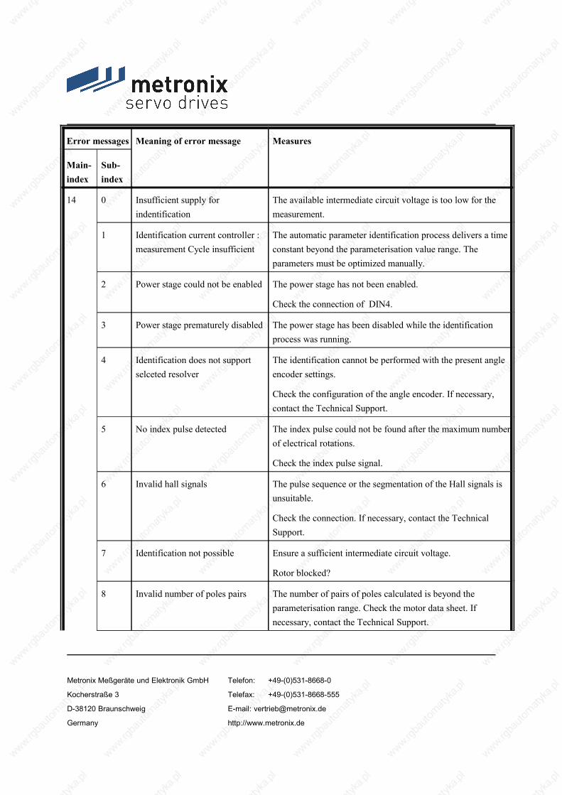
Error messages Meaning of error message Measures
Main-index
Sub-index
14 0 Insufficient supply for indentification
The available intermediate circuit voltage is too low for the measurement.
1 Identification current controller :measurement Cycle insufficient
The automatic parameter identification process delivers a time constant beyond the parameterisation value range. The parameters must be optimized manually.
2 Power stage could not be enabled The power stage has not been enabled.
Check the connection of DIN4.
3 Power stage prematurely disabled The power stage has been disabled while the identification process was running.
4 Identification does not support selceted resolver
The identification cannot be performed with the present angle encoder settings.
Check the configuration of the angle encoder. If necessary, contact the Technical Support.
5 No index pulse detected The index pulse could not be found after the maximum number of electrical rotations.
Check the index pulse signal.
6 Invalid hall signals The pulse sequence or the segmentation of the Hall signals is unsuitable.
Check the connection. If necessary, contact the Technical Support.
7 Identification not possible Ensure a sufficient intermediate circuit voltage.
Rotor blocked?
8 Invalid number of poles pairs The number of pairs of poles calculated is beyond the parameterisation range. Check the motor data sheet. If necessary, contact the Technical Support.
Metronix Meßgeräte und Elektronik GmbH Telefon: +49-(0)531-8668-0
Kocherstraße 3 Telefax: +49-(0)531-8668-555
D-38120 Braunschweig E-mail: [email protected]
Germany http://www.metronix.de

Error messages Meaning of error message Measures
Main-index
Sub-index
9 Automatic parameter identification: General error
Take further information from the additional error data and contact the Technical Support.
15 0 Division by zero Please contact the Technical Support.
1 Out of range error
2 Mathematical underflow
16 0 Errorneous program execution Please contact the Technical Support.
1 Illegal interrupt
2 Initialization error
3 Unexpected state
17 0 Max. following error exceeded Increase error window.
Acceleration parameterization too large
1 Encoder difference control Check the connection of the encoders.
Check the parameterized gear.
18 0 Warning level analogue motor temperature
Motor too hot? Check the parameterization(current controller, current limitation).
Suitable sensor?
Sensor defective?
Error also occurs if sensor is bypassed: device defective.
1 Warning level temperature power stage
Plausible temperature display?
Check the installation conditions, filter mats of fan dirty?
Device fan defective?
21 0 Error 1 current measurement U The error cannot be eliminated by the user. Contact the Technical Support and - if necessary - send the servo
1 Error 1 current measurement V
Metronix Meßgeräte und Elektronik GmbH Telefon: +49-(0)531-8668-0
Kocherstraße 3 Telefax: +49-(0)531-8668-555
D-38120 Braunschweig E-mail: [email protected]
Germany http://www.metronix.de

Error messages Meaning of error message Measures
Main-index
Sub-index
positioning controller to the sales representative.2 Error 2 current measurement U
3 Error 2 current measurement V
22 0 PROFIBUS:Worng initialization
Technology module defective?
Contact the Technical Support.1 PROFIBUS: reserved
2 Communication error PROFIBUS Check the slave address.
Check the bus terminators.
Check the cabling.
3 PROFIBUS:Invalid slave address
The communication was started with slave address 126. Select another slave address.
4 PROFIBUS:Range overflow
Mathematical error during the conversion of physical units. The value range of the data and of the physical units do not match. Contact the Technical Support.
25 0 Invalid device type Technical defect or unsuitable firmware.
Contact the Technical Support and - if necessary - sendthe servo positioning controller to the sales representative.
1 Device type not supported
2 HW revision not supported
3 Device function restricted Contact the Technical Support and - if necessary - sendthe servo positioning controller to the sales representative.
26 0 No user parameter set Load the default parameter set.
If the error continues, contact the Technical Support.
1 Checksum error Please contact the Technical Support.
2 Flash:Error during write-operation
Metronix Meßgeräte und Elektronik GmbH Telefon: +49-(0)531-8668-0
Kocherstraße 3 Telefax: +49-(0)531-8668-555
D-38120 Braunschweig E-mail: [email protected]
Germany http://www.metronix.de

Error messages Meaning of error message Measures
Main-index
Sub-index
3 Flash: Error during erase-operation
4 Flash: Error in internal flash The error cannot be eliminated by the user.
Please contact the technical support team.5 No calibration data
6 Missing user position data sets Simply perform save & reset.
Load the default parameter set.
If the error continues to occur, contact the Technical Support.
7 Faulty data tables (CAM) Load default parameter set, reload the parameter set if necessary.
If the error continues, contact the Technical Support.
27 0 Following error warning level Check the parameterisation of the following error.
Motor blocked?
28 0 Hours-run meter missing Please contact the Technical Support.
1 Hours-run meter: write error
2 Hours-run meter correced Acknowledge the error. If the error continues to occur, contact the Technical Support.
3 Hours-run meter converted
30 0 Internal calculation error Please contact the Technical Support.
31 0 I²t motor Motor blocked?
1 I²t servo controller Check the power rating of the drive package.
2 I²t-PFC Check the power rating of the drive package.
Select operation without PFC?
3 I²t-Break resistor Braking resistor overloaded. Use external braking resistor?
4 I²t real power overload Reduce the real power of the drive
Metronix Meßgeräte und Elektronik GmbH Telefon: +49-(0)531-8668-0
Kocherstraße 3 Telefax: +49-(0)531-8668-555
D-38120 Braunschweig E-mail: [email protected]
Germany http://www.metronix.de

Error messages Meaning of error message Measures
Main-index
Sub-index
32 0 Loading period DC-bus exceeded Please contact the Technical Support.
1 Undervoltage for active PFC
5 Braking chopper overload. Intermediate circuit couldn’t be discharged.
6 Discharge period DC-bus exceeded
7 Failure of Power supply for controller enable
No intermediate circuit voltage.
Angle encoder not ready.
8 Supply power breakdown at controller enable
Interruption / mains failure of power supply.
Check the supply.
9 Phase failure Failure of one or several phases. Check the power supply.
33 0 Following error encoder emulation
Please contact the Technical Support.
34 0 No synchronisation via field bus Failure of synchronization messages from master?
1 Field bus synchronisation error Failure of synchronization messages from master?
Parameterization of synchronization interval too small?
35 0 Speed protection of Linear motor The encoder signals are disturbed. Check the installation for compliance with EMC recommendations.
5 Error during the determination of the commutation position
For this motor an improper method has been chosen. Please contact the Technical Support.
36 0 Parameter limited Check the value range of the parameter stated.
1 Parameter not accepted
Metronix Meßgeräte und Elektronik GmbH Telefon: +49-(0)531-8668-0
Kocherstraße 3 Telefax: +49-(0)531-8668-555
D-38120 Braunschweig E-mail: [email protected]
Germany http://www.metronix.de

Error messages Meaning of error message Measures
Main-index
Sub-index
37 0 ... 9 SERCOS field bus Refer to the SERCOS Manual or contact the Technical Support.
38 0 ... 9 SERCOS field bus Refer to the SERCOS Manual or contact the Technical Support.
39 0 ... 6 SERCOS field bus Refer to the SERCOS Manual or contact the Technical Support.
40 0 Negative SW limit switch The position setpoint has reached or exceeded the respective software limit switch.
Check the target data.
Check the positioning range.
1 Positive SW limit switch
2 Target position behind the negative SW limit switch
The start of a positioning run was suppressed as the target lies beyond the respective software limit switch.
Check the target data.
Check the positioning range.
3 Target position behind the positive SW limit switch
41 0 Course program: Synchronization error
Please contact the Technical Support.
1 Course program: Unknown command
2 Course program: Invalid branch destination
42 0 Positioning: Missing following position: Stop
The positioning target cannot be reached with the current positioning options or the current boundary conditions.
Check the positioning parameters.1 Positioning: Reversing the direction not allowed: Stop
2 Positioning: Reversing the direction not allowed after stop
Metronix Meßgeräte und Elektronik GmbH Telefon: +49-(0)531-8668-0
Kocherstraße 3 Telefax: +49-(0)531-8668-555
D-38120 Braunschweig E-mail: [email protected]
Germany http://www.metronix.de

Error messages Meaning of error message Measures
Main-index
Sub-index
3 Start positioning rejected: wrong mode of operation
The change of the mode of operation could not be performed by the position set.
5 Rotary axis: direction of rotation is not allowed
According to the selected mode of the rotary axis the calculated direction of rotation is not allowed. Check the selected mode.
9 Error at positioning start Speed limitation exceeded or positioning data set inhibited
43 0 Limit switch: Negative setpoint inhibited
The drive has left the intended motion range.
Technical defect in the system?1 Limit switch:
Positive setpoint inhibited
2 Limit switch: Positioning suppressed
45 0 Supply voltage cannot be switched off
Technical defect?
Contact the Technical Support.1 Supply voltage cannot be switched
on
2 Supply voltage was activated
47 0 Timeout (thread mode, Set-up mode)
The speed has not been fallen below the required value for the thread mode (set-up mode) in time. Check the processing of the request by the PLC.
50 0 CAN: Too much synchronous PDOs
Please contact the Technical Support.
1 SDO error occured
60 0 Ethernet user specific (1) Please contact the Technical Support.
61 0 Ethernet user specific (2) Please contact the Technical Support.
Metronix Meßgeräte und Elektronik GmbH Telefon: +49-(0)531-8668-0
Kocherstraße 3 Telefax: +49-(0)531-8668-555
D-38120 Braunschweig E-mail: [email protected]
Germany http://www.metronix.de

Error messages Meaning of error message Measures
Main-index
Sub-index
62 0 EtherCAT: Initialization error No EtherCAT bus available.
1 EtherCAT: Initialization error Error in the hardware.
2 EtherCAT: Protocol error No CAN over EtherCAT are used.
3 EtherCAT: Invalid RPDO length Sync Manager 2: Buffer size too large.
4 EtherCAT: Invalid TPDO length Sync Manager 3: Buffer size too large.
5 EhterCAT: Erroneous cyclic communication
Safety shutdown: Failure of cyclic data transfer.
63 0 EtherCAT: Defective module Error in the hardware.
1 EtherCAT: Invalid data Wrong type of telegram.
2 EtherCAT: TPDO data has not been read
Transmit buffer are full.
3 EtherCAT: No distributed clocks active
Warning: Firmware synchronize system on the telegram not on the Ditributed clocks sytem.
4 Missing SYNC message in IPO cycle
There are no sent telegrams into the IPO time slot.
64 0 .. 6 DeviceNet fieldbus (1) Please contact the Technical Support.
65 0 .. 1 DeviceNet fieldbus (2) Please contact the Technical Support.
70 0 .. 3 FHPP fieldbus Please contact the Technical Support.
71 0 .. 2 FHPP fieldbus Please contact the Technical Support.
80 0 Time overflow current controller IRQ
Please contact the Technical Support.
1 Time Overflow speed controller IRQ
Metronix Meßgeräte und Elektronik GmbH Telefon: +49-(0)531-8668-0
Kocherstraße 3 Telefax: +49-(0)531-8668-555
D-38120 Braunschweig E-mail: [email protected]
Germany http://www.metronix.de

Error messages Meaning of error message Measures
Main-index
Sub-index
2 Time Overflow position controller IRQ
3 Time Overflow interpolator IRQ
81 4 Time overflow low-level IRQ Please contact the Technical Support.
5 Time overflow IRQ-level 5
82 0 Sequencing control Normally just information. No measures required.
83 0 Invalid Technology module Insert the technology module into the other slot, refer to the documentation of the module.
1 Technology module not supported Incorrect firmware?Load the correct firmware.
Contact the Technical Support2 Technology module: HW revision
not supported
3 Technology module: Write error Please contact the Technical Support.
4 Technology module: MC 2000 watchdog
90 0 Missing hardware component (SRAM)
Please contact the Technical Support.
1 Missing hardware component (FLASH)
2 Error during booting of FPGA
3 Error during starting of SD-ADUs
4 Synchronization error SD-ADU after start
5 SD-ADU not synchronous
Metronix Meßgeräte und Elektronik GmbH Telefon: +49-(0)531-8668-0
Kocherstraße 3 Telefax: +49-(0)531-8668-555
D-38120 Braunschweig E-mail: [email protected]
Germany http://www.metronix.de

Error messages Meaning of error message Measures
Main-index
Sub-index
6 Trigger error
7 CAN controller not available
8 Check sum error of device parameter
9 DEBUG-Firmware loaded
91 0 Internal initialisation error Please contact the Technical Support.
Metronix Meßgeräte und Elektronik GmbH Telefon: +49-(0)531-8668-0
Kocherstraße 3 Telefax: +49-(0)531-8668-555
D-38120 Braunschweig E-mail: [email protected]
Germany http://www.metronix.de

11 Technologiemodule
11.1 PROFIBUS-DP-Interface
11.1.1 Product description
The PROFIBUS-DP interface provides an additional field bus connection. All functions and parameters can be addressed directly, e.g. from a Simatic S7 control system. The interface can be plugged into the technology slots TECH1 or TECH2 or the ARS 2300 servo positioning controller.
As a special feature, S7 function blocks have been developed for the drives controllers. Using these function blocks, the drive controllers can be controlled directly by the PLC program and the users can integrate their systems easily and clearly into the Simatic S7 environment.
11.1.2 Technical data
Table 39: Technical data: PROFIBUS-DP interface: Ambient conditions, dimensions and weight
Range Values
Storage temperature range -25 °C to +75°C
Operating temperature range / deratings 0°C to 50°C
Atmospheric humidity 0..90%, non-condensing
Altitude Up to 1000 m above msl
External dimensions (LxWxH): approx. 92 x 65 x 19mmsuitable for technology slot TECH1 or TECH2
Weight: approx. 50g
Metronix Meßgeräte und Elektronik GmbH Telefon: +49-(0)531-8668-0
Kocherstraße 3 Telefax: +49-(0)531-8668-555
D-38120 Braunschweig E-mail: [email protected]
Germany http://www.metronix.de

Table 40: Technical data: PROFIBUS-DP interface: Interfaces and communication
Communication interface Profibus module
Controller Profibus controller VPC3+, 12 Mbaud max.
Protocol Profibus DP,
32-byte telegrams with operating-mode-depending configuration
Interface Floating, D-SUB 9-pin, integrated bus terminating resistors
Special functions Support of diagnosis data, RTS signal led out, fail-safe mode, sync/freeze
The following elements can be found on the front plate of the PROFIBUS-DP interface (see Figure 31):
a green LED to indicate readiness for operation
a 9-pin female DSUB connector
two DIP switches for activating the terminating resistors
Metronix Meßgeräte und Elektronik GmbH Telefon: +49-(0)531-8668-0
Kocherstraße 3 Telefax: +49-(0)531-8668-555
D-38120 Braunschweig E-mail: [email protected]
Germany http://www.metronix.de

Figure 31: PROFIBUS-DP interface: Front view
11.1.3 Pin assignments and cable specifications
11.1.3.1 Pin assignments
9-pin DSUB connector, female
Table 41: Pin assignment: PROFIBUS-DP interface
Pin no. Name Value Specification
1 Shield - Cable shield
Metronix Meßgeräte und Elektronik GmbH Telefon: +49-(0)531-8668-0
Kocherstraße 3 Telefax: +49-(0)531-8668-555
D-38120 Braunschweig E-mail: [email protected]
Germany http://www.metronix.de

6 +5V +5 V +5V output 1)
2 - - Not used
7 - - Not used
3 RxD / TxD-P B-line transmission / reception data
8 RxD / TxD-N A-line transmission / reception data
4 RTS / LWL Request to Send 2)
9 - - Not used
5 GND5V 0 V Reference potential GND 5V 1)
1) Can be used for external bus termination or to supply the transmitter/receiver of an optical waveguide transmission.
2) The signal is optional. It is used to identify the direction of an optical waveguide connection.
11.1.3.2 Mating connector
9-pin DSUB connector, e.g. Erbic MAX Profibus IDC Switch, made by ERNI
11.1.3.3 Cable type and configuration
The cable names given refer to cables made by Lapp. They have proven to be reliable and are successfully used in many applications. However, it is also possible to use comparable cables from other manufacturers, e.g. Lütze or Helukabel.
LAPP KABEL UNITRONIC BUS L2/FIP FC; 1 x 2 x 0.64; ∅ 7.8 mm,with tinned CU shieldingfor quick-connect applications with IDC connectors
For highly flexible applications:
Metronix Meßgeräte und Elektronik GmbH Telefon: +49-(0)531-8668-0
Kocherstraße 3 Telefax: +49-(0)531-8668-555
D-38120 Braunschweig E-mail: [email protected]
Germany http://www.metronix.de

LAPP KABEL UNITRONIC BUS-FD P L2/FIP; 1 x 2 x 0.64; ∅ 8 mm,with tinned CU shieldingfor highly flexible use in drag chains
11.1.4 Termination and bus terminating resistors
Every bus segment of a PROFIBUS network has to be equipped with bus terminating resistors to minimise line reflections and to adjust a defined rest potential on the line. The bus termination has to be provided at the beginning and at the end of every bus segment.
Most PROFIBUS connectors come supplied with integrated terminating resistors. For bus connections with connectors without integrated terminating resistors, the PROFIBUS-DP interface has its own terminating resistors. They can be activated with the help of the two DIP switches on the module (switch set to ON).
To ensure safe operation of the network, only one bus termination may be used at a time.
The external connection can also be set up discretely (see Figure 34). The power supply of 5 V required for the externally connected terminating resistors is supplied at the PROFIBUS connector of the PROFIBUS-DP interface (see pin assignment in Table 41).
GND 5V
+5V
A-LineB-Line
390 Ohm
220 Ohm
390 Ohm
Figure 32: PROFIBUS-DP interface: Connection with external terminating resistors
Metronix Meßgeräte und Elektronik GmbH Telefon: +49-(0)531-8668-0
Kocherstraße 3 Telefax: +49-(0)531-8668-555
D-38120 Braunschweig E-mail: [email protected]
Germany http://www.metronix.de

11.2 SERCOS module
11.2.1 Product description
The SERCOS module is used to connect the ARS 2300 servo positioning controller to a SERCOS-compatible CNC control. The communication on the SERCOS bus uses a ring-shaped optical fibre link with transmission rates of up to 16 Mbaud. If six servo positioning controllers are connected to one bus, setpoints and actual values (position, speed and torque values) can be exchanged with the CNC control every 500 µs.
A special feature of the SERCOS bus is the synchronisation of all the devices connected to the bus. If several ARS 2000 servo positioning controllers are connected, the internal controllers and output stages of the servo positioning controllers operate in a phase-locked manner.
The SERCOS module can only be used in technlogy slot TECH2.
11.2.2 Technical data
Table 42: Technical data: SERCOS module: Ambient conditions, dimensions and weight
Range Values
Storage temperature range -25 °C to +75°C
Operating temperature range / deratings 0°C to 50°C
Atmospheric humidity 0..90%, non-condensing
Altitude up to 1000 m above msl
External dimensions (LxWxH): approx. 92 x 65 x 19mmsuitable for technology slot TECH2
Weight approx. 50g
The following elements can be found on the front plate of the SERCOS module (see Figure 33)
a green LED to indicate that the bus is ready for operation
Metronix Meßgeräte und Elektronik GmbH Telefon: +49-(0)531-8668-0
Kocherstraße 3 Telefax: +49-(0)531-8668-555
D-38120 Braunschweig E-mail: [email protected]
Germany http://www.metronix.de

a connection for the optical waveguide receiver / type HFD 7000-402 (metal connection)
a connection for the optical waveguide transmitter / type HFD 7000-210 (plastic connection)
Figure 33: SERCOS module: Front view
11.2.3 Optical waveguide specification
More information concerning the type and setup of suitable optical waveguides can be found in the standard SERCOS literature, e.g.:
http://www.sercos.org/
Interests Group SERCOS interface e.V.Landhausstrasse 20, 70190 Stuttgart
Germany
Metronix Meßgeräte und Elektronik GmbH Telefon: +49-(0)531-8668-0
Kocherstraße 3 Telefax: +49-(0)531-8668-555
D-38120 Braunschweig E-mail: [email protected]
Germany http://www.metronix.de

11.3 EA88 interface technology module
11.3.1 Product description
The EA88 interface can be used in technology slot TECH1 or TECH2 of the ARS 2300 servo positioning controller to extend the already existing digital IOs. Up to two EA88 interfaces can be supported simultaneously.
This technology module can be used to actuate up to 8 digital 24V outputs independently. In addition, 8 digital 24V inputs are available.
The EA88 interface has the following characteristics:
Digital 24V inputs
Digital 24V outputs which can be activated separately and loaded with 100 mA each
MicroCombicon pin-and-socket connectors made by PHOENIX
Pin-and-socket connectors via male multipoint connector in accordance with DIN 41612
The inputs and outputs are floating due to the optocouplers
The inputs and outputs are protected against short circuits and overload
11.3.2 Technical data
11.3.2.1 General data
Metronix Meßgeräte und Elektronik GmbH Telefon: +49-(0)531-8668-0
Kocherstraße 3 Telefax: +49-(0)531-8668-555
D-38120 Braunschweig E-mail: [email protected]
Germany http://www.metronix.de

Table 43: Technical data: EA88 interface
Range Values
Storage temperature range -25 °C to +75°C
Operating temperature range / deratings 0°C to 50°C
Atmospheric humidity 0..90%, non-condensing
Altitude Up to 1000 m above msl
External dimensions (LxWxH): 87mm x 65mm x 19mm; suitable for technology slot
Weight: approx. 50g
11.3.2.2 Digital inputs
8 digital inputs 24V, protected against inverse polarity and short-circuit-proof.
Table 44: Digital inputs [X21]: EA88 interface
Parameter Values
Input High level switches the input
Nominal voltage 24 VDC
Voltage range -30 V...30 V
"High" detection at UEin > 8 V
"Low" detection at UEin < 2 V
Metronix Meßgeräte und Elektronik GmbH Telefon: +49-(0)531-8668-0
Kocherstraße 3 Telefax: +49-(0)531-8668-555
D-38120 Braunschweig E-mail: [email protected]
Germany http://www.metronix.de

Parameter Values
Hysteresis >1V
Input impedance ≥ 4.7 kΩ
Inverse polarity protection Up to -30V
Switching delay up to port pin (low-high transition) < 100 µs
11.3.2.3 Digital outputs
8 digital outputs 24V, protected against inverse polarity and short-circuit-proof, protection against thermal overload.
Table 45: Digital outputs [X22]: EA88 interface
Parameter Values
Switch type High-side switch
Nominal voltage 24 VDC
Voltage range 18 V...30 V
Output current (nominal) IL,nominal = 100 mA
Voltage loss at IL,nominal ≤ 1 V
Residual current with switch in OFF position < 100 µA
Protection against short-circuit / overcurrent > 500mA (approx. value)
Temperature protection Shut-down if the temperature is too high, TJ > 150°
Supply Protection in the case of inductive loads and voltage supply via the output, also if the supply is turned off
Loads R > 220 Ω; L at random; C < 10nF
Switching delay as of port pin < 100 µs
11.3.3 Pin assignment and cable specifications
Metronix Meßgeräte und Elektronik GmbH Telefon: +49-(0)531-8668-0
Kocherstraße 3 Telefax: +49-(0)531-8668-555
D-38120 Braunschweig E-mail: [email protected]
Germany http://www.metronix.de

11.3.3.1 Power supply
The admissible input voltage range during operation is 15VDC….32VDC.
The digital outputs of the EA88 technology module are supplied with voltage exclusively by an external 24VDC power supply. The nominal input voltage for the I/O supply is 24VDC.
If digital inputs are used, the reference potential GND24V of the 24VDC supply also has to be connected to the EA88 interface technology module
11.3.3.2 Pin assignments
The following elements can be found on the front plate of the EA88 interface:
Connector [X21] for 8 digital inputs: PHOENIX MicroCombicon MC 0.5/9-G-2.5 (9-pin type)
Table 46: EA88: Connector [X21] for 8 digital inputs
Pin 1 2 3 4 5 6 7 8 9
Signal GND 24V
In 1 In 2 In 3 In 4 In 5 In 6 In 7 In 8
Connector [X22] for 8 digital outputs: PHOENIX MicroCombicon MC 0.5/10-G-2.5 (10-pin type)
Table 47: EA88: Connector [X22] for 8 digital outputs
Pin 1 2 3 4 5 6 7 8 9 10
Signal GND 24V
Out 1 Out 2 Out 3 Out 4 Out 5 Out 6 Out 7 Out 8 +24VDCexternal
The following Figure 34 shows the position of the connectors and their numbering:
Metronix Meßgeräte und Elektronik GmbH Telefon: +49-(0)531-8668-0
Kocherstraße 3 Telefax: +49-(0)531-8668-555
D-38120 Braunschweig E-mail: [email protected]
Germany http://www.metronix.de
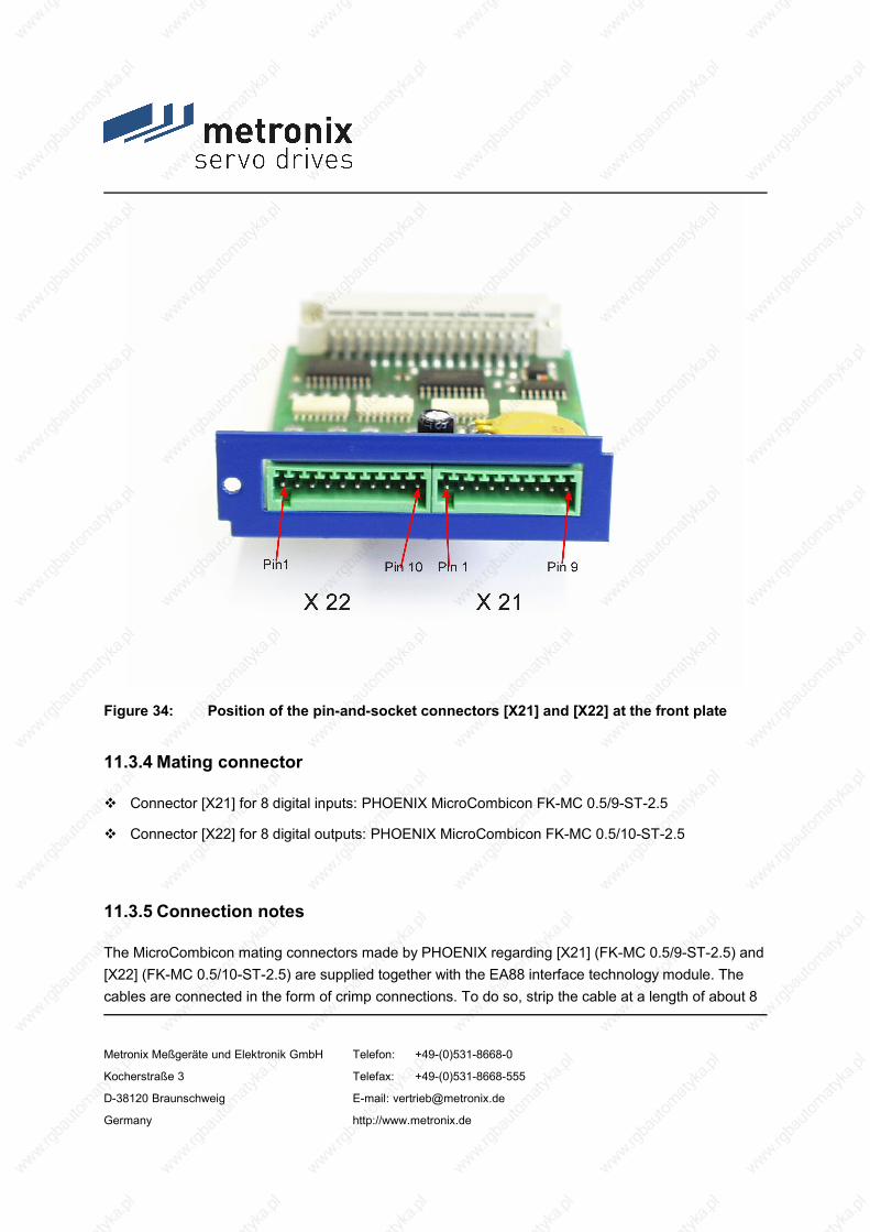
Figure 34: Position of the pin-and-socket connectors [X21] and [X22] at the front plate
11.3.4 Mating connector
Connector [X21] for 8 digital inputs: PHOENIX MicroCombicon FK-MC 0.5/9-ST-2.5
Connector [X22] for 8 digital outputs: PHOENIX MicroCombicon FK-MC 0.5/10-ST-2.5
11.3.5 Connection notes
The MicroCombicon mating connectors made by PHOENIX regarding [X21] (FK-MC 0.5/9-ST-2.5) and [X22] (FK-MC 0.5/10-ST-2.5) are supplied together with the EA88 interface technology module. The cables are connected in the form of crimp connections. To do so, strip the cable at a length of about 8
Metronix Meßgeräte und Elektronik GmbH Telefon: +49-(0)531-8668-0
Kocherstraße 3 Telefax: +49-(0)531-8668-555
D-38120 Braunschweig E-mail: [email protected]
Germany http://www.metronix.de

mm. Then insert it into the desired opening by pressing down the orange crimp lock using a suitable screwdriver, the tip of a ball-pen or something similar. Release the lock to fix the cable in place. The maximum admissible wire cross-section (wire gauge) is 0.5 mm2 or AWG20.
If the EA88 interface is also used to control digital outputs, an additional external 24V supply voltage has to be connected to [X22], pin 10.
As the lines GND24V and +24Vext. have to transfer the entire current of all outputs connected, their cross-section has to be sized accordingly (recommended: AWG 20).
Metronix Meßgeräte und Elektronik GmbH Telefon: +49-(0)531-8668-0
Kocherstraße 3 Telefax: +49-(0)531-8668-555
D-38120 Braunschweig E-mail: [email protected]
Germany http://www.metronix.de

11.4 MC 2000 „Drive-In“ 4-Axis Motion Coordinator
11.4.1 Product description
The technology module MC 2000 motion coordinator can control up to four multi coordinated servo axis from the ARS 2000 servo drive. With the MC 2000 complex motion control can be realised fast and easy, e. g.
Electronic cam drives and gears
Joint axis
Point-to-point positioning
Several types for interpolation (Interpolation, Circular Interpolation, Helical Interpolation).
Simply insert the MC 2000 module into the ARS 2000. As the MC 2000 master, it can control up to three additional ARS 2000 servo drive slaves via CANopen DSP402. An external encoder can be connected directly to ARS 2000 and be software configured as an additional axis for the MC 2000.
Therefore, all available I/Os in the ARS 2000 can be used. In addition, the ARS 2000 can be expanded by using the I/O module EA88. A second CAN-interface is available for external CAN I/O via the master.
Metronix Meßgeräte und Elektronik GmbH Telefon: +49-(0)531-8668-0
Kocherstraße 3 Telefax: +49-(0)531-8668-555
D-38120 Braunschweig E-mail: [email protected]
Germany http://www.metronix.de

Figure 35: MC 2000 4-Axis Motion Coordinator
11.4.2 Features
11.4.2.1 Compact
Plug-in MC 2000 module directly into ARS 2000 servo drive
Controls up to 4 servo axis
Easy wiring via CAN-bus
Metronix Meßgeräte und Elektronik GmbH Telefon: +49-(0)531-8668-0
Kocherstraße 3 Telefax: +49-(0)531-8668-555
D-38120 Braunschweig E-mail: [email protected]
Germany http://www.metronix.de

Figure 36: MC 2000 4-Axis Motion Coordinator maximum capacity
11.4.2.2 Fast
1 ms cycle time with up to 4 servo axis
Short start up time with Trio Motion BASIC software with a wide scope of BASIC language commands and motion control functions
High-speed sample input for fast measuring and interpretation of actual values
11.4.2.3 Easy
User programming with the established Trio Motion “Motion Perfect” software
Program generation of complex motion sequences like camming, gearing and interpolated multi axis movements
Integrated module minimizes external wiring
Metronix Meßgeräte und Elektronik GmbH Telefon: +49-(0)531-8668-0
Kocherstraße 3 Telefax: +49-(0)531-8668-555
D-38120 Braunschweig E-mail: [email protected]
Germany http://www.metronix.de

11.4.3 Techical data
Table 48: Technical data: MC 2000 4-Axis Motion CoordinatorSize (L x B x H) 92 mm x 65 mm x 19 mmTemperature range 0° C bis 50° C
Current consumption Max. 350 mA / 3,3 VDC and 150 mA / 5 VDC(intern via servo positioning controller ARS 2000)
Max. number of axis 8 (4x servo drives, 1x encoder, 3x virtual)Servo cycle time 1 msBuilt-in digital inputs 6x 24 VDC (via servo positioning controller ARS 2000)Built-in digital outputs 3x 24 VDC (via servo positioning controller ARS 2000)
Built-in analogue inputs 3x ±10 VDC via servo positioning controller ARS 2000(1x 16 Bit differential and 2x 10 Bit single ended)
Built-in analogue outputs 2 x ±10 VDC, 9 Bit (via servo positioning controller ARS 2000)Serial ports 1x RS232 (programming) + 1x RS485 (e.g. HMI)
CAN Ports 2x CAN Interfaces (1x Remote Drives max. 1 Mbaud and1x Remote CAN max. 500 kBaud)
Optional External I/O module (8 digital IN, 8 digtal OUT,via servo positioning controller ARS 2000)
User memory 512 kBytes Table memory 32000 valuesMulti-tasking 2 Fast-Tasks + 5 Normal-TasksEMC Compliance EN 61800-3Order number 9200-0008-00
Metronix Meßgeräte und Elektronik GmbH Telefon: +49-(0)531-8668-0
Kocherstraße 3 Telefax: +49-(0)531-8668-555
D-38120 Braunschweig E-mail: [email protected]
Germany http://www.metronix.de

11.5 General installation notes for technology modules
DANGER !
Prior to installing technology modules, the ARS 2300 servo positioning controller has to be disconnected from any current-carrying conductors. After the operating voltage has been disconnected, wait for 5 minutes so that the capacities in the ARS 2300 servo positioning controller can be completely discharged.
Make sure that ESD protection measures are taken when handling technology modules.
Remove the front plate above the technology slot of the ARS 2300 servo positioning controller using a suitable screwdriver. Then push the technology module into the open technology slot such that the circuit board is held by the lateral guides of the technology slot. Push the technology module in until it reaches the stop. Then screw technology module onto the housing of the servo positioning controller using the Phillips screw. Make sure that the front plate has conducting contact with the housing of the servo positioning controller (PE).
Metronix Meßgeräte und Elektronik GmbH Telefon: +49-(0)531-8668-0
Kocherstraße 3 Telefax: +49-(0)531-8668-555
D-38120 Braunschweig E-mail: [email protected]
Germany http://www.metronix.de