Embed Size (px)
Citation preview
R1.0
Datasheet RCUXXYYEAE KNX Room Control Unit
www.eaetechnology.com
Datasheet RCUXXYYEAE KNX Room Control Unit
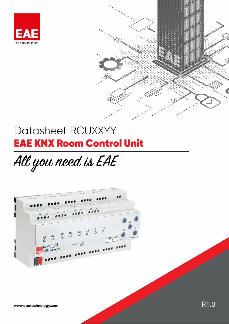
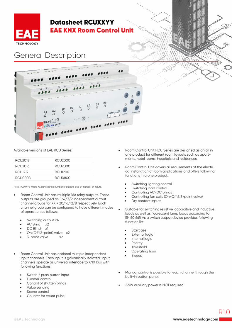
General Description
Available versions of EAE RCU Series:
RCU2018 RCU2000
RCU2016 RCU2000
RCU1212 RCU1200
RCU0808 RCU0800
Note: RCUXXYY where XX denotes the number of outputs and YY number of inputs.
• Room Control Unit has multiple 16A relay outputs. These outputs are grouped as 5/4/3/2 independent output channel groups for XX = 20/16/12/8 respectively. Each channel group can be configured to have different modes of operation as follows;
• Switching output x4• AC Blind x2• DC Blind x1• On/Off (2-point) valve x2• 3-point valve x2
• Room Control Unit has optional multiple independent input channels. Each input is galvanically isolated. Input channels operate as universal interface to KNX bus with following functions;
• Switch / push button input • Dimmer control • Control of shutter/blinds • Value sending • Scene control • Counter for count pulse
• Room Control Unit RCU Series are designed as an all in one product for different room layouts such as apart-ments, hotel rooms, hospitals and residences.
• Room Control Unit covers all requirements of the electri-cal installation of room applications and offers following functions in a one product.
• Switching lighting control• Switching load control• Controlling AC/DC blinds• Controlling fan coils (On/Off & 3-point valve)• Dry contact inputs
• Suitable for switching resistive, capacitive and inductive loads as well as fluorescent lamp loads according to EN 60 669. As a switch output device provides following function list,
• Staircase • External logic • Internal logic • Priority • Threshold • Operating hour• Sweep
• Manual control is possible for each channel through the built-in button panel.
• 220V auxiliary power is NOT required.
www.eaetechnology.com©EAE Technology
R1.0
Datasheet RCUXXYYEAE KNX Room Control Unit
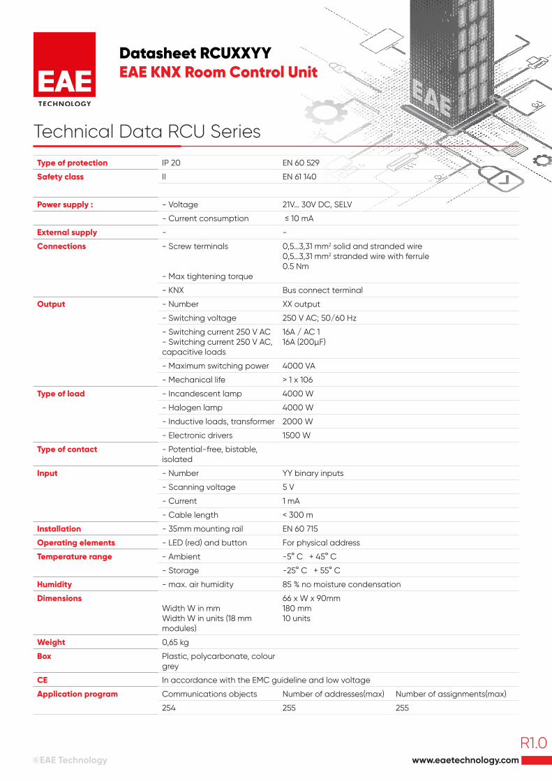
Technical Data RCU Series
Type of protection IP 20 EN 60 529
Safety class II EN 61 140
Power supply : - Voltage 21V… 30V DC, SELV
- Current consumption ≤ 10 mA
External supply - -
Connections - Screw terminals
- Max tightening torque
0,5…3,31 mm2 solid and stranded wire 0,5…3,31 mm2 stranded wire with ferrule0.5 Nm
- KNX Bus connect terminal
Output - Number XX output
- Switching voltage 250 V AC; 50/60 Hz
- Switching current 250 V AC- Switching current 250 V AC, capacitive loads
16A / AC 116A (200µF)
- Maximum switching power 4000 VA
- Mechanical life > 1 x 10⁶
Type of load - Incandescent lamp 4000 W
- Halogen lamp 4000 W
- Inductive loads, transformer 2000 W
- Electronic drivers 1500 W
Type of contact - Potential-free, bistable, isolated
Input - Number YY binary inputs
- Scanning voltage 5 V
- Current 1 mA
- Cable length < 300 m
Installation - 35mm mounting rail EN 60 715
Operating elements - LED (red) and button For physical address
Temperature range - Ambient -5° C + 45° C
- Storage -25° C + 55° C
Humidity - max. air humidity 85 % no moisture condensation
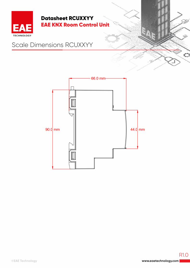
DimensionsWidth W in mm Width W in units (18 mm modules)
66 x W x 90mm180 mm10 units
Weight 0,65 kg
Box Plastic, polycarbonate, colour grey
CE In accordance with the EMC guideline and low voltage
Application program Communications objects Number of addresses(max) Number of assignments(max)
254 255 255
www.eaetechnology.com©EAE Technology
R1.0
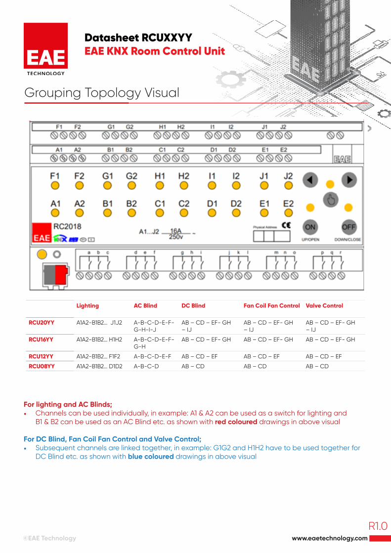
Lighting AC Blind DC Blind Fan Coil Fan Control Valve Control
RCU20YY A1A2-B1B2… J1J2 A-B-C-D-E-F-G-H-I-J
AB – CD – EF- GH – IJ
AB – CD – EF- GH – IJ
AB – CD – EF- GH – IJ
RCU16YY A1A2-B1B2… H1H2 A-B-C-D-E-F-G-H
AB – CD – EF- GH AB – CD – EF- GH AB – CD – EF- GH
RCU12YY A1A2-B1B2… F1F2 A-B-C-D-E-F AB – CD – EF AB – CD – EF AB – CD – EF
RCU08YY A1A2-B1B2… D1D2 A-B-C-D AB – CD AB – CD AB – CD
For lighting and AC Blinds;• Channels can be used individually, in example: A1 & A2 can be used as a switch for lighting and
B1 & B2 can be used as an AC Blind etc. as shown with red coloured drawings in above visual
For DC Blind, Fan Coil Fan Control and Valve Control;• Subsequent channels are linked together, in example: G1G2 and H1H2 have to be used together for
DC Blind etc. as shown with blue coloured drawings in above visual
Datasheet RCUXXYYEAE KNX Room Control Unit
Grouping Topology Visual
www.eaetechnology.com©EAE Technology
R1.0
Datasheet RCUXXYYEAE KNX Room Control Unit
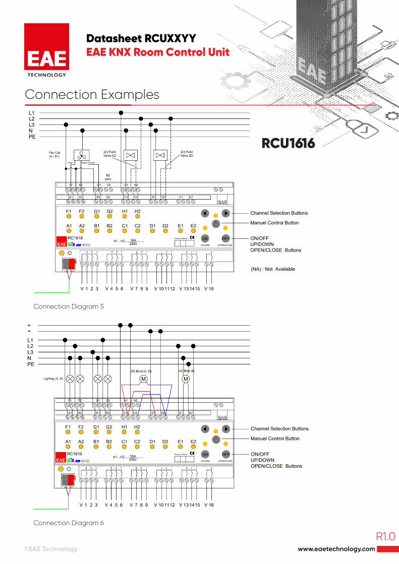
Connection Examples
RCU1616
Connection Diagram 5
Connection Diagram 6
www.eaetechnology.com©EAE Technology
R1.0
Datasheet RCUXXYYEAE KNX Room Control Unit
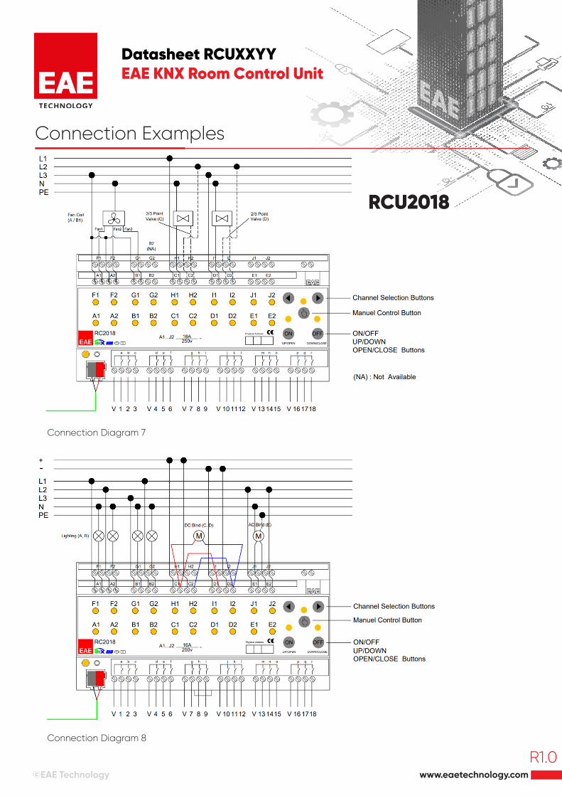
Connection Examples
RCU2018
Connection Diagram 7
Connection Diagram 8
www.eaetechnology.com©EAE Technology
R1.0
Datasheet RCUXXYYEAE KNX Room Control Unit
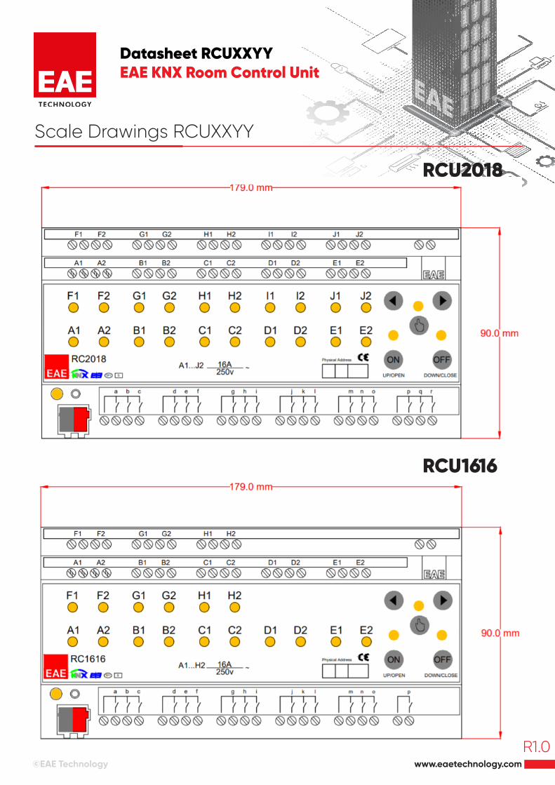
Scale Drawings RCUXXYY
RCU2018
RCU1616
www.eaetechnology.com©EAE Technology
R1.0
Datasheet RCUXXYYEAE KNX Room Control Unit
Scale Dimensions RCUXXYY
www.eaetechnology.com©EAE Technology
R1.0