Embed Size (px)
Citation preview
Datasheet: QCI-DS031 QuickSilver Controls, Inc. Date: 20 September 2017 www.QuickSilverControls.com
Property of QuickSilver Controls, Inc. Page 1 of 15 This document is subject to change without notice. QuickControl® and QCI® are Registered Trademarks of QuickSilver Controls, Inc. SilverMax™, Mosolver™, SilverLode™, SilverNugget™, SilverDust™, SilverSterling™, PVIA™, QuickSilver Controls™, and AntiHunt™ are trademarks of QuickSilver Controls, Inc.
SilverNugget™ N2-IX The SilverNugget N2-IX is a servo controller/driver for QCI’s line of NEMA 11, 17, 23, and 24 frame, high torque, direct drive, servo motors. The N2-IX Servo Controller/Driver is designed to operate QCI’s I-Grade motors through a single motor interface cable, which carries motor power and encoder feedback. This single cable solution allows for easy installations and simple cable routing. Power, communications, and I/O are accessed through a single DB15 high density interface connector. The interface includes 7 I/O, all of which support both LVTTL and analog signals, and one of which also supports 0 to 10v analog. A hardware drive enable is available as a factory option. All 7 I/O also have soft configurable pull-up/pull-down resistors, which may also be disabled, for more flexibility. Requires QuickControl v6.22 or greater to initialize and program controller.
Datasheet:QCI-DS031 QuickSilver Controls, Inc.
QuickSilver Controls, Inc. Page 2 of 15
System Overview Point-to-Point Moves
• Relative or Absolute
• Velocity or Time Based
• S-Curve Advanced Motion Profile Moves
• Profile Move Commands
• Register Based o Position o Accel/Decel o Velocity o Modify On-the-Fly o Non-zero velocity start & stop
Input/Output
• 7 LVTTL Digital I/O o Bi-Directional o Set While In Motion
• 7 Analog Inputs (Joystick)
• 1 Analog 0-10v Input
• 1 Output supports PWM out
• 1 Input supports PWM in
• Programmable Logic Switch out
• Secondary Encoder In
• Encoder Out (single ended and differential)
• Driver Enable/Disable Option Program and Data Storage
• 32K Non-Volatile Memory:
• 2000-3000 Program Lines
• User Data Examples o CAM Tables o Motion Profiles o Lookup Tables
Electronic Gearing/Camming
• Follow External Signals o Encoder (A/B Quadrature) o Step and Direction
• Gearing plus Trapezoid motion
• Electronic Cam o Import Cam Table from File
• Gearing with extended precision: o A/B gearing o xxx.xxxxxxxx multiplier
(8 places behind decimal point)
Electronic Slip Clutch/Brake
• Variable Torque
• Wind/Unwind Applications
• Communications
• RS-485 (ASCII, Modbus®, DMX, 9-bit)
• Up To 230K Baud
• Host Control While Servo in Motion Programming Language
• Easy, Menu Driven Interface
• Command Parameter Prompts
• No Syntax Error
• User Namable I/O and Registers Advance PVIA™ Servo Loop
• Improvement Stability
• Simulated Viscous Inertial Damper
• 100:1 Inertial Mismatch
• Direct Drive Oversized Inertial Loads o Flywheels o Belt Drives o Typically eliminates need for
Gearheads Anti-Hunt™
• Optionally transition to open loop while in position – automatically changes back to full servo if position is disturbed.
• No Servo Dither While at Rest Multi-Task/Multi-Thread
• Two programs plus a motion simultaneously
• Multiple background protection settings
Compatible with QCI’s Hybrid Servo Motors
• NEMA 11 Frame o 4000 Counts/Rev Encoder o Up to 9 oz-in (continuous)
• NEMA 17 Frame o 8000 Counts/Rev Encoder o Up to 43 oz-in (continuous) o IP50 or IP65
• NEMA 23 Frame o 8000 Counts/Rev Encoder o Up to 190 oz-in (continuous) o IP50 or IP65
• NEMA 24 Frame o 8000 Counts/Rev Encoder o Up to 330 oz-in (continuous) o IP50 or IP65
Datasheet:QCI-DS031 QuickSilver Controls, Inc.
QuickSilver Controls, Inc. Page 3 of 15
Electrical Specifications
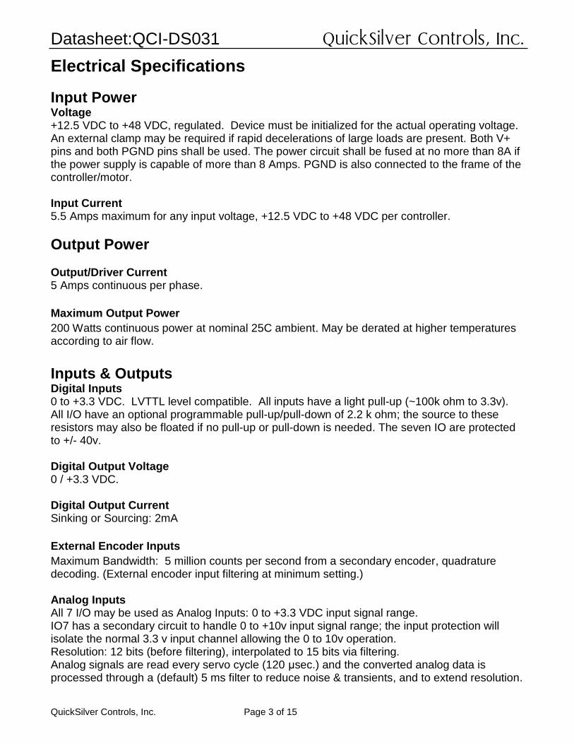
Input Power Voltage +12.5 VDC to +48 VDC, regulated. Device must be initialized for the actual operating voltage. An external clamp may be required if rapid decelerations of large loads are present. Both V+ pins and both PGND pins shall be used. The power circuit shall be fused at no more than 8A if the power supply is capable of more than 8 Amps. PGND is also connected to the frame of the controller/motor. Input Current 5.5 Amps maximum for any input voltage, +12.5 VDC to +48 VDC per controller.
Output Power Output/Driver Current 5 Amps continuous per phase.
Maximum Output Power
200 Watts continuous power at nominal 25C ambient. May be derated at higher temperatures according to air flow.
Inputs & Outputs Digital Inputs 0 to +3.3 VDC. LVTTL level compatible. All inputs have a light pull-up (~100k ohm to 3.3v). All I/O have an optional programmable pull-up/pull-down of 2.2 k ohm; the source to these resistors may also be floated if no pull-up or pull-down is needed. The seven IO are protected to +/- 40v. Digital Output Voltage 0 / +3.3 VDC. Digital Output Current Sinking or Sourcing: 2mA
External Encoder Inputs
Maximum Bandwidth: 5 million counts per second from a secondary encoder, quadrature decoding. (External encoder input filtering at minimum setting.) Analog Inputs All 7 I/O may be used as Analog Inputs: 0 to +3.3 VDC input signal range. IO7 has a secondary circuit to handle 0 to +10v input signal range; the input protection will isolate the normal 3.3 v input channel allowing the 0 to 10v operation. Resolution: 12 bits (before filtering), interpolated to 15 bits via filtering. Analog signals are read every servo cycle (120 μsec.) and the converted analog data is processed through a (default) 5 ms filter to reduce noise & transients, and to extend resolution.
Datasheet:QCI-DS031 QuickSilver Controls, Inc.
QuickSilver Controls, Inc. Page 4 of 15
Communications
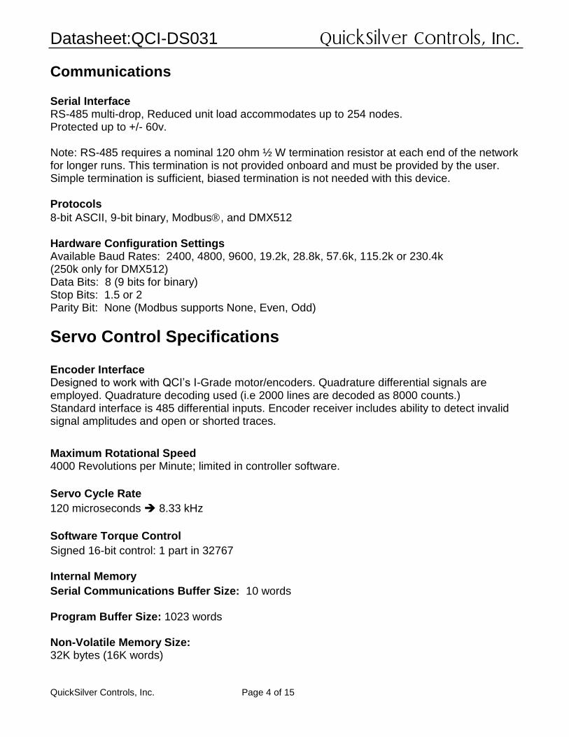
Serial Interface RS-485 multi-drop, Reduced unit load accommodates up to 254 nodes. Protected up to +/- 60v. Note: RS-485 requires a nominal 120 ohm ½ W termination resistor at each end of the network for longer runs. This termination is not provided onboard and must be provided by the user. Simple termination is sufficient, biased termination is not needed with this device. Protocols
8-bit ASCII, 9-bit binary, Modbus, and DMX512 Hardware Configuration Settings Available Baud Rates: 2400, 4800, 9600, 19.2k, 28.8k, 57.6k, 115.2k or 230.4k (250k only for DMX512) Data Bits: 8 (9 bits for binary) Stop Bits: 1.5 or 2 Parity Bit: None (Modbus supports None, Even, Odd)
Servo Control Specifications Encoder Interface Designed to work with QCI’s I-Grade motor/encoders. Quadrature differential signals are employed. Quadrature decoding used (i.e 2000 lines are decoded as 8000 counts.) Standard interface is 485 differential inputs. Encoder receiver includes ability to detect invalid signal amplitudes and open or shorted traces.
Maximum Rotational Speed 4000 Revolutions per Minute; limited in controller software.
Servo Cycle Rate
120 microseconds 8.33 kHz
Software Torque Control
Signed 16-bit control: 1 part in 32767 Internal Memory
Serial Communications Buffer Size: 10 words Program Buffer Size: 1023 words Non-Volatile Memory Size: 32K bytes (16K words)
Datasheet:QCI-DS031 QuickSilver Controls, Inc.
QuickSilver Controls, Inc. Page 5 of 15
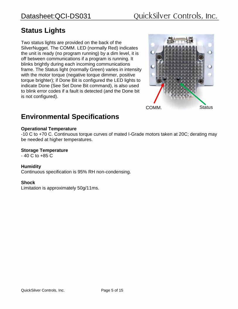
Status Lights Two status lights are provided on the back of the SilverNugget. The COMM. LED (normally Red) indicates the unit is ready (no program running) by a dim level, it is off between communications if a program is running. It blinks brightly during each incoming communications frame. The Status light (normally Green) varies in intensity with the motor torque (negative torque dimmer, positive torque brighter); if Done Bit is configured the LED lights to indicate Done (See Set Done Bit command), is also used to blink error codes if a fault is detected (and the Done bit is not configured).
Environmental Specifications Operational Temperature -10 C to +70 C. Continuous torque curves of mated I-Grade motors taken at 20C; derating may be needed at higher temperatures. Storage Temperature - 40 C to +85 C Humidity Continuous specification is 95% RH non-condensing. Shock Limitation is approximately 50g/11ms.
COMM. Status
Datasheet:QCI-DS031 QuickSilver Controls, Inc.
QuickSilver Controls, Inc. Page 6 of 15
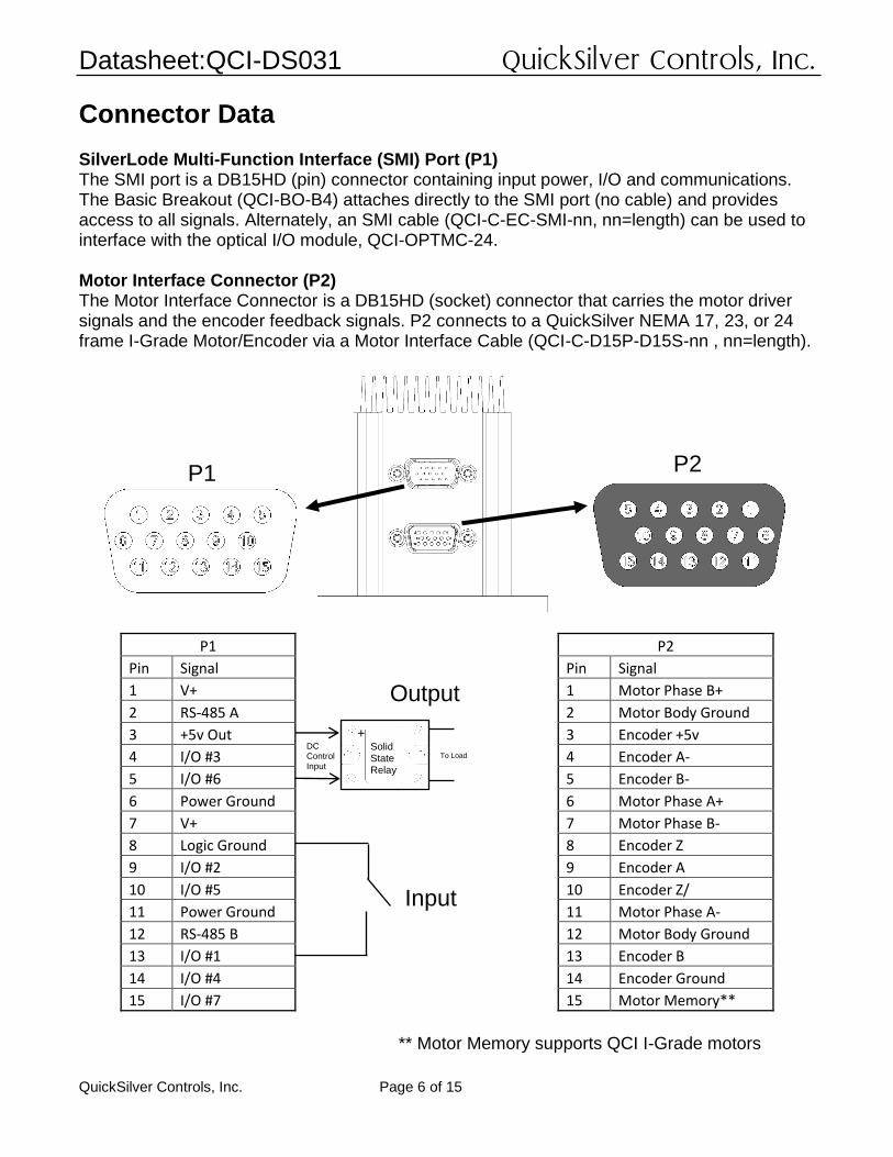
Connector Data SilverLode Multi-Function Interface (SMI) Port (P1) The SMI port is a DB15HD (pin) connector containing input power, I/O and communications. The Basic Breakout (QCI-BO-B4) attaches directly to the SMI port (no cable) and provides access to all signals. Alternately, an SMI cable (QCI-C-EC-SMI-nn, nn=length) can be used to interface with the optical I/O module, QCI-OPTMC-24. Motor Interface Connector (P2) The Motor Interface Connector is a DB15HD (socket) connector that carries the motor driver signals and the encoder feedback signals. P2 connects to a QuickSilver NEMA 17, 23, or 24 frame I-Grade Motor/Encoder via a Motor Interface Cable (QCI-C-D15P-D15S-nn , nn=length).
P1
P2
Pin Signal
Pin Signal
1 V+
1 Motor Phase B+
2 RS-485 A
2 Motor Body Ground
3 +5v Out
3 Encoder +5v
4 I/O #3
4 Encoder A-
5 I/O #6
5 Encoder B-
6 Power Ground
6 Motor Phase A+
7 V+
7 Motor Phase B-
8 Logic Ground
8 Encoder Z
9 I/O #2
9 Encoder A
10 I/O #5
10 Encoder Z/
11 Power Ground
11 Motor Phase A-
12 RS-485 B
12 Motor Body Ground
13 I/O #1
13 Encoder B
14 I/O #4
14 Encoder Ground
15 I/O #7
15 Motor Memory**
P1 P2
Input
Output
** Motor Memory supports QCI I-Grade motors
Solid State Relay
DC Control Input
To Load
+
Datasheet:QCI-DS031 QuickSilver Controls, Inc.
QuickSilver Controls, Inc. Page 7 of 15
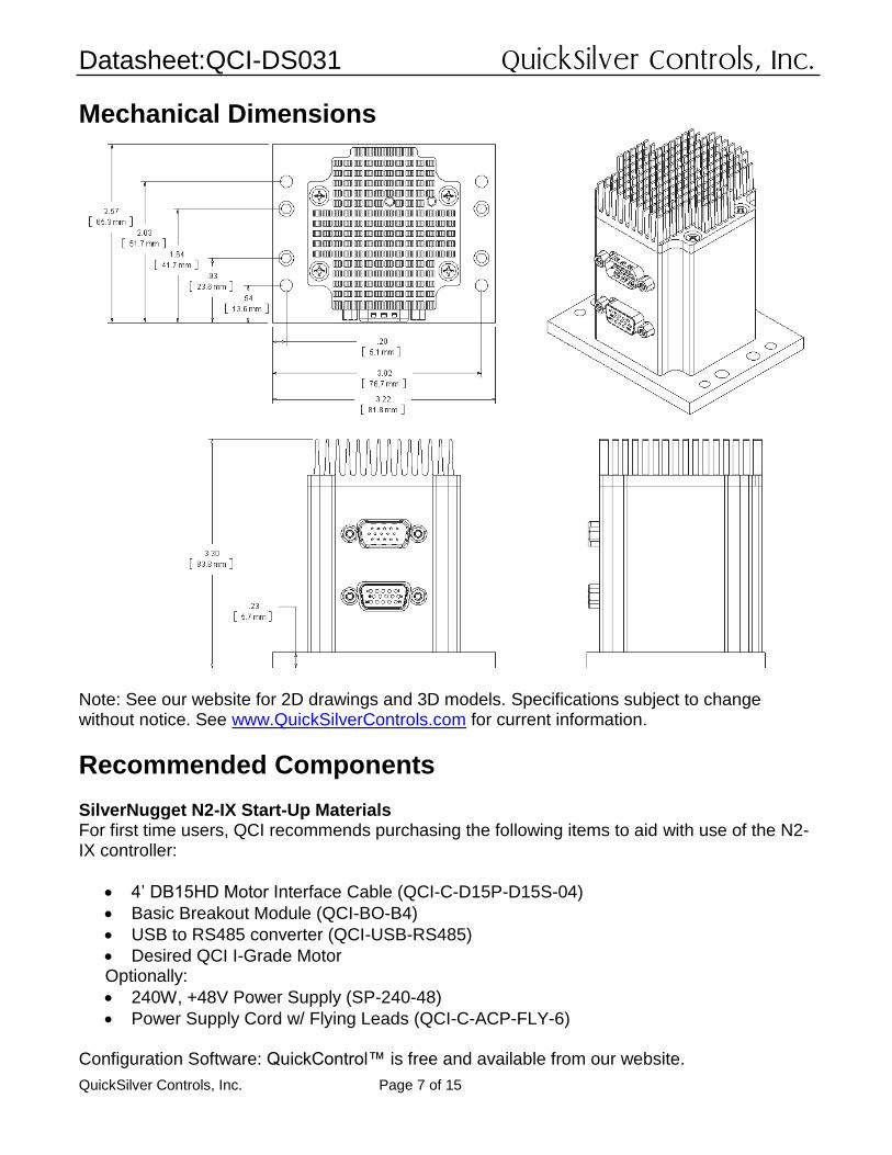
Mechanical Dimensions
Note: See our website for 2D drawings and 3D models. Specifications subject to change without notice. See www.QuickSilverControls.com for current information.
Recommended Components SilverNugget N2-IX Start-Up Materials For first time users, QCI recommends purchasing the following items to aid with use of the N2-IX controller:
• 4’ DB15HD Motor Interface Cable (QCI-C-D15P-D15S-04)
• Basic Breakout Module (QCI-BO-B4)
• USB to RS485 converter (QCI-USB-RS485)
• Desired QCI I-Grade Motor Optionally:
• 240W, +48V Power Supply (SP-240-48)
• Power Supply Cord w/ Flying Leads (QCI-C-ACP-FLY-6)
Configuration Software: QuickControl™ is free and available from our website.
Datasheet:QCI-DS031 QuickSilver Controls, Inc.
QuickSilver Controls, Inc. Page 8 of 15
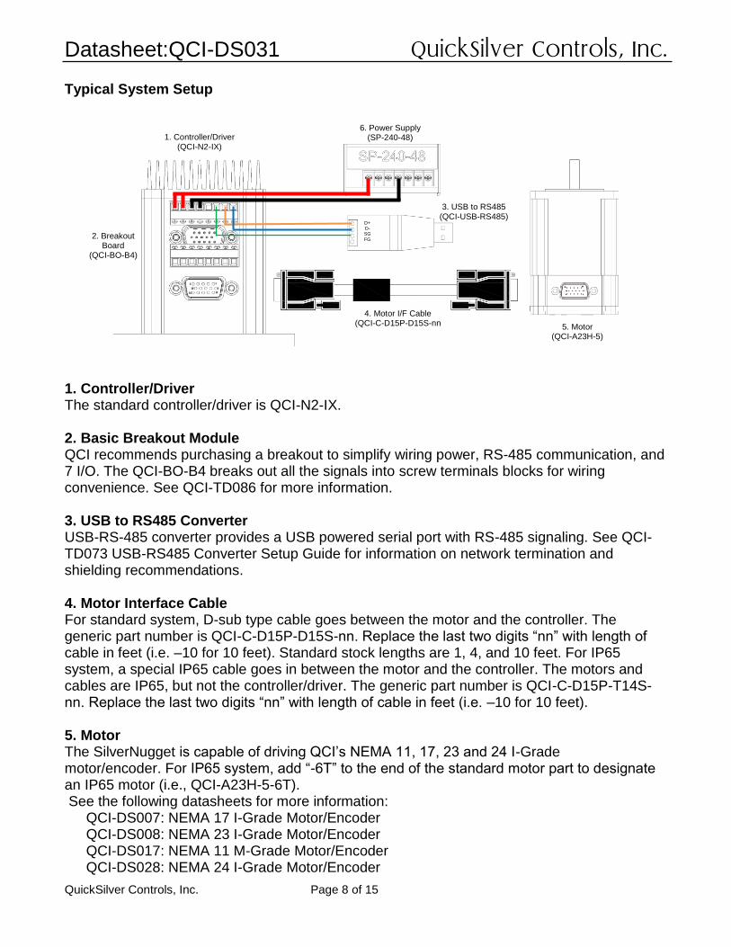
Typical System Setup
1. Controller/Driver The standard controller/driver is QCI-N2-IX. 2. Basic Breakout Module QCI recommends purchasing a breakout to simplify wiring power, RS-485 communication, and 7 I/O. The QCI-BO-B4 breaks out all the signals into screw terminals blocks for wiring convenience. See QCI-TD086 for more information. 3. USB to RS485 Converter USB-RS-485 converter provides a USB powered serial port with RS-485 signaling. See QCI-TD073 USB-RS485 Converter Setup Guide for information on network termination and shielding recommendations. 4. Motor Interface Cable For standard system, D-sub type cable goes between the motor and the controller. The generic part number is QCI-C-D15P-D15S-nn. Replace the last two digits “nn” with length of cable in feet (i.e. –10 for 10 feet). Standard stock lengths are 1, 4, and 10 feet. For IP65 system, a special IP65 cable goes in between the motor and the controller. The motors and cables are IP65, but not the controller/driver. The generic part number is QCI-C-D15P-T14S-nn. Replace the last two digits “nn” with length of cable in feet (i.e. –10 for 10 feet). 5. Motor The SilverNugget is capable of driving QCI’s NEMA 11, 17, 23 and 24 I-Grade motor/encoder. For IP65 system, add “-6T” to the end of the standard motor part to designate an IP65 motor (i.e., QCI-A23H-5-6T). See the following datasheets for more information:
QCI-DS007: NEMA 17 I-Grade Motor/Encoder QCI-DS008: NEMA 23 I-Grade Motor/Encoder QCI-DS017: NEMA 11 M-Grade Motor/Encoder QCI-DS028: NEMA 24 I-Grade Motor/Encoder
1. Controller/Driver (QCI-N2-IX)
2. Breakout Board
(QCI-BO-B4)
4. Motor I/F Cable (QCI-C-D15P-D15S-nn
3. USB to RS485 (QCI-USB-RS485)
5. Motor (QCI-A23H-5)
6. Power Supply (SP-240-48)
D+ D- SG
FG
Datasheet:QCI-DS031 QuickSilver Controls, Inc.
QuickSilver Controls, Inc. Page 9 of 15
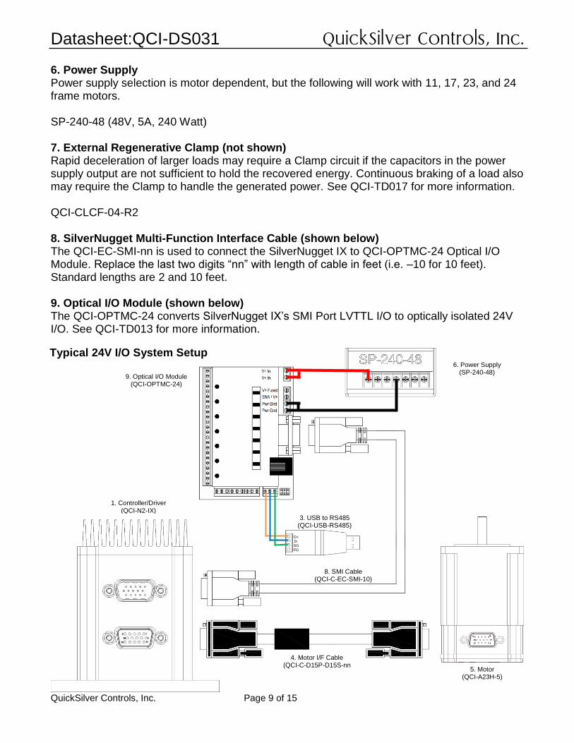
6. Power Supply Power supply selection is motor dependent, but the following will work with 11, 17, 23, and 24 frame motors. SP-240-48 (48V, 5A, 240 Watt) 7. External Regenerative Clamp (not shown) Rapid deceleration of larger loads may require a Clamp circuit if the capacitors in the power supply output are not sufficient to hold the recovered energy. Continuous braking of a load also may require the Clamp to handle the generated power. See QCI-TD017 for more information. QCI-CLCF-04-R2 8. SilverNugget Multi-Function Interface Cable (shown below) The QCI-EC-SMI-nn is used to connect the SilverNugget IX to QCI-OPTMC-24 Optical I/O Module. Replace the last two digits “nn” with length of cable in feet (i.e. –10 for 10 feet). Standard lengths are 2 and 10 feet. 9. Optical I/O Module (shown below) The QCI-OPTMC-24 converts SilverNugget IX’s SMI Port LVTTL I/O to optically isolated 24V I/O. See QCI-TD013 for more information.
D+ D- SG
FG
1. Controller/Driver (QCI-N2-IX)
9. Optical I/O Module (QCI-OPTMC-24)
4. Motor I/F Cable (QCI-C-D15P-D15S-nn
3. USB to RS485 (QCI-USB-RS485)
5. Motor (QCI-A23H-5)
6. Power Supply (SP-240-48)
8. SMI Cable (QCI-C-EC-SMI-10)
Typical 24V I/O System Setup
Datasheet:QCI-DS031 QuickSilver Controls, Inc.
QuickSilver Controls, Inc. Page 10 of 15
New Notable Commands and Features vs. N2-xx-04-EE
Analog Continuous Read Extended (ACX) The ACX command adds additional analog channels that can be read and filtered into a dedicated register. See Command Reference Manual for more information.
Configure I/O (CIO) For the SilverNugget N2-IX series, the CIO commands adds programmable pull-up/pull-down resistors.
Configure I/O, Immediate Mode (CII) The CII command adds the ability to configure an I/O for input or output via serial interface at any time, even during program execution.
Calculation Extended (CLX), Calculation with Data (CLD) Versatile calculation commands with output plus two inputs.
Motor Memory SilverNugget N2-IX has the ability to read motor memory stored in QCI’s I-Grade motors (via Motor Memory signal). Motor memory contains motor type and encoder alignment calibration information. Therefore, running the Index Phase Alignment (IPA) is no longer necessary when initializing the SilverNugget N2-IX nor re-running the IPA when swapping motors, as the SilverNugget N2-IX will automatically read motor memory on power-up. If no motor memory is found or a different motor type was read from what was initialized, the controller will fault and flash the status LED accordingly. See User Manual for status LED information.
Increased Program Buffer Size The SilverNugget N2-IX’s program buffer is 1023 word. For comparison, the SilverNugget N2-xx-04-EE’s program buffer is 200 words.
Multi-Threaded Capability The SilverNugget N2-IX has the capability of running two threads in addition to a motion. If two threads are running, each thread alternates execution, causing each thread to execute at 240 microsecond ticks rather than 120 microsecond ticks when only one thread is running. See Multi-Thread Operation in User Manual for more details.
Datasheet:QCI-DS031 QuickSilver Controls, Inc.
QuickSilver Controls, Inc. Page 11 of 15
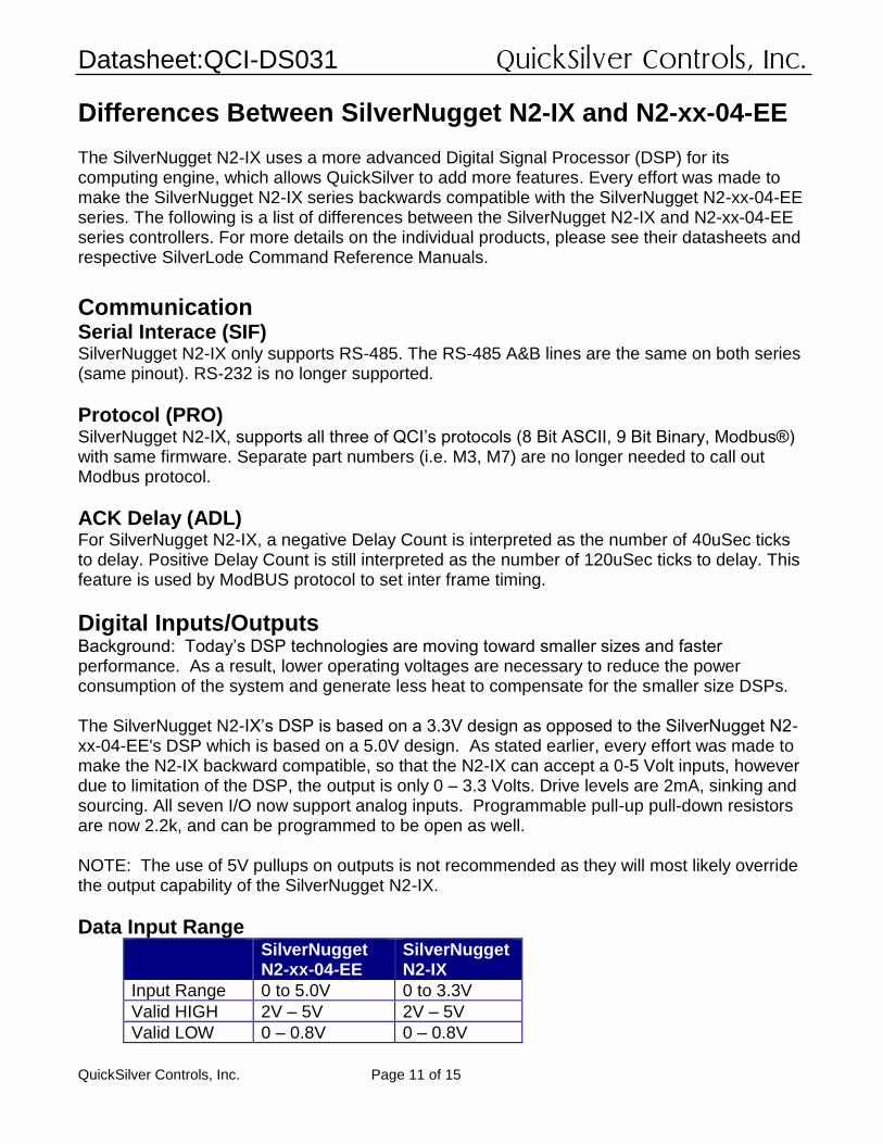
Differences Between SilverNugget N2-IX and N2-xx-04-EE The SilverNugget N2-IX uses a more advanced Digital Signal Processor (DSP) for its computing engine, which allows QuickSilver to add more features. Every effort was made to make the SilverNugget N2-IX series backwards compatible with the SilverNugget N2-xx-04-EE series. The following is a list of differences between the SilverNugget N2-IX and N2-xx-04-EE series controllers. For more details on the individual products, please see their datasheets and respective SilverLode Command Reference Manuals.
Communication Serial Interace (SIF) SilverNugget N2-IX only supports RS-485. The RS-485 A&B lines are the same on both series (same pinout). RS-232 is no longer supported.
Protocol (PRO) SilverNugget N2-IX, supports all three of QCI’s protocols (8 Bit ASCII, 9 Bit Binary, Modbus®) with same firmware. Separate part numbers (i.e. M3, M7) are no longer needed to call out Modbus protocol.
ACK Delay (ADL) For SilverNugget N2-IX, a negative Delay Count is interpreted as the number of 40uSec ticks to delay. Positive Delay Count is still interpreted as the number of 120uSec ticks to delay. This feature is used by ModBUS protocol to set inter frame timing.
Digital Inputs/Outputs Background: Today’s DSP technologies are moving toward smaller sizes and faster performance. As a result, lower operating voltages are necessary to reduce the power consumption of the system and generate less heat to compensate for the smaller size DSPs. The SilverNugget N2-IX’s DSP is based on a 3.3V design as opposed to the SilverNugget N2-xx-04-EE's DSP which is based on a 5.0V design. As stated earlier, every effort was made to make the N2-IX backward compatible, so that the N2-IX can accept a 0-5 Volt inputs, however due to limitation of the DSP, the output is only 0 – 3.3 Volts. Drive levels are 2mA, sinking and sourcing. All seven I/O now support analog inputs. Programmable pull-up pull-down resistors are now 2.2k, and can be programmed to be open as well. NOTE: The use of 5V pullups on outputs is not recommended as they will most likely override the output capability of the SilverNugget N2-IX.
Data Input Range SilverNugget
N2-xx-04-EE SilverNugget N2-IX
Input Range 0 to 5.0V 0 to 3.3V
Valid HIGH 2V – 5V 2V – 5V
Valid LOW 0 – 0.8V 0 – 0.8V
Datasheet:QCI-DS031 QuickSilver Controls, Inc.
QuickSilver Controls, Inc. Page 12 of 15
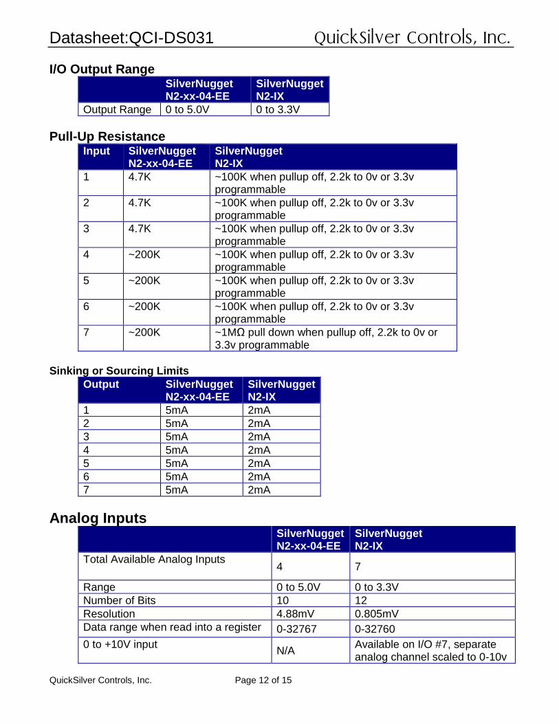
I/O Output Range SilverNugget
N2-xx-04-EE SilverNugget N2-IX
Output Range 0 to 5.0V 0 to 3.3V
Pull-Up Resistance Input SilverNugget
N2-xx-04-EE SilverNugget N2-IX
1 4.7K ~100K when pullup off, 2.2k to 0v or 3.3v programmable
2 4.7K ~100K when pullup off, 2.2k to 0v or 3.3v programmable
3 4.7K ~100K when pullup off, 2.2k to 0v or 3.3v programmable
4 ~200K ~100K when pullup off, 2.2k to 0v or 3.3v programmable
5 ~200K ~100K when pullup off, 2.2k to 0v or 3.3v programmable
6 ~200K ~100K when pullup off, 2.2k to 0v or 3.3v programmable
7 ~200K ~1MΩ pull down when pullup off, 2.2k to 0v or 3.3v programmable
Sinking or Sourcing Limits
Output SilverNugget N2-xx-04-EE
SilverNugget N2-IX
1 5mA 2mA
2 5mA 2mA
3 5mA 2mA
4 5mA 2mA
5 5mA 2mA
6 5mA 2mA
7 5mA 2mA
Analog Inputs SilverNugget
N2-xx-04-EE SilverNugget N2-IX
Total Available Analog Inputs 4 7
Range 0 to 5.0V 0 to 3.3V
Number of Bits 10 12
Resolution 4.88mV 0.805mV
Data range when read into a register 0-32767 0-32760
0 to +10V input N/A
Available on I/O #7, separate analog channel scaled to 0-10v
Datasheet:QCI-DS031 QuickSilver Controls, Inc.
QuickSilver Controls, Inc. Page 13 of 15
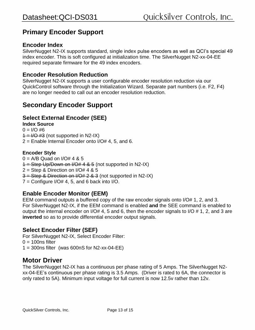
Primary Encoder Support
Encoder Index SilverNugget N2-IX supports standard, single index pulse encoders as well as QCI’s special 49 index encoder. This is soft configured at initialization time. The SilverNugget N2-xx-04-EE required separate firmware for the 49 index encoders.
Encoder Resolution Reduction SilverNugget N2-IX supports a user configurable encoder resolution reduction via our QuickControl software through the Initialization Wizard. Separate part numbers (i.e. F2, F4) are no longer needed to call out an encoder resolution reduction.
Secondary Encoder Support
Select External Encoder (SEE) Index Source 0 = I/O #6 1 = I/O #3 (not supported in N2-IX) 2 = Enable Internal Encoder onto I/O# 4, 5, and 6. Encoder Style 0 = A/B Quad on I/O# 4 & 5 1 = Step Up/Down on I/O# 4 & 5 (not supported in N2-IX) 2 = Step & Direction on I/O# 4 & 5 3 = Step & Direction on I/O# 2 & 3 (not supported in N2-IX) 7 = Configure I/O# 4, 5, and 6 back into I/O.
Enable Encoder Monitor (EEM) EEM command outputs a buffered copy of the raw encoder signals onto I/O# 1, 2, and 3. For SilverNugget N2-IX, if the EEM command is enabled and the SEE command is enabled to output the internal encoder on I/O# 4, 5 and 6, then the encoder signals to I/O # 1, 2, and 3 are inverted so as to provide differential encoder output signals.
Select Encoder Filter (SEF) For SilverNugget N2-IX, Select Encoder Filter: 0 = 100ns filter 1 = 300ns filter (was 600nS for N2-xx-04-EE)
Motor Driver The SilverNugget N2-IX has a continuous per phase rating of 5 Amps. The SilverNugget N2-xx-04-EE’s continuous per phase rating is 3.5 Amps. (Driver is rated to 6A, the connector is only rated to 5A). Minimum input voltage for full current is now 12.5v rather than 12v.
Datasheet:QCI-DS031 QuickSilver Controls, Inc.
QuickSilver Controls, Inc. Page 14 of 15
Commands No Longer Supported The following are commands not supported by SilverNugget N2-IX as the modulo encoder output function is not available in the N2-IX. The new ability to use ratios or high accuracy decimal scaling for the encoder following modes has made the hardware divisors no longer useful.
Modulo Clear (MDC) Modulo Set (MDS) Modulo Trigger (MDT)
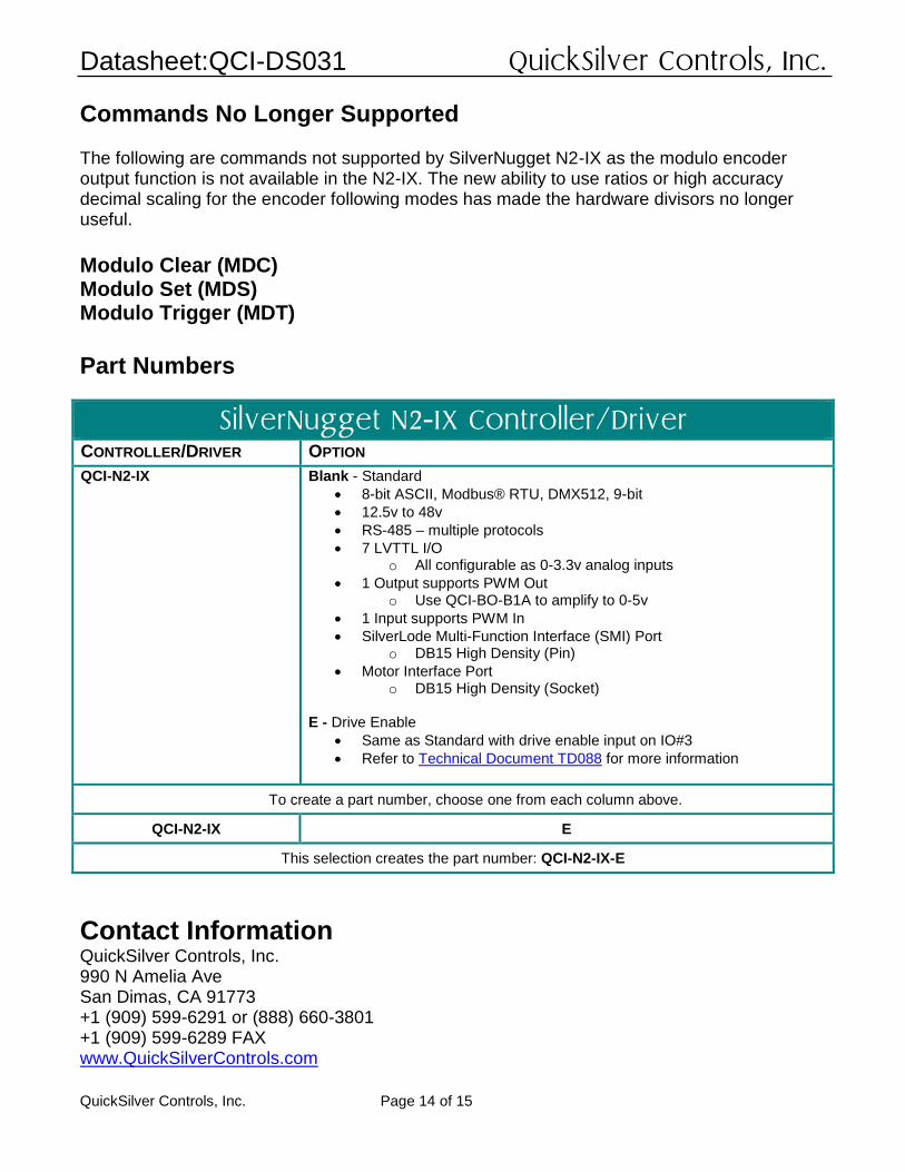
Part Numbers
SilverNugget N2-IX Controller/Driver CONTROLLER/DRIVER OPTION
QCI-N2-IX Blank - Standard
• 8-bit ASCII, Modbus® RTU, DMX512, 9-bit
• 12.5v to 48v
• RS-485 – multiple protocols
• 7 LVTTL I/O o All configurable as 0-3.3v analog inputs
• 1 Output supports PWM Out o Use QCI-BO-B1A to amplify to 0-5v
• 1 Input supports PWM In
• SilverLode Multi-Function Interface (SMI) Port o DB15 High Density (Pin)
• Motor Interface Port o DB15 High Density (Socket)
E - Drive Enable
• Same as Standard with drive enable input on IO#3
• Refer to Technical Document TD088 for more information
To create a part number, choose one from each column above.
QCI-N2-IX E
This selection creates the part number: QCI-N2-IX-E
Contact Information QuickSilver Controls, Inc. 990 N Amelia Ave San Dimas, CA 91773 +1 (909) 599-6291 or (888) 660-3801 +1 (909) 599-6289 FAX www.QuickSilverControls.com
Datasheet:QCI-DS031 QuickSilver Controls, Inc.
QuickSilver Controls, Inc. Page 15 of 15


![Scanned by CamScannerprepadda.com/.../upsc17/UPSC...hindi-Question-Paper[].pdf38. à 39. (qci)' 1. qci 2. qci 40. (sfbs) (d) 1,23$r3 amc-u-bklp (apmchud)', 1. apmchud 2006 §3.tt,](https://img.pdfslide.us/doc/110x75/5b1aec137f8b9a2d258e0f6e/scanned-by-pdf38-a-39-qci-1-qci-2-qci-40-sfbs-d-123r3-amc-u-bklp.jpg)