Embed Size (px)
Citation preview

P011.02Dual channel low cost gate driver board for PrimePACKTM IGBT module
Revision: 5; Date: 06.05.2015
© 2011-2015 ANVILEX GmbH All right reserved. Page 1
General description
This device is a ready to use low cost compact dual-channel
advanced gate driver board, designed to control wide range of high
power medium-voltage PrimePACKTM 2 and PrimePACKTM 3 IGBT
modules of various manufacturers with rated collector-emitter volt-
age of 1700V and rated collector current up to 1400A. The gate
driver board is suitable for chopper, two- and multi-level and many
others known applications. The gate driver board features a fiber
optic interface. Advanced control and protection functions are
included and allow the design of high reliability systems. Balancing
technology of positive and negative gate supply voltages allows
reliable switching behaviors over under wide range of loads. Free
access to the fastening screws of the IGBT module base plate
allows checking fastening torques without removal of the gate
driver board.
Applications
• General purpose low-/medium-voltage inverters
• Multilevel inverters
• Resonant converters
• Wind power generation
• Solar power generation
• Industrial AC and DC motor drives
• Uninterruptible power supplies (UPS)
• Switched-mode power supplies (SMPS)
• Power factor correctors (PFC)
• Active filters (AF)
• Induction heating and welding
• Radiology and laser technology
• Research
• Traction
• Railroad power supplies
• Galvanic and electroplating
• Static Synchronous Compensator (STATCOM)
Features
• Ready to use gate driver board for PrimePACKTM IGBT module
• Suitable for PrimePACKTM 2 and PrimePACKTM 3 IGBT module
• Suitable for chopper, two- and multi-level inverter topologies
• Small form factor
• Direct mounting onto IGBT module
• High reliability, long life
• No electrolytic capacitors used
• Wide range supply voltage 18…28 VDC
• No stabilized supply voltage required
• Opposite supply voltage polarity protection
• Two independent isolated DC/DC converters
• Monitoring of supply voltage
• Fiber optic links for control and fault status signals
• Switching frequency from DC to 10 kHz
• Duty cycle from 0% to 100%
• Gate peak current up to 35 A
• Monitoring of gate voltage at on-state
• Positive and negative gate voltage balancing
• IGBT module short-circuit protection
• Active Miller clamp feature
• Active gate pull-down if no supply voltage present
• Passive VCE clamping at turn-off
• Optional two steps turn-off with adjustable level and delay
• Reliable desaturation detection at low VCE voltage
• Fault status output
• UVLO protection
• Safe isolation according EN 50178

P011.02Dual channel low cost gate driver board for PrimePACKTM IGBT module
Revision: 5; Date: 06.05.2015
© 2011-2015 ANVILEX GmbH All right reserved. Page 2
Important notice
Please read these instructions for use carefully and keep them for later use, be sure to make them accessible to other users and observe infor-
mation they contain.
Trademarks and brands
PrimePACKTM is a trade mark of Infineon Technologies AG, Munich, Germany.
SEMITRANS® is a registered trade mark of SEMIKRON International GmbH, Nuremberg, Germany.
All other named trademarks or/and brands are the property of their respective owners.
Caution and safety warnings
• Handling all high-voltage equipment involves risk of live.
• Any handling of IGBT module and gate driver board is subject to the general specification for protecting electrostatic sensitive devices accord-
ing to international standard IEC 60747-1, Chapter IX or European standard EN 100015. If these specifications are not followed, both IGBT
module and gate driver board may be damaged.
• Pay attention to clearance and creepage distances between parts with different voltage potentials (e.g. busbar, heatsink, mechanical suspen-
sion etc.).
• Pay attention to fastening torques and insertion/retention forces, polarity of gate driver supply voltage, polarity of power terminals.
• Dirtiness and/or mechanical damages (e.g. oxidation, scratches, delaminating of coating) on gate driver board and IGBT module may dramati-
cally decrease isolation properties of it and may cause permanent damage of the gate driver board and IGBT module.
• To avoid pollution of fiber optic connectors protective rubber plugs must be removed directly before insertion of fiber optic cables.
• Never remove protective rubber plugs of fiber optic connectors, connect/disconnect fiber optic cables on both gate driver board and control
equipment until supply voltage of gate driver board applied.
• Never connect or disconnect power supply connector until supply voltage applied on it. This handling may cause permanent damage of the
gate driver board.
• Avoid permanent damage of the gate driver board, personal and equipment injury, never remove protective rubber plugs of fiber optic connec-
tors, connect or disconnect fiber optic cables at both gate driver board and control equipment sides, connect or disconnect power supply con-
nector of the gate driver board until voltage across collector and emitter of IGBT module applied.
• Application of gate driver board with improper IGBT module may cause permanent damage to the gate driver board and/or IGBT module.
• Application of gate driver board with damaged or defected IGBT module may cause permanent damage of the gate driver board or affect gate
driver board reliability.
• Save fiber optic cables from damaging by sharp corners, heat parts, etc., pay attention on bending radius. Damaged fiber optic cable can
cause malfunction or/and damage or permanent lost of equipment and human life.
• HFBR-1521Z LED transmitters are classified as IEC 60825-1 Accessible Emission Limit (AEL) Class 1 based upon the current proposed draft
scheduled to go into effect on 1st January 1997. AEL Class 1 LED devices are considered eye safe.
Absolute maximum ratings
Stresses beyond those listed under “Absolute maximum ratings” may cause permanent damage to the gate driver board. These are stress rat-
ings only, functional operation of the gate driver board under these or any other conditions beyond those indicated in the operational sections of
the specification are not implied. Exposure to absolute maximum rating conditions for extended periods may affect gate driver board reliability.
Table 1. Absolute maximum ratings.
Parameter Symbol Conditions Min. Typ. Max. Units
Input supply voltage VCC Applied to 24V and 0V power supply termi-nals.
-30 - +30 V
Collector-emitter voltage VCE Applied to CT and ET/CB, ET/CB and EB terminals.
- - 1463 V
P011.02Dual channel low cost gate driver board for PrimePACKTM IGBT module
Revision: 5; Date: 06.05.2015
© 2011-2015 ANVILEX GmbH All right reserved. Page 3
Parameter Symbol Conditions Min. Typ. Max. Units
Gate-emitter voltage VGE Applied to GT und ET/CB, GB and EB termi-nals.
-17 - 17 V
Gate peak current IG - - 40 A
Switching frequency fSW Output power must not exceed maximal al-lowed output power.
- - 15 kHz
Output power PG Output power per channel. - - 5 W
Isolation test voltage VISO(Pri/Sec) Applied between primary to secondary side terminals, 50 Hz, 1 min, According EN 50178.
- - 4000 V
Operating peak voltage VOP(Pri/Sec) Applied to primary and secondary side termi-nals.
- - 1700 V
Operating ambient temperature TA 0 - 65 °C
Storage ambient temperature TS -40 - 90 °C
Recommended operations conditions
Table 2. Recommended operations conditions.
Parameter Symbol Conditions Min. Typ. Max. Units
Input supply voltage VCC Applied to 24V and 0V power supply termi-nals.
18 24(1) 28 V
Collector-emitter voltage VCE Applied to CT and ET/CB, ET/CB and EB terminals.
- - 1200 V
Switching frequency fSW Output power must not exceed maximal al-lowed output power.
0 - 10 kHz
Output power PG Output power per channel. - - 4 W
Duty cycle D 0 - 100 %
Operating ambient temperature TA 0 - 55 °C
Note 1. To increase withstand to possible disturbances of supply voltage (e.g. voltage dips, oscillations, interferences) we recommend to use
24V supply voltage as supply voltage for gate driver board.
Insulation characteristics
Table 3. Insulation characteristics.
Parameter Symbol Conditions Min. Typ. Max. Units
Pollution degree - According to DIN VDE 0110, 1/89. 2 -
Maximum working isolation voltage VIORM Applied between primary and secondary side terminals.
2000 - - V
Highest allowable over voltage VIOTM Applied between primary and secondary side terminals.
4000 - - V
Insulation and safety related specification
Table 4. Insulation and safety related specification.
Parameter Symbol Conditions Min. Typ. Max. Units
Isolation testing voltage VISO(PRI/SEC) Applied between primary and secondary side terminals, 50 Hz, 1 min, According EN 50178.
4000 - - V
Input-Output coupling capacitance CISO(PRI/SEC) f = 1 MHz, measured between power supply terminal X1 and output terminals CT, GT, ET/CB, GB, EB. Total capacitance given for both channels.
- 6.6 - pF
P011.02Dual channel low cost gate driver board for PrimePACKTM IGBT module
Revision: 5; Date: 06.05.2015
© 2011-2015 ANVILEX GmbH All right reserved. Page 4
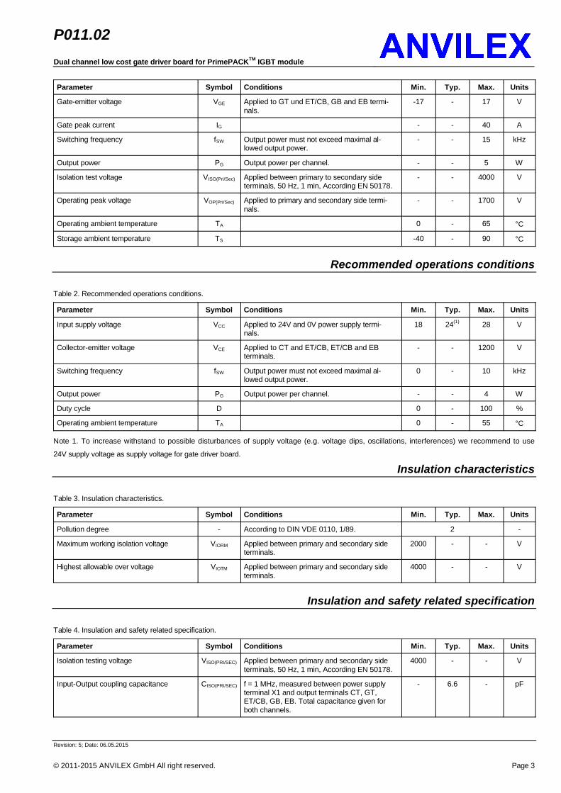
Parameter Symbol Conditions Min. Typ. Max. Units
Input-Output coupling resistance RISO(PRI/SEC) 400 - - MΩ
Partial discharge extinction voltage VE 50 Hz, QPD ≤ 10 pQ, According to IEC 60272. 2000 - - V
Minimum external air gap (clearance) between primary and secondary side
dA(PRI/SEC) Shortest distance through air measured be-tween primary potential island to secondary potential island. According to IEC 60664-1 and EC 50124-1.
19.10 - - mm
Minimum external tracking (creepage) between primary and secondary side
dS(PRI/SEC) Shortest path along body and surface meas-ured from primary potential island to secon-dary potential island. According to IEC 60664-1 and EC 50124-1.
19.10 - - mm
Minimum internal insulation gap (internal clearance) primary and secondary side
dI(PRI/SEC) Through insulation distance conductor to conductor, usually the straight line distance thickness between the primary and secondary windings of isolation transformer.
0.93 - - mm
Minimum external air gap (clearance) between secondary sides
dA(SEC/SEC) Shortest distance through air measured from top to bottom secondary side. According to IEC 60664-1 and EC 50124-1.
7.30 - - mm
Minimum external tracking (creepage) between secondary sides
dS(SEC/SEC) Shortest path along body and surface meas-ured from input terminals to output terminals, shortest distance path along body. According to IEC 60664-1 and EC 50124-1.
18.60 - - mm
Tracking resistance(Comparative tracking index)
CTI DIN IEC 112 / VDE 0303 Part 1. 175 - 400 V
Isolation material group - According to DIN VDE 0110, 1/89 Table 1. IIIa -
Electrical specifications (DC)
Unless otherwise noted, all typical values at VCC = 24 V DC, TA = 25 °C. All minimum/maximum values are at conditions listed under “Recom-
mended operating conditions”.
Table 5. Electrical DC specification.
Parameter Symbol Conditions Min. Typ. Max. Units
Input supply voltage VCC Applied to 24V and 0V supply input terminals. 18 24 28 V
Quiescent supply current ICC No load connected to gate output, off-state. - 160 - mA
Startup supply voltage VCC(START) Full functionality not guaranteed until VCC out of specified range 18V…28V.
- - 16.0 V
Supply voltage under voltage lockout VCC(UVLO) 15.5 - - V
Startup time tSTART - 10 50 ms
Steady on-state, no switching. 15.0 15.3 15.6 VGate-Emitter voltage at on-state VGE(ON)
fSW = 10 kHz, PG = 4 W 14.5 15.0 - V
Steady off-state no switching. -7.5 -7.8 -8.1 VGate-Emitter voltage at off-state VGE(OFF)
fSW = 10 kHz, PG = 4 W -7.0 -7.5 - V
Desaturation threshold voltage VCE(DESAT) - 7.5 - V
VUVLO(LO) - 10 - VGate-Emitter under voltage threshold
VUVLO(HI) - 11 - V
Active Miller clamp voltage VCLAMP - 2.0 - V
Gate pull-down voltage VPULL_DOWN No power supply voltage present or under specified startup level.
- 3.0 - V
High level output current IOH - - 35 A
Low level output current IOL - - 35 A
Maximum output power PG Output power per channel. 4 - - W
P011.02Dual channel low cost gate driver board for PrimePACKTM IGBT module
Revision: 5; Date: 06.05.2015
© 2011-2015 ANVILEX GmbH All right reserved. Page 5
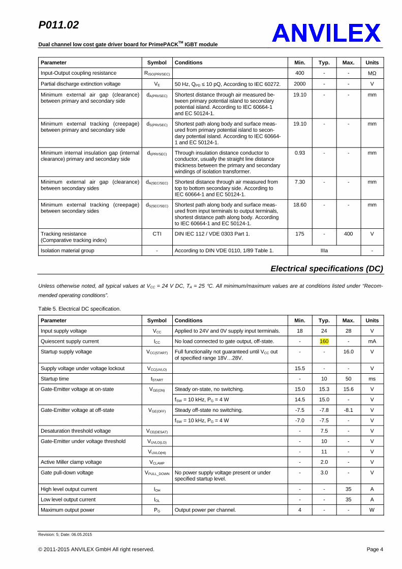
Switching specifications (AC)
Unless otherwise noted, all typical values at VCC = 24 V DC, TA = 25 °C. All minimum/maximum values are at conditions listed under “Recom-
mended operating conditions”.
Table 6. Switching AC specification.
Parameter Symbol Conditions Min. Typ. Max. Units
Switching frequency fSW PG < 4 W - - 10(1) kHz
Duty cycle D 0 - 100 %
tCTRL(ON) 240 - - nsMinimal control signal width
tCTRL(OFF) 180 - - ns
Propagation delay time at turn-on tP(ON) - 580 - ns
Propagation delay time at turn off tP(OFF) - 530 - ns
Dead time between channels tDT - 0(2) - ns
Desaturation sense time tDESAT - 7270(3) - ns
Desaturation sense time to error signal delay
tDESAT(FB) - 7000 - ns
Gate-Emitter under voltage sense time tUV - TBD - ns
Gate-Emitter under voltage sense to feedback signal delay
tUV(FB) - 140 - ns
Output high level common mode tran-sient immunity
|CMH| 75 - - kV/µs
Output low level common mode transient immunity
|CML| 75 - - kV/µs
Note 1. The maximum switching frequency depends on the IGBT gate charge.
Note 2. Dead time insertion not implemented.
Note 3. Desaturation time can be adjusted on request.
Optical interface specifications
Unless otherwise noted, all typical values at TA = 25 °C.
Table 7. Optical interface specification.
Parameter Symbol Conditions Min. Typ. Max. Units
Standard fiber optic cable. - - 15 mFeedback signal transmit distance L
Improved fiber optic cable. - - - m
Fiber optic receiver - Control signal fiber optic connector. HFBR-2521Z -
Fiber optic transmitter - Feedback signal fiber optic connector. HFBR-1521Z -
Mechanical specifications
Unless otherwise noted, all typical values at TA = 25 °C.
Table 8. Mechanical specification.
Parameter Symbol Conditions Min. Typ. Max. Units
Dimensions - L × W × H, Typical, see outline drawing. 160.0 × 89.0 × 14.5(1), (2) mm
Weight m - 65 - g
Single wire. 0.2 - 4.0 mm2Allowable cross section of power supply wire
SPOWER
Stranded wire. 0.2 - 2.5 mm2
P011.02Dual channel low cost gate driver board for PrimePACKTM IGBT module
Revision: 5; Date: 06.05.2015
© 2011-2015 ANVILEX GmbH All right reserved. Page 6
Parameter Symbol Conditions Min. Typ. Max. Units
Mounting torques of IGBT module termi-nals
MIGBT IGBT module terminals, M4 screw. 1.0(3) - 3.0(3) Nm
Fiber optic connector insertion force FI - 8 30 N
Fiber optic connectors retention force FR 7 8 - N
Note 1. Maximal components height (measured from bottom side of printed circuit board) on the top side of driver board 10.0 mm.
Note 2. Maximal components height (measured from bottom side of printed circuit board) on the bottom side of driver board 4.5 mm.
Note 3. Given fastening torques related to the gate driver board. Consult IGBT module datasheet to determinate minimum and maximum
required mounting torques.
Timing diagrams
VCE(SAT)
Light on
Active Miller clamp
VGE
ControlLight off
Light on
Light offFault
Inactive
Active
VCE
VDC
VGH
VGL
tPD(OFF)tPD(ON)
tCTRL(ON)
VGE(CLAMP)
VGE(TH)
tCTRL(OFF)
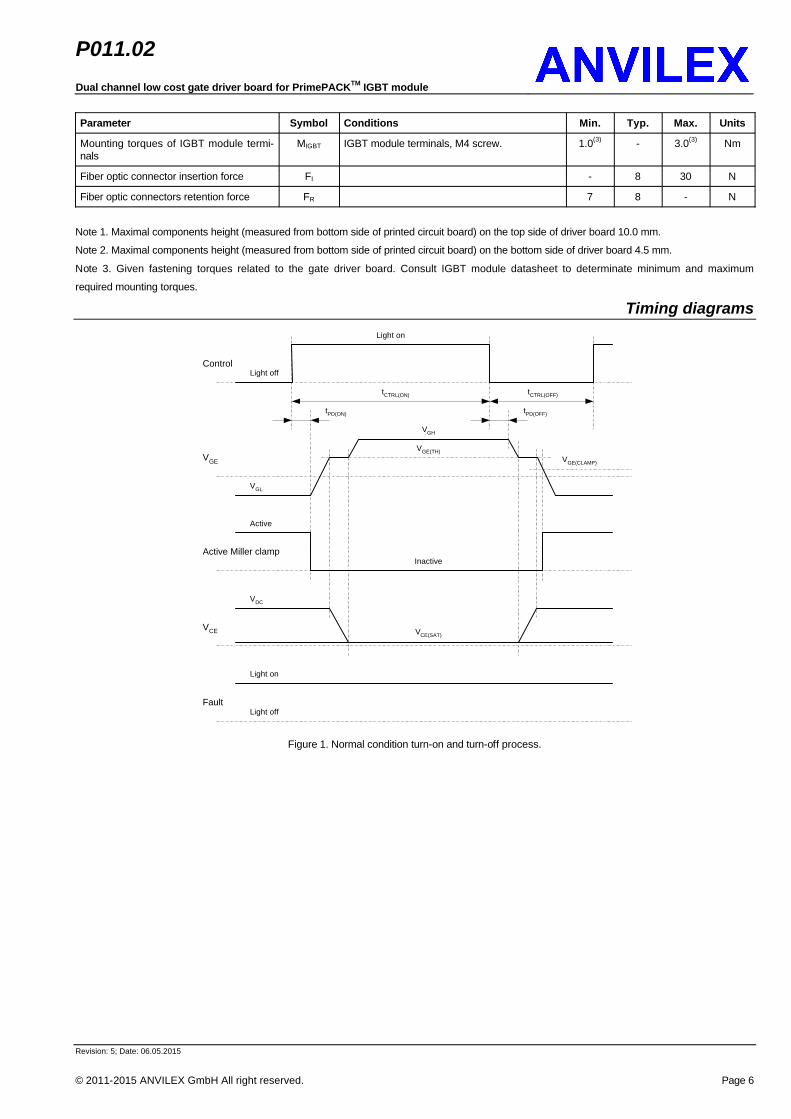
Figure 1. Normal condition turn-on and turn-off process.
P011.02Dual channel low cost gate driver board for PrimePACKTM IGBT module
Revision: 5; Date: 06.05.2015
© 2011-2015 ANVILEX GmbH All right reserved. Page 7
VCE(DESAT)
Light on
Active Miller clamp
VGE
ControlLight off
Light on
Light offFault
Inactive
Active
VCE
VDC
VGH
VGL
tPD(ON)
tCTRL(ON)
tPD(ON)
tPD(DESAT)
tPD(FS) tPD(FR)
VGE(CLAMP)
tCTRL(OFF)
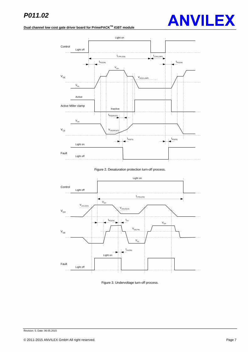
Figure 2. Desaturation protection turn-off process.
Light on
VGE
ControlLight off
Light on
Light offFault
VGH
VGH
VGL
tPD(ON)
tCTRL(ON)
VGH
VUVLO(LO)
VUVLO(HI)
VGE(TH)
tUV
tUV(FB)
Figure 3. Undervoltage turn-off process.

P011.02Dual channel low cost gate driver board for PrimePACKTM IGBT module
Revision: 5; Date: 06.05.2015
© 2011-2015 ANVILEX GmbH All right reserved. Page 8
Detailed descriptionThe device is ready to use low cost compact dual-channel advanced gate driver board. They are designed to control wide range of high power
medium-voltage PrimePACKTM 2 and PrimePACKTM 3 IGBT module of various manufacturers with rated collector-emitter voltage of 1700V and
rated collector current up to 1400A. The gate driver board suitable for chopper, two- and multi-level and many others known applications. The
gate driver board features a fiber optic interface. Advanced control and protection functions are included and allow the design of high reliability
systems. Special developed balancing technology of positive and negative gate supply voltages allows reliable switching behaviors over under
wide range of loads. Free access to the fastening screws of IGBT module base plate allows checking fastening torques without removal of the
gate driver board.
The gate driver board receives control signal via fiber optical connectors mounted in the middle of the gate driver board. The input is triggered
by the edge of control optic signal. Connected to the gate driver board is IGBT going on, when input control optic signal (light) present. The input
control signal pulse width TCTRL(ON) must be larger than the minimal pulse width, shorter control signals are ignored. Input signals longer than
minimal pulse width are transmitted to the gate of IGBT module after the delay TPD(ON) with minimum width distortion. This timing also valid for
the input control signal width TCTRL(OFF). To prevent partial turn-on and/or partial turn-off of IGBT short input control signals should be avoided
and not generated by control equipment. The minimal width of the input control signals differ by the used IGBT module and application and
should be experimentally estimated in each application case.
The gate driver board does not insert any dead time delays to the input control signal. Dead time delays insertion must be provided by customer
control equipment to prevent possible cross conduction condition of IGBT module. The gate driver board also don’t monitor activation of both
input control signals at some time. Typical turn-on and turn-off processes are shown on the Figure 1.
The output stage of gate driver board is able to sink and source current of 40A over the full temperature range. Separated turn-on and turn-off
gate resistors as well as active miller clamp resistor allow independent gate charge and discharge control. By default, recommended by IGBT
module manufacturer values of the turn-on and turn-off resistors recalculated to +15.0V/-7.5V gate voltages are used. All available product con-
figurations are listed in the section “Ordering information”. To meet application and EMC requirements turn-on and turn-off gate resistors can be
adjusted on request. Gate driver boards also available without mounted gate resistors to allow application specific adjustments.
Optional two level turn-off is used to increase application reliability during overcurrent state. During turn-off, gate voltage can be reduced to a
programmed level and time in the order to reduce the IGBT current (in event of overcurrent). This action avoids both dangerous overvoltage
across the IGBT, and RBSOA problems, especially at short circuit turn-off. By default two level turn-off disabled, please contact us if this option
required.
Innovative active Miller clamp function allows the control of the Miller current during a high dV/dt situation and prevents unexpected turn-on of
IGBT. During turn-off, the gate voltage is monitored and the clamp output is activated when gate voltage goes below 2V relative emitter poten-
tial. The clamp function is disabled when the input light signal goes active again.
Desaturation protection ensures the protection of IGBT in the event of overcurrent. When the collector-emitter voltage goes higher desaturation
threshold, after a blanking time the output of the gate driver board is driven low and the fault status output is activated. By enabled 2-level turn-
off feature 2-level turn-off process is used. The fault state is exited at the next rising edge of control input signal. Depending on used IGBT mod-
ule and application desaturation threshold and blanking time can be adjusted on request.
Undervoltage detection (UVLO) protects the IGBT in the event of a insufficient positive gate supply voltage (during startup and fault situation).
During undervoltage, the output of the gate driver board is active pull-down until positive gate supply voltage remains higher than 2V. Passive
pull-down is used for the positive gate supply voltage below 2V. Fault status output signal the undervoltage state and is reset only when under-
voltage state disappears. Typical undervoltage turn-off process is shown on Figure 3.
Fault status outputs of the gate driver board are used to signal fault condition (desaturation, UVLO) to a control equipment. Fault condition is
signaled via fiber optical connectors mounted in the middle of the gate driver board. Reactions of the fault status signal on the different faults
conditions are shown on the Figure 1, Figure 2 and Figure 3.
Active gate pull-down feature prevents unexpected turn-on of IGBT if no power supply of the gate driver boards present. Then VGE voltage reach
level around 3V the active gate pull-down circuit going active and pull-down gate of IGBT.
P011.02Dual channel low cost gate driver board for PrimePACKTM IGBT module
Revision: 5; Date: 06.05.2015
© 2011-2015 ANVILEX GmbH All right reserved. Page 9
Electrical configuration
DC+
AC
CT
GT
ET/CB
DC-
GB
EB
IGBT ModuleGate Driver Board
DC Power Supply
Customer Control Unit
Fiber Optic Link
Fiber Optic Link
Fiber Optic Link
Fiber Optic Link
CTF
FTF
CBF
FBF
CT
GT
ET/CB
GB
EBTwisted Wire Connection X1:24V
X1:0V
CTF
FTF
CBF
FBF
24V
0V
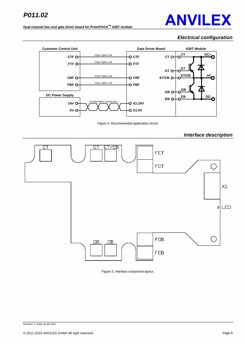
Figure 4. Recommended application circuit.
Interface description
Figure 5. Interface component layout.
P011.02Dual channel low cost gate driver board for PrimePACKTM IGBT module
Revision: 5; Date: 06.05.2015
© 2011-2015 ANVILEX GmbH All right reserved. Page 10
Table 9. Interface description.
Designation Media type Function
Power supply
X1:24V electric Supply input 24V DC
X1:0V electric 0V DC
Control and feedback status signals
CFT fiber optic Optical control signal input of the top IGBT
FFT fiber optic Optical fault status signal output of the top IGBT
CFB fiber optic Optical control signal input of the bottom IGBT
FFB fiber optic Optical fault status signal output of the bottom IGBT
IGBT signals
CT electric Collector signal of the top IGBT
GT electric Gate signal of the top IGBT
ET/CB electric Emitter signal of the top IGBT / Collector signal of the bottom IGBT
GB electric Gate signal of the bottom IGBT
EB electric Emitter signal of the bottom IGBT
Mechanical dimensions
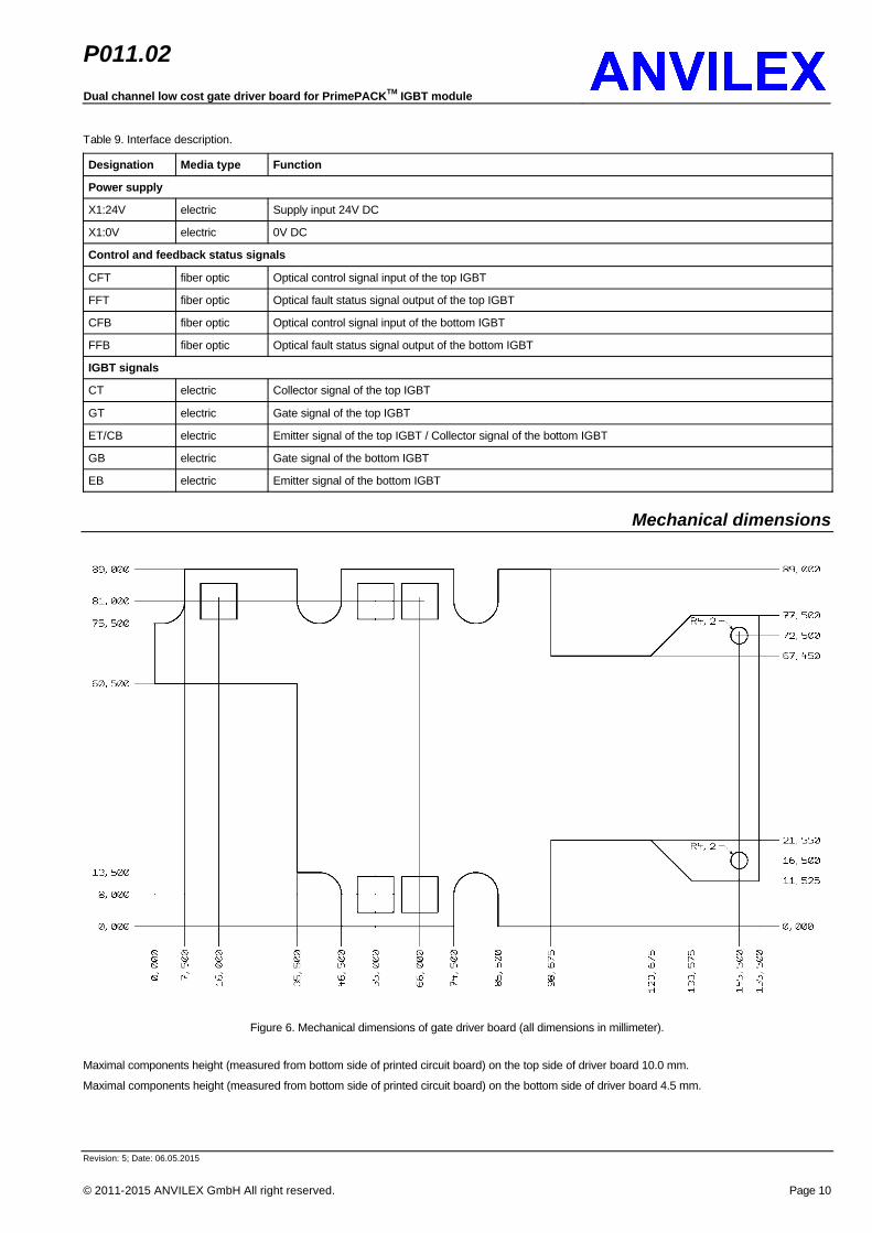
Figure 6. Mechanical dimensions of gate driver board (all dimensions in millimeter).
Maximal components height (measured from bottom side of printed circuit board) on the top side of driver board 10.0 mm.
Maximal components height (measured from bottom side of printed circuit board) on the bottom side of driver board 4.5 mm.
P011.02Dual channel low cost gate driver board for PrimePACKTM IGBT module
Revision: 5; Date: 06.05.2015
© 2011-2015 ANVILEX GmbH All right reserved. Page 11
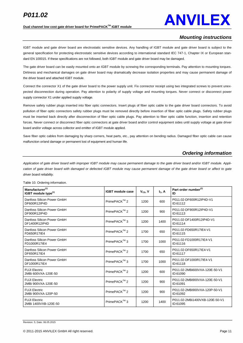
Mounting instructions
IGBT module and gate driver board are electrostatic sensitive devices. Any handling of IGBT module and gate driver board is subject to the
general specification for protecting electrostatic sensitive devices according to international standard IEC 747-1, Chapter IX or European stan-
dard EN 100015. If these specifications are not followed, both IGBT module and gate driver board may be damaged.
The gate driver board can be easily mounted onto an IGBT module by screwing the corresponding terminals. Pay attention to mounting torques.
Dirtiness and mechanical damages on gate driver board may dramatically decrease isolation properties and may cause permanent damage of
the driver board and attached IGBT module.
Connect the connector X1 of the gate driver board to the power supply unit. Fix connector receipt using two integrated screws to prevent unex-
pected disconnection during operation. Pay attention to polarity of supply voltage and mounting torques. Never connect or disconnect power
supply connector X1 under applied supply voltage.
Remove safety rubber plugs inserted into fiber optic connectors. Insert plugs of fiber optic cable to the gate driver board connectors. To avoid
pollution of fiber optic connectors safety rubber plugs must be removed directly before insertion of fiber optic cable plugs. Safety rubber plugs
must be inserted back directly after disconnection of fiber optic cable plugs. Pay attention to fiber optic cable function, insertion and retention
forces. Never connect or disconnect fiber optic connectors at gate driver board and/or control equipment sides until supply voltage at gate driver
board and/or voltage across collector and emitter of IGBT module applied.
Save fiber optic cables from damaging by sharp corners, heat parts, etc., pay attention on bending radius. Damaged fiber optic cable can cause
malfunction or/and damage or permanent lost of equipment and human life.
Ordering information
Application of gate driver board with improper IGBT module may cause permanent damage to the gate driver board and/or IGBT module. Appli-
cation of gate driver board with damaged or defected IGBT module may cause permanent damage of the gate driver board or affect to gate
driver board reliability.
Table 10. Ordering information.
Manufacturer(1)
IGBT module type(1) IGBT module case VCE, V IC, A Part order number(2)
ID
Danfoss Silicon Power GmbHDF600R12IP4D PrimePACKTM 2 1200 600 P011.02-DF600R12IP4D-V1
ID:61112
Danfoss Silicon Power GmbHDF900R12IP4D PrimePACKTM 2 1200 900 P011.02-DF900R12IP4D-V1
ID:61113
Danfoss Silicon Power GmbHDF1400R12IP4D PrimePACKTM 3 1200 1400 P011.02-DF1400R12IP4D-V1
ID:61114
Danfoss Silicon Power GmbHFD650R17IE4 PrimePACKTM 2 1700 650 P011.02-FD650R17IE4-V1
ID:61115
Danfoss Silicon Power GmbHFD1000R17IE4 PrimePACKTM 3 1700 1000 P011.02-FD1000R17IE4-V1
ID:61116
Danfoss Silicon Power GmbHDF650R17IE4 PrimePACKTM 2 1700 650 P011.02-DF650R17IE4-V1
ID:61117
Danfoss Silicon Power GmbHDF1000R17IE4 PrimePACKTM 3 1700 1000 P011.02-DF1000R17IE4-V1
ID:61118
FUJI Electric2MBi 600VXA-120E-50 PrimePACKTM 2 1200 600 P011.02-2MBi600VXA-120E-50-V1
ID:61090
FUJI Electric2MBi 900VXA-120E-50 PrimePACKTM 2 1200 900 P011.02-2MBi900VXA-120E-50-V1
ID:61091
FUJI Electric2MBi 900VXA-120P-50 PrimePACKTM 2 1200 900 P011.02-2MBi900VXA-120P-50-V1
ID:61092
FUJI Electric2MBi 1400VXB-120E-50 PrimePACKTM 3 1200 1400 P011.02-2MBi1400VXB-120E-50-V1
ID:61095

P011.02Dual channel low cost gate driver board for PrimePACKTM IGBT module
Revision: 5; Date: 06.05.2015
© 2011-2015 ANVILEX GmbH All right reserved. Page 12
Manufacturer(1)
IGBT module type(1) IGBT module case VCE, V IC, A Part order number(2)
ID
FUJI Electric2MBi 1400VXB-120P-50 PrimePACKTM 3 1200 1400 P011.02-2MBi1400VXB-120P-50-V1
ID:61096
FUJI Electric1MBi 900VXA-120PD PrimePACKTM 2 1200 900 P011.02-1MBi 900VXA-120PD-50-V1
ID:61104
FUJI Electric1MBi 900VXA-120PC PrimePACKTM 2 1200 900 P011.02-1MBi900VXA-120PC-50-V1
ID:61105
FUJI Electric1MBi 1200VXB-120PL PrimePACKTM 3 1200 1200 P011.02-1MBi1200VXB-120PL-50-V1
ID:61108
FUJI Electric1MBi 1200VXB-120PH PrimePACKTM 3 1200 1200 P011.02-1MBi1200VXB-120PH-50-V1
ID:61109
FUJI Electric2MBi 650VXA-170E-50 PrimePACKTM 2 1700 650 P011.02-2MBi650VXA-170E-50-V1
ID:61093
FUJI Electric2MBi 650VXA-170EA-50 PrimePACKTM 2 1700 650 P011.02-2MBi650VXA-170EA-50-V1
ID:61094
FUJI Electric1MBi 650VXA-170EL-50 PrimePACKTM 2 1700 650 P011.02-1MBi650VXA-170EL-50-V1
ID:61102
FUJI Electric1MBi 650VXA-170EH-50 PrimePACKTM 2 1700 650 P011.02-1MBi650VXA-170EH-50-V1
ID:61103
FUJI Electric2MBi 1000VXB-170E-50 PrimePACKTM 3 1700 1000 P011.02-2MBi1000VXB-170E-50-V1
ID:61097
FUJI Electric2MBi 1000VXB-170EA-50 PrimePACKTM 3 1700 1000 P011.02-2MBi1000VXB-170EA-50-V1
ID:61098
FUJI Electric2MBi 1000VXB-170P-50 PrimePACKTM 3 1700 1000 P011.02-2MBi1000VXB-170P-50-V1
ID:61099
FUJI Electric1MBi 1000VXB-170EL-50 PrimePACKTM 3 1700 1000 P011.02-1MBi1000VXB-170EL-50-V1
ID:61106
FUJI Electric1MBi 1000VXB-170EH-50 PrimePACKTM 3 1700 1000 P011.02-1MBi1000VXB-170EH-50-V1
ID:61107
FUJI Electric2MBi 1000VXB-170E-50 PrimePACKTM 3 1700 1000 P011.02-2MBi1000VXB-170E-50-V1
ID:61097
FUJI Electric2MBi 1400VXB-170E-50 PrimePACKTM 3 1700 1400 P011.02-2MBi1400VXB-170E-50-V1
ID:61100
FUJI Electric2MBi 1400VXB-170P-50 PrimePACKTM 3 1700 1400 P011.02-2MBi1400VXB-170P-50-V1
ID:61101
FUJI Electric2MBi 1400VXB-170EL-50 PrimePACKTM 3 1700 1400 P011.02-2MBi1400VXB-170EL-50-V1
ID:61110
FUJI Electric2MBi 1400VXB-170EH-50 PrimePACKTM 3 1700 1400 P011.02-2MBi1400VXB-170EH-50-V1
ID:61111
Infineon AGFF450R12IE4 PrimePACKTM 2 1200 450 P011.02-FF450R12IE4-V1
ID:61401
Infineon AGFF600R12IE4 PrimePACKTM 2 1200 600 P011.02-FF600R12IE4-V1
ID:61402
Infineon AGFF600R12IP4 PrimePACKTM 2 1200 600 P011.02-FF600R12IP4-V1
ID:61403
Infineon AGFF600R12IS4F PrimePACKTM 2 1200 600 P011.02-FF600R12IS4F-V1
ID:61404
Infineon AGFF900R12IE4 PrimePACKTM 2 1200 900 P011.02-FF900R12IE4-V1
ID:61405
Infineon AGFF900R12IP4 PrimePACKTM 2 1200 900 P011.02-FF900R12IP4-V1
ID:61406
Infineon AGFF900R12IP4D PrimePACKTM 2 1200 600 P011.02-FF900R12IP4D-V1
ID:61407

P011.02Dual channel low cost gate driver board for PrimePACKTM IGBT module
Revision: 5; Date: 06.05.2015
© 2011-2015 ANVILEX GmbH All right reserved. Page 13
Manufacturer(1)
IGBT module type(1) IGBT module case VCE, V IC, A Part order number(2)
ID
Infineon AGFF1400R12IP4 PrimePACKTM 3 1200 1400 P011.02-FF1400R12IP4-V1
ID:61408
Infineon AGFD600R12IP4D PrimePACKTM 2 1200 600 P011.02-FD600R12IP4D-V1
ID:61409
Infineon AGFD900R12IP4D PrimePACKTM 2 1200 900 P011.02-FD900R12IP4D-V1
ID:61410
Infineon AGFD1400R12IP4 PrimePACKTM 3 1200 600 P011.02-FD1400R12IP4-V1
ID:61411
Infineon AGFF450R17IE4 PrimePACKTM 2 1700 450 P011.02-FF450R17IE4-V1
ID:491
Infineon AGFF650R17IE4 PrimePACKTM 2 1700 650 P011.02-FF650R17IE4-V1
ID:28446
Infineon AGFF650R17IE4D_B2 PrimePACKTM 2 1700 650 P011.02-FF650R17IE4D_B2-V1
ID:28496
Infineon AGFF1000R17IE4 PrimePACKTM 3 1700 1000 P011.02-FF1000R17IE4-V1
ID:28608
Infineon AGFF1000R17IE4D_B2 PrimePACKTM 3 1700 1000 P011.02-FF1000R17IE4D_B2-V1
ID:28609
Infineon AGFF1400R17IP4 PrimePACKTM 2 1700 1400 P011.02-FF1400R17IP4-V1
ID:28610
IXYS GmbHMIXA 1400PF1200TSP SimBus P 1200 1400 P011.02-MIXA1400PF1200TSP-V1
ID:62746
IXYS GmbHMIXA 1400PF1700TSP SimBus P 1700 1400 P011.02-MIXA1400PF1700TSP-V1
ID:62747
SEMIKRON International GmbHSKM1000GB17S2 SEMITRANS® 10 1700 1000 P011.02-SKM1000GB17S2-V1
ID: TBD
SEMIKRON International GmbHSKM1400GB17S2 SEMITRANS® 10 1700 1400 P011.02-SKM1400GB17S2-V1
ID: TBD
SEMIKRON International GmbHSKM1000GAL17S2 SEMITRANS® 10 1700 1000 P011.02-SKM1000GAL17S2-V1
ID: TBD
SEMIKRON International GmbHSKM1400GAL17S2 SEMITRANS® 10 1700 1400 P011.02-SKM1400GAL17S2-V1
ID: TBD
SEMIKRON International GmbHSKM1000GAR17S2 SEMITRANS® 10 1700 1000 P011.02-SKM1000GAR17S2-V1
ID: TBD
SEMIKRON International GmbHSKM1400GAR17S2 SEMITRANS® 10 1700 1400 P011.02-SKM1400GAR17S2-V1
ID: TBD
StarpowerGD450HFL120P1S PrimePACKTM 2 1200 450 P011.02-GD450HFL120P1S-V1
ID:28549
StarpowerGD600HFL120P1S PrimePACKTM 2 1200 600 P011.02-GD600HFL120P1S-V1
ID:28601
StarpowerGD900HFL120P1S PrimePACKTM 2 1200 900 P011.02-GD900HFL120P1S-V1
ID:28605
StarpowerGD1400HFL120P2S PrimePACKTM 3 1200 1400 P011.02-GD1400HFL120P2S-V1
ID:28547
StarpowerGD450HFT120P1S PrimePACKTM 2 1200 450 P011.02-GD450HFT120P1S-V1
ID:28550
StarpowerGD600HFT120P1S PrimePACKTM 2 1200 600 P011.02-GD600HFT120P1S-V1
ID:28603
StarpowerGD900HFT120P1S PrimePACKTM 2 1200 900 P011.02-GD900HFT120P1S-V1
ID:28606
StarpowerGD1400HFT120P2S PrimePACKTM 3 1200 1400 P011.02-GD1400HFT120P2S-V1
ID:28548

P011.02Dual channel low cost gate driver board for PrimePACKTM IGBT module
Revision: 5; Date: 06.05.2015
© 2011-2015 ANVILEX GmbH All right reserved. Page 14
Manufacturer(1)
IGBT module type(1) IGBT module case VCE, V IC, A Part order number(2)
ID
StarpowerGD450HFL170P1S PrimePACKTM 2 1700 450 P011.02-GD450HFL170P1S-V1
ID:28607
StarpowerGD600HFL170P1S PrimePACKTM 2 1700 600 P011.02-GD600HFL170P1S-V1
ID:28602
StarpowerGD1000HFL120P2S PrimePACKTM 3 1700 1000 P011.02-GD1000HFL120P2S-V1
ID:26451
StarpowerGD450HFT170P1S PrimePACKTM 2 1700 450 P011.02-GD450HFT170P1S-V1
ID:28600
StarpowerGD600HFT170P1S PrimePACKTM 2 1700 600 P011.02-GD600HFT170P1S-V1
ID:28604
StarpowerGD1000HFT120P2S PrimePACKTM 3 1700 1000 P011.02-GD1000HFT120P2S-V1
ID:61088
Xi'an Yongdian Electric Co., Ltd.YMIBH1000-17 PrimePACKTM 3 1700 1000 P011.02-YMIBH1000-17-V1
ID:61089
Note 1. If IGBT module manufacturer or IGBT module missing in ordering information table, please contact ANVILEX Technologies UG for more
information.
Note 2. By default gate driver boards equipped with gate resistors recommended by manufacturer of IGBT module. If differ values of gate resis-
tors required, please contact ANVILEX Technologies UG for customer specific version of gate driver board. To order gate driver board without
gate resistors please use order code: P011.02-BASIC.
Disposal
Please dispose product in accordance with the directive 2002/96/EG – WEEE (Waste Electrical and Electronic Equipment). If you have any
question, please refer to the local authorities responsible for waste disposal.
Terms and conditions of usage
The data contained in this product data sheet is exclusively intended for technically trained staff. Handling all high-voltage equipment involves
risk of live. You and your technical departments will have to evaluate the suitability of the product for the intended application and the complete-
ness of the product data with respect to such application.
All HFBR-1521Z LED transmitters are classified as IEC 825-1 Accessible Emission Limit (AEL) Class 1 based upon the current proposed draft
scheduled to go into effect on 1st January 1997. AEL Class 1 LED devices are considered eye safe. For more information contact the ANVILEX
GmbH directly or the sales office which is responsible for you.
This product data sheet describes the characteristics of this product for which a warranty is granted. Any such warranty is granted exclusively
pursuant the terms and conditions of the supply agreement. There will be no guarantee of any kind for the product and its characteristics.
Should you require additional product information to the data given in this product data sheet or which concerns the specific application of our
product, please contact the ANVILEX GmbH. Directly or the sales office, which is responsible for you. For those that are specifically interested
application notes are provided.
Due to technical requirements our product may contain dangerous substances. For information on the substances in question please contact
the ANVILEX GmbH directly or the sales office, which is responsible for you.
Should you intend to use the product in health or life endangering or life support applications, please notify.
ANVILEX GmbH reserves the right to make any technical modification of product and/or change this product data sheet without notice at any
time in the course of product improvement.
P011.02Dual channel low cost gate driver board for PrimePACKTM IGBT module
Revision: 5; Date: 06.05.2015
© 2011-2015 ANVILEX GmbH All right reserved. Page 15
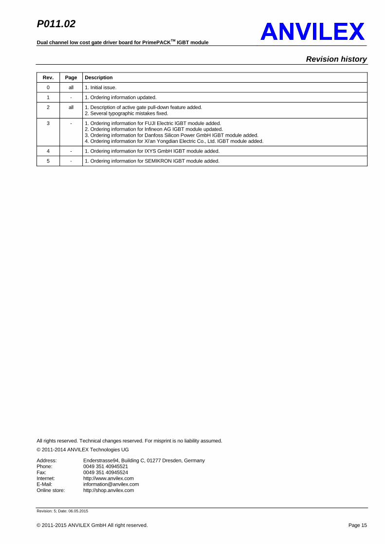
Revision history
Rev. Page Description
0 all 1. Initial issue.
1 - 1. Ordering information updated.
2 all 1. Description of active gate pull-down feature added.2. Several typographic mistakes fixed.
3 - 1. Ordering information for FUJI Electric IGBT module added.2. Ordering information for Infineon AG IGBT module updated.3. Ordering information for Danfoss Silicon Power GmbH IGBT module added.4. Ordering information for Xi'an Yongdian Electric Co., Ltd. IGBT module added.
4 - 1. Ordering information for IXYS GmbH IGBT module added.
5 - 1. Ordering information for SEMIKRON IGBT module added.
All rights reserved. Technical changes reserved. For misprint is no liability assumed.
© 2011-2014 ANVILEX Technologies UG
Address: Enderstrasse94, Building C, 01277 Dresden, GermanyPhone: 0049 351 40945521Fax: 0049 351 40945524Internet: http://www.anvilex.comE-Mail: [email protected] store: http://shop.anvilex.com


![DRAFT MALAYSIAN STANDARD - · PDF file4 Principles and practical application of the MS IEC 60664 series for insulation dimensioning of LV equipment ... [IEC 60664-1:2007, 3.20]](https://img.pdfslide.us/doc/110x75/5aa5ab9c7f8b9a2f048db7d6/draft-malaysian-standard-4-principles-and-practical-application-of-the-ms-iec.jpg)