Embed Size (px)
Citation preview
DataSheetDIN Rail Mount
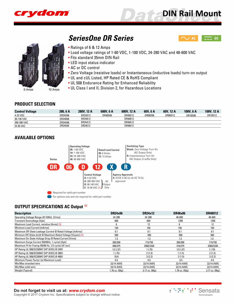
SeriesOne DR Series• Ratings of 6 & 12 Amps• Load voltage ratings of 1-60 VDC, 1-100 VDC, 24-280 VAC and 48-600 VAC• Fits standard 35mm DIN Rail• LED input status indicator• AC or DC control• Zero Voltage (resistive loads) or Instantaneous (inductive loads) turn-on output• UL and cUL Listed, HP Rated CE & RoHS Compliant• UL 508 Endurance Rating for Enhanced Reliability• UL Class I and II, Division 2, for Hazardous Locations
PRODUCT SELECTIONControl Voltage 280, 6 A 280V, 12 A 600V, 6 A 600V, 12 A 60V, 6 A 60V, 12 A 100V, 6 A 100V, 12 A4-32 VDC DR24D06 DR10D1290-140 VAC DR24B06200-280 VAC DR24A06
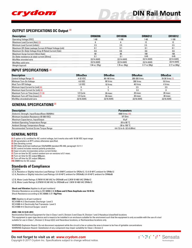
AVAILABLE OPTIONS
OUTPUT SPECIFICATIONS AC Output (2)
Description DR24x06 DR24x12 DR48x06 DR48X12Operating Voltage Range (47-63Hz) [Vrms] 24-280 24-280 48-600 48-600Transient Overvoltage [Vpk] 600 600 1200 1200Maximum Load Current, resistive [Arms] (3) 6 12 6 12
150 150 150 1500.1 0.1 0.1 0.1
Minimum Load Current [mArms]
500 500 500 500
Maximum Surge Current (50/60Hz, 1 cycle) [Apk]1.3 1.3 1.3 1.3Maximum On-State Voltage Drop @ Rated Current [Vrms]
285/300 715/750 285/300 715/750400/375 2560/2330 410/375 2560/2330Maximum I²t for Fusing (50/60 Hz, 1/2 cycle) [A² sec]1/2 (.37) 1 (.75) 1/2 (.37) 1 (.75)1 (.75) 2 (1.5) 1 (1.5) 2 (1.5)
18-36 VAC
DR24D12DR24B12DR24A12
DR48D06DR48B12
DR48E12DR48A12
DR48D12 DR06D06 DR06D12 DR10D06
DR24E06 DR24E12
ACOutputOnly
Series
Operating Voltage06: 1-60 VDC10: 1-100 VDC24: 24-280 VAC48: 48-600 VAC
Rated Load Current06: 6 Amps12: 12 Amps
Control VoltageD: 4-32 VDCA: 200-265 VACB: 90-140 VACE: 18-36 VAC (1)
1206 DDR XAgency ApprovalsX: ATEX II 3G Ex nA IIC T4 Gc approved
Switching TypeBlank: Zero Voltage Turn-On (AC Output Only)R: Instantaneous Turn-On (AC Output, D suffix Only)
R
Required for valid part numberFor options only and not required for valid part number
Maximum Off-State Leakage Current @ Rated Voltage [mArms]Minimum Off-State dv/dt @ Maximum Rated Voltage [V/µsec] (4)
HP Rating UL 508/IEC60947 [HP (KW)] @ 240V
Minimum Power Factor (at Maximum Load)Min/Max stranded wire
HP Rating UL 508/IEC60947 [HP (KW)] @ 380VHP Rating UL 508/IEC60947 [HP (KW)] @ 480V
Min/Max solid wireWeight (Typical)
N/A 2 (1.5)3 (2.2) 3 (2.2)0.5 0.5 0.5 0.5
22/14 AWG 22/14 AWG 22/14 AWG 22/14 AWG22/14 AWG22/14 AWG 22/14 AWG 22/14 AWG
1.76 oz. (50g) 1.76 oz. (50g)3.17 oz. (90g) 3.17 oz. (90g)
Do not forget to visit us at: www.crydom.comCopyright © 2017 Crydom Inc. Specifications subject to change without notice.
DCAC
DataSheetDIN Rail Mount
Do not forget to visit us at: www.crydom.comCopyright © 2017 Crydom Inc. Specifications subject to change without notice.
INPUT SPECIFICATIONS (2)
DRxxExxDRxxBxxDRxxDxxDescriptionControl Voltage Range (5) 4-32 VDC 200-265 Vrms 18-36 Vrms (1)Minimum Turn-On Voltage 4.0 VDC 200 Vrms 18 VrmsMust Turn-Off Voltage 1.0 VDC 40 Vrms 4 VrmsMinimum Input Current for [mA] (6) 9 2.5 3.5Maximum Input Current for [mA] (6) 11 3.3 8
1/2 Cycle 20 msec 20 msecMaximum Turn-on Time [msec] (7) (8)1/2 Cycle 30 msec 30 msecMaximum Turn-off Time [msec] (9)
22/16 AWG 22/16 AWG 22/16 AWG
GENERAL SPECIFICATIONS (2)
Description ParametersDielectric Strength, Input/Output/Base (50/60Hz) 4000 Vrms (10) Minimum Insulation Resistance (@ 500 VDC)Maximum Capacitance, Input/Output 10 pFAmbient Operating Temperature Range -30 to 80 °CAmbient Storage Temperature Range -30 to 100 °CRecommended Terminal Screw Torque Range
109 Ohm
OUTPUT SPECIFICATIONS DC Output (2)
Description DR06D06 DR10D06 DR06D12 DR10D12Operating Voltage [VDC] 1-60 1-100 1-60 1-100Maximum Load Current [Adc] (3) 6 6 12 12Minimum Load Current [mAdc] 2.5 2.5 2.5 2.5
0.1 0.1 0.1 0.10.6 0.6 0.6 0.6
Maximum Off-State Leakage Current @ Rated Voltage [mA]Maximum On-State Voltage Drop @ Rated Current [Vpk]
60 60On-State resistance at rated current [Ohms] 0.1 0.1Min/Max stranded wire 22/14 AWG 22/14 AWG
22/14 AWG 22/14 AWG1.94 oz. (55g) 1.76 oz. (50g)
Min/Max solid wireWeight (typical)
Maximum Surge Current (10ms) [Apk] 100 1000.45
22/14 AWG22/14 AWG3.17 oz (90g)
0.45
22/14 AWG3.17 oz.(90g)
22/14 AWG
Min/Max stranded/solid wire
DRxxAxx90-140 Vrms
90 Vrms10 Vrms
35
20 msec30 msec
22/16 AWG
GENERAL NOTES
(2) All parameters at 25°C unless otherwise specified. (1) E option is UL certified for AC control voltage, but it works also with 18-36 VDC input range.
(3) See Derating curves (4) Off-State dv/dt test method per EIA/NARM standard RS-443, paragraph 13.11.1 (5) DC control includes reverse polarity protection.(6) Input circuitry incorporates active current limiter.(7) Turn-on time for DC control random turn-on versions is 0.1 msec.(8) Turn-on time for DC output 600µsec.(9) Turn-off time for DC output 300µsec.(10) 2500Vrms for DC output.
LC A, Resistive or Slightly Inductive Load Ratings: 12 A @40°C ambient for DR24x12, 12 A @ 40°C ambient for DR48x12LC A, Resistive or Slightly Inductive Load Ratings: 6 A @ 40°C ambient for DR24x06, 6 A @ 40°C ambient for DR48x06
LC B, Motor Loads Ratings: 0.75KW @ 240 VAC for DR24x06 and 2.2KW @ 480 VAC DR48x12LC B, Motor Loads Ratings: 0.375KW @ 240 VAC for DR24x06 and 1.5KW @ 480 VAC DR48x12
Standards of Compliance
IEC 62314
Shock and Vibration (Applies to all part numbers)Vibration Resistence according to IEC 60068-2-6: 0.35mm and 0.75mm Amplitude over 10-55 HzShock Resistance according to IEC 60068-2-27: 15g/11ms
EMC (Applies to all part numbers)IEC 61000-4-2: Electrostatic Discharge- Level 3IEC 61000-4-4: Electrically Fast Transients- Level 3IEC 61000-4-5: Electrical Surges- Level 3
ANSI / ISA 12.12.01-2013Nonincendive Electrical Equipment for Use in Class I and II, Division 2 and Class III, Division 1 and 2 Hazadous (classified) locationsThis equipment is open-type device and is meant to be installed in an enclosure suitable for the enviroment such that the equipment is only accesible with the use of a toolsuitable for use in Class 1, Division 2, Group A,B,C and Hazardous locations, or Nonhazardous locations only
WARNING-Explosion Hazard- Do not disconnect equipment while the circuit is live or unless the area is known to be free of ignitable concentrationsWARNING-Explosion Hazard- Substitution of any component may impair suitability for Class I, Division 2
4.4-7.0 in-lb (0.5-0.8Nm)
DataSheetDIN Rail Mount
Do not forget to visit us at: www.crydom.comCopyright © 2017 Crydom Inc. Specifications subject to change without notice.
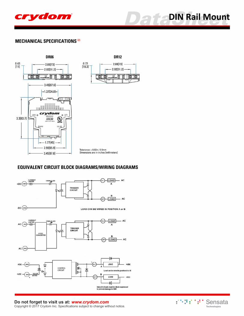
MECHANICAL SPECIFICATIONS (2)
EQUIVALENT CIRCUIT BLOCK DIAGRAMS/WIRING DIAGRAMS
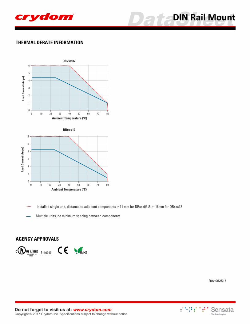
Installed single unit, distance to adjacent components ≥ 11 mm for DRxxx06 & ≥ 18mm for DRxxx12
DataSheetDIN Rail Mount
Do not forget to visit us at: www.crydom.comCopyright © 2017 Crydom Inc. Specifications subject to change without notice.
Rev 052516
6
5
4
3
2
1
100 20 30 40 50 60 70 800
Ambient Temperature (ºC)
Load
Cur
rent
(Am
ps)
DRxxx06
12
10
8
6
4
2
100 20 30 40 50 60 70 800
Ambient Temperature (ºC)
Load
Cur
rent
(Am
ps)
DRxxx12
Installed single unit, distance to adjacent components ≥ 11 mm for DRxxx06 & ≥ 18mm for DRxxx12
Multiple units, no minimum spacing between components
AGENCY APPROVALS
THERMAL DERATE INFORMATION
E116949 IND. CONT. EQ.
4WB8
DataSheetDIN Rail Mount
Do not forget to visit us at: www.crydom.comCopyright © 2017 Crydom Inc. Specifications subject to change without notice.
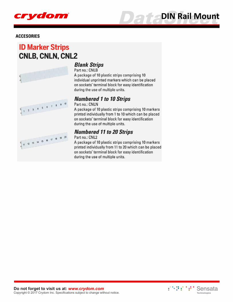
ACCESORIES
DataSheetDIN Rail Mount
Do not forget to visit us at: www.crydom.comCopyright © 2017 Crydom Inc. Specifications subject to change without notice.
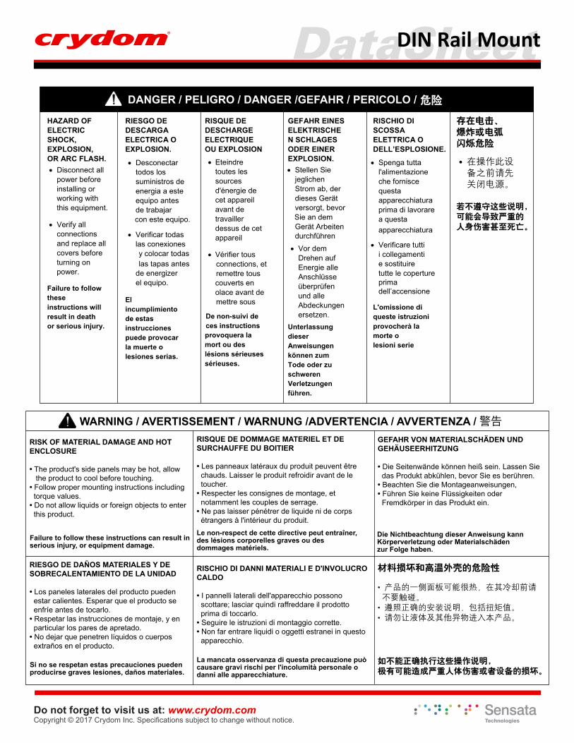
DANGER / PELIGRO / DANGER /GEFAHR / PERICOLO / 危险
HAZARD OF ELECTRIC SHOCK, EXPLOSION, OR ARC FLASH. • Disconnect all
power before installing or working with this equipment.
• Verify all connections and replace all covers before turning on power.
Failure to follow these instructions will result in death or serious injury.
RIESGO DE DESCARGA ELECTRICA O EXPLOSION.
• Desconectar todos los suministros de energia a este equipo antes de trabajar con este equipo.
• Verificar todas las conexiones y colocar todas las tapas antes
de energizer el equipo.
El incumplimiento de estas instrucciones puede provocar la muerte o lesiones serias.
RISQUE DE DESCHARGE ELECTRIQUE OU EXPLOSION • Eteindre
toutes les sources d'énergie de cet appareil avant de travailler dessus de cet appareil
• Vérifier tousconnections, etremettre tous couverts enolace avant demettre sous
De non-suivi de ces instructions provoquera la mort ou des lésions sérieuses sérieuses.
GEFAHR EINES ELEKTRISCHEN SCHLAGES ODER EINER EXPLOSION.• Stellen Sie
jeglichen Strom ab, der dieses Gerät versorgt, bevor
Sie an dem Gerät Arbeiten durchführen
• Vor dem Drehen auf Energie alle Anschlüsse überprüfen und alle Abdeckungen ersetzen.
Unterlassung dieser Anweisungen können zum Tode oder zu schwerenVerletzungen führen.
RISCHIO DI SCOSSA ELETTRICA O DELL’ESPLOSIONE.
• Spenga tutta l'alimentazioneche fornisce questa apparecchiaturaprima di lavorarea questa apparecchiatura
• Verificare tutti i collegamenti e sostituire tutte le coperture prima dell’accensione
L'omissione di queste istruzioni provocherà la morte olesioni serie
存在电击、爆炸或电弧闪烁危险
• 在操作此设备之前请先关闭电源。
若不遵守这些说明,可能会导致严重的人身伤害甚至死亡。
WARNING / AVERTISSEMENT / WARNUNG /ADVERTENCIA / AVVERTENZA / 警告
RISK OF MATERIAL DAMAGE AND HOT ENCLOSURE
• The product's side panels may be hot, allow the product to cool before touching.• Follow proper mounting instructions including torque values.• Do not allow liquids or foreign objects to enter this product.
Failure to follow these instructions can result in serious injury, or equipment damage.
RISQUE DE DOMMAGE MATERIEL ET DE SURCHAUFFE DU BOITIER
• Les panneaux latéraux du produit peuvent être chauds. Laisser le produit refroidir avant de le toucher.• Respecter les consignes de montage, et notamment les couples de serrage. • Ne pas laisser pénétrer de liquide ni de corps étrangers à l'intérieur du produit.Le non-respect de cette directive peut entraîner,des lésions corporelles graves ou des dommages matériels.
Die Nichtbeachtung dieser Anweisung kannKörperverletzung oder Materialschäden zur Folge haben.
GEFAHR VON MATERIALSCHÄDEN UND GEHÄUSEERHITZUNG
• Die Seitenwände können heiß sein. Lassen Sie das Produkt abkühlen, bevor Sie es berühren.• Beachten Sie die Montageanweisungen, • Führen Sie keine Flüssigkeiten oder Fremdkörper in das Produkt ein.
Si no se respetan estas precauciones pueden producirse graves lesiones, daños materiales.
RIESGO DE DAÑOS MATERIALES Y DE SOBRECALENTAMIENTO DE LA UNIDAD
• Los paneles laterales del producto pueden estar calientes. Esperar que el producto se enfríe antes de tocarlo.• Respetar las instrucciones de montaje, y en particular los pares de apretado.• No dejar que penetren líquidos o cuerpos extraños en el producto.
La mancata osservanza di questa precauzione può causare gravi rischi per l'incolumità personale o danni alle apparecchiature.
RISCHIO DI DANNI MATERIALI E D'INVOLUCRO CALDO
• I pannelli laterali dell'apparecchio possono scottare; lasciar quindi raffreddare il prodotto prima di toccarlo.• Seguire le istruzioni di montaggio corrette.• Non far entrare liquidi o oggetti estranei in questo apparecchio.
如不能正确执行这些操作说明,极有可能造成严重人体伤害或者设备的损坏。
材料损坏和高温外壳的危险性
• 产品的一侧面板可能很热,在其冷却前请 不要触碰。• 遵照正确的安装说明,包括扭矩值。• 请勿让液体及其他异物进入本产品。
DataSheetDIN Rail Mount
Do not forget to visit us at: www.crydom.comCopyright © 2017 Crydom Inc. Specifications subject to change without notice.
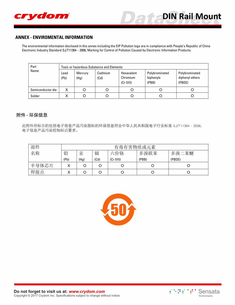
ANNEX - ENVIROMENTAL INFORMATION
The environmental information disclosed in this annex including the EIP Pollution logo are in compliance with People’s Republic of China Electronic Industry Standard SJ/T11364 – 2006, Marking for Control of Pollution Caused by Electronic Information Products.
PartName
Toxic or hazardous Substance and Elements
Lead Mercury Cadmium Hexavalent Polybrominated Polybrominated(Pb) (Hg) (Cd) Chromium
(Cr (VI)) biphenyls(PBB)
diphenyl ethers (PBDE)
Semiconductor die
Solder
附件 - 环保信息
此附件所标示的包括电子信息产品污染图标的环保信息符合中华人民共和国电子行业标准 SJ/T11364 - 2006,电子信息产品污染控制标识要求。
有毒有害物质或元素件部
名称 铅 汞 镉 六价铬 多溴联苯 多溴二苯醚 (Pb) (Hg) (Cd) (Cr (VI)) (PBB) (PBDE)
半导体芯片
焊接点
50