Embed Size (px)
Citation preview
1-29www.phdinc.com/cv • (800) 624-8511
CV
PHDV1
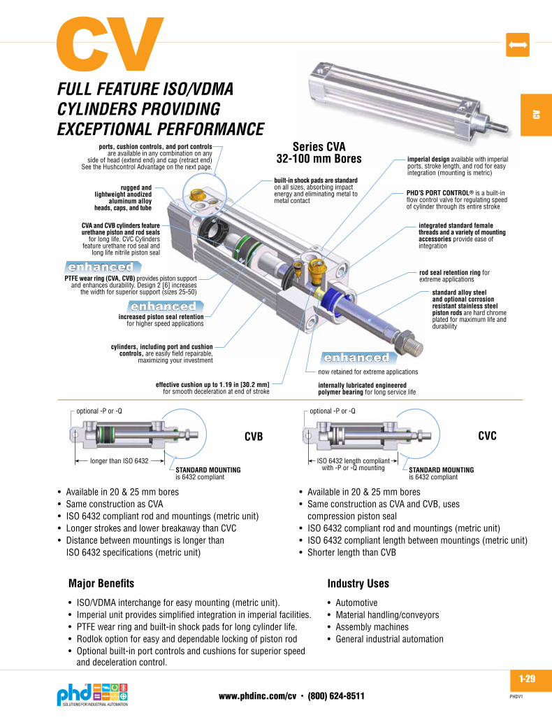
ports, cushion controls, and port controlsare available in any combination on any
side of head (extend end) and cap (retract end)See the Hushcontrol Advantage on the next page.
now retained for extreme applications
internally lubricated engineeredpolymer bearing for long service life
effective cushion up to 1.19 in [30.2 mm]for smooth deceleration at end of stroke
standard alloy steeland optional corrosionresistant stainless steelpiston rods are hard chromeplated for maximum life anddurability
integrated standard femalethreads and a variety of mountingaccessories provide ease ofintegration
built-in shock pads are standardon all sizes, absorbing impactenergy and eliminating metal tometal contact
PHD’S PORT CONTROL® is a built-inflow control valve for regulating speedof cylinder through its entire stroke
PTFE wear ring (CVA, CVB) provides piston supportand enhances durability. Design 2 [6] increases
the width for superior support (sizes 25-50)
CVA and CVB cylinders featureurethane piston and rod seals
for long life. CVC Cylindersfeature urethane rod seal and
long life nitrile piston seal
rugged andlightweight anodized
aluminum alloyheads, caps, and tube
cylinders, including port and cushioncontrols, are easily field repairable,
maximizing your investment
Series CVA32-100 mm Bores
increased piston seal retentionfor higher speed applications
rod seal retention ring forextreme applications
imperial design available with imperialports, stroke length, and rod for easyintegration (mounting is metric)
enhanced
enhanced
enhanced
Major Benefits
• ISO/VDMAinterchangeforeasymounting(metricunit).• Imperialunitprovidessimplifiedintegrationinimperialfacilities.• PTFEwearringandbuilt-inshockpadsforlongcylinderlife.• Rodlokoptionforeasyanddependablelockingofpistonrod• Optionalbuilt-inportcontrolsandcushionsforsuperiorspeed anddecelerationcontrol.
Industry Uses
• Automotive• Materialhandling/conveyors• Assemblymachines• Generalindustrialautomation
• Availablein20&25mmbores• SameconstructionasCVA• ISO6432compliantrodandmountings(metricunit)• LongerstrokesandlowerbreakawaythanCVC• Distancebetweenmountingsislongerthan ISO6432specifications(metricunit)
• Availablein20&25mmbores• SameconstructionasCVAandCVB,uses compressionpistonseal• ISO6432compliantrodandmountings(metricunit)• ISO6432compliantlengthbetweenmountings(metricunit)• ShorterlengththanCVB
CVB CVC
STANDARD MOUNTINGis 6432 compliant
longer than ISO 6432
optional -P or -Q
STANDARD MOUNTINGis 6432 compliant
ISO 6432 length compliantwith -P or -Q mounting
optional -P or -Q
FULL FEATURE iso/vdmACYLiNdERs PRovidiNG EXCEPTioNAL PERFoRmANCE
CV
1-30www.phdinc.com/cv • (800) 624-8511
CV
PHDV1
BENEFiTs: sERiEs Cv CYLiNdERs
■ OptionalRodloksecurelyholdsastaticpistonrodinplaceatanypointofstrokedesired.Idealforapplicationswhereroddriftisunacceptableduetosystemleakage,linerupture,orpowerloss.
■ Options -H46=Rodlokreadycylinder(CVxSonly) -H47=Rodlokunitincludeslockingdeviceadaptorand
cylinderpreassembled(CVxSonly)(Seeorderingdataonpage1-32)
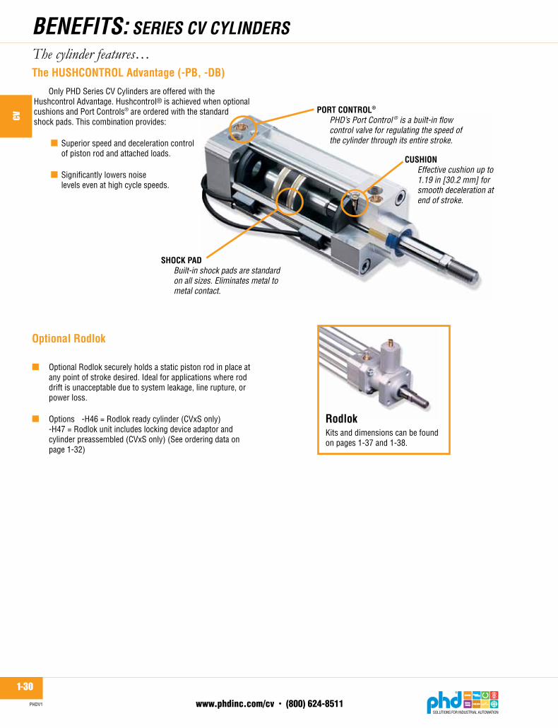
SHOCK PAD Built-in shock pads are standard on all sizes. Eliminates metal to metal contact.
CUSHION Effective cushion up to 1.19 in [30.2 mm] for smooth deceleration at
end of stroke.
PORT CONTROL®
PHD’s Port Control ® is a built-in flow control valve for regulating the speed of the cylinder through its entire stroke.
Kitsanddimensionscanbefoundonpages1-37and1-38.
Rodlok
The HUSHCONTROL Advantage (-PB, -DB)
The cylinder features…
OnlyPHDSeriesCVCylindersareofferedwiththeHushcontrolAdvantage.Hushcontrol®isachievedwhenoptionalcushionsandPortControls®areorderedwiththestandardshockpads.Thiscombinationprovides: ■ Superiorspeedanddecelerationcontrol
ofpistonrodandattachedloads.
■ Significantlylowersnoiselevelsevenathighcyclespeeds.
Optional Rodlok

1-31www.phdinc.com/cv • (800) 624-8511
CV
PHDV1
sERiEs CvA oR CvB 3 position CYLiNdERs
■ SeriesCVAandCVBareavailableas3positionunits.
sERiEs CvA CYLiNdERs 32-100 mm iso 6431
■ Standard32mmthrough 100mmboreunitsconform
toISO6431andVDMA24562specifications.
■ Availableinboresizes20mmand25mm.ConformstoISO6432customerinterfaceandoverallunitlengthwhenspecifiedwithoptional-Por-Qmounting.(metricunits)
sERiEs CvC CYLiNdERs20 & 25 mm iso 6432
sERiEs CvB CYLiNdERs20 & 25 mm
■ Availableinboresizes20mmand25mm.CustomerinterfaceconformstoISO6432forrodandmounting.(metricunits)
PRodUCT sELECTioN GUidE: sERiEs Cv CYLiNdERs
sERiEs CvA oR CvB doUBLE Rod ENd CYLiNdERs
■ SeriesCVAandCVBareavailableasdoublerodendunits.

1-32www.phdinc.com/cv • (800) 624-8511
CV
PHDV1
oRdERiNG dATA: sERiEs Cv CYLiNdERs
NO
TES:
1)-Z
1 op
tion
may
hav
e re
duce
d cy
linde
r per
form
ance
due
to c
hrom
e-pl
ated
sta
inle
ssst
eel r
od in
pla
ce o
f chr
ome-
plat
ed a
lloy
stee
l.2)
-H46
& -H
47 is
not
ava
ilabl
e in
-Z1.
3) *
For m
ount
ing
acce
ssor
ies
and
dim
ensi
ons,
see
Acc
esso
ries
Sect
ion.
4)M
arke
d op
tions
pro
vide
add
ition
al c
ylin
der f
lexi
bilit
y, b
ut d
o no
t dim
ensi
onal
lyco
mpl
y w
ith th
e IS
O 6
431/
VDM
A 24
562
or IS
O 6
432
spec
ifica
tions
.5)
Impe
rial u
nit p
rovi
des
impe
rial p
orts
, rod
end
s, a
nd s
trok
e. M
ount
ings
are
met
ric.
6) F
or s
witc
h in
form
atio
n, s
ee s
witc
h op
tion
page
and
Sw
itche
s Se
ctio
n.7)
On
3 po
sitio
n un
its, p
orts
, opt
ions
-DB
and/
or -P
B ar
e av
aila
ble
in lo
catio
ns 1
and
5on
ly. C
onta
ct P
HD
for o
ther
con
figur
atio
ns. S
ee o
ptio
n pa
ges.
8)Cu
stom
er in
terf
ace
conf
orm
s to
ISO
643
2, b
ut lo
nger
leng
th th
an IS
O 6
432.
9)Cu
stom
er in
terf
ace
and
leng
ths
conf
orm
to IS
O 6
432
with
opt
iona
l -P
or -Q
mou
ntin
g sp
ecifi
ed o
n CV
C on
ly.
x
TO O
RD
ER, S
PECI
FY:
Prod
uct,
Serie
s, T
ype,
Des
ign
No.
,M
ount
ing
styl
e, B
ore
size
, Str
oke,
and
any
Opt
ions
.
STR
OKE
LEN
GTH
S(1
5 m
m (5
/8")
= m
inim
um s
trok
ein
1 m
m (1
/8")
incr
emen
ts)
MO
DEL
NU
MBE
R-
--
CUSH
ION
CO
NTR
OL
DB
-Cus
hion
Con
trol
s Bo
th E
nds
DE
-Cus
hion
Con
trol
Ex
tend
Onl
yD
R-C
ushi
on C
ontr
ol
Ret
ract
Onl
ySt
anda
rd c
ushi
on c
ontro
llo
catio
ns a
re 1
& 5
.Se
e no
te 7
.
OPT
ION
AL P
ORT
LO
CATI
ON
UB0
0 - P
orts
on
all s
ides
, bot
h en
ds (N
ot a
vaila
ble
with
Por
t Con
trol
s on
sam
e en
d) C
onta
ct P
HD
For
oth
erco
mbi
natio
ns. S
tand
ard
port
loca
tions
are
1 &
5.
See
note
7.
BOR
E[m
m]
CVC2
0CV
C25
CVB2
0CV
B25
32 40 50 63 80 100
MET
RIC
MAX
IMU
MST
RO
KE m
m50
050
075
075
010
0010
0010
0010
0010
0010
00Co
ntac
t PH
D fo
r sho
rter
or lo
nger
str
okes
.
TYPE
S - S
ingl
e R
od, d
oubl
eac
ting
(Sta
ndar
d)D
- D
oubl
e R
od,
doub
le a
ctin
g (N
otav
aila
ble
on 3
posi
tion
units
.)PR
OD
UCT
C - C
ylin
der
MO
UN
TIN
G S
TYLE
P-
Rea
r piv
ot in
pos
ition
5Q
-R
ear p
ivot
in p
ositi
on 6
V-
Stan
dard
mou
ntin
g4
fem
ale
thre
ads
each
end
per
ISO
64
31/V
DM
A 24
562
& IS
O 6
432*
(-P
and
-Q a
vaila
ble
on 2
0 &
25
mm
bor
es o
nly)
P6
VBC
20S
25PB
DB
UB0
0M
-Z1
SER
IES
SIZE
S 32
-100
mm
VA -
VDM
A 24
562
ISO
643
115
0 ps
i [10
bar
] Air
DES
IGN
NO
.2
-Im
peria
l
(See
not
e 5.
)6
- Met
ric
BOR
E SI
ZE
mm 20 25 32 40 50 63 80 100
in .787
.984
1.26
1.58
1.97
2.48
3.15
3.94
sq m
m31
449
180
412
5719
6331
1750
2778
54
sq in
.486
.760
1.25
1.95
3.05
4.83
7.79
12.1
7
BOR
EPI
STO
N A
REA
PORT
CO
NTR
OL®
BUIL
T-IN
MET
ER O
UT
FLO
W C
ON
TRO
L VA
LVE
PB -
Port
Con
trol
s Bo
th E
nds
PE -
Port
Con
trol
Ext
end
Onl
yPR
- Po
rt Co
ntro
l Ret
ract
Onl
ySt
anda
rd p
ort c
ontr
ollo
catio
ns a
re 1
& 5
.Se
e no
te 7
.
CYLI
ND
ER O
PTIO
NS
F22
-4
Wre
nch
Flat
s on
Rod
F44
-N
o W
renc
h Fl
ats
on R
odH
46-
Rod
lok
read
y cy
linde
r (CV
xS o
nly)
See
Not
e 2.
H47
-R
odlo
k un
it in
clud
es lo
ckin
g de
vice
Adap
tor a
nd C
ylin
der p
reas
sem
bled
(CVx
S on
ly) S
ee N
ote
2.K_
-Ex
tra
Rod
Ext
ensi
onin
5 m
m (5
/8")
incr
emen
ts. L
engt
h co
deis
K5
= 5
mm
(5/8
"), K
15 =
15
mm
(1-7
/8"),
etc
.L7
-G
Por
t (BS
PP) o
n im
peria
l uni
tsL9
-N
PT P
orts
on m
etric
uni
tsM
-M
agne
tic p
isto
n fo
r use
with
PHD
Min
iatu
re R
eed
and
Solid
Sta
te S
witc
hes
T44
-Fe
mal
e R
od E
nd U
nder
size
d Th
read
T55
-Pl
ain
Rod
End
TEE
-M
ale
Rod
with
Ove
rsiz
ed T
hrea
d (C
VAx
only
)Z1
-Co
rros
ion
Res
ista
nt, c
hrom
e-pl
ated
Stai
nles
s St
eel R
od, a
nd a
ppro
pria
teco
atin
g on
ferr
ous
part
s.
Loca
tion
defin
ition
for
port
s, c
ushi
on c
ontr
ols,
and
Port
Con
trol
s®
SER
IES
SIZE
S 20
& 2
5 m
m O
NLY
VB -
ISO
643
215
0 ps
i [10
bar
] Air
See
note
8.
VC -
ISO
643
215
0 ps
i [10
bar
] Air
See
note
9.
25
STR
OKE
CYLI
ND
ER 1
Tota
l Str
oke
STR
OKE
CYLI
ND
ER 2
From
Ret
ract
to M
idPo
sitio
n (3
pos
ition
onl
y)
POSI
TIO
N 2
Mid
-Pos
ition
POSI
TIO
N 1
Full
Ret
ract
POSI
TIO
N 3
Full
Exte
nd
E
THR
EEPO
SITI
ON
UN
IT(S
peci
fy o
nly
if ne
eded
)(N
ot a
vaila
ble
on S
erie
s CV
C)Se
e no
te 7
.
REA
R P
IVO
T M
OU
NTI
NG
STY
LES
(20
and
25 m
m B
OR
ES O
NLY
)
IMPE
RIA
LM
AXIM
UM
STR
OKE
in20 20 30 30 40 40 40 40 40 40
x
RET
RAC
TEN
D
EXTE
ND
END
P M
OU
NT
Q M
OU
NT
3
2
7
6
58
1
4
!O
ptio
ns m
ay a
ffect
uni
t len
gth.
See
unit
dim
ensi
on a
nd o
ptio
nspa
ges
for a
dder
s.
1-33www.phdinc.com/cv • (800) 624-8511
CV
PHDV1
ENGiNEERiNG dATA: sERiEs Cv CYLiNdERs
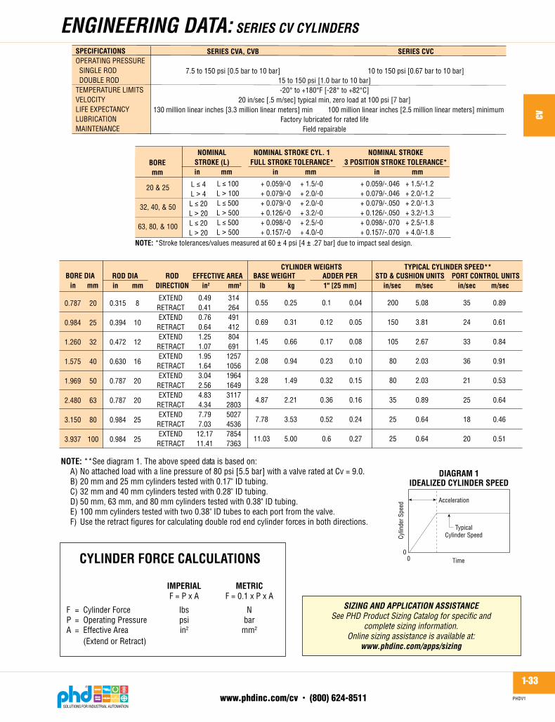
CYLINDER FORCE CALCULATIONS IMPERIAL METRIC F=PxA F=0.1xPxA
F = CylinderForce lbs NP = OperatingPressure psi barA = EffectiveArea in2 mm2
(ExtendorRetract)
siZiNG ANd APPLiCATioN AssisTANCESee PHD Product Sizing Catalog for specific and
complete sizing information.Online sizing assistance is available at:
www.phdinc.com/apps/sizing
20
25
32
40
50
63
80
100
ROD DIAin mm
BORE DIA
0.315
0.394
0.472
0.630
0.787
0.787
0.984
0.984
8
10
12
16
20
20
25
25
EFFECTIVE AREAin2 mm2mm
0.787
0.984
1.260
1.575
1.969
2.480
3.150
3.937
inROD
DIRECTION
EXTENDRETRACTEXTEND
RETRACTEXTEND
RETRACTEXTEND
RETRACTEXTEND
RETRACTEXTEND
RETRACTEXTEND
RETRACTEXTEND
RETRACT
0.490.410.760.641.251.071.951.643.042.564.834.347.797.03
12.1711.41
314264491412804691
1257105619641649311728035027453678547363
BASE WEIGHTlb kg
0.55
0.69
1.45
2.08
3.28
4.87
7.78
11.03
0.25
0.31
0.66
0.94
1.49
2.21
3.53
5.00
CYLINDER WEIGHTSADDER PER1" [25 mm]
0.1
0.12
0.17
0.23
0.32
0.36
0.52
0.6
0.04
0.05
0.08
0.10
0.15
0.16
0.24
0.27
STD & CUSHION UNITSin/sec m/sec
TYPICAL CYLINDER SPEED**PORT CONTROL UNITS
in/sec m/sec
200
150
105
80
80
35
25
25
5.08
3.81
2.67
2.03
2.03
0.89
0.64
0.64
35
24
33
36
21
25
18
20
0.89
0.61
0.84
0.91
0.53
0.64
0.46
0.51
NOTE: *Stroke tolerances/values measured at 60 � 4 psi [4 � .27 bar] due to impact seal design.
SPECIFICATIONSOPERATING PRESSURE SINGLE ROD DOUBLE RODTEMPERATURE LIMITSVELOCITYLIFE EXPECTANCYLUBRICATIONMAINTENANCE
15 to 150 psi [1.0 bar to 10 bar]-20� to +180�F [-28� to +82�C]
20 in/sec [.5 m/sec] typical min, zero load at 100 psi [7 bar]
Factory lubricated for rated lifeField repairable
SERIES CVA, CVB
7.5 to 150 psi [0.5 bar to 10 bar]
130 million linear inches [3.3 million linear meters] min
SERIES CVC
10 to 150 psi [0.67 bar to 10 bar]
100 million linear inches [2.5 million linear meters] minimum
20 & 25
32, 40, & 50
63, 80, & 100
L � 100L � 100L � 500L � 500L � 500L � 500
BOREmm
NOMINALSTROKE (L)in mm
NOMINAL STROKE CYL. 1FULL STROKE TOLERANCE*
in mm
+ 0.059/-0+ 0.079/-0+ 0.079/-0+ 0.126/-0+ 0.098/-0+ 0.157/-0
+ 1.5/-0+ 2.0/-0+ 2.0/-0+ 3.2/-0+ 2.5/-0+ 4.0/-0
L���4L � 4L � 20L � 20L � 20L � 20
NOMINAL STROKE3 POSITION STROKE TOLERANCE*
in mm
+ 0.059/-.046+ 0.079/-.046+ 0.079/-.050+ 0.126/-.050+ 0.098/-.070+ 0.157/-.070
+ 1.5/-1.2+ 2.0/-1.2+ 2.0/-1.3+ 3.2/-1.3+ 2.5/-1.8+ 4.0/-1.8
DIAGRAM 1IDEALIZED CYLINDER SPEED
TypicalCylinder Speed
Acceleration
00
Cylin
der S
peed
Time
NOTE: **See diagram 1. The above speed data is based on:A) No attached load with a line pressure of 80 psi [5.5 bar] with a valve rated at Cv = 9.0.B) 20 mm and 25 mm cylinders tested with 0.17" ID tubing.C) 32 mm and 40 mm cylinders tested with 0.28" ID tubing.D) 50 mm, 63 mm, and 80 mm cylinders tested with 0.38" ID tubing.E) 100 mm cylinders tested with two 0.38" ID tubes to each port from the valve.F) Use the retract figures for calculating double rod end cylinder forces in both directions.
1-34www.phdinc.com/cv • (800) 624-8511
CV
PHDV1
Alldimensionsarereferenceonlyunlessspecificallytoleranced.
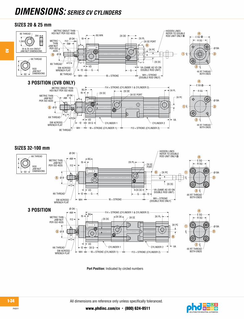
dimENsioNs: sERiEs Cv CYLiNdERs
METRIC THINJAM NUT
PER ISO 4035f12
f9BG
KK THREADSW ACROSS
WRENCH FLAT
VDf2
WH f8 + STROKE (CYLINDER 1)
3X G
2X DC 3X EE2X DE
f14 + STROKE (CYLINDER 1 & CYLINDER 2)
3X PL
3X PC
VA
f13 + STROKE (CYLINDER 2)4X RT THREAD
BOTH ENDS
E SQR SQ
2X PL
B2
A
KK THREAD
B2
A
KK THREAD
4X RT THREADBOTH ENDS
E SQR SQ
�
5
6
1 3
2
4
1 3
4
2
1
3
4
2
1
3
4
5
5
6
6
2
METRIC THINJAM NUT
PER ISO 4035
METRICTHIN
JAM NUTPER ISO
4035
METRIC THINJAM NUT
PER ISO 4035
WH + STROKE(DOUBLE ROD ONLY)
AM
��B
2X DC
AM
CL
CL
f12f9
BG
KK THREAD
SW ACROSSWRENCH FLAT
VDf2
f8 + STROKE
G G f2
VA (SAME AS VD ONDOUBLE ROD UNIT)
WH + STROKE(DOUBLE ROD ONLY)
2X EEPORT
HIDDEN LINESREFER TO DOUBLEROD UNIT ONLY
2X PC
AM
���
2X DE2X PL
2X DC
CL
CL
f9BG MIN
BE THREAD
SW ACROSSWRENCH FLAT
VDf2
WH f8 + STROKE
G G 4X RT THREADBOTH ENDS
E SQR SQ2X EE PORT
2X PC
METRIC SNOUT THINHEX NUT PER ISO 4035
20 & 25 mm SNOUTJAM NUT DIMENSIONS
1.260
BE THREAD.394
AM
��B
f9BG
f14 + STROKE (CYLINDER 1 & CYLINDER 2)
2X DC
3X PC
4X RT THREADBOTH ENDS
CL
CL
E SQ
R SQ
SW ACROSSWRENCH FLAT
f2VD
2X DE3X EE PORT
3X PL
f8 + STROKE (CYLINDER 1)
VA
f13 + STROKE (CYLINDER 2)
SIZES 20 & 25 mm
SIZES 32-100 mm
KK THREAD
KK THREAD
BE THREAD
3X G
3 POSITION (CVB ONLY)
3 POSITION
2X DE
C
C
RODJAM NUTDIMENSIONS
C
RODJAM NUTDIMENSIONS
C
CL
CL
WH
VA (SAME AS VD ONDOUBLE ROD UNIT)
HIDDEN LINESREFER TO DOUBLEROD UNIT ONLY
CYLINDER 1 CYLINDER 2
CYLINDER 1 CYLINDER 2
WH
� DK
� DK
��DK
��DK
� BA
��BA
��BA
��BA
� B
f12
f12
METRIC SNOUT THINHEX NUT PER ISO 4035
Port Position:Indicatedbycirclednumbers

1-35www.phdinc.com/cv • (800) 624-8511
CV
PHDV1
Alldimensionsarereferenceonlyunlessspecificallytoleranced.
M22
x 1
.5
M4
x 0.
7
1.29
91.
535
2.16
51.
125
2.16
5
.787
.446
.630
1.33
9.9
844.
528
1/2
NPT
—1.
437
5.43
3— — .268
.394
7.00
812
.441
1.65
43/
4-16
.472
.866
3.50
4
.827
.157
.177
2.00
8
1.29
91.
535
1.77
21.
125
1.77
2
.787
.446
.591
1.18
1.9
843.
858
3/8
NPT
—1.
319
5.03
9— — .268
.394
6.77
211
.811
1.49
63/
4-16
.394
.709
2.83
5
.827
.157
.177
1.81
1
.866
.906
1.37
8.7
501.
378
.709
.323
.374
1.08
3.6
302.
205
1/4
NPT
— .807
4.13
4— — .169
.256
4.82
38.
957
1.35
81/
2-20
.236
.728
1.49
6
.512
.157
.177
1.1
81
26.7
531
.045
.024
.045
.0
20.0
8.0
9.0
30.5
20.0
80.0
G 3
/812
.027
.512
1.0
— — 5.7
8.0
157.
027
8.0
38.0
M16
x 1
.510
.020
.056
.5
16.0
4.0
4.5
37.0
.650
.827
.866
.562
.866
.472
.210
.226
.559
.394
1.57
51/
8 N
PT— .748 —
2.75
62.
520
.142
.236
3.62
26.
378
.787
3/8-
24.1
77.3
541.
063
.315
.079
.079
1.10
2
18.9
21.0
22.0
17.0
22.0
12.0
5.0
5.7
14.2
10.0
40.0
G 1
/88.
019
.0— 70
.064
.03.
66.
092
.016
2.0
20.0
M10
x 1
.25
4.5
9.0
27.0
8.0
2.0
2.0
28.0
M22
x 1
.5
M4
x 0.
7
—
M8
x 1.
25
1.08
31.
220
1.57
5.9
381.
575
.787
.387
.394
1.04
3.7
872.
697
1/4
NPT
—1.
083
4.17
3— — .224
.315
5.72
89.
902
1.35
85/
8-18
.236
.728
1.83
1
.630
.157
.177
1.45
7
—
M8
x 1.
25
—
M10
x 1
.5
—
M10
x 1
.5
—
M6
x 1
18.9
21.0
30.0
17.0
30.0
18.0
5.0
7.0
24.5
12.0
49.5
G 1
/88.
018
.594
.0— — 4.
26.
011
1.0
205.
031
.0M
10 x
1.2
55.
016
.032
.5
10.0
4.0
4.5
26.0
—
M6
x 1
21.1
23.0
35.0
19.0
35.0
18.0
6.0
9.5
27.5
16.0
56.0
G 1
/49.
020
.510
5.0
— — 4.3
6.5
122.
522
7.5
34.5
M12
x 1
.25
6.0
18.5
38.0
13.0
4.0
4.5
30.0
.577
.748
.866
.500
.866
.472
.195
.190
.581
.315
1.45
71/
8 N
PT— .669 —
2.63
82.
323
.142
.196
3.50
46.
142
.787
5/16
-24
.167
.354
1.02
4
.276
.079
.079
.945
LETT
ERD
IM
BOR
E SI
ZE32
mm
NO
TES:
1)U
nles
s ot
herw
ise
dim
ensi
oned
, mou
ntin
g ho
le p
atte
rns
are
cent
ered
on
the
cylin
der.
2)Po
rts
and
cush
ions
may
app
ear o
n ei
ther
sid
e of
the
cylin
der c
ente
rline
bas
ed o
n op
tion
com
bina
tions
.3)
**Al
l met
ric (C
Vxx6
) uni
ts, e
xcep
t por
t with
Por
t Con
trol
® o
n sa
me
side
, com
ply
with
ISO
160
30 a
nd D
IN 3
852
part
2 p
ort s
peci
ficat
ions
for s
hort
stu
d an
d la
rge
seal
ing
surfa
ce.
See
Port
Con
trol
® o
ptio
n sh
eet f
or p
ort a
nd P
ort C
ontr
ol® d
imen
sion
s on
uni
ts w
ith p
orts
and
Por
t Con
trol
s® o
n th
e sa
me
side
.4)
*WH
val
ues
are
dete
rmin
ed w
ith c
ylin
der a
t 60
± 4
psi [
4 ±
.27
bar]
due
to im
pact
sea
l des
ign.
5)
***
Mar
ked
dim
ensi
ons
on th
e pr
evio
us p
age
prov
ide
addi
tiona
l fle
xibi
lity,
but d
o no
t dim
ensi
onal
ly c
ompl
y w
ith IS
O 6
431/
VDM
A 24
562
or IS
O 6
432
spec
ifica
tions
.
A AM Ø B B2 BA BE
BG m
inC
DC*
**D
E***
DK E
EE P
ORT
**EE
G P
ORT
DEP
THf2
f8 C
VAf8
CVB
f8 C
VCf9 f1
2f1
3f1
4 G KKPC
***
PL**
*R RT SW VA VD WH
*
.650
.827
1.18
1.5
621.
181
.709
.210
.276
.965
.472
1.94
91/
8 N
PT— .728
3.70
1— — .165
.236
4.37
08.
071
1.22
03/
8-24
.197
.630
1.28
0
.394
.157
.177
1.02
4
26.8
31.0
40.0
24.0
40.0
20.0
8.0
10.0
26.5
20.0
68.5
G 1
/49.
027
.510
6.0
— — 5.7
8.0
145.
525
1.5
34.5
M16
x 1
.56.
018
.546
.5
16.0
4.0
4.5
37.0
1.08
31.
220
1.77
2.9
381.
772
.787
.387
.354
1.20
1.7
873.
150
3/8
NPT
—1.
083
4.76
4— — .224
.315
6.18
110
.945
1.49
65/
8-18
.394
.787
2.22
4
.630
.157
.177
1.45
7
33.0
39.0
45.0
30.0
45.0
20.0
10.0
15.0
30.0
25.0
98.0
G 3
/812
.033
.512
8.0
— — 6.8
10.0
172.
030
0.0
38.0
M20
x 1
.510
.018
.072
.0
21.0
4.0
4.5
46.0
33.0
39.0
55.0
30.0
55.0
20.0
10.0
16.0
34.0
25.0
115.
0G
1/2
14.0
36.5
138.
0— — 6.
810
.017
8.0
316.
042
.0M
20 x
1.5
12.0
22.0
89.0
21.0
4.0
4.5
51.0
inm
m25
mm
20 m
m
14.4
19.0
22.0
13.0
22.0
12.0
4.0
4.8
14.8
8.0
37.0
G 1
/88.
017
.0— 67
.059
.03.
65.
089
.015
6.0
20.0
M8
x 1.
254.
29.
026
.0
7.0
2.0
2.0
24.0
inm
m40
mm
inm
m50
mm
inm
m63
mm
80 m
m10
0 m
min
mm
inm
min
mm
inm
m
dimENsioNs: sERiEs Cv CYLiNdERs

1-36www.phdinc.com/cv • (800) 624-8511
CV
PHDV1
Thisoptionomitsrodendwrenchflats.Ifthisoptionisspecifiedondoublerodunits,bothrodendswillbesuppliedwithoutwrenchflats.
Withthisoption,therodissuppliedwithfourrodendflatsinsteadofthestandardtwoflats.Ifthisoptionisspecifiedondoublerodunits,bothrodendswillbesuppliedwithfourwrenchflats.
NO WRENCH FLATS ON ROD ENDF44
4 WRENCH FLATS ON ROD ENDF22
F44 STANDARD F22
oPTioNs: sERiEs Cv CYLiNdERs
PHDcushionsaredesignedforsmoothdecelerationattheendofstroke.Whenthecushionisactivated,theremainingvolumeinthecylindermustexhaustpastanadjustableneedlewhichcontrolstheamountofdeceleration.Theeffectivecushionlengthsforeachboresizeareshowninthetablebelow.Tospecifydifferentcushioncontrollocationsontheheadorcap,seeoptioncodeabove.
Note:Cushioncontrolson3positionunitsareavailableonlywith-DBoptioninlocations1and5only.3positionunitswillhavecushiononfullextendandfullretract.
CUSHION CONTROL IN BOTH DIRECTIONS (standardlocation1&5,seenote)
DBCUSHION CONTROL ON EXTEND ONLY (standardlocation1,notavailableon3positionunits)
DE
CUSHION CONTROL ON RETRACT ONLY (standardlocation5,notavailableon3positionunits)
DR
Cushion Control LocationsB - Both endsE - Extend end onlyR - Retract end only
CUSHION CONTROL OPTIONS -D x x x
Retract Location(5, 6, 7, 8)
Omit if -DEx
Extend Location(1, 2, 3, 4)
Omit if -DRx
RETRACTEND
EXTENDEND
RETRACTEND
EXTENDEND
3
2
7
6
5
8
1
4
3
2
7
6
8
1
4
5
Unitshownis-DB25,cushioninlocation2onextendendandcushioninlocation5onretractend.(Portsareshowninstandardlocations1&5.)Cushioncontrollocationson3positionunitsare1and5onlyandwillreceiveacontrolontheheadandintermediateheadonly.
Unitshownis-DR6,cushioninlocation6onretractendandnoneonextendend.(Portsareshowninstandardlocations1&5.)
Formetricunits(CVxx6).ThisoptiondoesnotdimensionallycomplywiththeISO6431/VDMA24562orISO6432specifications.
DE
DC
DH HEXACROSS FLATS DE
DC
SOME PORT CONTROL & CUSHIONOPTION COMBINATIONS WILL MOVECUSHION CONTROLS TO THIS LOCATION.DIMENSIONS ARE REFERENCE ONLY.LOCATIONS MAY VARY.
DCDEDH
EFFECTIVECUSHION LENGTH
LETTERDIM
BORE SIZE32 mm 50 mm 63 mm 80 mm
in mm
.276
.965—
.598
40 mm
7.024.52.5
15.2
100 mmin mm
.3741.083
—
.807
9.527.52.5
20.5
in mm
.3941.043
—
.870
10.026.52.5
22.1
in mm
.3541.201
—
.870
9.030.52.5
20.4
in mm
.5911.181
—
.894
15.030.03.0
22.7
in mm
.6301.339
—
1.189
16.034.03.0
30.2
25 mmin mm
.226
.561
.561
.469
5.714.22.5
11.9
20 mmin mm
.190
.581—
.441
4.814.82.5
11.2
Alldimensionsarereferenceonlyunlessspecificallytoleranced.

1-37www.phdinc.com/cv • (800) 624-8511
CV
PHDV1
20253240506380100
BOREmm
ADAPTORKIT*
63459-07-163459-08-163459-01-163459-02-163459-03-163459-04-163459-05-163459-06-1
LOCKINGDEVICE
KIT
63460-07-163460-08-163460-01-163460-02-163460-03-163460-04-163460-05-163460-06-1
COMPLETERODLOK*
63461-07-163461-08-163461-01-163461-02-163461-03-163461-04-163461-05-163461-06-1
NOTES:1) * Kits ship with cylinder mounting hardware.2) Rodlok® is intended for use only on -H46 cylinder.3) Imperial port adaptor converts port from G1/8 to 1/8" NPT for use
with -L9 cylinders or imperial units.4) **Adaptor must be ordered separately. Required to convert to
imperial port.STATIC LOCKING FORCE*
20253240506380100
BOREmm
79901352253374956741124
35040060010001500220030005000
RODLOK KITS
NOTE: *Locking force given in table isthe actual locking force with a dry, cleanrod and does not include any safety factor.
IMPERIALPORT
ADAPTOR**
——
63465-163465-163465-163465-163465-163465-1
2
1 3
2
1 3
2
1 3
OPTIONAL PRESSURESENSOR/SWITCH
Plumbing Schematic Example:lb N
oPTioNs: sERiEs Cv CYLiNdERs
PHD’sRodlokisidealforlockingthepistonrodwhileinastatic/stationaryposition.WhenthepressureisremovedfromtheportoftheRodlok,themechanismwillgriptherodandpreventitfrommoving.Theloadsareheldindefinitelywithoutpower.Rodlokperformanceisapplicationandenvironmentsensitive(cleanlinessofrodorRodlokwillalsoaffectperformance).THERODLOKISNOTDESIGNEDTOBEUSEDASAPERSONNELSAFETYDEVICE.
Option -H46providesaRodlokreadycylinderwithappropriaterodextensionandmaterialsforusewithPHD’sRodlok.
Option -H47providesacylinderandRodlokpre-assembled.TheportfortheRodlokwillbeassembledinthesamepositionastheportontheextendendofthecylinder.
TheRodloklockingdeviceandadaptorcanbepurchasedseparatelyaskits.Seechartatright.Thelockingdeviceandadaptorarenot available with the -Z1 corrosion resistant finish.
Dimensionscontinuedonnextpage.
RODLOK READY CYLINDER Availableonsinglerodunitsonly.(Rodloksoldseparately)
H46
RODLOK CYLINDER & RODLOK Availableonsinglerodunitsonly.(preassembled)
H47
OPERATING PRESSURETheoperatingpressureforthelockingdeviceisdifferentthan
theoperatingpressureforthecylinderwiththeRodlokattached.ThelockingdeviceoftheRodlokisdesignedwithanoperatingpressurerangeof60psiminimumto150psimaximum[4to10bar].TheSeriesCVCylinderwithaRodlokattachedhasanoperatingpressurerangeof22psiminimumto150psimaximum[1.5to10bar].
ThepneumaticschematicaboveshowstypicalvalvingforcylinderandRodlokforbothhorizontalandverticaloperation.Theschematicshowsthree3/2wayvalves,oneforeachportonthecylinderandonefortheRodlokport.Theuseoftwovalvesonthecylinderallowsforbothportstobepressurizedwhenvalvesarede-energized.Theuseofanin-lineregulatorallowsthecylinderportstobepressurizedatdifferentpressures.Thisallowsthecylindertobalanceouttheopposingpressureandforceoftheattachedload.Oncepistonrodmotionhasstopped,theRodlokcanbeengagedbyde-energizingitsvalveandreleasingitspressure.TheuseofcheckvalvesandbuiltinPHDPortControls®isrecommended.Pressureswitchshownisoptionalandapplicationspecific.
Formetricunits(CVxx6).ThisoptiondoesnotdimensionallycomplywiththeISO6431/VDMA24562orISO6432specifications.

1-38www.phdinc.com/cv • (800) 624-8511
CV
PHDV1
ThisoptionprovidesNPTportsinsteadofthestandardG(BSPP)ports.TheNPTportsarelocatedinthesamelocationastheG(BSPP)ports.
NPT PORTS (Metric Units)
L920253240506380
100
BORE[mm]
IMPERIALNPT PORT
METRICBSPP PORT
1/8*1/8*1/81/41/43/83/81/2
G 1/8*G 1/8*G 1/8G 1/4G 1/4G 3/8G 3/8G 1/2
*When Port Controls® (-PB, -PR, -PE)are specified on the same face as port,the ports change to M5 on metric and10-32 on imperial.
NOTES:1) -H47 units have Rodlok port aligned with cylinder port on extend.2) See pages 1-34 and 1-35 for complete cylinder dimensions.3) * = Port supplied on Rodlok device, requires port adaptor from page 1-37 to convert to 1/8 NPT.4) All dimensions not noted are standard. See pages 1-34 and 1-35 for complete cylinder dimensions.
M6 x 1 x 20M6 x 1
M5G 1/8*
M6 x 1 x 20M6 x 1
M5G 1/8*
M8 x 1.25 x 30M8 x 1.25
M6G 1/8*
M8 x 1.25 x 30M8 x 1.25
M8G 1/8*
M10 x 1.5 x 30M10 x 1.5
M8G 1/8*
M10 x 1.5 x 30M10 x 1.5
M8G 1/8*
M22 x 1.5
M4 x 0.7 x 20M4 x 0.7
—M5 x 0.8
M22 x 1.5
M4 x 0.7 x 20M4 x 0.7
—M5 x 0.8
A1A2A3A4B
BEC
D1D3DKEF
F2G1G2G3H1L1L3L5L6L7L8
L10L11WH
LETTERDIM
BORE SIZE32 mm 50 mm 63 mm 80 mm 100 mm
in mm1.2801.575.165.630
1.890—
1.9691.181
—.472.984.984
3.346.315.472
1.8902.2831.260.630.315
2.9131.024
40 mm
32.540.04.2
16.048.0—
50.030.0—
12.025.025.0
85.08.0
12.048.058.032.016.08.0
74.026.0
1.4961.811.177.827
2.205—
2.2831.378
—.630
1.0831.142
3.839.394.472
2.1652.5591.398.768.394
3.3461.181
38.046.04.521.056.0—
58.035.0—
16.027.529.0
97.510.012.055.065.035.519.510.085.030.0
1.8312.126.453.9452.677
—2.7561.575
—.7871.2801.378
4.626.591.6302.7563.2281.929.827.4724.2131.457
46.554.011.524.068.0—
70.040.0—
20.032.535.0
117.515.016.070.082.049.021.012.0107.037.0
2.2242.165.2951.2603.228
—3.3461.772
—.7871.6141.673
5.256.591.5912.7563.2281.929.827.4724.2131.457
56.555.07.532.082.0—
85.045.0—
20.041.042.5
133.515.015.070.082.049.021.012.0107.037.0
2.8352.756.3941.7323.937
—4.1341.772
—.9841.9292.067
6.752.630.6303.5434.3312.4411.102.6305.3541.811
72.070.010.044.0100.0
—105.045.0—
25.049.052.5
171.516.016.090.0110.062.028.016.0136.046.0
89.070.010.060.0
120.0—
130.055.0—
25.053.065.0
189.016.018.092.0
115.065.027.016.0
143.051.0
3.5042.756.3942.3624.724
—5.1182.165
—.9842.0872.559
7.441.630.7093.6224.5282.5591.063.6305.6302.008
in mm in mm in mm in mm in mm
20 mm
in mm1.024
———
1.457
1.457.866.590.315.807.728
2.795.354.3541.5752.2441.142.433—
2.520.945
26.0———
37.0
37.022.015.08.020.518.5
71.09.09.040.057.029.011.0—
64.024.0
25 mm
in mm1.063
———
1.575
1.575.866.669.394.807.787
2.854.315.3151.7322.4801.220.512—
2.8351.102
27.0———
40.0
40.022.017.010.020.520.0
72.58.08.0
44.063.031.013.0—
72.028.0
oPTioNs: sERiEs Cv CYLiNdERs
RODLOK DIMENSIONS(continuedfrompreviouspage)
H1
F
CA1
BA1
A4
E SQ
Ø D1
Ø DK
L11L6
L5
L7L8
4X F2 FASTENER
SEE NOTE 4
L3 L1
A24X G2 THDX DEPTH L10
A3
WH4X G1 THD
G3 PORT
BE THREADX D3 MIN LONG
(20 & 25 BORE ONLY)
ThisoptiondoesnotdimensionallycomplywiththeISO6431/VDMA24562orISO6432specifications.
ThisoptionprovidesG(BSPP)portsinsteadofthestandardNPTports.TheG(BSPP)portsarelocatedinthesamelocationastheNPTports.
BSPP PORTS (Imperial Units)
L7
Alldimensionsarereferenceonlyunlessspecificallytoleranced.

1-39www.phdinc.com/cv • (800) 624-8511
CV
PHDV1
A*BCDEFGHI
LETTERDIM
BORE SIZE32 mm 50 mm 63 mm 80 mm
in mm40 mm 100 mm
in mm in mm in mm in mm in mm
1.969.276.295.2361.949.374—
.8701.146
D
E SQ
F
C
B
D
A SQ*E SQ
BF
G
C
63, 80, & 100 mm units32, 40, & 50 mm units
50.07.07.56.049.59.5—
22.129.1
2.283.197.256.2362.205.374—
.8701.087
58.05.06.56.056.09.5—
22.127.6
2.756.236.276.2362.697.374—
.8701.106
70.06.07.06.068.59.5—
22.128.1
3.346.236.335.2363.150.37417�.8311.059
85.06.08.56.080.09.517�21.126.9
4.134.157.295.2363.858.37420�.819.965
105.04.07.56.098.09.520�20.824.5
5.118.020.315.2364.528.37424�.795.811
130.00.58.06.0
115.09.524�20.220.6
NOTE: *ISO/VDMA max square size
Connector Detail.236
.200.170
.870.525
CABLE
Connector Detail
H I
25 mmin mm
1.339.441.323.2361.575.374—
.8701.311
34.011.28.26.040.09.5—
22.133.3
20 mmin mm
1.339.343.283.2361.457.374—
.8701.213
34.08.77.26.037.09.5—
22.130.8
20 & 25 mm units
A SQ*
D
E SQ
FC B
A SQ
oPTioNs: sERiEs Cv CYLiNdERs
Extrarodextensioncanbeachievedbyspecifyingtheoption-Kfollowedbythelengthcode.Rodextensionisavailablein1/8"or5mmincrements.Ifthisoptionisspecifiedondoublerodunits,bothrodendswillbesuppliedwiththesameextrarodextension.ContactPHDforothercombinations.
EXTRA ROD EXTENSIONK_
MAGNET FOR PHD MINIATURE REED AND SOLID STATE SWITCHES
M
62505-1-02
62506-1-02
62515-1
62516-1
PART NO. DESCRIPTION COLORNPN (Sink) DC Solid State,2 m cablePNP (Source) DC Solid State,2 m cableNPN (Sink) DC Solid State,Quick ConnectPNP (Source) DC Solid State,Quick Connect
Brown
Tan
Brown
Tan
SERIES 6250 SOLID STATE SWITCHES
62507-1-0262517-1
PART NO. DESCRIPTION COLORAC/DC Reed, 2 m cableAC/DC Reed, Quick Connect
SilverSilver
SERIES 6250 REED SWITCHES
20253240506380100
BORE[mm]
0.9451.1021.0241.1811.4571.4571.8112.008
24.028.026.030.037.037.046.051.0
WHin mmK_
WH + K_
Byspecifyingthisoption,astainlesssteelrodwithhardchromeplatingissuppliedinplaceofthestandardhardchromeplatedsteelmaterial.Appropriatecoatingissuppliedonferrousparts.
CORROSION RESISTANTZ1
ImperialK5=5/8"extrarodextensionK15=1-7/8"extrarodextension
ThisoptionequipsthecylinderwithamagneticbandonthepistonforusewithPHDMiniatureReedandSolidStateSwitcheslistedbelow.Theseswitchesmounteasilytothecylinderusing“T”slotsinthebody.SeeSwitchesandSensorssectionforcompleteswitchinformation.Threepositionunitswillreceiveamagnetonbothcylinder1andcylinder2whenspecifiedwith-Moption.
MetricK5=5mmextrarodextensionK15=15mmextrarodextension
Length CodeFormetricunits(CVxx6).ThisoptiondoesnotdimensionallycomplywiththeISO6431/VDMA24562orISO6432specifications.
Alldimensionsarereferenceonlyunlessspecificallytoleranced.
1-40www.phdinc.com/cv • (800) 624-8511
CV
PHDV1
oPTioNs: sERiEs Cv CYLiNdERs
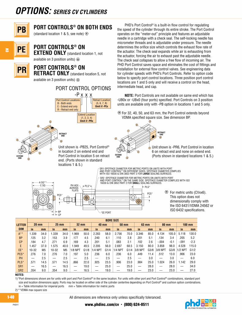
PHD’sPortControl®isabuilt-inflowcontrolforregulatingthespeedofthecylinderthroughitsentirestroke.ThePortControloperatesonthe“meter-out”principleandfeaturesanadjustableneedleinacartridgewithacheckseal.Theself-lockingneedlehasmicrometerthreadsandisadjustableunderpressure.Theneedledeterminestheorificesizewhichcontrolstheexhaustflowrateoftheactuator.Thechecksealexpandswhileairisexhaustingfromtheactuator,forcingtheairtoexhaustpasttheadjustableneedle.Thechecksealcollapsestoallowafreeflowofincomingair.ThePHDPortControlsavesspaceandeliminatesthecostoffittingsandinstallationforexternalflowcontrolvalves.SeeengineeringdataforcylinderspeedswithPHD’sPortControls.Refertooptioncodebelowtospecifyportcontrollocations.Threepositionportcontrollocationsare1and5onlyandwillreceiveacontrolonthehead,intermediatehead,andcap. NOTE: PortControlsarenotavailableonsameendwhichhas-UB0xor-UBx0(fourports)specified.PortControlson3positionunitsareavailableonlywith-PBoptioninlocations1and5only.
For32,40,50,and63mm,thePortControlextendsbeyondVDMAspecifiedsquaresize.SeedimensionBP.
PORT CONTROLS® ON BOTH ENDS(standardlocation1&5,seenote)
PB
PORT CONTROLS® ON EXTEND ONLY (standardlocation1,not
availableon3positionunits)
PE
PORT CONTROLS® ON RETRACT ONLY (standardlocation5,not
availableon3positionunits)
PR
PH HEXACROSS
FLATS
*EE PORT
A SQ**E SQ
PLS*PLS*
PCS*PCS*
BPCP
SR1-SPOTFACE DIAMETER FOR METRIC PORTS ON UNITS WITH PORTAND PORT CONTROL® ON DIFFERENT SIDES. SPOTFACE DIAMETER COMPLIESWITH ISO 16030 & DIN 3852 PART 2 FOR LARGE SEALING SURFACES.
SR2 -SPOTFACE DIAMETER FOR METRIC PORTS ON UNITS WITH PORTAND PORT CONTROL® ON THE SAME SIDE. SPOTFACE DIAMETER COMPLIES WITH ISO16030 & DIN 3852 PART 2 FOR SMALL SEALING SURFACES.
A**BPCPE
EE*PCS*
PHPLS*SR1SR2
LETTERDIM
BORE SIZE32 mm 50 mm 63 mm 80 mm 100 mm
in mm
40 mm
1.969.177.169
1.9491/8 NPT
.197—
.866——
50.04.54.3
49.5G1/85.02.5
22.019.016.5
2.283.240.201
2.2051/4 NPT
.236—
.925——
58.06.15.1
56.0G1/46.02.5
23.525.019.0
2.756.110.083
2.6971/4 NPT
.236—
.906——
70.02.82.1
68.5G1/46.02.5
23.025.019.0
3.346.201.102
3.1503/8 NPT
.449—
.984——
85.05.12.6
80.0G3/811.43.0
25.028.023.0
4.134.134-.0043.858
3/8 NPT.512—
1.024——
105.03.4-0.198.0G3/813.03.0
26.028.023.0
5.118.205-.0914.528
1/2 NPT.906—
1.142——
130.05.2-2.3
115.0G1/223.06.0
29.034.027.0
in mm in mm in mm in mm in mm
NOTES:1)*Port dimensions shown are for units with port and Port Control® in the same location. For units with other port and Port Control® combinations, standard port
size and location dimensions apply. Ports may be located on either side of the cylinder centerline depending on Port Control® and cushion option combinations.in = Table information for imperial ports mm = Table information for metric ports
2)**VDMA max square size
25 mm
in mm1.339.153.2711.57510-32.276—
.571—
.354
34.03.96.9
40.0M57.02.5
14.516.59.0
20 mm
in mm1.339.125.1841.45710-32.276—
.571—
.354
34.03.24.737.0M57.02.514.516.59.0
Port Control LocationsB - Both endsE - Extend end onlyR - Retract end only
PORT CONTROL OPTIONS-P x x x
Retract Location(5, 6, 7, 8)
Omit if -PEx
Extend Location(1, 2, 3, 4)
Omit if -PRx
RETRACTEND
EXTENDEND
RETRACTEND
EXTENDEND
3
2
7
6
5
8
1
4
3
2
7
6
5
8
1
4
Unitshownis-PB25,PortControl®inlocation2onextendendandPortControlinlocation5onretractend.(Portsshowninstandardlocations1&5.)
Unitshownis-PR6,PortControlinlocation6onretractendandnoneonextendend.(Portsshowninstandardlocations1&5.)
Formetricunits(CVxx6).ThisoptiondoesnotdimensionallycomplywiththeISO6431/VDMA24562orISO6432specifications.
Alldimensionsarereferenceonlyunlessspecificallytoleranced.
1-41www.phdinc.com/cv • (800) 624-8511
CV
PHDV1
oPTioNs: sERiEs Cv CYLiNdERs
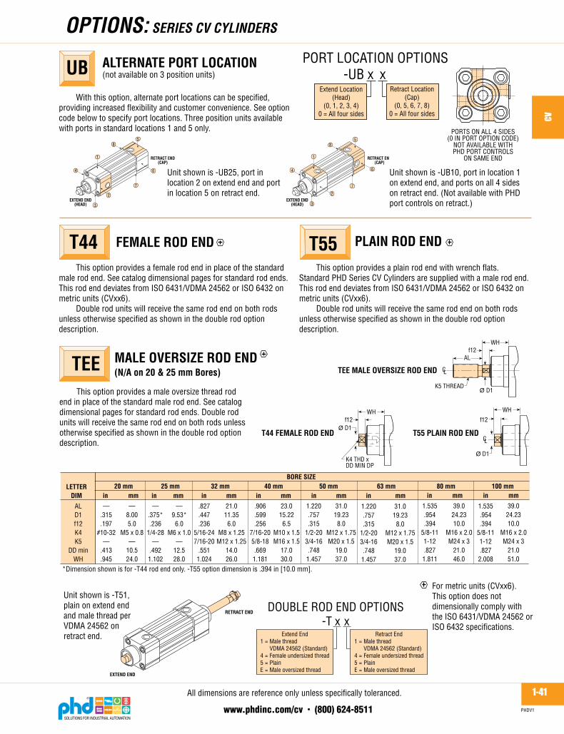
Thisoptionprovidesafemalerodendinplaceofthestandardmalerodend.Seecatalogdimensionalpagesforstandardrodends.ThisrodenddeviatesfromISO6431/VDMA24562orISO6432onmetricunits(CVxx6).
Doublerodunitswillreceivethesamerodendonbothrodsunlessotherwisespecifiedasshowninthedoublerodoptiondescription.
FEMALE ROD ENDT44 PLAIN ROD ENDT55Thisoptionprovidesaplainrodendwithwrenchflats.
StandardPHDSeriesCVCylindersaresuppliedwithamalerodend.ThisrodenddeviatesfromISO6431/VDMA24562orISO6432onmetricunits(CVxx6).
Doublerodunitswillreceivethesamerodendonbothrodsunlessotherwisespecifiedasshowninthedoublerodoptiondescription.
Withthisoption,alternateportlocationscanbespecified,providingincreasedflexibilityandcustomerconvenience.Seeoptioncodebelowtospecifyportlocations.Threepositionunitsavailablewithportsinstandardlocations1and5only.
ALTERNATE PORT LOCATION(notavailableon3positionunits)UB
Extend Location(Head)
(0, 1, 2, 3, 4)0 = All four sides
PORT LOCATION OPTIONS -UB x x
Retract Location(Cap)
(0, 5, 6, 7, 8)0 = All four sides
RETRACT END(CAP)
EXTEND END(HEAD)
RETRACT END(CAP)
EXTEND END(HEAD)3
2
7
6
58
1
4
3
2
7
6
58
1
4Unitshownis-UB25,portinlocation2onextendendandportinlocation5onretractend.
Unitshownis-UB10,portinlocation1onextendend,andportsonall4sidesonretractend.(NotavailablewithPHDportcontrolsonretract.)
PORTS ON ALL 4 SIDES(0 IN PORT OPTION CODE)
NOT AVAILABLE WITHPHD PORT CONTROLS
ON SAME END
f12WH
T44 FEMALE ROD END
WH
T55 PLAIN ROD ENDØ D1
f12
Ø D1
TEE MALE OVERSIZE ROD END
f12WH
K5 THREAD
AL
Ø D1
K4 THD xDD MIN DP
CL
CL
1.535.954.394
5/8-111-12.827
2.008
ALD1f12K4K5
DD minWH
LETTERDIM
BORE SIZE32 mm 50 mm 63 mm 80 mm 100 mm40 mm
.827
.447
.2365/16-247/16-20
.5511.024
21.011.35
6.0M8 x 1.25M12 x 1.25
14.026.0
.906
.599
.2567/16-205/8-18.669
1.181
23.015.22
6.5M10 x 1.5M16 x 1.5
17.030.0
1.220.757.315
1/2-203/4-16.748
1.457
31.019.23
8.0M12 x 1.75M20 x 1.5
19.037.0
1.220.757.315
1/2-203/4-16.748
1.457
31.019.23
8.0M12 x 1.75M20 x 1.5
19.037.0
1.535.954.394
5/8-111-12.827
1.811
39.024.2310.0
M16 x 2.0M24 x 3
21.046.0
39.024.2310.0
M16 x 2.0M24 x 3
21.051.0
in mm in mm25 mm
in mm
—.375*.236
1/4-28—
.4921.102
—9.53*
6.0M6 x 1.0
—12.528.0
20 mmin mm
—.315.197
#10-32—
.413
.945
—8.005.0
M5 x 0.8—
10.524.0
*Dimension shown is for -T44 rod end only. -T55 option dimension is .394 in [10.0 mm].
in mm in mm in mm in mm
Unitshownis-T51,plainonextendendandmalethreadperVDMA24562onretractend. Extend End
1 = Male threadVDMA 24562 (Standard)
4 = Female undersized thread5 = PlainE = Male oversized thread
DOUBLE ROD END OPTIONS-T x x
Retract End1 = Male thread
VDMA 24562 (Standard)4 = Female undersized thread5 = PlainE = Male oversized thread
RETRACT END
EXTEND END
Thisoptionprovidesamaleoversizethreadrodendinplaceofthestandardmalerodend.Seecatalogdimensionalpagesforstandardrodends.Doublerodunitswillreceivethesamerodendonbothrodsunlessotherwisespecifiedasshowninthedoublerodoptiondescription.
MALE OVERSIZE ROD END(N/A on 20 & 25 mm Bores)TEE
Formetricunits(CVxx6).ThisoptiondoesnotdimensionallycomplywiththeISO6431/VDMA24562orISO6432specifications.
Alldimensionsarereferenceonlyunlessspecificallytoleranced.
1-42www.phdinc.com/cv • (800) 624-8511
CV
PHDV1
moUNTiNG sTYLEs: sERiEs Cv CYLiNdERs
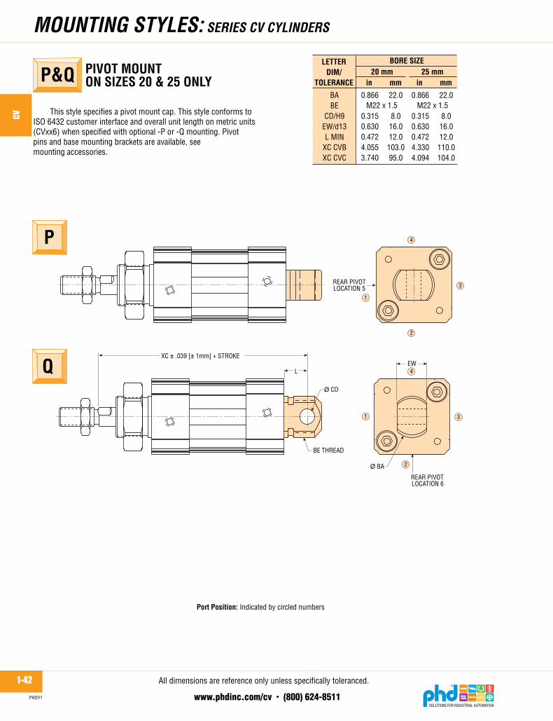
Thisstylespecifiesapivotmountcap.ThisstyleconformstoISO6432customerinterfaceandoverallunitlengthonmetricunits(CVxx6)whenspecifiedwithoptional-Por-Qmounting.Pivotpinsandbasemountingbracketsareavailable,seemountingaccessories.
PIVOT MOUNT ON SIZES 20 & 25 ONLYP&Q
P
Q
BE THREAD
XC � .039 [� 1mm] + STROKE
L
� CD
EW
� BA
REAR PIVOTLOCATION 5
REAR PIVOTLOCATION 6
2
1 3
4
2
1
3
4
BABE
CD/H9EW/d13L MIN
XC CVBXC CVC
LETTERDIM/
TOLERANCE
BORE SIZE25 mm
in mm
0.866
0.3150.6300.4724.3304.094
22.0
8.016.012.0110.0104.0
20 mmin mm
0.866
0.3150.6300.4724.0553.740
22.0
8.016.012.0103.095.0
M22 x 1.5 M22 x 1.5
Alldimensionsarereferenceonlyunlessspecificallytoleranced.
Port Position:Indicatedbycirclednumbers

1-43www.phdinc.com/cv • (800) 624-8511
CV
PHDV1
moUNTiNG sTYLEs: sERiEs Cv CYLiNdERs
STANDARD MOUNTING (ISO 6431/VDMA 24562 & ISO 6432 for metric units CVxx6)
4X RT THREAD BOTHENDS BG DEEP
BE THREAD20 & 25 ONLY
KK THREAD
R SQ
BA DIA
f8 + STROKEWF/WHWG/f2
AM
AMBABE
BG minf8 CVAf8 CVBf8 CVC
KKRRTWFWHWGf2
LETTER DIM/TOLERANCE
BORE SIZE32 mm 50 mm 63 mm 80 mm40 mm 100 mm
in mm20 mm
0.7480.866
0.472—
2.6382.323
5/16-241.024
0.945
0.669
19.022.0
12.0—
67.059.0
M8 x 1.2526.0
24.0
17.0
M22 x 1.5
M4 x 0.7
—
—
in mmin mmin mmin mmin mm25 mm
in mm
0.8270.866
0.472—
2.7562.5203/8-241.063
1.102
0.748
21.022.0
12.0—
70.064.0
M10 x 1.2527.0
28.0
19.0
M22 x 1.5
M4 x 0.7
—
—
0.8271.181
0.7093.701
——
3/8-241.280
1.024
0.728
21.030.0
18.094.0——
M10 x 1.2532.5
26.0
18.5
—
M6 x 1—
—
0.9061.378
0.7094.134
——
1/2-201.496
1.181
0.807
23.035.0
18.0105.0
——
M12 x 1.2538.0
30.0
20.5
—
M6 x 1—
—
1.2201.575
0.7874.173
——
5/8-181.831
1.457
1.083
31.040.0
20.0106.0
——
M16 x 1.546.5
37.0
27.5
—
M8 x 1.25—
—
1.2201.772
0.7874.764
——
5/8-182.224
1.457
1.083
31.045.0
20.0121.0
——
M16 x 1.556.5
37.0
27.5
—
M8 x 1.25—
—
1.5351.772
0.7875.039
——
3/4-162.835
1.811
1.319
39.045.0
20.0128.0
——
M20 x 1.572.0
46.0
33.5
—
M10 x 1.5—
—
1.5352.165
0.7875.433
——
3/4-163.504
2.008
1.437
39.055.0
20.0138.0
——
M20 x 1.589.0
51.0
36.5
—
M10 x 1.5—
—
in mm
V
Alldimensionsarereferenceonlyunlessspecificallytoleranced.

1-44www.phdinc.com/cv • (800) 624-8511
CV
PHDV1
moUNTiNG ACCEssoRiEs: sERiEs Cv CYLiNdERs
SELF-ALIGNING PISTON ROD COUPLERS - METRIC
BENEFITS■ RodCouplerseliminateexpensiveprecisionmachiningfor
mountingfixedorrigidcylinderonguideorslideapplications.
■ Cylinderefficiencyisincreasedbyeliminatingfrictioncausedbymisalignment.Couplerscompensatefor2°angularerrorand1/32"[0.8mm]lateralmisalignmentonpushandpullstroke.
■ Couplersprovidegreaterreliabilityandreducecylinderandcomponentwear,simplifyingalignmentproblemsinthefield.
■ RodCouplersaremanufacturedfromhightensileandhardenedsteelcomponents.
New metric rod couplers are an ideal accessory for use with
Series CV ISO/VDMA cylinders.
Toorder,specifythemodelnumber.
M8
M10
—
M12
M16
M20
A
LETTER DIMENSIONMODEL NO.
B min1.00
[25.4]1.00
[25.4]
1.13
1.13[28.6]1.75
[44.5]1.75
[44.5]
C min0.625[15.9].625
[15.9]
.650
.650[16.5]1.125[28.5]1.125[28.5]
D min1.875[47.6]1.875[47.6]
2.187
2.187[55.5]3.312[84.1]3.312[84.1]
E0.500[12.7]
.50[12.7]
.50
.50[12.7].812
[20.6].812
[20.6]
F0.875[22.2].875
[22.2]
1.0
1.0[25.4]1.562[39.7]1.562[39.7]
IMPERIAL
.187
.219
.250
.312
.375
.421
NOTES:1) NUMBERS IN [ ] ARE mm. IMPERIAL EQUIVALENTS ARE PROVIDED FOR CONVENIENCE.2) *UNITS SHOWN ARE WITH STANDARD ROD ENDS. OPTIONAL ROD ENDS MAY USE OTHER MODEL NUMBERS.
5/16-24[M8 x 1.25]
3/8-24[M10 x 1.25]
7/16-20
1/2-20[M12 x 1.25]
5/8-18[M16 x 1.5]
3/4-16[M20 x 1.5]
GA THREAD
.032 [0.8] LATERALCOMPENSATION
2° ANGULAR COMPENSATION
B C
D
A INTERNAL THREADX E DEEP
F DIA CL
METRIC.197[5.0].197[5.0]
—
.236[6.0].314[8.0].394
[10.0]
GIMPERIAL METRIC
312
375
437
500
625
750
CV CYLINDER BORE*IMPERIAL
20
25, 32
—
40
50, 63
80, 100
METRIC
20
25, 32
—
40
50, 63
80, 100
CL
.032 [0.8]LATERAL
COMPENSATION
2� ANGULARCOMPENSATION
Alldimensionsarereferenceonlyunlessspecificallytoleranced.
1-45www.phdinc.com/cv • (800) 624-8511
CV
PHDV1
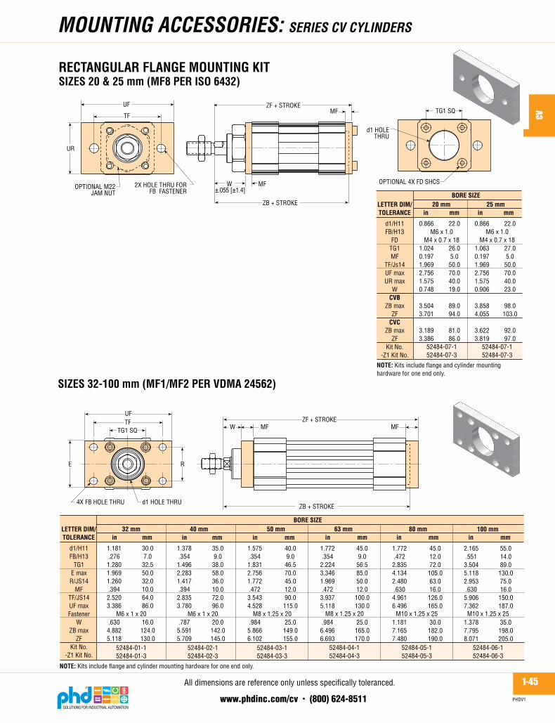
RECTANGULAR FLANGE MOUNTING KIT SIZES 20 & 25 mm (MF8 PER ISO 6432)
moUNTiNG ACCEssoRiEs: sERiEs Cv CYLiNdERs
ZF + STROKEMFW
ZB + STROKE
MF
UFTF
TG1 SQ
E
4X FB HOLE THRU d1 HOLE THRU
R
2X HOLE THRU FORFB FASTENER
OPTIONAL M22JAM NUT
OPTIONAL 4X FD SHCS
UF
TF
UR
d1 HOLETHRU
TG1 SQ
ZB + STROKE
W MF
ZF + STROKEMF
�.055 [�1.4]
d1/H11FB/H13
TG1E maxR/JS14
MFTF/JS14UF maxFastener
WZB max
ZFKit No.
-Z1 Kit No.
LETTER DIM/TOLERANCE
BORE SIZE32 mm 50 mm 63 mm 80 mm
in mm
1.181.2761.2801.9691.260.3942.5203.386
.6304.8825.118
40 mm
30.07.0
32.550.032.010.064.086.0
16.0124.0130.0
1.378.354
1.4962.2831.417.394
2.8353.780
.7875.5915.709
35.09.0
38.058.036.010.072.096.0
20.0142.0145.0
1.575.354
1.8312.7561.772.472
3.5434.528
.9845.8666.102
40.09.0
46.570.045.012.090.0
115.0
25.0149.0155.0
1.772.354
2.2243.3461.969.472
3.9375.118
.9846.4966.693
45.09.0
56.585.050.012.0
100.0130.0
25.0165.0170.0
1.772.472
2.8354.1342.480.630
4.9616.496
1.1817.1657.480
100 mm
45.012.072.0
105.063.016.0
126.0165.0
30.0182.0190.0
2.165.551
3.5045.1182.953.630
5.9067.362
1.3787.7958.071
55.014.089.0
130.075.016.0
150.0187.0
35.0198.0205.0
in mm
M6 x 1 x 20
52484-01-152484-01-3
M6 x 1 x 20
52484-02-152484-02-3
M8 x 1.25 x 20
52484-03-152484-03-3
in mm in mm
M8 x 1.25 x 20
52484-04-152484-04-3
M10 x 1.25 x 25
52484-05-152484-05-3
in mm
M10 x 1.25 x 25
52484-06-152484-06-3
in mm
M6 x 1.0M4 x 0.7 x 18
52484-07-152484-07-3
d1/H11FB/H13
FDTG1MF
TF/Js14UF maxUR max
WCVB
ZB maxZF
CVCZB max
ZFKit No.
-Z1 Kit No.
LETTER DIM/TOLERANCE
BORE SIZE20 mm
0.866
1.0240.1971.9692.7561.5750.748
3.5043.701
3.1893.386
in mm25 mm
in mm
22.0
26.05.0
50.070.040.019.0
89.094.0
81.086.0
M6 x 1.0M4 x 0.7 x 18
52484-07-152484-07-3
0.866
1.0630.1971.9692.7561.5750.906
3.8584.055
3.6223.819
22.0
27.05.0
50.070.040.023.0
98.0103.0
92.097.0
NOTE: Kits include flange and cylinder mountinghardware for one end only.
NOTE: Kits include flange and cylinder mounting hardware for one end only.
SIZES 32-100 mm (MF1/MF2 PER VDMA 24562)
Alldimensionsarereferenceonlyunlessspecificallytoleranced.

1-46www.phdinc.com/cv • (800) 624-8511
CV
PHDV1
moUNTiNG ACCEssoRiEs: sERiEs Cv CYLiNdERs
BASE MOUNTING KITSIZES 20 & 25 mm (MS3 PER ISO 6432)
2X DIA ABPER END
AUSA + STROKE
XU�.055
[�1.4 mm]
XA + STROKE
USTR
NH
AO
TG1
Kit can only be mounted in orientation shown.
�.008[�.2 mm]
AB/H13AO maxAU max
NHSA CVBSA CVC
TG1TR/Js14US maxXA CVBXA CVC
XUKit No.
-Z1 Kit No.
LETTER DIM/TOLERANCE
BORE SIZE20 mm
in mm0.2600.3150.7870.9844.2133.8981.0241.5752.1654.3704.0550.157
25 mmin mm
52487-07-152487-07-3
6.68.020.025.0107.099.026.040.055.0111.0103.04.0
0.2600.3150.7870.9844.3304.0941.0631.5752.1654.6454.4090.315
6.68.0
20.025.0
110.0104.027.040.055.0
118.0112.08.0
52487-07-152487-07-3
NOTE: Kits include bracket and cylinder mounting hardware forone end only.
SIZES 32-100 mm (MS1 PER VDMA 24562)
TG1 SQ
AH
TR
E
ABTG1
E maxTR
AO maxAUAHATSAXA
FastenerKit No.
-Z1 Kit No.
LETTER DIM/TOLERANCE
BORE SIZE32 mm 50 mm 63 mm 80 mm
in mm
.2701.2801.9691.260.433.9451.260.1775.5915.669
40 mm 100 mmin mm
M6 x 1 x 2052487-01-152487-01-3
in mm in mm in mm in mm
6.8732.550.032.011.024.032.04.5
142.0144.0
.3691.4962.2831.417.5911.1021.417.1776.3396.417
9.3738.058.036.015.028.036.04.5
161.0163.0
M6 x 1 x 2052487-02-152487-02-3
.3691.8312.7561.772.5911.2601.772.2176.6936.890
9.3746.570.045.015.032.045.05.5
170.0175.0
M8 x 1.25 x 2552487-03-152487-03-3
.3692.2243.3461.969.591
1.2601.969.217
7.2837.480
9.3756.585.050.015.032.050.05.5
185.0190.0
M8 x 1.25 x 2552487-04-152487-04-3
.4492.8354.1342.480.787
1.6142.480.256
8.2688.465
11.4172.0
105.063.020.041.063.06.5
210.0215.0
M10 x 1.5 x 2552487-05-152487-05-3
.5383.5045.1182.953.984
1.6142.795.256
8.6619.055
13.6689.0
130.075.025.041.071.06.5
220.0230.0
M10 x 1.5 x 2552487-06-152487-06-3
XA + STROKE
SA + STROKE2X AB DIA PER END AO
AT
AU ±.008 [±.2 mm]
NOTE: Kits include bracket and cylinder mounting hardware for one end only.
Alldimensionsarereferenceonlyunlessspecificallytoleranced.

1-47www.phdinc.com/cv • (800) 624-8511
CV
PHDV1
BB minDD
ZT CVAZT CVBZT CVC
TGKit No.
-Z1 Kit No.
LETTERDIM
BORE SIZE32 mm 50 mm 63 mm 80 mm
.669
5.394——
1.280
40 mm 100 mmin mm
ZT + STROKE
17.0
137.0——
32.5
.669
5.984——
1.496
17.0
152.0——
38.0
.906
6.535——
1.831
23.0
166.0——
46.5
.906
7.126——
2.224
23.0
181.0——
56.5
1.102
7.953——
2.835
28.0
202.0——
72.0
1.102
8.543——
3.504
28.0
217.0——
89.0
BB
DD THREAD
BB TG SQ
M6 x 1.0
63480-01-163480-01-3
M6 x 1.0
63480-01-163480-01-3
M8 x 1.25
63480-02-163480-02-3
M8 x 1.25
63480-02-163480-02-3
M10 x 1.5
63480-03-163480-03-3
M10 x 1.5
63480-03-163480-03-3
M4 x 0.7
63480-04-163480-04-3
20 mm
0.512
—4.0953.7801.024
25 mm
13.0
—104.096.026.0
M4 x 0.7
63480-04-163480-04-3
0.512
—4.3704.1341.063
13.0
—111.0105.027.0
in mmin mmin mmin mmin mmin mmin mm
NOTE: Kit includes cylinder mounting hardware for one end only.
FASTENER MOUNTING KITSIZES 20 & 25 mm (MX1)SIZES 32-100 mm (MX1 PER ISO 6431)
moUNTiNG ACCEssoRiEs: sERiEs Cv CYLiNdERs
REAR FORK MOUNTING KIT SIZES 32-100 mm (MP2 PER VDMA 24562)
A maxE max
UB/h14CB/H14
TG1FL
L minCD/H9
MR maxXD
FastenerKit No.
-Z1 Kit No.
LETTER DIM/TOLERANCE
BORE SIZE32 mm 50 mm 63 mm 80 mm
in mm
2.5591.9691.7721.0241.280.866.472.394.4335.591
40 mm 100 mmin mm
NOTES:1) Kit includes rear fork, cylinder mounting fasteners, pivot pin, and pivot pin retainer clips.2) Mounting is compatible with MP4 male hinge and BMP4 pillow block.
in mm in mm in mm in mm
XD + STROKEFL �.008 [�0.2 mm]
CB
CD DIA
MR
L
TG1 SQ
UBE SQ
A
M6 x 1 x 2052485-01-152485-01-3
65.050.045.026.032.522.012.010.011.0
142.0
2.8352.2832.0471.1021.496.984.591.472.512
6.299M6 x 1 x 2052485-02-152485-02-3
72.058.052.028.038.025.015.012.013.0
160.0
3.1502.7562.3621.2601.8311.063.591.472.512
6.693M8 x 1.25 x 20
52485-03-152485-03-3
80.070.060.032.046.527.015.012.013.0
170.0
3.7403.3462.7561.5752.2241.260.787.630.669
7.480M8 x 1.25 x 20
52485-04-152485-04-3
95.085.070.040.056.532.020.016.017.0
190.0
4.5284.1343.5431.9692.8351.417.787.630.669
8.268M10 x 1.5 x 25
52485-05-152485-05-3
115.0105.090.050.072.036.020.016.017.0
210.0
5.3155.1184.3312.3623.5041.614.984.787.827
9.055M10 x 1.5 x 25
52485-06-152485-06-3
135.0130.0110.060.089.041.025.020.021.0
230.0
Alldimensionsarereferenceonlyunlessspecificallytoleranced.

1-48www.phdinc.com/cv • (800) 624-8511
CV
PHDV1
SIZES 32-100 mm (MP4 PER VDMA 24562)
NOTES:1) Rear male hinge is compatible with MP2 mounting.2) Kit includes hinge and cylinder mounting fasteners.
E maxEW max
TG1FL
L minCD/H9
MR maxXD
FastenerKit No.
-Z1 Kit No.
LETTER DIM/TOLERANCE
BORE SIZE32 mm 50 mm 63 mm 80 mm
in mm
1.9691.0241.280.866.472.394.4335.591
40 mm 100 mmin mm in mm in mm in mm in mm
XD + STROKEFL �.008 [�0.2mm]
EW
CD DIA
MR
L
TG1 SQ
E SQ
M6 x 1 x 2052486-01-152486-01-3
50.026.032.522.012.010.011.0142.0
2.2831.1021.496.984.591.472.512
6.299M6 x 1 x 2052486-02-152486-02-3
58.028.038.025.015.012.013.0
160.0
2.7561.2601.8311.063.591.472.512
6.693M8 x 1.25 x 20
52486-03-152486-03-3
70.032.046.527.015.012.013.0
170.0
3.3461.5752.2241.260.787.630.669
7.480M8 x 1.25 x 20
52486-04-152486-04-3
85.040.056.532.020.016.017.0
190.0
4.1341.9692.8351.417.787.630.669
8.268M10 x 1.5 x 25
52486-05-152486-05-3
105.050.072.036.020.016.017.0
210.0
5.1182.3623.5041.614.984.787.827
9.055M10 x 1.5 x 25
52486-06-152486-06-3
130.060.089.041.025.020.021.0
230.0
moUNTiNG ACCEssoRiEs: sERiEs Cv CYLiNdERs
REAR MALE HINGE MOUNTING KIT SIZES 20 & 25 mm
NOTE: Kits include hinge bracket, retaining rings, pivotpins, and cylinder mounting fasteners when required.
2X THRU HOLE FORRECOMMENDED FASTENER
P OR Q MOUNTING REQUIRED
XC + STROKE�.039 [� 1mm] FL G1
G2G3
H6
CA
K2
EM
R1 RADCK DIA
M665778-01-165778-01-3
CACKEM
FL minG1G2G3H6K2R1
XC CVBXC CVCFastenerKit No.
-Z1 Kit N0.
LETTER DIM/TOLERANCE
BORE SIZE20 mm
1.1810.3150.6340.4720.6300.7871.2600.1570.9490.3944.0553.740
in mm25 mm
in mm
30.08.016.112.016.020.032.04.024.110.0103.095.0
M665778-01-165778-01-3
1.1810.3150.6340.4720.6300.7871.2600.1570.9490.3944.3304.094
30.08.016.112.016.020.032.04.024.110.0110.0104.0
Alldimensionsarereferenceonlyunlessspecificallytoleranced.
1-49www.phdinc.com/cv • (800) 624-8511
CV
PHDV1
moUNTiNG ACCEssoRiEs: sERiEs Cv CYLiNdERs
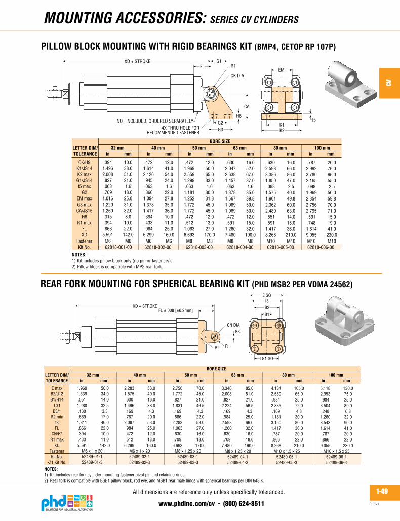
PILLOW BLOCK MOUNTING WITH RIGID BEARINGS KIT (BMP4, CETOP RP 107P)
CK/H9K1/JS14K2 maxG1/JS14f5 max
G2EM maxG3 maxCA/JS15
H6R1 max
FLXD
FastenerKit No.
LETTER DIM/TOLERANCE
BORE SIZE32 mm 50 mm 63 mm 80 mm
in mm
.3941.4962.008.827.063.7091.0161.2201.260.315.394.8665.591M6
40 mm 100 mm
NOTES:1) Kit includes pillow block only (no pin or fasteners).2) Pillow block is compatible with MP2 rear fork.
XD + STROKEFL
EMCK DIA
R1
62818-001-00
10.038.051.021.01.618.025.831.032.08.010.022.0142.0M6
.4721.6142.126.945.063.8661.0941.3781.417.394.433.9846.299M6
12.041.054.024.01.622.027.835.036.010.011.025.0160.0M6
62818-002-00 62818-003-00 62818-004-00 62818-005-00 62818-006-00
.4721.9692.5591.299.0631.1811.2521.7721.772.472.5121.0636.693M8
12.050.065.033.01.630.031.845.045.012.013.027.0170.0M8
.6302.0472.6381.457.0631.3781.5671.9691.969.472.5911.2607.480M8
16.052.067.037.01.635.039.850.050.012.015.032.0190.0M8
.6302.5983.3861.850.0981.5751.9612.3622.480.551.5911.4178.268M10
16.066.086.047.02.540.049.860.063.014.015.036.0210.0M10
.7872.9923.7802.165.0981.9692.3542.7562.795.591.7481.6149.055M10
20.076.096.055.02.550.059.870.071.015.019.041.0230.0M10
in mm in mm in mm in mm in mm
G1
CA
H6G2G3 K2
K1NOT INCLUDED, ORDERED SEPARATELY f5
4X THRU HOLE FORRECOMMENDED FASTENER
NOTES:1) Kit includes rear fork cylinder mounting fastener pivot pin and retaining rings.2) Rear fork is compatible with BSB1 pillow block, rod eye, and MSB1 rear male hinge with spherical bearings per DIN 648 K.
E maxB2/d12B1/H14
TG1B3/*
R2 minf3FL
CN/F7R1 max
XDFastenerKit No.
-Z1 Kit No.
LETTER DIM/TOLERANCE
BORE SIZE32 mm 50 mm 63 mm 80 mm
in mm
1.9691.339.551
1.280.130.669
1.811.866.394.433
5.591
40 mm 100 mmin mm in mm in mm in mm in mm
XD + STROKEFL �.008 [�0.2mm]
R1
CN DIA
TG1 SQ
E SQ
M6 x 1 x 2052489-01-152489-01-3
50.034.014.032.53.3
17.046.022.010.011.0
142.0M6 x 1 x 2052489-02-152489-02-3
M8 x 1.25 x 2052489-03-152489-03-3
M8 x 1.25 x 2052489-04-152489-04-3
M10 x 1.5 x 2552489-05-152489-05-3
M10 x 1.5 x 2552489-06-152489-06-3
2.2831.575.630
1.496.169.787
2.087.984.472.512
6.299
58.040.016.038.04.3
20.053.025.012.013.0
160.0
2.7561.772.8271.831.169.8662.2831.063.630.7096.693
70.045.021.046.54.322.058.027.016.018.0170.0
3.3462.008.8272.224.169.9842.5981.260.630.7097.480
85.051.021.056.54.325.066.032.016.018.0190.0
4.1342.559.9842.835.1691.1813.1501.417.787.8668.268
105.065.025.072.04.330.080.036.020.022.0210.0
5.1182.953.9843.504.2481.2603.5431.614.787.8669.055
130.075.025.089.06.332.090.041.020.022.0230.0
R2
B3
f3
B1
B2
REAR FORK MOUNTING FOR SPHERICAL BEARING KIT (PHD MSB2 PER VDMA 24562)
Alldimensionsarereferenceonlyunlessspecificallytoleranced.

1-50www.phdinc.com/cv • (800) 624-8511
CV
PHDV1
NOTES:1) Kit includes hinge and cylinder mounting fasteners.2) Rear male hinge is compatible with MSB2 rear fork for spherical bearing.
TG1FL/JS15
D/H7EN
ER maxL max
Z�HR
XDFastenerKit No.
-Z1 Kit No.
LETTER DIM/TOLERANCE
BORE SIZE32 mm 50 mm 63 mm 80 mm
in mm40 mm 100 mm
in mm in mm in mm in mm in mm
XD + STROKEFL
ER
D DIA
H
L SQ
M6 x 1 x 2052488-01-152488-01-3
32.522.010.014.016.050.04�——
142.0M6 x 1 x 2052488-02-152488-02-3
M8 x 1.25 x 2052488-03-152488-03-3
M8 x 1.25 x 2052488-04-152488-04-3
M10 x 1.5 x 2552488-05-152488-05-3
M10 x 1.5 x 2552488-06-152488-06-3
1.280.866.394.551.6301.969
4�——
5.591
38.025.012.016.019.058.04�——
160.0
1.496.984.472.630.7482.283
4�——
6.299
46.527.016.021.021.070.04�
51.019.0170.0
1.8311.063.630.827.8272.756
4�2.008.7486.693
56.532.016.021.024.085.04�——
190.0
2.2241.260.630.827.9453.346
4�——
7.480
72.036.020.025.028.0105.0
4�——
210.0
2.8351.417.787.9841.1024.134
4�——
8.268
89.041.020.025.030.0130.0
4�——
230.0
3.5041.614.787.9841.1815.118
4�——
9.055
R
TG1 SQ
Z�
Z�
EN+.000/-.004 [+.00/- 0.1 mm]
PILLOW BLOCK MOUNTING WITH SPHERICAL BEARING KIT (PHD BSB1 PER VDMA 24562)
CN/H7K1/JS 14K2 maxG1/JS14f5 max
G2/JS14EN
G3 maxCH/JS15
H6ER max
FLXDZ�
FastenerKit No.
LETTER DIM/TOLERANCE
BORE SIZE32 mm 50 mm 63 mm 80 mm
in mm
.3941.4962.008.827.063.709.551
1.2201.260.394.630.866
5.5914�M6
40 mm 100 mm
NOTES:1) Kit includes pillow block only. No mounting fasteners2) Pillow block is compatible with MSB2 rear fork for spherical bearing.3) Not available in -Z1.
XD + STROKEFL EN
CN DIA
ER
62822-001-00
10.038.051.021.01.6
18.014.031.032.010.016.022.0
142.04�M6
.4721.6142.126.945.063.866.630
1.3781.417.394.709.984
6.2994�M6
12.041.054.024.01.6
22.016.035.036.010.018.025.0
160.04�M6
62822-002-00 62822-003-00 62822-004-00 62822-005-00 62822-006-00
.6301.9692.5591.299.063
1.181.827
1.7721.772.472.827
1.0636.693
4�M8
16.050.065.033.01.6
30.021.045.045.012.021.027.0
170.04�M8
.6302.0472.6381.457.063
1.378.827
1.9691.969.472.906
1.2607.480
4�M8
16.052.067.037.01.6
35.021.050.050.012.023.032.0
190.04�M8
.7872.5983.3861.850.098
1.575.984
2.3622.480.551
1.1021.4178.268
4�M10
20.066.086.047.02.5
40.025.060.063.014.028.036.0
210.04�
M10
.7872.9923.7802.165.098
1.969.984
2.7562.795.591
1.1811.6149.055
4�M10
20.076.096.055.02.5
50.025.070.071.015.030.041.0
230.04�
M10
in mm in mm in mm in mm
G1
CH
H6
G2G3 K2
K1f5
Z�
Z�
4X THRU HOLE FORRECOMMENDED FASTENER
in mm
NOT INCLUDED IN KIT +.000/-.004 [+0.0/-0.1 mm]
moUNTiNG ACCEssoRiEs: sERiEs Cv CYLiNdERs
REAR MALE HINGE MOUNTING WITH SPHERICAL BEARING KIT (PHD MSB1)
Alldimensionsarereferenceonlyunlessspecificallytoleranced.
1-51www.phdinc.com/cv • (800) 624-8511
CV
PHDV1
moUNTiNG ACCEssoRiEs: sERiEs Cv CYLiNdERs
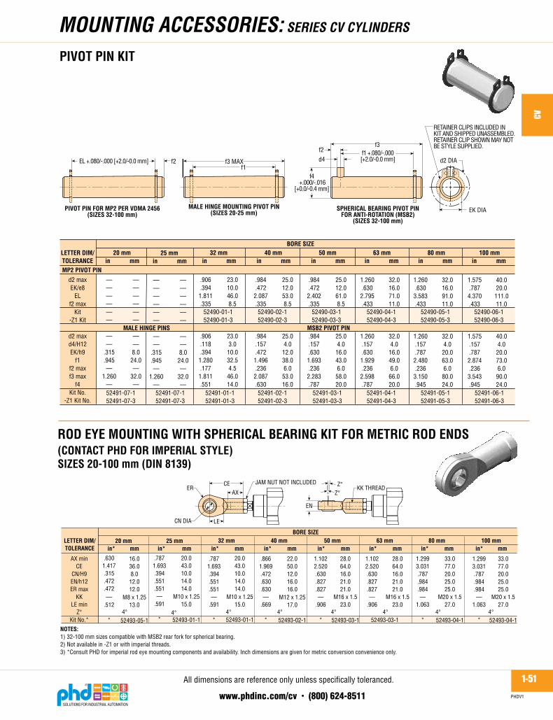
PIVOT PIN KIT
d2 DIA
EK DIA
f3f1 +.080/-.000[+2.0/-0.0 mm]
f2d4
f4 +.000/-.016
[+0.0/-0.4 mm]
RETAINER CLIPS INCLUDED INKIT AND SHIPPED UNASSEMBLED.RETAINER CLIP SHOWN MAY NOTBE STYLE SUPPLIED.
d2 maxEK/e8
ELf2 max
Kit-Z1 Kit
d2 maxd4/H12EK/h9
f1f2 maxf3 max
f4Kit No.
-Z1 Kit No.
LETTER DIM/TOLERANCE
BORE SIZE32 mm 50 mm 63 mm 80 mm
in mm40 mm 100 mm
52490-01-152490-01-3
52490-02-152490-02-3
52490-03-152490-03-3
52490-04-152490-04-3
52490-05-152490-05-3
52490-06-152490-06-3
in mm in mm in mm in mm in mmMP2 PIVOT PIN
52491-01-152491-01-3
52491-02-152491-02-3
52491-03-152491-03-3
52491-04-152491-04-3
52491-05-152491-05-3
52491-06-152491-06-3
MALE HINGE PINS
.906
.3941.811.335
.906
.118
.3941.280.1771.811.551
23.010.046.08.5
23.03.010.032.54.546.014.0
.984
.4722.087.335
.984
.157
.4721.496.2362.087.630
25.012.053.08.5
25.04.012.038.06.053.016.0
.984
.4722.402.335
.984
.157
.6301.693.2362.283.787
25.012.061.08.5
25.04.016.043.06.058.020.0
1.260.6302.795.433
1.260.157.6301.929.2362.598.787
32.016.071.011.0
32.04.016.049.06.066.020.0
1.260.6303.583.433
1.260.157.7872.480.2363.150.945
32.016.091.011.0
32.04.020.063.06.080.024.0
1.575.7874.370.433
1.575.157.7872.874.2363.543.945
40.020.0111.011.0
40.04.020.073.06.090.024.0
25 mmin mm
——————
——
.315
.945—
1.260—
——————
——8.024.0—
32.0—
20 mmin mm
——————
——
.315
.945—
1.260—
——————
——8.024.0—
32.0—
52491-07-152491-07-3
52491-07-152491-07-3
SPHERICAL BEARING PIVOT PINFOR ANTI-ROTATION (MSB2)
(SIZES 32-100 mm)
f3 MAXf1
MALE HINGE MOUNTING PIVOT PIN(SIZES 20-25 mm)
EL +.080/-.000 [+2.0/-0.0 mm] f2
PIVOT PIN FOR MP2 PER VDMA 2456(SIZES 32-100 mm)
MSB2 PIVOT PIN
ROD EYE MOUNTING WITH SPHERICAL BEARING KIT FOR METRIC ROD ENDS (CONTACT PHD FOR IMPERIAL STYLE) SIZES 20-100 mm (DIN 8139)
AX minCE
CN/H9EN/h12ER max
KKLE min
Z°Kit No.*
1.2993.031.787.984.984—
1.063
*
33.077.020.025.025.0
M20 x 1.527.0
52493-04-1
LETTER DIM/TOLERANCE
BORE SIZE32 mm 50 mm 63 mm 80 mm
.7871.693.394.551.551—
.591
*
40 mm 100 mm
NOTES:1) 32-100 mm sizes compatible with MSB2 rear fork for spherical bearing.2) Not available in -Z1 or with imperial threads.3) *Consult PHD for imperial rod eye mounting components and availability. Inch dimensions are given for metric conversion convenience only.
20.043.010.014.014.0
M10 x 1.2515.0
52493-01-1
.8661.969.472.630.630—
.669
*
22.050.012.016.016.0
M12 x 1.2517.0
52493-02-1
1.1022.520.630.827.827—
.906
*
28.064.016.021.021.0
M16 x 1.523.0
52493-03-1
1.1022.520.630.827.827—
.906
52493-03-1
28.064.016.021.021.0
M16 x 1.523.0
1.2993.031.787.984.984—
1.063
*
33.077.020.025.025.0
M20 x 1.527.0
52493-04-1
JAM NUT NOT INCLUDEDER
AXCE
LE
EN
Z°Z°
CN DIA
KK THREAD
20 mmin* mm
.6301.417.315.472.472—
.512
*
25 mm
4°
.7871.693.394.551.551—
.591
*4°
20.043.010.014.014.0
M10 x 1.2515.0
52493-01-1
in* mm in* mm in* mm in* mm in* mm in* mmin* mm
4°
16.036.08.012.012.0
M8 x 1.2513.0
52493-05-14° 4° 4° 4° 4°
Alldimensionsarereferenceonlyunlessspecificallytoleranced.

1-52www.phdinc.com/cv • (800) 624-8511
CV
PHDV1
moUNTiNG ACCEssoRiEs: sERiEs Cv CYLiNdERs
ROD CLEVIS PIVOT PIN KITSIZES 20-100 mm
RETAINER CLIPSINCLUDED IN KIT ANDSHIPPED UNASSEMBLED.RETAINER CLIP SHOWN MAYNOT BE STYLE SUPPLIED.
L1
L
d DIA
dLL1L2L3
Kit No.-Z1 Kit No.
LETTERDIM
BORE SIZE32 mm 50 mm 63 mm 80 mm
in mm
.394
.984
.791——
40 mm 100 mm
63463-01-163463-01-3
10.025.020.1——
in mm in mm in mm in mm in mm
.4721.181.949——63463-02-163463-02-3
12.030.024.1——
.6301.5351.264
——63463-03-163463-03-3
16.039.032.1——
.6301.5351.264
——63463-03-163463-03-3
16.039.032.1——
.7871.8901.579
——63463-04-163463-04-3
20.048.040.1——
.7871.8901.579
——63463-04-163463-04-3
20.048.040.1——
20 mmin mm
.315
.827—
1.2201.457
63463-05-163463-05-3
8.021.0—
31.037.0
25 mmin mm
63463-01-163463-01-3
.394
.984
.791——
10.025.020.1——
d
L2
L
L3
SIZE 20 mm SIZES 25-100 mm (DIN 8140)
AV minCE
CK/H9CL maxCM minER max
KKL
LE minMetric Kit No.*
Metric -Z1 Kit No.*
LETTER DIM/TOLERANCE
BORE SIZE32 mm 50 mm 63 mm 80 mm
in* mm
.7871.575.394.787.394.630—
.984
.787
**
40 mm 100 mm
NOTES:1) Kit includes clevis, pivot pin, and retainer rings (jam nut not included).2) *Consult PHD for imperial rod eye mounting components and availability. Inch dimensions are given for metric conversion convenience only.
20.040.010.020.010.016.0
M10 x 1.2525.020.0
52492-01-152492-01-3
in* mm in* mm in* mm in* mm in* mm
.8661.890.472.945.472.748—
1.181.945
**
22.048.012.024.012.019.0
M12 x 1.2530.024.0
52492-02-152492-02-3
1.1022.520.6301.260.630.984—
1.5351.260
**
28.064.016.032.016.025.0
M16 x 1.539.032.0
52492-03-152492-03-3
JAM NUT NOT INCLUDED
ERCE
LECK DIA
1.1022.520.6301.260.630.984—
1.5351.260
**
28.064.016.032.016.025.0
M16 x 1.539.032.0
52492-03-152492-03-3
1.2993.150.7871.575.7871.260
—1.8901.575
**
33.080.020.040.020.032.0
M20 x 1.548.040.0
52492-04-152492-04-3
1.2993.150.7871.575.7871.260
—1.8901.575
**
33.080.020.040.020.032.0
M20 x 1.548.040.0
52492-04-152492-04-3
LE
L CL CM
KK THREADX DEPTH AV
20 mm
0.6301.2600.3160.6300.3150.512
—0.8270.630
**
16.032.08.0216.08.013.0
M8 x 1.2521.016.0
52492-05-152492-05-3
25 mm
0.7871.5750.3940.7870.3940.630
—0.9840.787
**
20.040.010.0220.010.016.0
M10 x 1.2525.020.0
52492-01-152492-01-3
in* mm in* mm
RETAINER CLIPS SHOWN MAY NOT BE STYLE SUPPLIED
ROD CLEVIS MOUNTING KIT FOR METRIC ROD ENDS (CONTACT PHD FOR IMPERIAL STYLE)SIZES 20-100 mm (DIN 8140)
Alldimensionsarereferenceonlyunlessspecificallytoleranced.