Embed Size (px)
Citation preview

TABLE OF CONTENTS
DATA TABLES AND SOUND BARRIER GRAPHIC CELLS
FOR
FDOT DESIGN STANDARDS
Cell Name Index No. Title - Data Tables & Sound Barrier Graphics Cells For FDOT Design Standards
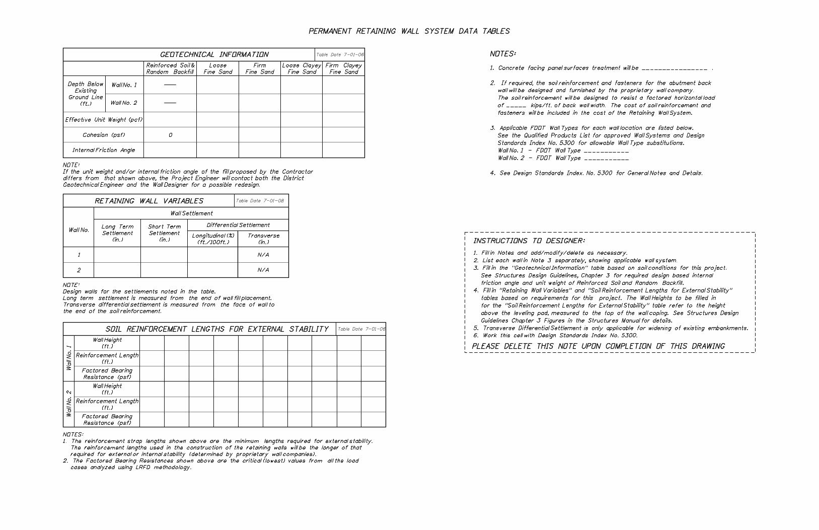
Many of the structures related Design Standards require "Data Tables" that must be completed by the designer,
which provide critical information for the contractor when these Design Standards are referenced in the contract
plans. See the "FDOT Structures Bar Menu" included with the FDOT CADD Software for the Microstation CADD
Cell Data Tables. Updates to the Data Tables for Interim Design Standards are available on the Structures Design
Office website at:
http://www.dot.state.fl.us/structures/CADD/standards/CurrentStandards/MicrostationDrawings.shtm
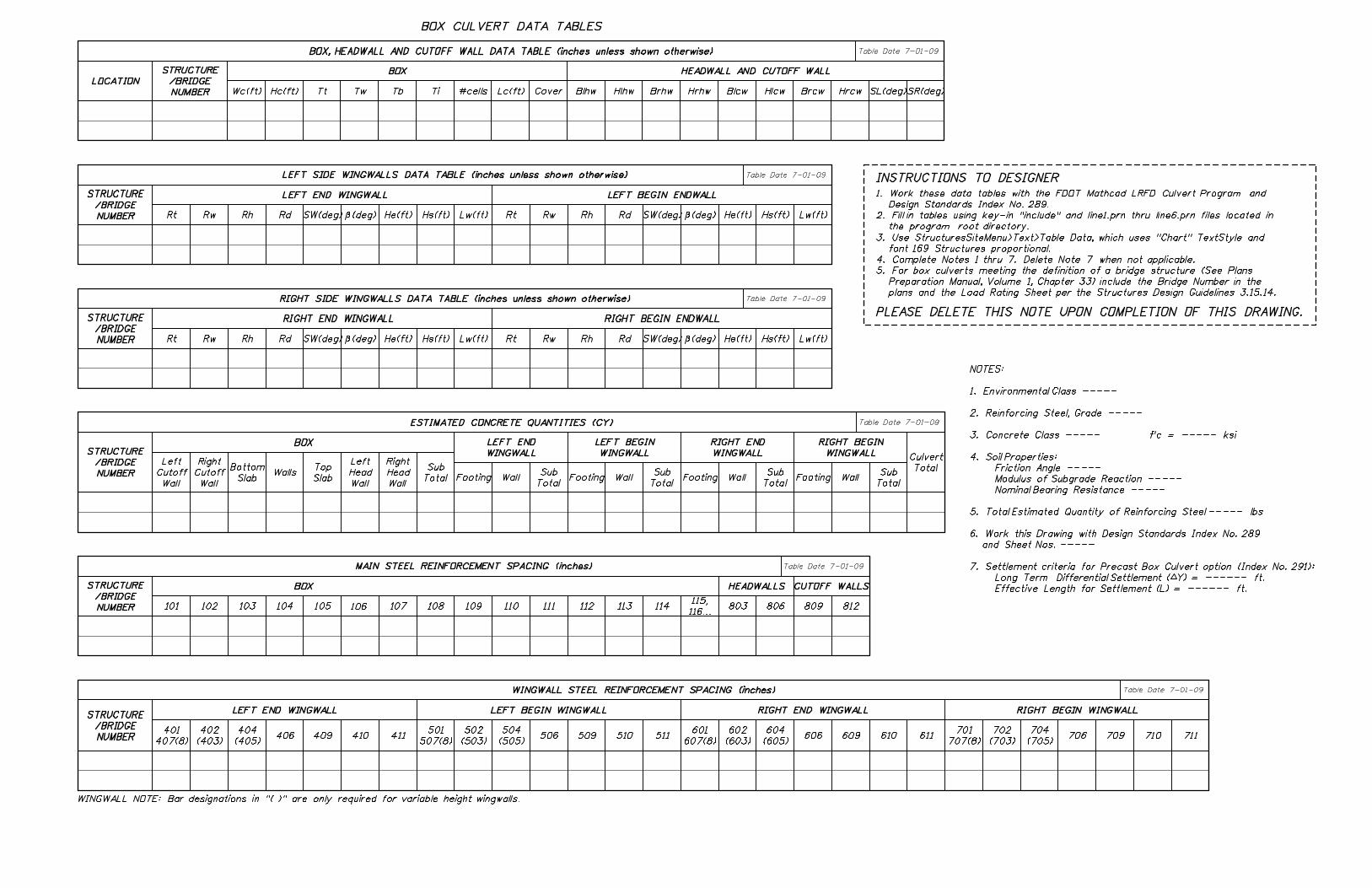
Box Culvert Data Tables
Retaining Wall Data Tables
Sound Barrier Data Tables
Brown Pelican 1 - Graphics
Brown Pelican 2 - Graphics
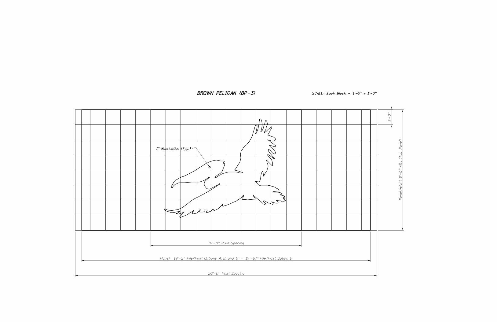
Brown Pelican 3 - Graphics
Flamingo 1 - Graphics
Flamingo 2 - Graphics
Grid Blank Wall
Laughing Gull 1 - Graphics
Laughing Gull 2 - Graphics
Laughing Gull 3 - Graphics
Sail Boat - Graphics
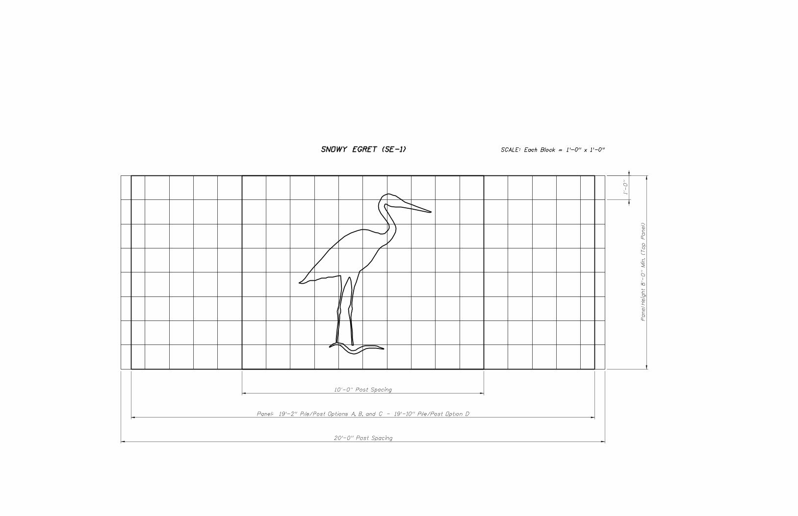
Snowy Egret 1-Graphics
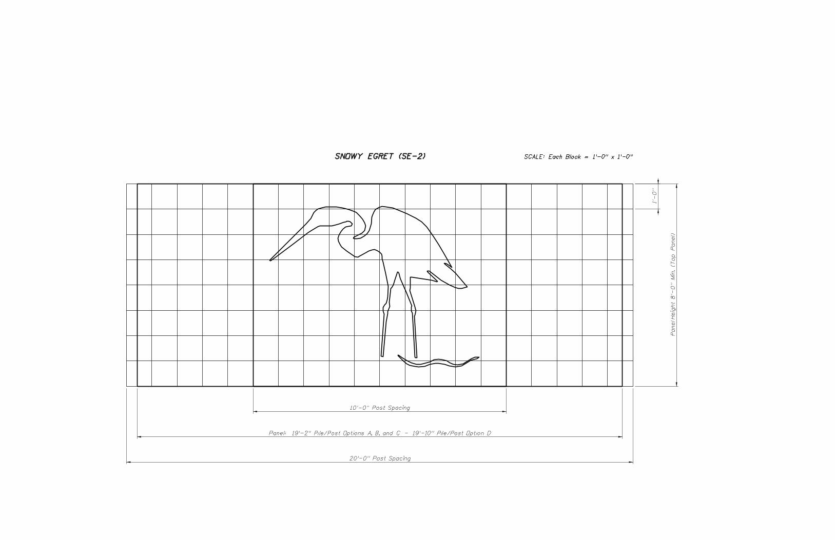
Snowy Egret 2-Graphics
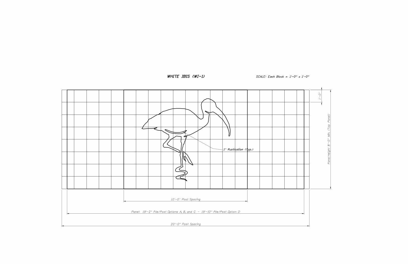
White Ibis 1-Graphics
White Ibis 2-Graphics
Retaining Wall System Data Tables (Permanent)
Retaining Wall System Data Tables (Temporary)
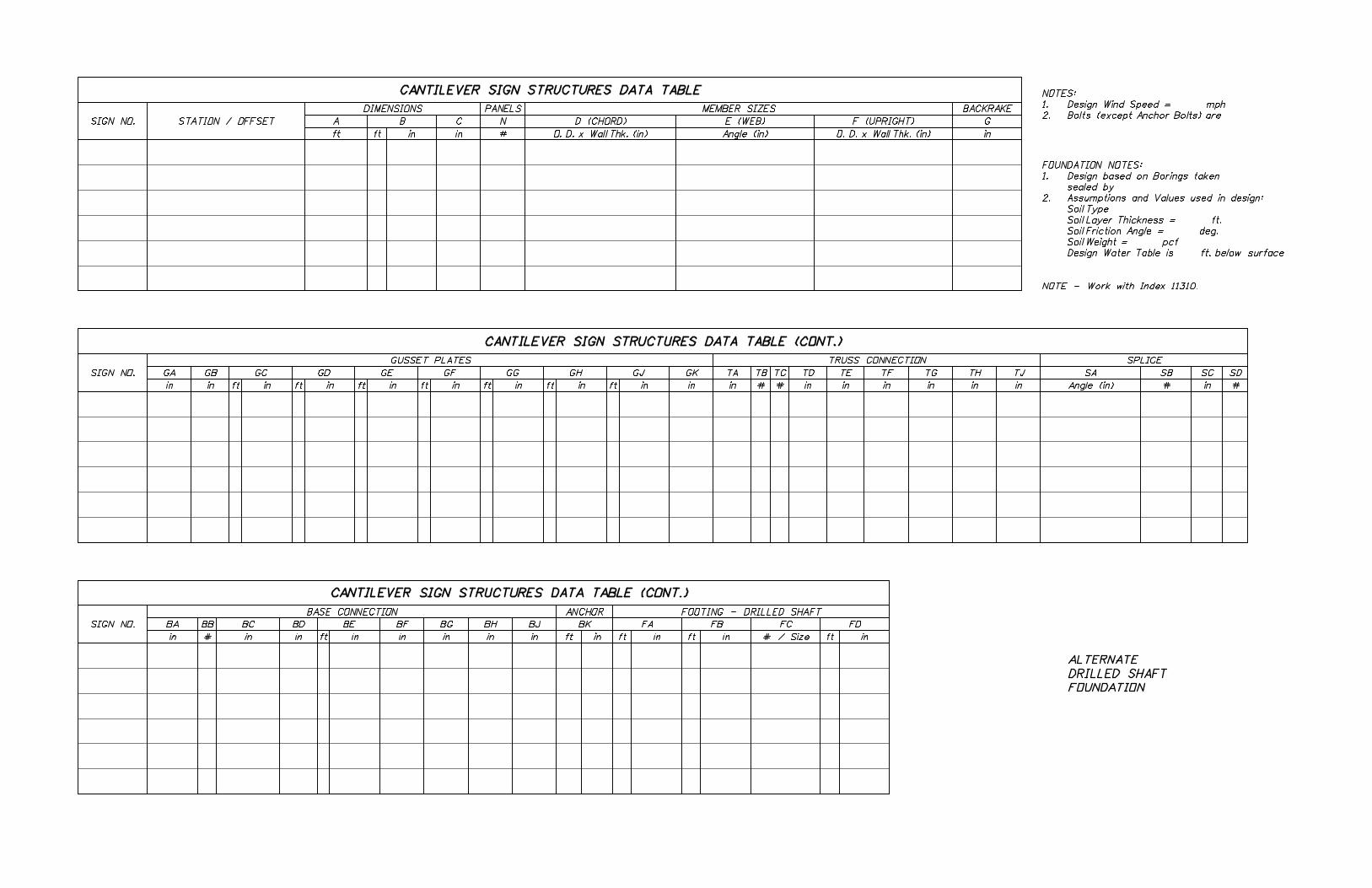
Cantilever Sign Structure Data Table
Span Sign Structure Data Table
Mast-arm Assemble Data Table (Standard)
Mast-arm Assemble Data Table (Special)
Prestressed Beam Temporary Bracing Data Tables
Florida-I Beam Table of Variables
Type II Beam Table of Variables
Type III Beam Table of Variables
Type IV Beam Table of Variables
Type V Beam Table of Variables
Type VI Beam Table of Variables
Bulb-T 72 Beam Table of Variables
Bulb-T 78 Beam Table of Variables
I-Beam Buildup and Deflection Data Table (AASHTO, Bulb-T & Florida-I Beams)
Florida-U Beam Table of Variables
Florida-U Beam Buildup and Deflection Data Table
Inverted-T Beam Table of Variables
Prestressed Custom Width Slab Units Table of Variables
Prestressed Standard Width Slab Units Table of Variables
Prestressed Slab Units - Traffic Railing Reinforcing Layout Table
Prestressed Slab Unit Overlay and Deflection Data Table
Concrete Sheet Pile Data Table
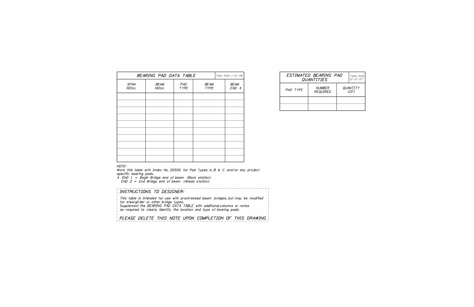
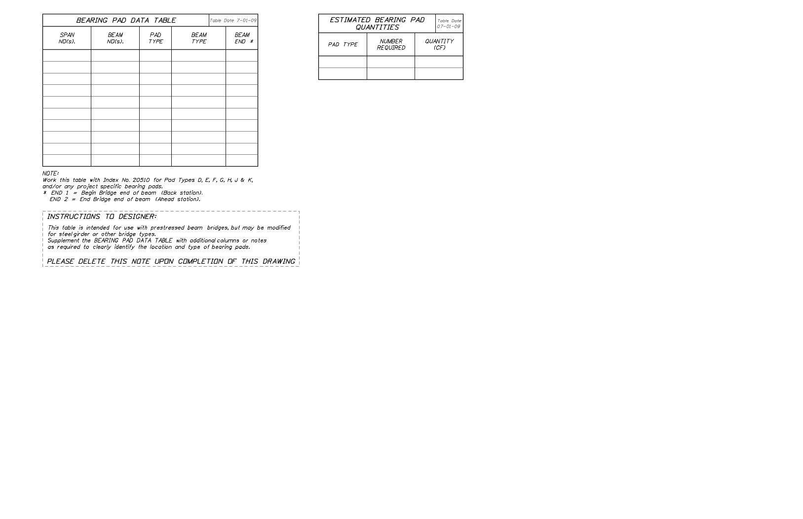
Bearing Pad Data Table (AASHTO and Bulb-T Beams)
Bearing Plate Data Table (AASHTO and Bulb-T Beams)
Bearing Pad Data Table (Florida-U Beams)
Bearing Pad Data Table (Florida-I Beams)
Bearing Plate Data Table (Florida-I Beams)
Bearing Plate Data Table (Florida-I Beams)
Pile Data Table
Approach Slab Table of Dimensions (Flexible)
Approach Slab Table of Dimensions (Rigid)
Strip Seal Expansion Joint Data Table
Poured Expansion Joint Data Table
Fender System Heavy Duty Data Tables
Fender System Medium Duty Data Tables
Fender System Light Duty Data Tables
289
5100
5200
5200
5200
5200
5200
5200
5200
5200
5200
5200
5200
5200
5200
5200
5200
5300
5301
11310
11320
17743
17745
20005
20010
20120
20130
20140
20150
20160
20172
20178
20199
20210
20299
20320
20350
20350
20350
20399
20400
20500
20501
20502
20510
20511
20512
20600
20900
20910
21100
21110
21910
21920
21930
00289
05100
05200
05200-BP1
05200-BP2
05200-BP3
05200-F1
05200-F2
05200-Grid
05200-LG1
05200-LG2
05200-LG3
05200-SB1
05200-SE1
05200-SE2
05200-WI1
05200-WI2
05300
05301
11310
11320
17743
17745
20005
20010
20120
20130
20140
20150
20160
20172
20178
20199
20210
20299
20320
20350a
20350b
20350c
20399
20400
20500
20501
20502
20510
20511
20512
20600
20900
20910
21100
21110
21910
21920
21930


TOTAL:
side of wall.
4. Front Face indicates roadway side of wall. Back Face indicates non-roadway
the above table and elsewhere in the plans.
3. Sound barriers shall meet the project aesthetic requirements as depicted in
www.dot.state.fl.us/specificationsoffice/
following web site address for the Qualified Products List for Sound Barrier Systems:
by the Engineer when all project aesthetic requirements can be met. Refer to the
QPL approved proprietary sound barrier systems not listed above may be approved
3). __________
2). __________
1). __________
sound barrier systems (panels and foundation):
2. The Contractor may also choose one of the following QPL approved proprietary
www.dot.state.fl.us/specificationsoffice/
following web site address for the Qualified Products List for Sound Barrier Panels:
by the Engineer when all project aesthetic requirements can be met. Refer to the
QPL approved proprietary sound barrier panels not listed above may be approved
3). __________
2). __________
1). __________
used with FDOT standard posts and foundations:
herein or one of the following QPL approved proprietary sound barrier panels
1. The Contractor may choose the Standard Precast 20’-0" Panel Option depicted
NOTES:
TOTAL:
(SF)
AREA
BOTH
BACK FACE/
FRONT FACE/
STATION TO STATIONNO.
WALL
Table Date 1-01-06LIMITS OF ANTI-GRAFFITI COATING
SOUND BARRIERS DATA TABLES
PROJECT AESTHETIC REQUIREMENTS Table Date 7-01-08
EITHER
PANEL/
RECESSED
PANEL/
FLUSH
POSTS:
FRONT FACE(4)
BACK FACE
REQUIRED TEXTURES (3):
FRONT FACE
PANELS:
(5)
POST CAP
PRECAST
(2)
COATINGS
COLORED
REQUIRED: (YES/NO)
(1)
GRAPHICS
WALL NOS:
(5) See Index 5207. Coat post caps the same color as posts, with a Class 5 Applied Finish Coating.
(4) Provide broom or Type "A" (smooth) finish when flush face panel option is utilized.
(3) See Index 5201.
The color shall be per Federal Color Chart, Federal Standard No. 595B, Table _____, Color _____.
(2) Coat all exposed faces of wall with (sacrificial/non-sacrificial) anti-graffiti coating or Class 5 Applied Finish Coating.
(1) See Control Drawings.
NO.
WALLSTATION TO STATION
SUMMARY OF FOUNDATIONS AND WALL QUANTITIES
(6)
FOUNDATION
(FT)
WALL ELEV.
TOP OF
(FT)
WALL ELEV.
BOTTOM OF
Table Date 07-01-10
(SF)
AREA
Granular Soils). See Plans for "SD" (Special Design) details.
(6) See Index No. 5206 for "1" (Table 1 - Medium Dense Granular Soils) and "2" (Table 2 - Loose


0


B
PRESTRESSED BEAM TEMPORARY BRACING DATA TABLES
TABLE OF WIND LOAD VARIABLES Table Date 1-01-10
WIND SPEED, CONSTRUCTION INACTIVE (MPH)
WIND SPEED, BASIC (MPH)
WIND SPEED, CONSTRUCTION ACTIVE (MPH)
VELOCITY PRESSURE EXPOSURE COEFFICIENT
GUST EFFECT FACTOR
LOADS (UNFACTORED)
TABLE OF ASSUMED CONSTRUCTION Table Date 1-01-10
BUILD-UP (PLF)
FORM WEIGHT (PSF)
FINISHING MACHINE TOTAL WEIGHT (KIP)
BEYOND EDGE OF DECK OVERHANG (IN.)
FINISHING MACHINE WHEEL LOCATION
DECK WEIGHT (PSF)
LIVE LOAD (PSF)
LIVE LOAD AT EXTREME DECK EDGE (PLF)
TABLE OF TEMPORARY BRACING VARIABLES
BRACE (KIP)
END AND ANCHOR
AT EACH BEAM
HORIZONTAL FORCE
LENGTH (FT)
UNBRACED
MAXIMUM
L ,
NO.
SPAN
BRACE (KIP)
INTERMEDIATE SPAN
FORCE AT EACH
HORIZONTAL
BRACE (KIPxFT)
END AND ANCHOR
FORCE AT EACH BEAM
OVERTURNING
BRACE (KIPxFT)
INTERMEDIATE SPAN
FORCE AT EACH
OVERTURNING
RELEASE?
TO CRANE
PRIOR
BRACE ENDS
Table Date 7-01-10
BRACING
OF
LINES
TOTAL
YES/NO
YES/NO
YES/NO
YES/NO
5. Horizontal and overturning forces are factored per the Strength III limit state for construction.
the exposure period is more than one year; for this case the Contractor shall re-calculate bracing requirements.
less than one year. Horizontal bracing forces, as specified in the ’TABLE OF TEMPORARY BRACING VARIABLES’, are not valid if
4. The exposure period (defined as the time period for which temporary load cases of the superstructure exist) is assumed to be
until diaphragm concrete or bridge deck concrete reaches 2500 psi.
TEMPORARY BRACING VARIABLES’. Beams shall not be left un-braced during non-work hours. Bracing shall remain in place
3. The temporary bracing at the ends of the beams shall be installed prior to crane release if indicated in the ’TABLE OF
the value listed.
loads exceed the assumed loads shown, or if the finishing machine wheel location from the edge of the deck overhang exceeds
CONSTRUCTION LOADS’. It is the Contractor’s responsibility to re-calculate the bracing requirements if the actual construction
Load as listed in the ’TABLE OF WIND LOAD VARIABLES’ plus the assumed construction loads shown in the ’TABLE OF ASSUMED
OF WIND LOAD VARIABLES’. The overturning brace forces have been determined by application of the Construction Active Wind
2. The horizontal brace forces have been determined by application of the Construction Inactive Wind Load as listed in the ’TABLE
centerline of the beam at the top of the top flange.
perpendicular to the beam web at mid-height of the beam, and assume that overturning bracing forces are applied at the
overturning forces given in the Table, non-simultaneously with horizontal forces. Assume that horizontal bracing forces are applied
in the ’TABLE OF TEMPORARY BRACING VARIABLES’. Also design bracing members and connections to be capable of resisting the
1. Design the bracing members and connections to transfer both compressive and tensile forces equal to the horizontal forces given
beam temporary bracing:
Design Standard Index No. 20005 is required. The Table and following information is provided to aid the Contractor in design of
Based on investigation of the beam stability, temporary bracing as shown in the ’TABLE OF TEMPORARY BRACING VARIABLES’ and
BEAM TEMPORARY BRACING NOTES:


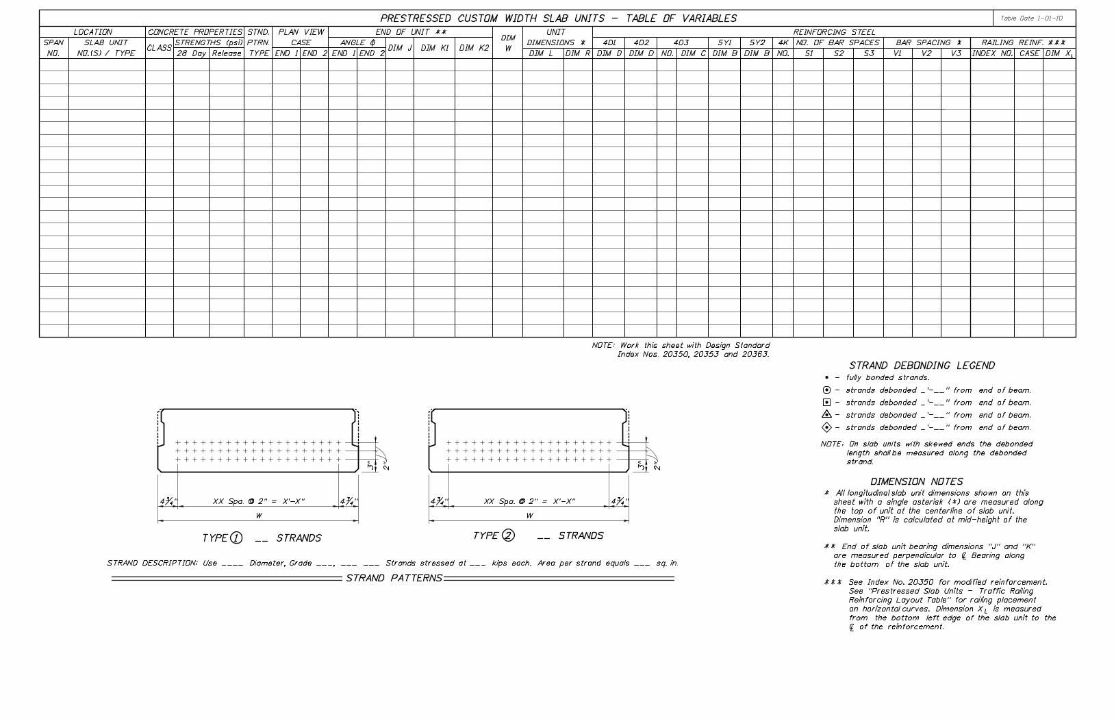
STRAND DEBONDING LEGEND
- strands debonded _’-__" from end of beam.
- strands debonded _’-__" from end of beam.
- strands debonded _’-__" from end of beam.
- strands debonded _’-__" from end of beam.
- fully bonded strands.
DIMENSION NOTES
TYPE 1 __ STRANDS TYPE 2 __ STRANDS
STRAND PATTERNS
STRAND DESCRIPTION: Use ____ Diameter, Grade ___, ___ ___ Strands stressed at ___ kips each. Area per strand equals ___ sq. in.
NOTE: On slab units with skewed ends the debonded
length shall be measured along the debonded
strand.
2"
3"
2"
3"
4�"4�" 4�" 4�"XX Spa. @ 2" = X’-X"
W
XX Spa. @ 2" = X’-X"
W
* All longitudinal slab unit dimensions shown on this
sheet with a single asterisk (*) are measured along
the top of unit at the centerline of slab unit.
Dimension "R" is calculated at mid-height of the
slab unit.
** End of slab unit bearing dimensions "J" and "K"
are measured perpendicular to | Bearing along
the bottom of the slab unit.
*** See Index No. 20350 for modified reinforcement.
See "Prestressed Slab Units - Traffic Railing
Reinforcing Layout Table" for railing placement
on horizontal curves. Dimension X is measured
from the bottom left edge of the slab unit to the
| of the reinforcement.
L
DIM
W
PRESTRESSED CUSTOM WIDTH SLAB UNITS - TABLE OF VARIABLES
NOTE: Work this sheet with Design Standard
Index Nos. 20350, 20353 and 20363.
Table Date 1-01-10
DIM L DIM R
REINFORCING STEEL
V3V2V1
UNIT
DIMENSIONS * 4K
NO. S1 S2 S3
NO. OF BAR SPACES
CASE L
RAILING REINF. ***
DIM XINDEX NO.DIM D DIM D
4D1 4D2CLASS
CONCRETE PROPERTIES
STRENGTHS (psi)
28 Day Release
STND.
PTRN.
TYPE
PLAN VIEW
CASE
END 1 END 2
ANGLE \
END 1 END 2DIM J DIM K1 DIM K2
LOCATION
SPAN
NO.
END OF UNIT **
SLAB UNIT
NO.(S) / TYPE NO.
4D3
DIM C
5Y1
DIM B
5Y2
DIM B
BAR SPACING *

STRAND DEBONDING LEGEND
- strands debonded _’-__" from end of beam.
- strands debonded _’-__" from end of beam.
- strands debonded _’-__" from end of beam.
- strands debonded _’-__" from end of beam.
- fully bonded strands.
DIMENSION NOTES
TYPE 1 __ STRANDS
TYPE 2 __ STRANDS
TYPE 3 __ STRANDS
TYPE 4 __ STRANDS
STRAND PATTERNS
STRAND DESCRIPTION: Use ____ Diameter, Grade ___, ___ ___ Strands stressed at ___ kips each. Area per strand equals ___ sq. in.
NOTE: On slab units with skewed ends the debonded
length shall be measured along the debonded
strand.
2"
3"
2"
3"
2"
3"
2"
3"
4’-11�"
25 Spa. @ 2" = 4’-2"4�" 4�"
4�" 4�"25 Spa. @ 2" = 4’-2"
4’-11�" 3’-11�"
19 Spa. @ 2" = 3’-2"
4�" 4�"19 Spa. @ 2" = 3’-2"
3’-11�"
4�" 4�"
* All longitudinal slab unit dimensions shown on this
sheet with a single asterisk (*) are measured along
the top of unit at the centerline of slab unit.
Dimension "R" is calculated at mid-height of the
slab unit.
** End of slab unit bearing dimensions "J" and "K"
are measured perpendicular to | Bearing along the
bottom of the slab unit.
*** See Index No. 20350 for modified reinforcement.
See "Prestressed Slab Units - Traffic Railing
Reinforcing Layout Table" for railing placement
on horizontal curves. Dimension "X " is measured
from the bottom left edge of slab unit to the
| reinforcement.
L
Table Date 1-01-10
DIM L DIM R
REINFORCING STEEL
V3V2V1
UNIT
DIMENSIONS * 4K
NO. S1 S2 S3
NO. OF BAR SPACES
CASE L
RAILING REINF. ***
DIM XINDEX NO.DIM D DIM BDIM D
4D1 4D2 4D3
DIM B
Y1 Y2
NO.CLASS
CONCRETE PROPERTIES
STRENGTHS (psi)
28 Day Release
STND.
PTRN.
TYPE
PLAN VIEW
CASE
END 1 END 2
ANGLE \
END 1 END 2DIM J DIM K1 DIM K2
LOCATION
SPAN
NO.
END OF UNIT **
SLAB UNIT
NO.(S) / TYPE
PRESTRESSED STANDARD SLAB UNITS - TABLE OF VARIABLES
BAR SPACING *
NOTE: Work this sheet with Design Standards Index
Nos. 20350, 20354, 20355, 20364 and 20365.


D
D

D
D
D


D
D

(inches)
BEVELED PLATE DIMENSIONS (PLATE B)
Table Date 7-01-10
X Y ZWFEDC(Yes/No)
REQUIRED
PLATE
BEVELED
F
(inches)
DIMENSIONS (PLATE A)
EMBEDDED PLATE
BEARING PLATE DATA TABLE
Gˆ *
ANGLE
(%) **
SLOPE
CASE
VIEW
PLAN
END
BEAM
TYPE
PAD
GENERAL BEARING PLATE DATA
NO(s).
BEAM
NO(s).
SPAN
MARK ***
BRG. PLATE
See Index No. 20512 for additional notes and details.
*** See "TABLE OF BEAM VARIABLES" and Index No. 20010.
** Slope measured along ´ of Beam at ´ of Bearing.
* ˆ = Acute angle ( = 90°) measured from left or right side of ´ Beam as required.
NOTES:
90°
(End 2)
Beam End
F
Y
D
Z´ Bearing
E
END 2
PLATE B
W
*̂
*̂
90°C
E
X
90°
D
´ Plate
´ Beam &
F
X
screws (Typ.)
dia. countersunk
"43Holes for
E
90°C
*̂
*̂
F
(End 1)
Beam Endˆ*
90°Skew Angle
ˆ*
Skew Angle90° or ´ Pier or Bent
Front Face of Backwall
END 1 P
LATE B
Z
´ Bearing W
E
Dire
ction
of Statio
ning
(SKEWED PLATES SHOWN, NON-SKEWED PLATES SIMILAR)
ISOMETRIC VIEW OF BEVELED BEARING PLATES FOR FLORIDA I-BEAMS
F
Z = 0.5"
Y = 0.5" - (D/tan ˆ) x Slope
X = 0.5" - (C/sin ˆ + D/tan ˆ) x Slope
W = 0.5" - (C/sin ˆ) x Slope
Z = 0.5" + (C/sin ˆ + D/tan ˆ) x Slope
Y = 0.5" + (C/sin ˆ) x Slope
X = 0.5"
W = 0.5" + (D/tan ˆ) x Slope
Y = Z = 0.5"
W = X = 0.5" - (C) x Slope
Y = Z = 0.5" + (C) x Slope
W = X = 0.5"
Z = 0.5" - (D/tan ˆ) x Slope
Y = 0.5"
X = 0.5" - (C/sin ˆ) x Slope
W = 0.5" - (C/sin ˆ + D/tan ˆ) x Slope
Z = 0.5" + (C/sin ˆ) x Slope
Y = 0.5" + (C/sin ˆ + D/tan ˆ) x Slope
X = 0.5" + (D/tan ˆ) x Slope
W = 0.5"
PLEASE DELETE THIS NOTE UPON COMPLETION OF THIS DRAWING
INSTRUCTIONS TO DESIGNER:
Y
Z = 0.5" - (C/sin ˆ + D/tan ˆ) x Slope
Y = 0.5" - (C/sin ˆ) x Slope
X = 0.5"
W = 0.5" - (D/tan ˆ) x Slope
(b) END ELEVATION CONDITION 1 or 3 (Negative Slope)
Z = 0.5"
Y = 0.5" + (D/tan ˆ) x Slope
X = 0.5" + (C/sin ˆ + D/tan ˆ) x Slope
W = 0.5" + (C/sin ˆ) x Slope
(a) END ELEVATION CONDITION 1 or 2 (Positive Slope)
(III) PLAN VIEW CASE 3:
Z = 0.5" - (C/sin ˆ) x Slope
Y = 0.5" - (C/sin ˆ + D/tan ˆ) x Slope
X = 0.5" - (D/tan ˆ) x Slope
W = 0.5"
(b) END ELEVATION CONDITION 1 or 3 (Negative Slope)
Z = 0.5" + (D/tan ˆ) x Slope
Y = 0.5"
X = 0.5" + (C/sin ˆ) x Slope
W = 0.5" + (C/sin ˆ + D/tan ˆ) x Slope
(a) END ELEVATION CONDITION 1 or 2 (Positive Slope)
(II) PLAN VIEW CASE 2:
Y = Z = 0.5" - (C) x Slope
W = X = 0.5"
(b) END ELEVATION CONDITION 1 or 3 (Negative Slope)
Y = Z = 0.5"
W = X = 0.5" + (C) x Slope
(a) END ELEVATION CONDITION 1 or 2 (Positive Slope)
(I) PLAN VIEW CASE 1:
END 1 END 2
F = D/sin ˆ
E = C/sin ˆ For Bearing Pad Type D-K, G = 13�"/sin ˆ
3. For all cases and either end:
The Slope parameter in these equations requires decimal units and correct sign convention:
and ’END ELEVATION CONDITIONS’ corresponding to those shown on Design Standards Index No. 20010.
2. Use the following equations to determine the Beveled Plate thicknesses for ’PLAN VIEW CASES’
Beveled Plate dimensions ’W’, ’X’, ’Y’ & ’Z’ rounded to �th of an inch.
1. Fill in the table to correspond with data on the ’TABLE OF BEAM VARIABLES’ using inch units for

for projects without Test Piles
INSTRUCTION TO DESIGNER: Change to "PILE ORDER LENGTH (ft.)"
PILE DATA TABLE
DESIGN CRITERIAINSTALLATION CRITERIA
NUMBER
BENT
or
PIER
(in.)
SIZE
PILE
(tons)
RESISTANCE
BEARING
NOMINAL
(tons)
RESISTANCE
TENSION
(ft.)
ELEVATION
TIP
MINIMUM
(ft.)
LENGTH
PILE
TEST
(ft.)
ELEVATION
JET
REQUIRED
(ft.)
ELEVATION
PREFORM
REQUIRED
(tons)
LOAD
DESIGN
FACTORED
(tons)
DRAG
DOWN
(tons)
RESISTANCE
SCOUR
TOTAL
(tons)
RESISTANCE
SCOUR
NET
(ft.)
ELEVATION
SCOUR
100-YEAR
EL
EV
ATIO
N (ft.)
SC
OU
R
LO
NG
TE
RM
PILE 1 PILE 2 PILE 3 PILE 4 PILE 5
PILE CUT-OFF ELEVATIONS
PILE 6 PILE 7 PILE 8 PILE 9
Table Date 7-01-10
FA
CT
OR-ˆ
RE
SIS
TA
NC
E
DO NOT INCLUDE THIS "INSTRUCTIONS TO DESIGNER" NOTE IN PLANS
instrumentation.
number of piles, piers and/or bents, use of Test Piles and EDC
Modify table and notes as required to accommodate the required
INSTRUCTIONS TO DESIGNER:
piles in accordance with Design Standard Index No. 20602.
Provide Embedded Data Collector (EDC) Instrumentation in all
EMBEDDED DATA COLLECTOR NOTE:
and proceed outward.
At each Bent, pile driving is to commence at the center of the Bent
whichever is deeper.
below the 100-year scour elevation or required jet elevation,
The Contractor should not anticipate being allowed to jet piles
No jetting will be allowed without the approval of the Engineer.
for determination of the required driving resistance.
differ from those shown on the table, the Engineer shall be responsible
until the pile driving is completed. If jetting or preforming elevations
lowered to the elevation and continue to operate at this elevation
When a required jetting elevation is shown, the jet shall be
Minimum Tip Elevation is required for lateral stability.
Contractor to verify location of all utilities prior to any pile driving.
PILE INSTALLATION NOTES:˜ Nominal Bearing Resistance
extreme event loading.
LONG TERM SCOUR ELEVATION - Estimated elevation of scour used in design for
storm event.
100-YEAR SCOUR ELEVATION - Estimated elevation of scour due to the 100 year
to the scour elevation.
required preformed or jetting elevation
resistance provided by the soil from the
NET SCOUR RESISTANCE - An estimate of the ultimate static side friction
resistance provided by the scourable soil.
TOTAL SCOUR RESISTANCE - An estimate of the ultimate static side friction
(Specify only when design requires tension capacity).
the 100 year scour elevation to resist pullout of the pile
TENSION RESISTANCE - The ultimate side friction capacity that must be obtained below
Factored Design Load + Net Scour Resistance + Down Drag
ˆ