Embed Size (px)
Citation preview

Skyworks Solutions, Inc. • Phone [781] 376-3000 • Fax [781] 376-3100 • [email protected] • www.skyworksinc.com 202414I • Skyworks Proprietary Information • Products and Product Information are Subject to Change Without Notice • November 19, 2015 1
DATA SHEET
SE2438T: 2.4 GHz ZigBee®/Smart Energy Front-End Module Applications Smart meters
In-home appliances
Smart thermostats
Features Integrated:
– PA with up to +16 dBm output power – LNA with programmable bypass – Transmit and receive switching function
+2.7 dB FEM Rx NF
Differential Rx/Tx interface with integrated balun
Fast switch on/off time <800 ns
2.0 V to 3.6 V supply operation
Sleep mode current 0.05 μA typical
QFN (20-pin, 3.0 mm x 3.0 mm x 0.55 mm) package (MSL1 @ 260 °C per JEDEC J-STD-020)
Skyworks GreenTM products are compliant withall applicable legislation and are halogen-free.For additional information, refer to SkyworksDefinition of GreenTM, document number SQ04–0074.
VCC1
VB_IN
TRXP
TRXN
GND
DNC
GND
ANT
CSD
CTX
VCC
N/C
CPS
GND
CRX
GND
VCC2
GND
N/C
N/C
1
2
3
4
5
15
14
13
12
11
6 7 8 9 10
20 19 18 17 16
Y0770
Figure 2. SE2438T Pinout—20-Pin QFN (Top View)
VB_IN
Balun
CRX
CSD
CTX
Logic Control
ANT
PA
LNA
CPS
TRXPTRXN
Y1854
Figure 1. SE2438T Block Diagram
Description The SE2438T is a high-performance, fully integrated RF front-end module (FEM) that is designed for ZigBee®/Smart Energy applications.
The SE2438T is designed for ease of use and maximum flexibility, with integrated fully matched input balun, integrated inter-stage matching and harmonic filter, and digital controls that are compatible with 1.6 V to 3.6 V Complementary Metal Oxide Semiconductor (CMOS) levels.
The RF blocks operate over a wide supply voltage range from 2.0 V to 3.6V, which allows the SE2438T to be used in battery-powered applications over a wide spectrum of the battery discharge curve.
A functional block diagram is shown in Figure 1. The pin configuration and package are shown in Figure 2. Signal pin assignments and functional pin descriptions are provided in Table 1.
DATA SHEET • SE2438T: 2.4 GHz SMART ENERGY/ZIGBEE FRONT-END MODULE
Skyworks Solutions, Inc. • Phone [781] 376-3000 • Fax [781] 376-3100 • [email protected] • www.skyworksinc.com 2 November 19, 2015 • Skyworks Proprietary Information • Products and Product Information are Subject to Change Without Notice • 202414I
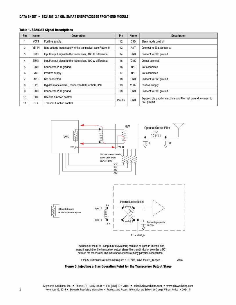
Table 1. SE2438T Signal Descriptions
Pin Name Description Pin Name Description
1 VCC1 Positive supply 12 CSD Sleep mode control
2 VB_IN Bias voltage input supply to the transceiver (see Figure 3) 13 ANT Connect to 50 Ω antenna
3 TRXP Input/output signal to the transceiver, 100 Ω differential 14 GND Connect to PCB ground
4 TRXN Input/output signal to the transceiver, 100 Ω differential 15 DNC Do not connect
5 GND Connect to PCB ground 16 N/C Not connected
6 VCC Positive supply 17 N/C Not connected
7 N/C Not connected 18 GND Connect to PCB ground
8 CPS Bypass mode control, connect to RFIC or SoC GPIO 19 VCC2 Positive supply
9 GND Connect to PCB ground 20 GND Connect to PCB ground
10 CRX Receive function control Paddle GND
Exposed die paddle; electrical and thermal ground; connect to PCB ground 11 CTX Transmit function control
The balun at the FEM PA input (or LNA output) can also be used to inject a biasoperating point for the transceiver output stage (the shunt inductor provides a DC
path on the other side). The inductor also tunes out any parasitic capacitance.
If the SOIC transceiver does not require a DC bias, leave the VB_IN open.
CPSCSDCTXCRX
FEM
SoIC
VDD_PA VB_IN
1 pF 1 pF
2n7
1 kΩ each series resistor,placed close to the SE2438T pins.
Optional Output Filter
Y1855
Differential sourceor load impedance symbol
Input
Input
1.8 V VBIAS_IN
1.8 V
1.8 V Decoupling capacitoron chip
Internal Lattice Balun
Figure 3. Injecting a Bias Operating Point for the Transceiver Output Stage
DATA SHEET • SE2438T: 2.4 GHz SMART ENERGY/ZIGBEE FRONT-END MODULE
Skyworks Solutions, Inc. • Phone [781] 376-3000 • Fax [781] 376-3100 • [email protected] • www.skyworksinc.com 202414I • Skyworks Proprietary Information • Products and Product Information are Subject to Change Without Notice • November 19, 2015 3
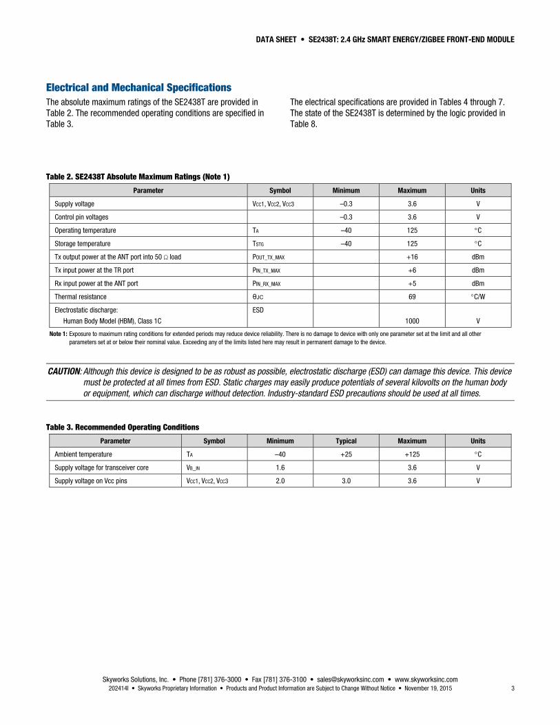
Electrical and Mechanical Specifications The absolute maximum ratings of the SE2438T are provided in Table 2. The recommended operating conditions are specified in Table 3.
The electrical specifications are provided in Tables 4 through 7. The state of the SE2438T is determined by the logic provided in Table 8.
Table 2. SE2438T Absolute Maximum Ratings (Note 1)
Parameter Symbol Minimum Maximum Units
Supply voltage VCC1, VCC2, VCC3 –0.3 3.6 V
Control pin voltages –0.3 3.6 V
Operating temperature TA –40 125 C
Storage temperature TSTG –40 125 C
Tx output power at the ANT port into 50 Ω load POUT_TX_MAX +16 dBm
Tx input power at the TR port PIN_TX_MAX +6 dBm
Rx input power at the ANT port PIN_RX_MAX +5 dBm
Thermal resistance θJC 69 C/W
Electrostatic discharge:
Human Body Model (HBM), Class 1C
ESD
1000
V
Note 1: Exposure to maximum rating conditions for extended periods may reduce device reliability. There is no damage to device with only one parameter set at the limit and all other parameters set at or below their nominal value. Exceeding any of the limits listed here may result in permanent damage to the device.
CAUTION: Although this device is designed to be as robust as possible, electrostatic discharge (ESD) can damage this device. This device must be protected at all times from ESD. Static charges may easily produce potentials of several kilovolts on the human body or equipment, which can discharge without detection. Industry-standard ESD precautions should be used at all times.
Table 3. Recommended Operating Conditions
Parameter Symbol Minimum Typical Maximum Units
Ambient temperature TA –40 +25 +125 C
Supply voltage for transceiver core VB_IN 1.6 3.6 V
Supply voltage on Vcc pins VCC1, VCC2, VCC3 2.0 3.0 3.6 V
DATA SHEET • SE2438T: 2.4 GHz SMART ENERGY/ZIGBEE FRONT-END MODULE
Skyworks Solutions, Inc. • Phone [781] 376-3000 • Fax [781] 376-3100 • [email protected] • www.skyworksinc.com 4 November 19, 2015 • Skyworks Proprietary Information • Products and Product Information are Subject to Change Without Notice • 202414I
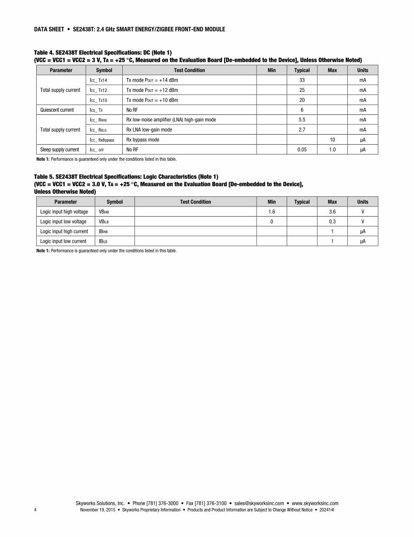
Table 4. SE2438T Electrical Specifications: DC (Note 1) (VCC = VCC1 = VCC2 = 3 V, TA = +25 C, Measured on the Evaluation Board [De-embedded to the Device], Unless Otherwise Noted)
Parameter Symbol Test Condition Min Typical Max Units
Total supply current
ICC_ TX14 Tx mode POUT = +14 dBm 33 mA
ICC_ TX12 Tx mode POUT = +12 dBm 25 mA
ICC_ TX10 Tx mode POUT = +10 dBm 20 mA
Quiescent current ICQ_ TX No RF 6 mA
Total supply current
ICC_ RXHG Rx low-noise amplifier (LNA) high-gain mode 5.5 mA
ICC_ RXLG Rx LNA low-gain mode 2.7 mA
ICC_ RxBypass Rx bypass mode 10 μA
Sleep supply current ICC_ OFF No RF 0.05 1.0 μA
Note 1: Performance is guaranteed only under the conditions listed in this table.
Table 5. SE2438T Electrical Specifications: Logic Characteristics (Note 1) (VCC = VCC1 = VCC2 = 3.0 V, TA = +25 C, Measured on the Evaluation Board [De-embedded to the Device], Unless Otherwise Noted)
Parameter Symbol Test Condition Min Typical Max Units
Logic input high voltage VBIHB 1.6 3.6 V
Logic input low voltage VBILB 0 0.3 V
Logic input high current IBIHB 1 μA
Logic input low current IBILB 1 μA
Note 1: Performance is guaranteed only under the conditions listed in this table.
DATA SHEET • SE2438T: 2.4 GHz SMART ENERGY/ZIGBEE FRONT-END MODULE
Skyworks Solutions, Inc. • Phone [781] 376-3000 • Fax [781] 376-3100 • [email protected] • www.skyworksinc.com 202414I • Skyworks Proprietary Information • Products and Product Information are Subject to Change Without Notice • November 19, 2015 5
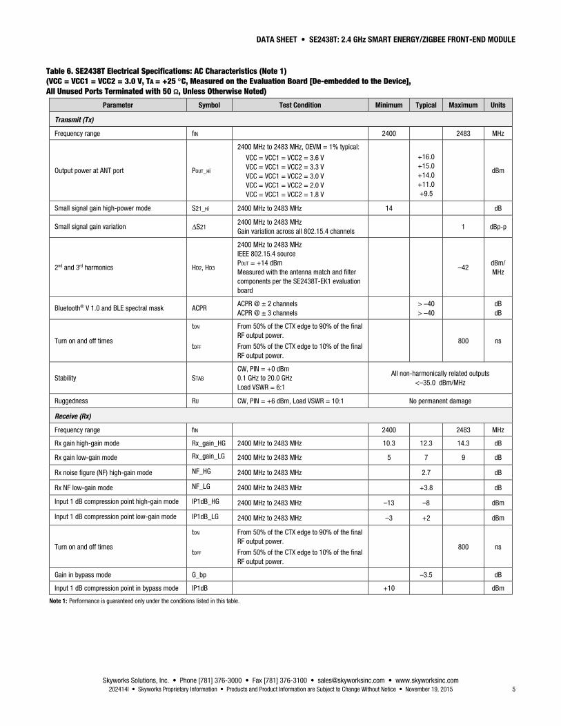
Table 6. SE2438T Electrical Specifications: AC Characteristics (Note 1) (VCC = VCC1 = VCC2 = 3.0 V, TA = +25 C, Measured on the Evaluation Board [De-embedded to the Device], All Unused Ports Terminated with 50 Ω, Unless Otherwise Noted)
Parameter Symbol Test Condition Minimum Typical Maximum Units
Transmit (Tx)
Frequency range fIN 2400 2483 MHz
Output power at ANT port POUT_Hi
2400 MHz to 2483 MHz, OEVM = 1% typical:
VCC = VCC1 = VCC2 = 3.6 V VCC = VCC1 = VCC2 = 3.3 V VCC = VCC1 = VCC2 = 3.0 V VCC = VCC1 = VCC2 = 2.0 V VCC = VCC1 = VCC2 = 1.8 V
+16.0 +15.0 +14.0 +11.0 +9.5
dBm
Small signal gain high-power mode S21_Hi 2400 MHz to 2483 MHz 14 dB
Small signal gain variation ΔS21 2400 MHz to 2483 MHz Gain variation across all 802.15.4 channels
1 dBp-p
2nd and 3rd harmonics HD2, HD3
2400 MHz to 2483 MHz IEEE 802.15.4 source POUT = +14 dBm Measured with the antenna match and filter components per the SE2438T-EK1 evaluation board
–42 dBm/MHz
Bluetooth® V 1.0 and BLE spectral mask ACPR ACPR @ ± 2 channels ACPR @ ± 3 channels
> –40 > –40
dB dB
Turn on and off times
tON
tOFF
From 50% of the CTX edge to 90% of the final RF output power.
From 50% of the CTX edge to 10% of the final RF output power.
800 ns
Stability STAB CW, PIN = +0 dBm 0.1 GHz to 20.0 GHz Load VSWR = 6:1
All non-harmonically related outputs <–35.0 dBm/MHz
Ruggedness RU CW, PIN = +6 dBm, Load VSWR = 10:1 No permanent damage
Receive (Rx)
Frequency range fIN 2400 2483 MHz
Rx gain high-gain mode Rx_gain_HG 2400 MHz to 2483 MHz 10.3 12.3 14.3 dB
Rx gain low-gain mode Rx_gain_LG 2400 MHz to 2483 MHz 5 7 9 dB
Rx noise figure (NF) high-gain mode NF_HG 2400 MHz to 2483 MHz 2.7 dB
Rx NF low-gain mode NF_LG 2400 MHz to 2483 MHz +3.8 dB
Input 1 dB compression point high-gain mode IP1dB_HG 2400 MHz to 2483 MHz –13 –8 dBm
Input 1 dB compression point low-gain mode IP1dB_LG 2400 MHz to 2483 MHz –3 +2 dBm
Turn on and off times
tON
tOFF
From 50% of the CTX edge to 90% of the final RF output power.
From 50% of the CTX edge to 10% of the final RF output power.
800 ns
Gain in bypass mode G_bp –3.5 dB
Input 1 dB compression point in bypass mode IP1dB +10 dBm
Note 1: Performance is guaranteed only under the conditions listed in this table.
DATA SHEET • SE2438T: 2.4 GHz SMART ENERGY/ZIGBEE FRONT-END MODULE
Skyworks Solutions, Inc. • Phone [781] 376-3000 • Fax [781] 376-3100 • [email protected] • www.skyworksinc.com 6 November 19, 2015 • Skyworks Proprietary Information • Products and Product Information are Subject to Change Without Notice • 202414I
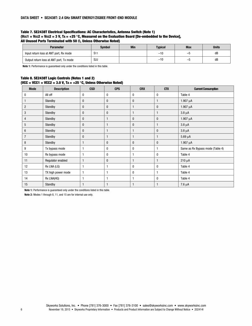
Table 7. SE2438T Electrical Specifications: AC Characteristics, Antenna Switch (Note 1) (VCC1 = VCC2 = VCC2 = 3 V, TA = +25 C, Measured on the Evaluation Board [De-embedded to the Device], All Unused Ports Terminated with 50 Ω, Unless Otherwise Noted)
Parameter Symbol Min Typical Max Units
Input return loss at ANT port, Rx mode S11 –10 –5 dB
Output return loss at ANT port, Tx mode S22 –10 –5 dB
Note 1: Performance is guaranteed only under the conditions listed in this table.
Table 8. SE2438T Logic Controls (Notes 1 and 2) (VCC = VCC1 = VCC2 = 3.0 V, TA = +25 C, Unless Otherwise Noted)
Mode Description CSD CPS CRX CTX Current Consumption
0 All off 0 0 0 0 Table 4
1 Standby 0 0 0 1 1.907 μA
2 Standby 0 0 1 0 1.907 μA
3 Standby 0 0 1 1 3.8 μA
4 Standby 0 1 0 0 1.907 μA
5 Standby 0 1 0 1 3.8 μA
6 Standby 0 1 1 0 3.8 μA
7 Standby 0 1 1 1 5.69 μA
8 Standby 1 0 0 0 1.907 μA
9 Tx bypass mode 1 0 0 1 Same as Rx Bypass mode (Table 4)
10 Rx bypass mode 1 0 1 0 Table 4
11 Regulator enabled 1 0 1 1 210 μA
12 Rx LNA (LG) 1 1 0 0 Table 4
13 TX high power mode 1 1 0 1 Table 4
14 Rx LNA(HG) 1 1 1 0 Table 4
15 Standby 1 1 1 1 7.6 μA
Note 1: Performance is guaranteed only under the conditions listed in this table.
Note 2: Modes 1 through 8, 11, and 15 are for internal use only.
DATA SHEET • SE2438T: 2.4 GHz SMART ENERGY/ZIGBEE FRONT-END MODULE
Skyworks Solutions, Inc. • Phone [781] 376-3000 • Fax [781] 376-3100 • [email protected] • www.skyworksinc.com 202414I • Skyworks Proprietary Information • Products and Product Information are Subject to Change Without Notice • November 19, 2015 7
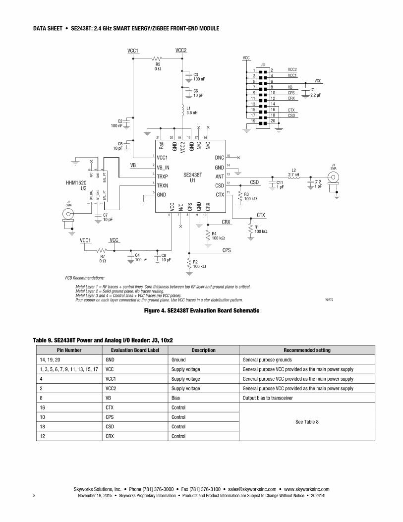
Evaluation Board Description The SE2438T Evaluation Board is used to test the performance of the SE2438T FEM. The board is optimized for evaluation, experimentation, and investigation with an 802.15.4 signal source. The design and layout can be quickly and easily transferred into a production design.
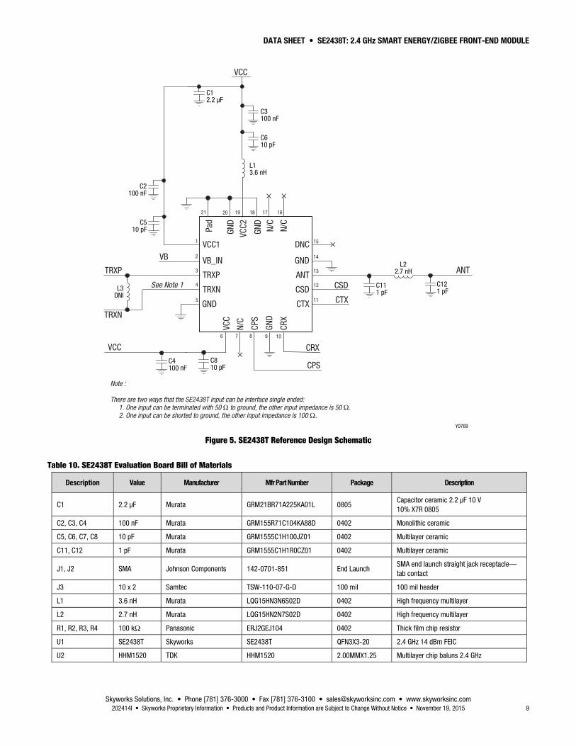
An Evaluation Board schematic diagram is provided in Figure 4. A reference design schematic is provided in Figure 5. Table 9 describes the pins on the power and control I/O header (J3). Table 10 provides the Bill of Materials (BOM) list for Evaluation Board components. A photograph of the Evaluation Board is shown in Figure 6.
Evaluation Board Setup Procedure
1. Connect (J1, J2) to 50 Ω instruments. Terminate all unused ports (if applicable) with 50 Ω.
2. Connect the supply ground to pin 19 or 20 of J3.
3. Connect 3.0 V to VCC, VCC1, and VCC2 of J3.
4. Connect 1.8 V to pin 8 of J3.
5. Monitor the 2.5 GHz amplifier transmit performance by applying an RF signal to J2 and monitoring the output power on J1 (ANT).
6. Monitor the 2.5 GHz amplifier receive performance by applying an RF signal to connector J1 (ANT) and monitoring the output signal on connector J2.
CAUTION: Care should be taken not to overdrive the amplifier by applying too much RF on the input to the device. A suitable starting input power would be –20 dBm.
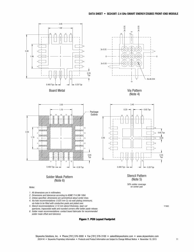
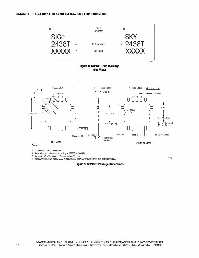
Package Dimensions The PCB layout footprint for the SE2438T is provided in Figure 7. Typical part markings for the SE2438T are shown in Figure 8. Package dimensions are shown in Figure 9, and tape and reel dimensions are provided in Figure 10.
Package and Handling Information Instructions on the shipping container label regarding exposure to moisture after the container seal is broken must be followed. Otherwise, problems related to moisture absorption may occur when the part is subjected to high temperature during solder assembly.
The SE2438T package is Pb free, RoHS compliant, halogen free, and rated to Moisture Sensitivity Level 1 (MSL1). For additional information, refer to the Skyworks Application Note, Solder Reflow Information, document number 200164.
Care must be taken when attaching this product, whether it is done manually or in a production solder reflow environment. Production quantities of this product are shipped in a standard tape and reel format.
DATA SHEET • SE2438T: 2.4 GHz SMART ENERGY/ZIGBEE FRONT-END MODULE
Skyworks Solutions, Inc. • Phone [781] 376-3000 • Fax [781] 376-3100 • [email protected] • www.skyworksinc.com 8 November 19, 2015 • Skyworks Proprietary Information • Products and Product Information are Subject to Change Without Notice • 202414I
Y0772
1 VCC1
TRXP
VB_IN
GND
N/C
CPS
GND
CRX
GND
VCC2
GND
N/C
N/C
TRXN
DNC
ANT
GND
CTX
CSD
2
3
4
5
14
15
13
12
11
6 7 8 9 10
20 19 18 17 16
×
C3100 nF
C610 pF
C510 pF
C121 pF
L22.7 nH
VB
C2100 nF
Pad
21
× ×
×
CTX
CSD C111 pF
CRX
CPSC810 pF
C4100 nF
VCC
VCC2
L13.6 nH
VCC
13579
1113151719
J3
VBCPSCRX
CTXCSD
2468101214161820
C12.2 μF
VCCVCC1
VCC
J1SMA
R3100 kΩ
R1100 kΩ
R2100 kΩ
R4100 kΩ
1 2 3
6 5 4
UN_B
AL
RF_G
ND
BAL_
PT
N/C
GND
BAL_
PT
×
C710 pF
J2SMA
HHM1520U2
SE2438TU1
PCB Recommendations:
Metal Layer 1 = RF traces + control lines. Core thickness between top RF layer and ground plane is critical. Metal Layer 2 = Solid ground plane. No traces routing. Metal Layer 3 and 4 = Control lines + VCC traces (no VCC plane). Pour copper on each layer connected to the ground plane. Use VCC traces in a star distribution pattern.
VCC2
VCC1
R50 Ω
R70 Ω
VCC1
Figure 4. SE2438T Evaluation Board Schematic
Table 9. SE2438T Power and Analog I/O Header: J3, 10x2
Pin Number Evaluation Board Label Description Recommended setting
14, 19, 20 GND Ground General purpose grounds
1, 3, 5, 6, 7, 9, 11, 13, 15, 17 VCC Supply voltage General purpose VCC provided as the main power supply
4 VCC1 Supply voltage General purpose VCC provided as the main power supply
2 VCC2 Supply voltage General purpose VCC provided as the main power supply
8 VB Bias Output bias to transceiver
16 CTX Control
See Table 8 10 CPS Control
18 CSD Control
12 CRX Control
DATA SHEET • SE2438T: 2.4 GHz SMART ENERGY/ZIGBEE FRONT-END MODULE
Skyworks Solutions, Inc. • Phone [781] 376-3000 • Fax [781] 376-3100 • [email protected] • www.skyworksinc.com 202414I • Skyworks Proprietary Information • Products and Product Information are Subject to Change Without Notice • November 19, 2015 9
Y0769
1 VCC1
TRXP
VB_IN
GND
N/C
CPS
GND
CRX
GND
VCC2
GND
N/C
N/C
TRXN
DNC
ANT
GND
CTX
CSD
2
3
4
5
14
15
13
12
11
6 7 8 9 10
20 19 18 17 16
×
C3100 nF
C610 pF
C510 pF
C121 pF
L22.7 nH
VB
C2100 nF
Pad
21
× ×
×
CTX
CSD
ANT
C111 pF
CRX
CPSC810 pF
C4100 nF
VCC
VCC
L13.6 nH
C12.2 μF
TRXP
L3DNI
TRXN
VCC
See Note 1
Note :
There are two ways that the SE2438T input can be interface single ended: 1. One input can be terminated with 50 Ω to ground, the other input impedance is 50 Ω. 2. One input can be shorted to ground, the other input impedance is 100 Ω.
Figure 5. SE2438T Reference Design Schematic
Table 10. SE2438T Evaluation Board Bill of Materials
Description Value Manufacturer Mfr Part Number Package Description
C1 2.2 μF Murata GRM21BR71A225KA01L 0805 Capacitor ceramic 2.2 μF 10 V 10% X7R 0805
C2, C3, C4 100 nF Murata GRM155R71C104KA88D 0402 Monolithic ceramic
C5, C6, C7, C8 10 pF Murata GRM1555C1H100JZ01 0402 Multilayer ceramic
C11, C12 1 pF Murata GRM1555C1H1R0CZ01 0402 Multilayer ceramic
J1, J2 SMA Johnson Components 142-0701-851 End Launch SMA end launch straight jack receptacle—tab contact
J3 10 x 2 Samtec TSW-110-07-G-D 100 mil 100 mil header
L1 3.6 nH Murata LQG15HN3N6S02D 0402 High frequency multilayer
L2 2.7 nH Murata LQG15HN2N7S02D 0402 High frequency multilayer
R1, R2, R3, R4 100 kΩ Panasonic ERJ2GEJ104 0402 Thick film chip resistor
U1 SE2438T Skyworks SE2438T QFN3X3-20 2.4 GHz 14 dBm FEIC
U2 HHM1520 TDK HHM1520 2.00MMX1.25 Multilayer chip baluns 2.4 GHz

DATA SHEET • SE2438T: 2.4 GHz SMART ENERGY/ZIGBEE FRONT-END MODULE
Skyworks Solutions, Inc. • Phone [781] 376-3000 • Fax [781] 376-3100 • [email protected] • www.skyworksinc.com 10 November 19, 2015 • Skyworks Proprietary Information • Products and Product Information are Subject to Change Without Notice • 202414I
Y0771
Figure 6. SE2438T Evaluation Board Photograph
DATA SHEET • SE2438T: 2.4 GHz SMART ENERGY/ZIGBEE FRONT-END MODULE
Skyworks Solutions, Inc. • Phone [781] 376-3000 • Fax [781] 376-3100 • [email protected] • www.skyworksinc.com 202414I • Skyworks Proprietary Information • Products and Product Information are Subject to Change Without Notice • November 19, 2015 11
Board Metal
Solder Mask Pattern(Note 6)
Stencil Pattern(Note 5)
Notes:
1. All dimensions are in millimeters.2. Dimensions and tolerances according to ASME Y14.5M-1994.3. Unless specified, dimensions are symmetrical about center lines.4. Via hole recommendations: 0.025 mm Cu via wall plating (minimum), via holes to be filled with conductive paste and plated over.5. Stencil recommendations: 0.10 mm stencil thickness, laser cut apertures, trapezoidal walls and rounded corners offer better paste release.6. Solder mask recommendations: contact board fabricator for recommended solder mask offset and tolerance.
3.40
0.400 Typ 0.20 Typ
3.40
58% solder coverageon center pad
PackageOutline
0.55Typ
1.90
1.70
3.50
9x Ø0.254
3.40
3x 0.55
Via Pattern(Note 4)
0.400 Typ
1.90
1.70
3.50
0.30 Typ
0.65Typ
3x 0.55
0.65 Typ
0.65 Typ
3.40 0.20
0.20
0.55Typ
0.400 Typ 0.20 Typ
0
3x 0
.55
3x 0
.55
0
0
0
Y1965
Figure 7. PCB Layout Footprint
DATA SHEET • SE2438T: 2.4 GHz SMART ENERGY/ZIGBEE FRONT-END MODULE
Skyworks Solutions, Inc. • Phone [781] 376-3000 • Fax [781] 376-3100 • [email protected] • www.skyworksinc.com 12 November 19, 2015 • Skyworks Proprietary Information • Products and Product Information are Subject to Change Without Notice • 202414I
Pin 1Indicator
Part Number
Y1901
SKY2438TXXXXX
SiGe2438TXXXXX Lot Code
Figure 8. SE2438T Part Markings (Top View)
20
4
6
12
19
7
18
8
17
9
3 13
2 14
151
5 11
16
10
20
4
6
12
19
7
18
8
17
9
313
214
15 1
511
16
10
3.000 ±0.050
See Note 3
A
B
3.000 ±0.050
Top View
0.550 ±0.050
0.152 Ref
1.700 ±0.050
0 – 0.050C
2X 0.10 C
2X 0.10 C
1.700 ±0.050
Seating PlaneSee Note 4
0.200 Ref0.250 Min 20 X 0.350 ±0.050
20 X 0.200 ±0.050
0.400
0.10 M C A B
R0.075Typ
0.10 M C A B
0.300 x 45°
0.07 M C A B 0.05 M C
Notes:
1. All dimensions are in millimeters.2. Dimensions and tolerances according to ASME Y14.5--1994.3. Terminal 1 identification mark located within this area.4. Unilateral coplanarity zone applies to the exposed heat sink ground pad as well as the terminals. Y0773
Bottom View
Figure 9. SE2438T Package Dimensions

DATA SHEET • SE2438T: 2.4 GHz SMART ENERGY/ZIGBEE FRONT-END MODULE
Skyworks Solutions, Inc. • Phone [781] 376-3000 • Fax [781] 376-3100 • [email protected] • www.skyworksinc.com 202414I • Skyworks Proprietary Information • Products and Product Information are Subject to Change Without Notice • November 19, 2015 13
Figure 10. SE2438T Tape and Reel Dimensions

DATA SHEET • SE2438T: 2.4 GHz SMART ENERGY/ZIGBEE FRONT-END MODULE
Skyworks Solutions, Inc. • Phone [781] 376-3000 • Fax [781] 376-3100 • [email protected] • www.skyworksinc.com 14 November 19, 2015 • Skyworks Proprietary Information • Products and Product Information are Subject to Change Without Notice • 202414I
Ordering Information Model Name Manufacturing Part Number Evaluation Board Part Number
SE2438T: 2.4 GHz Smart Energy/ZigBee Front-End Module SE2438T-R SE2438T-EK1
Copyright © 2012-2015 Skyworks Solutions, Inc. All Rights Reserved.
Information in this document is provided in connection with Skyworks Solutions, Inc. (“Skyworks”) products or services. These materials, including the information contained herein, are provided by Skyworks as a service to its customers and may be used for informational purposes only by the customer. Skyworks assumes no responsibility for errors or omissions in these materials or the information contained herein. Skyworks may change its documentation, products, services, specifications or product descriptions at any time, without notice. Skyworks makes no commitment to update the materials or information and shall have no responsibility whatsoever for conflicts, incompatibilities, or other difficulties arising from any future changes.
No license, whether express, implied, by estoppel or otherwise, is granted to any intellectual property rights by this document. Skyworks assumes no liability for any materials, products or information provided hereunder, including the sale, distribution, reproduction or use of Skyworks products, information or materials, except as may be provided in Skyworks Terms and Conditions of Sale.
THE MATERIALS, PRODUCTS AND INFORMATION ARE PROVIDED “AS IS” WITHOUT WARRANTY OF ANY KIND, WHETHER EXPRESS, IMPLIED, STATUTORY, OR OTHERWISE, INCLUDING FITNESS FOR A PARTICULAR PURPOSE OR USE, MERCHANTABILITY, PERFORMANCE, QUALITY OR NON-INFRINGEMENT OF ANY INTELLECTUAL PROPERTY RIGHT; ALL SUCH WARRANTIES ARE HEREBY EXPRESSLY DISCLAIMED. SKYWORKS DOES NOT WARRANT THE ACCURACY OR COMPLETENESS OF THE INFORMATION, TEXT, GRAPHICS OR OTHER ITEMS CONTAINED WITHIN THESE MATERIALS. SKYWORKS SHALL NOT BE LIABLE FOR ANY DAMAGES, INCLUDING BUT NOT LIMITED TO ANY SPECIAL, INDIRECT, INCIDENTAL, STATUTORY, OR CONSEQUENTIAL DAMAGES, INCLUDING WITHOUT LIMITATION, LOST REVENUES OR LOST PROFITS THAT MAY RESULT FROM THE USE OF THE MATERIALS OR INFORMATION, WHETHER OR NOT THE RECIPIENT OF MATERIALS HAS BEEN ADVISED OF THE POSSIBILITY OF SUCH DAMAGE.
Skyworks products are not intended for use in medical, lifesaving or life-sustaining applications, or other equipment in which the failure of the Skyworks products could lead to personal injury, death, physical or environmental damage. Skyworks customers using or selling Skyworks products for use in such applications do so at their own risk and agree to fully indemnify Skyworks for any damages resulting from such improper use or sale.
Customers are responsible for their products and applications using Skyworks products, which may deviate from published specifications as a result of design defects, errors, or operation of products outside of published parameters or design specifications. Customers should include design and operating safeguards to minimize these and other risks. Skyworks assumes no liability for applications assistance, customer product design, or damage to any equipment resulting from the use of Skyworks products outside of stated published specifications or parameters.
Skyworks and the Skyworks symbol are trademarks or registered trademarks of Skyworks Solutions, Inc., in the United States and other countries. Third-party brands and names are for identification purposes only, and are the property of their respective owners. Additional information, including relevant terms and conditions, posted at www.skyworksinc.com, are incorporated by reference.