Embed Size (px)
Citation preview

Supplied by
Call us on +44 (0)118 916 9420 | Email [email protected]
.com
Data Sheet
SCHISCHEKINBIN-D TRANSMITTER
for InPro-B... Temperature / humidity sensors

E X P L O S I O N P R O O F
ENTWURF
InBin - DInBin - D - 2InBin - ... - CTInBin - ... - VA
...Bin-D...-CT ...Bin-D...-VA
www.schischek.comSchischek GmbH Germany, Muehlsteig 45, Gewerbegebiet Sued 5, 90579 Langenzenn, Tel. +49 9101 9081-0, Fax +49 9101 9081-77, E-Mail [email protected]
InBin-D_enV02 – 23-Mar-2016
Subject to change!
Compact. Easy installation. Universal. Cost effective. Safe.
Product views and applications
Description Highlights
Electrical transmitters with InPro-B... sensors24 VAC/DC supply voltage, potential free relay output
InBin-D Transmitter for InPro-B... Temperature / humidity sensors
► For industrial use► Power supply 24 VAC/DC► Scalable, potential free switching contact►Integrated terminal box► Optional second switching output► Display with backlight, can be switched off► Password locking► Down to −20 °C ambient temperature applicable► Compact design and small dimension► Robust aluminium housing (optional with seawater resistant coating) or in stainless steel► IP66 protection
The InBin-D... transmitter generation with directly coupled InPro-B... sensors is a revolution for measuring temperature and /or humidity in HVAC systems, in chemical, pharmaceutical, industrial and offshore /onshore plants.IP66 protection, small dimensions, universal functions and technical data guarantee safe operation even under difficult environmental conditions. All sensors are programmable on site without any additional tools. The switching points are scalable within the maximum ranges. The integrated display (can be switched off as needed) is for parametrisation and an actual value indication at working mode....Bin-D-2 transmitter are additionally equipped with a second switching output, which can be parameterized independently.
InPro-B – see additional data sheet
...Bin-D... transmitter Duct or room sensorInPro-B... sensors
Type Function Range Sensor length Connection Installation area sensorInPro-BT-... Temperature sensor −40...+125 °C* 50 / 100 / 150 / 200 mm Plug and socket to InCos-D... Safe areaInPro-BF-... Humidity sensor 0...100 % rH 50 / 100 / 150 / 200 mm Plug and socket to InCos-D... Safe areaInPro-BTF-... Combination sensor −40...+125 °C* / 0...100 % rH 50 / 100 / 150 / 200 mm Plug and socket to InCos-D... Safe area Sensor length * at 50 mm length −40...+80 °C
Type Sensors (compulsory) Function of sensors Supply Output Wiring diagram Installation areaInBin- D InPro-B... (see below) °C, % rH, °C+% rH 24 VAC/DC Relay contact SB 1.0 Safe areaInBin- D - 2 as above with additional relay switching output 2 × Relay contact SB 2.0 Safe areaInBin- D... - CT Types as above with aluminium housing and seawater resistant coating (cable glands M16 brass nickel-plated, screws in stainless steel)InBin- D... - VA Types as above with stainless steel housing for aggressive ambient (cable glands M20 brass nickel-plated, screws in stainless steel)
Fig.: Humidity sensors
Figures ...Bin-D-2
1 / 6
E X P L O S I O N P R O O F
www.schischek.comSchischek GmbH Germany, Muehlsteig 45, Gewerbegebiet Sued 5, 90579 Langenzenn, Tel. +49 9101 9081-0, Fax +49 9101 9081-77, E-Mail [email protected]
InBin-D_enV02 – 23-Mar-2016
InBin-D InBin-D-2
Special options ...-CT ...-VA
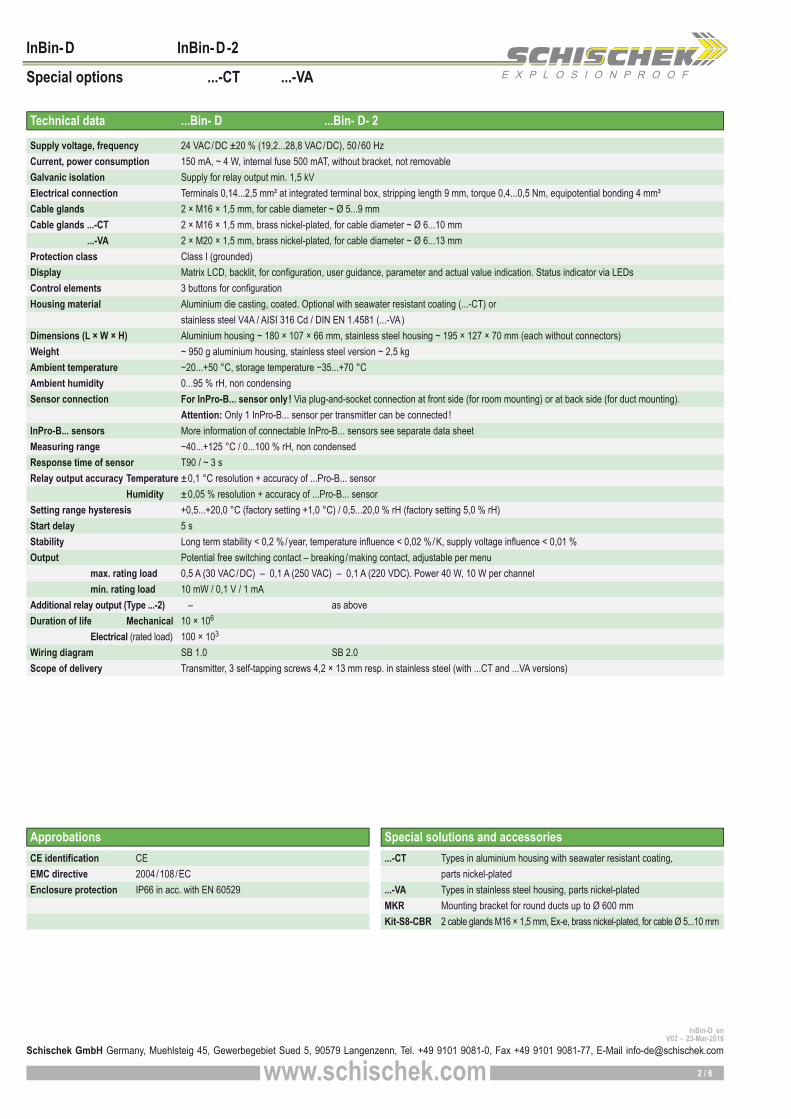
Technical data ...Bin- D ...Bin- D- 2
Approbations Special solutions and accessories...-CT Types in aluminium housing with seawater resistant coating, parts nickel-plated...-VA Types in stainless steel housing, parts nickel-platedMKR Mounting bracket for round ducts up to Ø 600 mmKit-S8-CBR 2 cable glands M16 × 1,5 mm, Ex-e, brass nickel-plated, for cable Ø 5...10 mm
Supply voltage, frequency 24 VAC/DC ±20 % (19,2...28,8 VAC/DC), 50 /60 Hz Current, power consumption 150 mA, ~ 4 W, internal fuse 500 mAT, without bracket, not removableGalvanic isolation Supply for relay output min. 1,5 kVElectrical connection Terminals 0,14...2,5 mm² at integrated terminal box, stripping length 9 mm, torque 0,4...0,5 Nm, equipotential bonding 4 mm²Cable glands 2 × M16 × 1,5 mm, for cable diameter ~ Ø 5...9 mm Cable glands ...-CT 2 × M16 × 1,5 mm, brass nickel-plated, for cable diameter ~ Ø 6...10 mm ...-VA 2 × M20 × 1,5 mm, brass nickel-plated, for cable diameter ~ Ø 6...13 mmProtection class Class I (grounded)Display Matrix LCD, backlit, for configuration, user guidance, parameter and actual value indication. Status indicator via LEDsControl elements 3 buttons for configurationHousing material Aluminium die casting, coated. Optional with seawater resistant coating (...-CT) or stainless steel V4A / AISI 316 Cd / DIN EN 1.4581 (...-VA) Dimensions (L × W × H) Aluminium housing ~ 180 × 107 × 66 mm, stainless steel housing ~ 195 × 127 × 70 mm (each without connectors)Weight ~ 950 g aluminium housing, stainless steel version ~ 2,5 kgAmbient temperature −20...+50 °C, storage temperature −35...+70 °CAmbient humidity 0...95 % rH, non condensingSensor connection For InPro-B... sensor only! Via plug-and-socket connection at front side (for room mounting) or at back side (for duct mounting). Attention: Only 1 InPro-B... sensor per transmitter can be connected !InPro-B... sensors More information of connectable InPro-B... sensors see separate data sheetMeasuring range −40...+125 °C / 0...100 % rH, non condensedResponse time of sensor T90 / ~ 3 sRelay output accuracy Temperature ±0,1 °C resolution + accuracy of ...Pro-B... sensor Humidity ±0,05 % resolution + accuracy of ...Pro-B... sensorSetting range hysteresis +0,5...+20,0 °C (factory setting +1,0 °C) / 0,5...20,0 % rH (factory setting 5,0 % rH)Start delay 5 sStability Long term stability < 0,2 %/year, temperature influence < 0,02 %/K, supply voltage influence < 0,01 %Output Potential free switching contact – breaking /making contact, adjustable per menu max. rating load 0,5 A (30 VAC/DC) – 0,1 A (250 VAC) – 0,1 A (220 VDC). Power 40 W, 10 W per channel min. rating load 10 mW / 0,1 V / 1 mAAdditional relay output (Type ...-2) – as aboveDuration of life Mechanical 10 × 106
Electrical (rated load) 100 × 103
Wiring diagram SB 1.0 SB 2.0Scope of delivery Transmitter, 3 self-tapping screws 4,2 × 13 mm resp. in stainless steel (with ...CT and ...VA versions)
CE identification CE EMC directive 2004/108/ECEnclosure protection IP66 in acc. with EN 60529
2 / 6

E X P L O S I O N P R O O F
! !
PA
PA
5
5
6
6
7
7
8
8
9
9
1
1
2
2
3
3
4
4
PE
PE
24 VAC/DC
24 VAC/DC
+
~
+
~
−~
−~
InBin-D SB 1.0
InBin-D-2 SB 2.0
SW-IN (G
ND)
SW-Ch1 (Sens
or 1)
SW-Ch2 (Sens
or 2)
SW-IN (G
ND)
SW-1 / S
ensor 1
SW-2 / S
ensor 1
SW-1 / S
ensor 2
SW-2 / S
ensor 2
U ≤ 10 V I ≤ 10 mAP ≤ 20 W
!
www.schischek.comSchischek GmbH Germany, Muehlsteig 45, Gewerbegebiet Sued 5, 90579 Langenzenn, Tel. +49 9101 9081-0, Fax +49 9101 9081-77, E-Mail [email protected]
InBin-D_enV02 – 23-Mar-2016
InBin-D InBin-D-2
Special options ...-CT ...-VA
Electrical connection Important information for installation and operationAll transmitters require a 24 VAC/DC power supply. The electrical wiring must be realized via the integrated terminal box. Attention: Before opening the terminal box cover, the supply voltage must be shut off !The supply has to be connected at terminals 1 (− /~) and 2 (+ /~).
Electric characteristics – For external InPro-B... sensor
Switching function normally open or closed can be selected via menu only.
Switching function normally open or closed can be selected via menu only.
Sensor 1: Temperature outputSensor 2: Humidity output
Sensor 1: Temperature outputSensor 2: Humidity output
Relay output 250 VAC / 0.1 A – 220 VDC / 0.1 A 30 VAC/DC / 0.5 A
Relay output 250 VAC / 0.1 A – 220 VDC / 0.1 A 30 VAC/DC / 0.5 A
At different relay and supply voltages (24 VAC/DC) the cable installation must be considered
(see “Information for Installation”) !
A. Installation, commissioning, maintenanceAll national and international standards, rules and regulations must be complied with. Apparatus must be installed in accordance with manufacturer instructions. If the equipment is used in a manner not specified by the manufacturer, the safety protec-tion provided by the equipment may be impaired.
Attention: Apply all rules and regulation before opening the internal terminal box. Do not open cover when circuits are live !
Draw the wiring cables through the cable glands. For connection use the internal terminal box and connect equipotential bonding. After connection install the cables in a fixed position and protect them against mechanical and thermical damage. Close all openings and ensure IP protection (min. IP66). Avoid temperature transfer and ensure not to exceed max. ambient temperature ! For outdoor installation a protective shield against sun, rain and snow should be applied.Sensors are maintenance free. An annual inspection is recommended. Clean with damp cloth only.Sensors must not be opened and repaired by the end user.B. Long cablingWe recommend using shielded signal wires and to connect one end of the shield to the ...Bin-... terminal box.C. Separate ground wiresFor supply and signal wires use separate grounds. D. Relay outputWires for safety extra-low voltage must be installed separately from other circuits. At 24 VAC/DC only supply and signal wires are permitted in one cable, in all other cases use separate or double isolated cables. An over-current protection fuse < 10 A has to be provided by the installer.E. InPro-B... sensorsThe InPro-B... sensor is supplied by the transmitter’s circuit. Unused connectors must be covered with a protective cap.
Depending on the ...Pro-B-... sensor’s type you can measure either temperature (...Pro-BT...) or humidity (...Pro-BF...) at the time or combined with a ...Pro-BTF... Simultane-ous measurings are not possible, use only one transmitter at the time.Before starting parametrisation of ...Bin-D... transmitter a ...Pro-B... sensor must be con-nected, which can be mounted either to the front or the back side of the transmitter. The protective cap must be removed. Unused connectors must be covered with the original protective cap to avoid mechanical damage and dirt !Depending on the sensor’s type you need to set parameters for one or two measuring ranges and their related data.
3 / 6

E X P L O S I O N P R O O F
°C, °F
Up, Down, Mid * nc, no
nc, no
% rF, % rH
Up, Down, Mid *
on, off
Yes, no, menu, dset (default setting)
www.schischek.comSchischek GmbH Germany, Muehlsteig 45, Gewerbegebiet Sued 5, 90579 Langenzenn, Tel. +49 9101 9081-0, Fax +49 9101 9081-77, E-Mail [email protected]
InBin-D_enV02 – 23-Mar-2016
InBin-D InBin-D-2
Special options ...-CT ...-VA
Operation → Parametrisationpush for min. 3 s
Parametrisation and commissioning
Menu Function ENTER Indication Select ENTER Next indication Select ENTER Next menuMenu 1 no function – menu skip
Menu 12 no function – menu skip
Menu 2 Unit sensor Select physical unit
Menu 7 Unit sensor Select physical unit
Menu 3 set 1, sensor 1 Select switching point 1 (temperature)
Menu 8 set 1, sensor 2 Select switching point 1 (humidity)Menu 9 set 2, sensor 2 (optional) * Select switching point 2 (humidity)
Menu 4 set 2, sensor 1 (optional) * Select switching point 2 (temperature)Menu 5 hysteresis, sensor 1 Select hysteresis
Menu 10 hysteresis, sensor 2 Select hysteresis
Menu 6 mode, sensor 1 Select switching properties (break contact, make contact)
Menu 11 mode, sensor 2 Select switching properties (break contact, make contact)
Menu 13 display setting Select display
enter temperature
enter temperature
enter degrees
enter humidity %
enter humidity %
enter humidity %
on, off
enter password
* for ...Bin-D-2 only (2-stage)
Menu 14 no function – menu skip
Menu 15 security Select password protection
Menu 16 save Select: save data, discard, back to menu, factory setting
(operation mode after “save”)
To change from operation to parametrisation mode push the “ENTER” button for minimum 3 seconds. If password protected: type password and push . Skip menu with , back to operation mode with menu “save”.
Display, buttons and parameters
Display for programming
and indication
Push button ENTER
Push button for level selection
Indication of data loggingThe flashing unit symbol (°C) shows that data is received and the device is working.
Sensor malfunctionA sensor malfunction is indicated by a red flashing LED and the text “SENS” in the display. The switching outputs will indicate that, too. In this case the connection between the tranducer and the sensor should be checked first.
Password inputThe default /delivery setup is 0000. In this configuration the password input is not activated. To activate the password protection (menu 15) change the 4 digits into your choosen numbers (e.g. 1234) and press ENTER. Please keep your password in mind for next parameter change ! Due to a new parameter setup the password is requested.
Change operation – parametrisation modeTo change from operation to parametrisation mode and vice versa, push ENTER button for minimum of 3 seconds. Back to operation mode with menu “save”.
Fig. ...Bin-D-2
4 / 6

E X P L O S I O N P R O O F
normal
normal normal
normal
normal
normal normal
normal normal
normal
normal
normal
www.schischek.comSchischek GmbH Germany, Muehlsteig 45, Gewerbegebiet Sued 5, 90579 Langenzenn, Tel. +49 9101 9081-0, Fax +49 9101 9081-77, E-Mail [email protected]
InBin-D_enV02 – 23-Mar-2016
InBin-D InBin-D-2
Special options ...-CT ...-VA
Menu 6 “mode” – Switching properties1. Define the device’s normal range first:
The device should indicate (green LED) when the temperature /humidity is▪ above the setpoints – mode „up-range“ has to be selected. ▪ below the setpoints – mode „down-range“ has to be selected.▪ between the setpoints – mode „mid-range“ has to be selected.
This mode is available for 2-stage devices only (...Bin-D-2).
2. Select the switching charateristic of the output relay:When the measured value is in normal range, the corresponding relays shall▪ close – select “normally closed” (nc) ▪ open – select “normally open” (no)
state
state
state state
state
state
state
state
state state
state
state
output switch 2 (optional)
output switch 2
output switch 2 (optional)
output switch 2 (optional)
output switch 2 (optional)
output switch 2
output switch 1
output switch 1
output switch 1
output switch 1
output switch 1
output switch 1
green
green
green green
green
green
green green
green
green
green
green
red
red
red red
red
red
red red
red
red
red
red
Hysteresis
Hysteresis
Hysteresis Hysteresis
Hysteresis
Hysteresis
Hysteresis
Hysteresis
Hysteresis Hysteresis
Hysteresis
Hysteresis
„UP range“ – „Normally Closed“ (nc)Normal range above setpoint – switch is closed
„Mid range“ – „Normally Closed“ (nc)Normal range between setpoints – switch is closed
„Down range“ – „Normally Closed“ (nc)Normal range below setpoint – switch is closed
„UP range“ – „Normally Open“ (no)Normal range above setpoint – switch is open
„Mid range“ – „Normally Open“ (no)Normal range between setpoints – switch is open
„Down range“ – „Normally Open“ (no)Normal range below setpoint – switch is open
If actual value is below the set value the switch contact opens.
If actual value is above the set value the switch contact opens.
If actual value is below the set value the switch contact closes.
If actual value is above the set value the switch contact closes.
2-stage devices
only
2-stage devices
only
2-stage: 2-stage:
setpoint 1
setpoint 1
setpoint 1
setpoint 1
setpoint 1
setpoint 1
setpoint 2
setpoint 2
setpoint 2
setpoint 2
setpoint 2
setpoint 2
5 / 6
E X P L O S I O N P R O O F
69
81.3
126.3
Ø 4.5
182.7
181.7
2
4.5
~ 61
70
26.7
~ 19
412
3.3
68
157,5
117
129
166
80107
55
6620
~ 18
0
Ø 4,5
Ø 4,5
Ø 4,5
...Pro-B...
www.schischek.comSchischek GmbH Germany, Muehlsteig 45, Gewerbegebiet Sued 5, 90579 Langenzenn, Tel. +49 9101 9081-0, Fax +49 9101 9081-77, E-Mail [email protected]
InBin-D_enV02 – 23-Mar-2016
InBin-D InBin-D-2
Special options ...-CT ...-VA
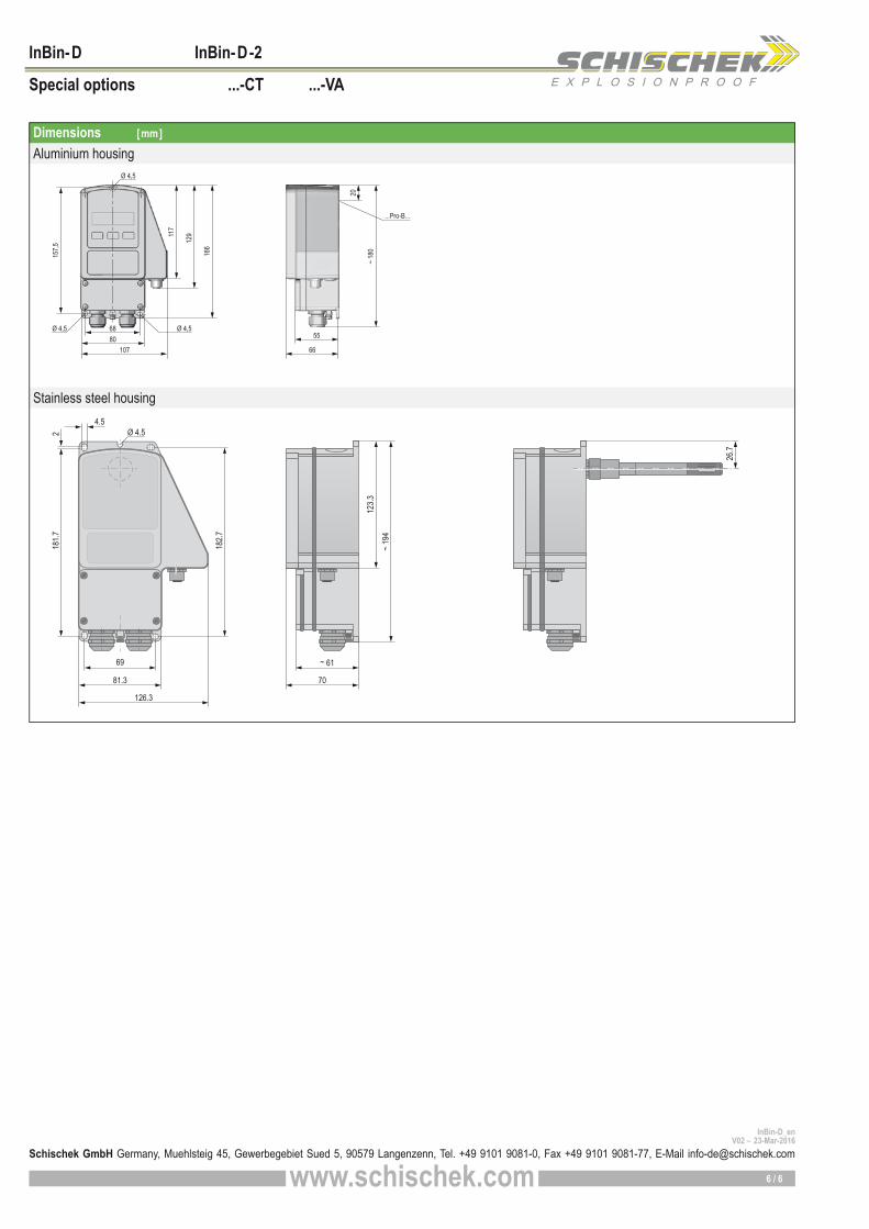
Aluminium housing
Stainless steel housing
Dimensions [mm]
6 / 6

E X P L O S I O N P R O O F
InPro-B...
Type Function Range Sensor length Connectable to Connection Installation area sensor
InPro-BT-... Temperature sensor −40...+125 °C* 50 / 100 / 150 / 200 mm InBin-D Plug and socket Safe areaInPro-BF-... Humidity sensor 0...100 % rH 50 / 100 / 150 / 200 mm InBin-D Plug and socket Safe areaInPro-BTF-... Combination sensor −40...+125 °C* / 0...100 % rH 50 / 100 / 150 / 200 mm InBin-D Plug and socket Safe area
Sensor length * at 50 mm length −40...+80 °C
www.schischek.com
Schischek GmbH Germany, Muehlsteig 45, Gewerbegebiet Sued 5, 90579 Langenzenn, Tel. +49 9101 9081-0, Fax +49 9101 9081-77, E-Mail [email protected]
InPro-B_en
V02 – 16-Aug-2016
Subject to change!
InPro-B Temperature /humidity sensor connectable exclusively to transmitters InBin-D for measuring of temperature and /or humidity
Description
InPro-B... sensor is a measuring element which is in combination with an ...Bin-D... transmitter for temperature, humidity or combination of temperature and humidity measuring. InPro-B... sensors are only for use with InBin-D... transmitters. The electromechanical connection is done with a socket on the front resp. on the back side of the transmitter, but only 1 InPro-B... per module is allowed and can be used. Warning: Aggressive gases can destroy the sensor element.
Accessories
Product views and applications
Temperature sensor Humidity sensor Temperature / humidity sensor
Measuring range −40...+125 °C * 0...100 % rH −40...+125 °C * / 0...100 % rH * −40...+80 °C at 50 mm length * −40...+80 °C at 50 mm lengthSensort types and length InPro-BT- 50 = 50 mm InPro-BF- 50 = 50 mm InPro-BTF- 50 = 50 mm InPro-BT-100 = 100 mm InPro-BF-100 = 100 mm InPro-BTF-100 = 100 mm InPro-BT-150 = 150 mm InPro-BF-150 = 150 mm InPro-BTF-150 = 150 mm InPro-BT-200 = 200 mm InPro-BF-200 = 200 mm InPro-BTF-200 = 200 mmResponse time sensor T90 / 20 s T90 / 4 s T90 / 20 s, T90 / 4 sAccuarcy temperature (max.) ±1,5 °C at −25...+85 °C (−25...+80 °C at 50 mm length), ±2,0 °C at −40...−25 °C and +85...+125 °C Accuarcy humidity ±3 % at 10...90 % rH, ±5 % at < 10 % rH and > 90 % rHAccuarcy ...Pro-BTF... Temperature: ±0,4 °C at 25 °C ±0,02 °C/°C Humidity: ±3 % at 10...90 % rH, ±5 % at < 10 % rH and > 90 % rHHousing protection IP66 acc. to EN 60529Material Adapter Stainless steel № 1.4305, length 50 mm in plastic PEEK-GF30 (max. room temperature +80 °C) Protection sleeve Stainless steel № 1.4301 / AISI 304 End cap AISI 316 Plug-in connector Zinc die-cast nickel-plated, screw sleeve brass nickel-platedFilter element humidity sensor Mesh size 100 μmAmbient temperature / humidity −40...+125 °C (−40...+80 °C at 50 mm length) / 0...100 % rHStorage temperature −40...+125 °C (−40...+80 °C at 50 mm length)Installation area sensor Safe areasScope of delivery InPro-B... sensor with plug connector and gasket (EPDM) for duct installation
Technical data InPro- BT -... InPro- BF -... InPro- BTF -...
Sensor for room application Sensor for duct application
MFK Mounting flange for duct mounting for variable immersion depth in ductsMKR Mounting bracket for round ducts up to Ø 600 mmTH-VA Immersion sleeve in stainless steel V4A / DIN EN 1.4571, length 120 mm.
Other length on request.Kit-FA-VA Stainless steel sinter filter cap for humidity sensors, pore size 10 μm.
Not for high humidity measurements!
Fig.: Humidity sensors
1 / 2

E X P L O S I O N P R O O F
InPro-B...
% rF°C
20 40 60 80 100 0 40 80 120 0−40
±5,0
±3,0
±2,0
±1,5
±1,0
±0,5
U ≤ 10 V I ≤ 10 mA P ≤ 20 W
InPro-B... -50 ...-100 ...-150 ...-200
...Pro-BT...
...Pro-BF...
...Pro-BTF...
200
3115
0
5010
0
Ø 12
Ø 23
15
www.schischek.com
Schischek GmbH Germany, Muehlsteig 45, Gewerbegebiet Sued 5, 90579 Langenzenn, Tel. +49 9101 9081-0, Fax +49 9101 9081-77, E-Mail [email protected]
InPro-B_en
V02 – 16-Aug-2016
Electric characteristics (max.)
Important information for installation and operation
Mounting room sensor (at terminal box side) Mounting duct sensor (back side)
Dimensions [mm]
For mounting the sensor must be plugged into the socket and screwed on the sensor by turning the lower knurled screw clock-wise. Tighten hand-screwed only. A small clearance between transmitter and sensor has to be accepted due to produc-tion conditions. MFK mounting flange for duct installation
For mounting the sensor must be plugged into the socket and screwed on the sensor by turning the lower knurled screw clockwise. Tighten hand-screwed only. A small clearance between transmitter and sensor has to be accepted due to production conditions.
The flange is to be moved over the sensor and fixed with the adjusting screw on the side. The flange can be mounted with 4 screws directly to the duct.
Height variably
adjustable
A. InPro-B... sensor
The power of InPro-B... sensor is supplied with the transmitter’s circuit. Unused sensor entries have to be closed with the black caps.B. Temperature flow
When measuring temperature over the max. allowed environmental temperature of the transmitter of +50 °C regard that no temperature flow over the sensor takes place.The mounting of the sensor has to ensure that errors due to heat dissipation are within the tolerance limits and the max. allowed environmental temperature is not exceeded. C. Mounting
Screw the sensor into the socket of the transmitter. The sensor cannot be opened as parts of the element are moulded. A small distance tolerance between transmitter and sensor has to be accepted due to production conditions.
Max. Medium temperature (surface temperature)
Max. medium temperature 125 °C (for sensor length 100–200 mm) 80 °C (for sensor length 50 mm)
Accuracy temperature Accuracy humidity + hysteresis
Accuracy temperature and humidity incl. hysteresis
Bottom side
Adapter
End cap
Protection
sleeve
Plug-in
connector with
screw sleeve
2 / 2