Embed Size (px)
Citation preview
1VD.C6.Q3.02 © Danfoss 02/2010DH-SMT/SI
Data sheet
Pressure independent balancing and control valve
AB-QM DN 10-250
Easy implementation:
Benefits: Description
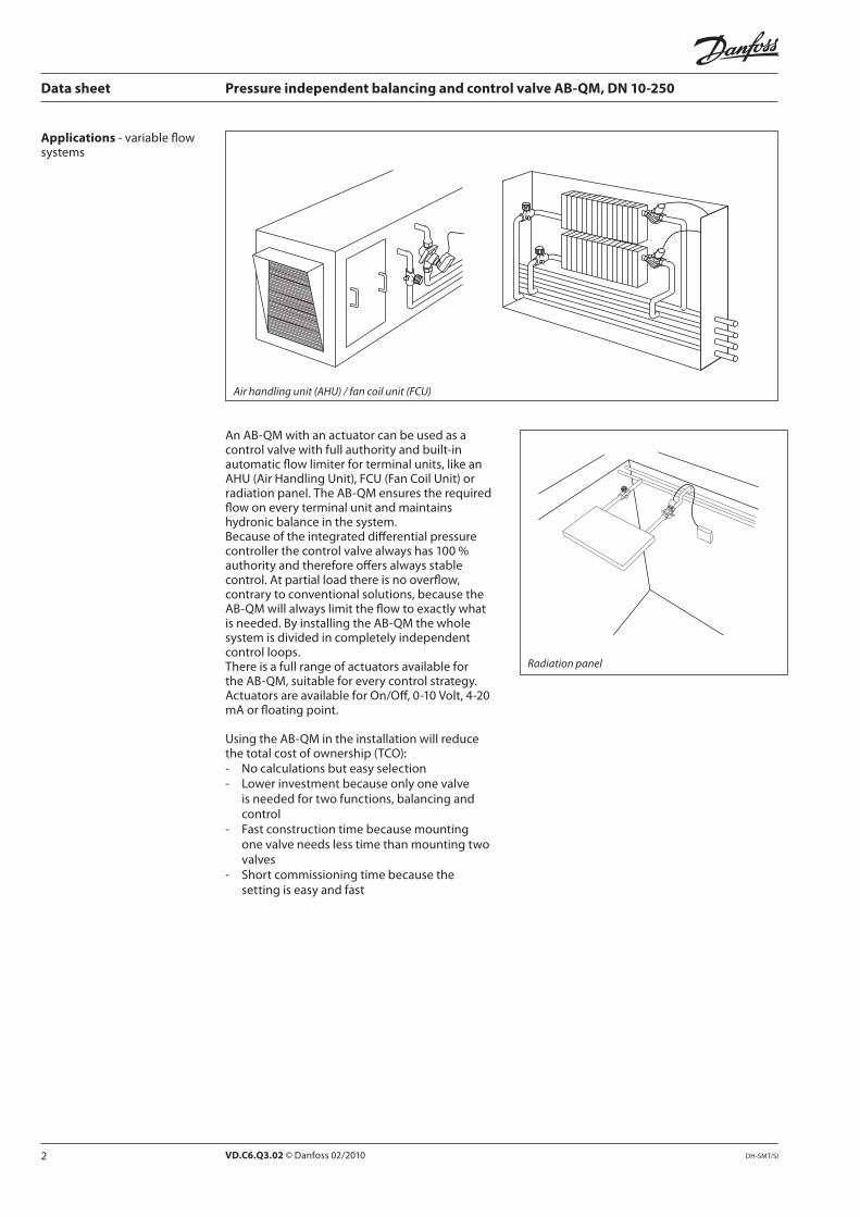
The AB-QM valve equipped with an actuator is a control valve with full authority and an automatic balancing function / flow limitation. Typical applications
are: Temperature control with permanent automatic balancing on terminal units (chillers, air-handling units, fan coils, induction units, radiation panels and
heat exchangers).
2 VD.C6.Q3.02 © Danfoss 02/2010 DH-SMT/SI
Data sheet Pressure independent balancing and control valve AB-QM, DN 10-250
Applications
Air handling unit (AHU) / fan coil unit (FCU)
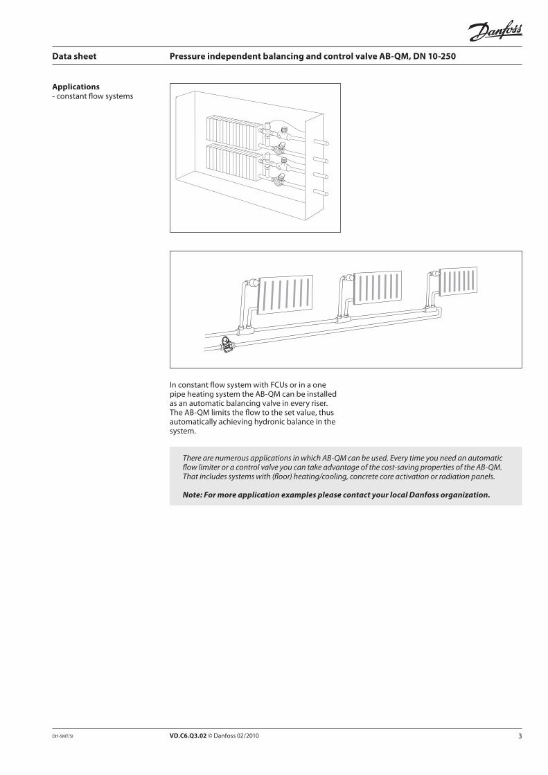
Radiation panel
3VD.C6.Q3.02 © Danfoss 02/2010DH-SMT/SI
Data sheet Pressure independent balancing and control valve AB-QM, DN 10-250
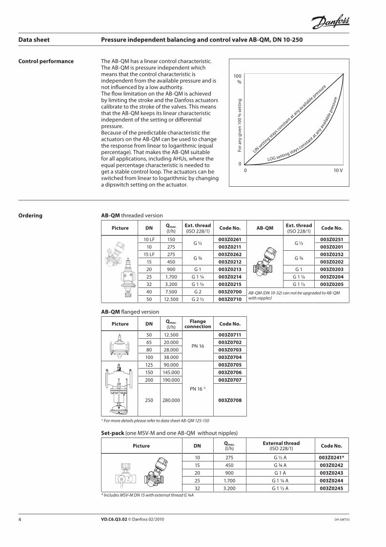
Applications
There are numerous applications in which AB-QM can be used. Every time you need an automatic flow limiter or a control valve you can take advantage of the cost-saving properties of the AB-QM. That includes systems with (floor) heating/cooling, concrete core activation or radiation panels.
Note: For more application examples please contact your local Danfoss organization.
VD.C6.Q3.02 © Danfoss 02/2010 DH-SMT/SI
LI s
n s
as
onsan
a a
n a
aab
ss
LOG sn
s as ons
an a
an
aa
ab
ss
0
100
Data sheet Pressure independent balancing and control valve AB-QM, DN 10-250
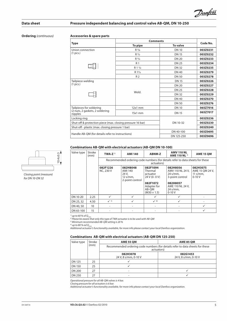
Ordering AB-QM
Picture DNQmax. Ext. thread
Code No. AB-QMExt. thread
Code No.
150G ½
003Z0261G ½
003Z0251
10 275 003Z0211 003Z0201
275G ¾
003Z0262G ¾
003Z0252
15 003Z0212 003Z0202
20 900 G 1 003Z0213 G 1 003Z0203
25 G 1 ¼ 003Z0214 G 1 ¼ 003Z0204
32 G 1 ½ 003Z0215 G 1 ½ 003Z0205
G 2 003Z0700 AB-QM (DN 10-32) can not be upgraded to AB-QM with nipples!50 G 2 ½ 003Z0710
AB-QM
Picture DNQmax. Flange
connectionCode No.
50 003Z0711
003Z0702
003Z0703
100 003Z0704
125 003Z0705
150 003Z0706
200 003Z0707
250 003Z0708
1) For more details please refer to data sheet AB-QM 125-150
Control performance
Set-pack
Picture DNQmax. External thread
Code No.
10 275 003Z0241*
15 003Z0242
20 900 003Z0243
25 003Z0244
32 003Z0245
* Includes MSV-M DN 15 with external thread G ¾A
5VD.C6.Q3.02 © Danfoss 02/2010DH-SMT/SI
Data sheet Pressure independent balancing and control valve AB-QM, DN 10-250
Accessories & spare parts
TypeComments
Code No.To pipe To valve
R / 003Z0231
R / 003Z0232
R / 003Z0233
R 1 003Z0234
R 1 / 003Z0235
R 1/ 003Z0279
R 2 003Z0278
003Z0226
003Z0227
003Z0228
003Z0229
003Z0270
003Z0276
065Z7016
065Z7017
003Z0236
003Z0230
003Z0240
003Z0695
003Z0696
Ordering (continuous)
Combinations AB-QM with electrical actuators (AB-QM DN 10-100)
TWA-Z AMI 140 ABNM-ZAMV 110 NL
AME 110 NL AME 15 QM
082F1226 082H8048
082F1094
082F1072
082H8056
082H8057
082H3075
ü ü ü ü -
ü ü ü ü -
10 - - - - ü
15 - - - - ü
1) up to 60 % of Qmax2) Please be aware that only this type of TWA actuator is to be used with AB-QM3) Minimum recommended AB-QM setting is 20 %4) up to 80 % od Qmax
Additional actuator’s functionality available, for more info please contact your local Danfoss organization.
Combinations AB-QM with electrical actuators (AB-QM DN 125-250)
AME 55 QM AME 85 QM
082H3078 082G1453
25 ü
25 ü
27 - ü
27 - ü
Operational pressure for all AB-QM valves is 4 bar. Closing pressure for all actuators is 6 bar.Additional actuator’s functionality available, for more info please contact your local Danfoss organization.
Closing point (measure)
for DN 10-DN 32
VD.C6.Q3.02 © Danfoss 02/2010 DH-SMT/SI
Data sheet Pressure independent balancing and control valve AB-QM, DN 10-250
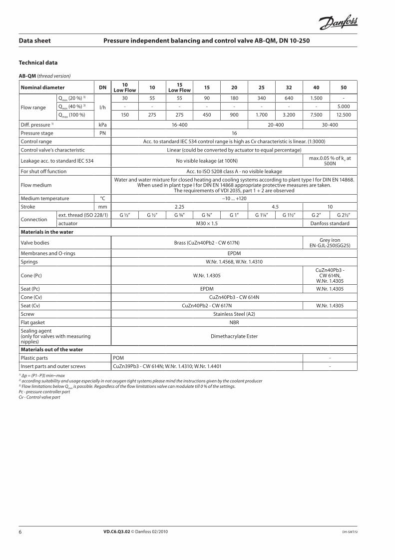
Technical data
AB-QM thread version)
Nominal diameter DN10
Low Flow10
15 Low Flow
15 20 25 32 40 50
30 55 55 90 -
- - - - - - - -
150 275 275 900
10
G ½” G ½” G ¾” G ¾” G 1” G 1¼” G 1½” G 2” G 2½”
Materials in the water
Materials out of the water
POM -
-
1) ∆p = (P1–P3) min~max 2) according suitability and usage especially in not oxygen tight systems please mind the instructions given by the coolant producer3) Flow limitations below Qmin is possible. Regardless of the flow limitations valve can modulate till 0 % of the settings.Pc - pressure controller partCv - Control valve part
7VD.C6.Q3.02 © Danfoss 02/2010DH-SMT/SI
Data sheet Pressure independent balancing and control valve AB-QM, DN 10-250
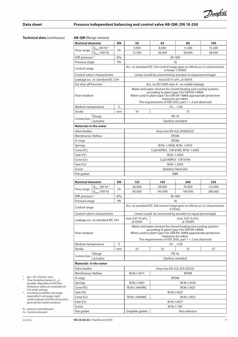
Technical data (continuous) AB-QM
Nominal diameter DN 50 65 80 100
10 15
Materials in the water
Nominal diameter DN 125 150 200 250
25 25 27 27
Materials in the water
1) ∆p = (P1–P3) min~max 2) Flow limitations below Qmin is
possible. Regardless of the flow limitations valve can modulate till 0 % of the settings.
3) according suitability and usage especially in not oxygen tight systems please mind the instructions given by the coolant producer
Pc - pressure controller partCv - Control valve part
VD.C6.Q3.02 © Danfoss 02/2010 DH-SMT/SI
1
5
6
7
8
2
3
4
P2-P3
P1-P3
P1 P2 P3
Data sheet Pressure independent balancing and control valve AB-QM, DN 10-250
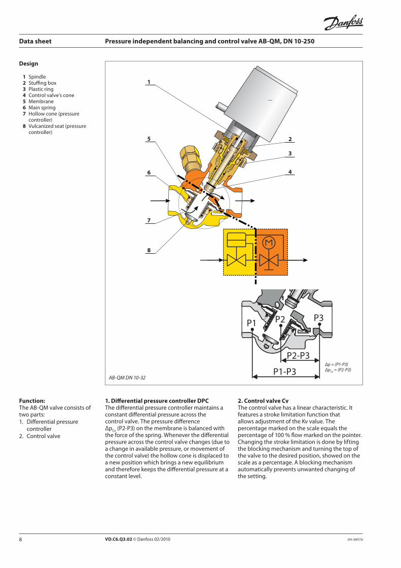
Design
1 2 3 4 5 6 7
8
1. Differential pressure controller DPC
2. Control valve Cv Function:
∆p = (P1-P3)∆pCv = (P2-P3)
AB-QM DN 10-32
9VD.C6.Q3.02 © Danfoss 02/2010DH-SMT/SI
P1 P3
Data sheet Pressure independent balancing and control valve AB-QM, DN 10-250
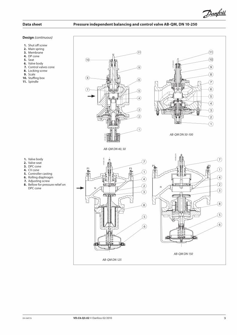
AB-QM DN 40, 50
AB-QM DN 50-100
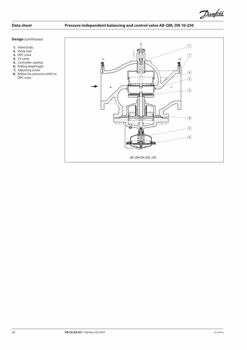
Design (continuous)
1. 2. 3. 4. 5. 6. 7. 8. 9. 10. 11.
AB-QM DN 150
P1 P3
1. 2. 3. 4. 5. 6. 7. 8.
AB-QM DN 125
10 VD.C6.Q3.02 © Danfoss 02/2010 DH-SMT/SI
Data sheet Pressure independent balancing and control valve AB-QM, DN 10-250
Design (continuous)
1. 2. 3. 4. 5. 6. 7. 8.
AB-QM DN 200, 250
P1 P3
11VD.C6.Q3.02 © Danfoss 02/2010DH-SMT/SI
Data sheet Pressure independent balancing and control valve AB-QM, DN 10-250
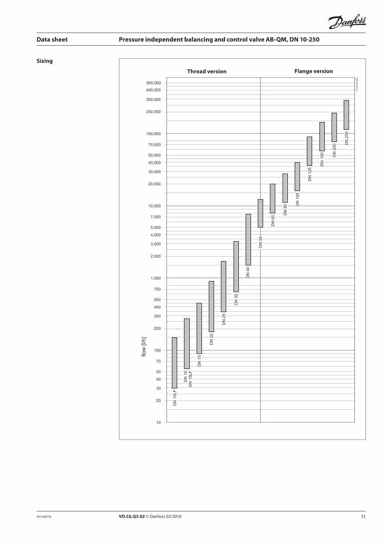
Thread version Flange version
Sizing
12 VD.C6.Q3.02 © Danfoss 02/2010 DH-SMT/SI
Data sheet Pressure independent balancing and control valve AB-QM, DN 10-250
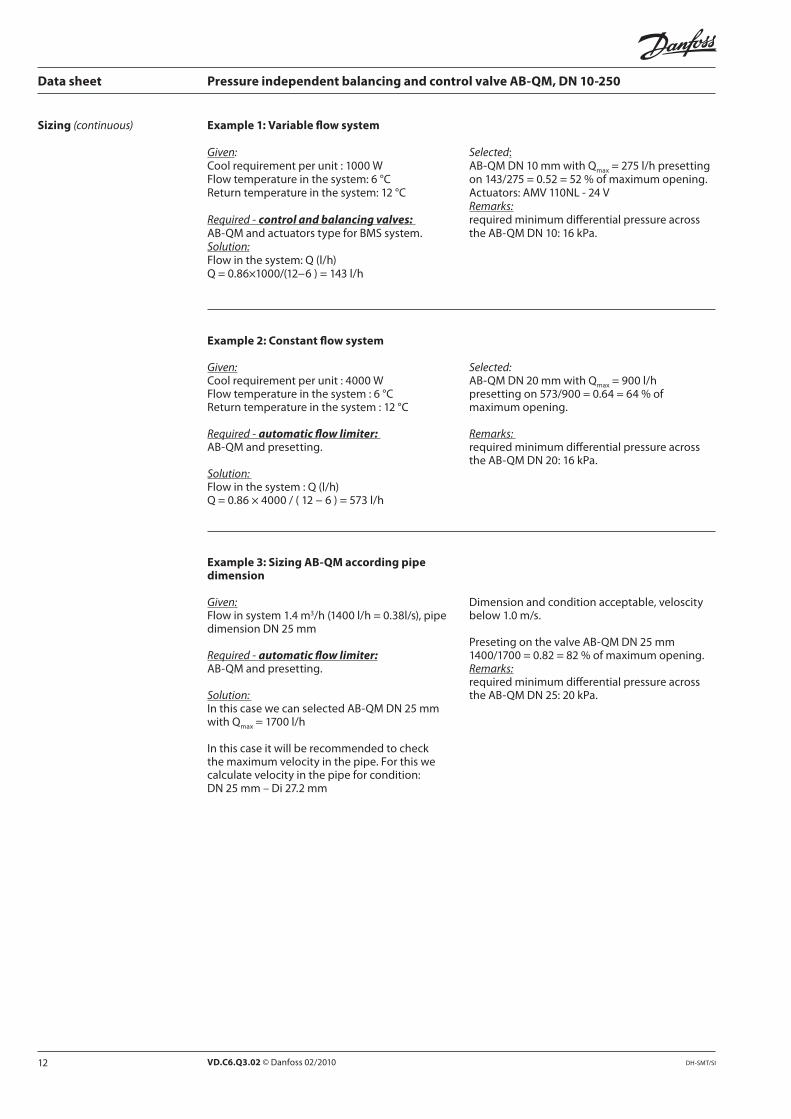
Sizing (continuous)
Example 1: Variable flow system
Given:
Required - control and balancing valves:
Solution:
Selected
Remarks:
Example 2: Constant flow system
Given:
Required - automatic flow limiter:
Solution:
Selected:
Remarks:
Example 3: Sizing AB-QM according pipe dimension
Given: 3
Required - automatic flow limiter:
Solution:
Remarks:
13VD.C6.Q3.02 © Danfoss 02/2010DH-SMT/SI
P2-P3
P2-P3
P2-P3
P
a a
P1-P3
P1-P3
P1 P2 P3
Data sheet Pressure independent balancing and control valve AB-QM, DN 10-250
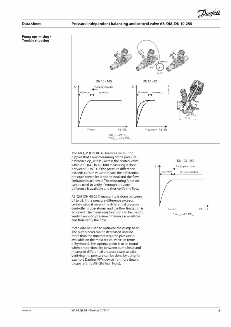
Pump optimising / Trouble shooting
* ∆pmin = (P1-P3)min
** ∆pcv.min = (P2-P3)min
* ∆pmin = (P1–P3)min
VD.C6.Q3.02 © Danfoss 02/2010 DH-SMT/SI
≠
–
Data sheet Pressure independent balancing and control valve AB-QM, DN 10-250
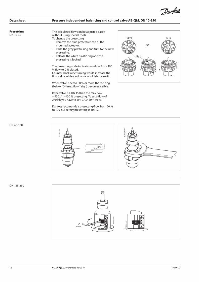
Presetting
15VD.C6.Q3.02 © Danfoss 02/2010DH-SMT/SI
Data sheet Pressure independent balancing and control valve AB-QM, DN 10-250
Service DN 10-32
code 065F0006
code 003Z0236
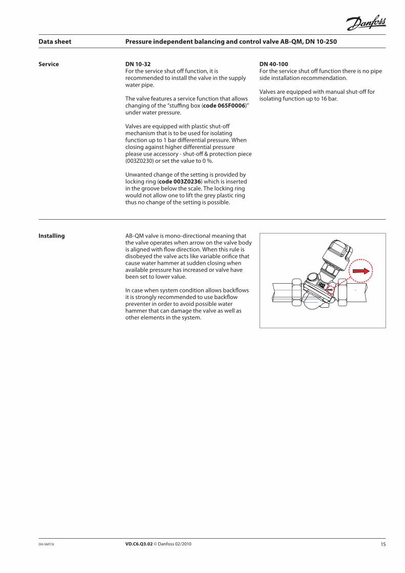
Installing
DN 40-100
VD.C6.Q3.02 © Danfoss 02/2010 DH-SMT/SI
Data sheet Pressure independent balancing and control valve AB-QM, DN 10-250
Supplier of the valve should provide lab test results
Supplier of the valve should provide lab test results
________
________
________
____
1) Since there is no standard for testing procedure, Danfoss recommends verification by independent
Tender text
17VD.C6.Q3.02 © Danfoss 02/2010DH-SMT/SI
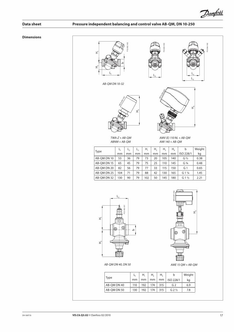
TWA-Z + AB-QM
ABNM + AB-QM
H3
AMV (E) 110 NL + AB-QM
AMI 140 + AB-QM
H
Data sheet Pressure independent balancing and control valve AB-QM, DN 10-250
L2
L3
L2
L1
H2
H1
b
AB-QM DN 10-32
Dimensions
L1
L2
L3
H1
H2
H3
H b
53 79 73 20 105 G ½
79 75 25 110 G ¾
79 77 33 115 150 G 1
71 79 130 G 1 ¼
130 90 79 102 50 G 1 ½
H1
L2
H2
b
AB-QM DN 40, DN 50
H3
AME 15 QM + AB-QM
L1
H1
H2
H3
b
110 192 315 G 2
130 192 315 G 2 ½
VD.C6.Q3.02 © Danfoss 02/2010 DH-SMT/SI
Data sheet Pressure independent balancing and control valve AB-QM, DN 10-250
a
H2
H1
L1
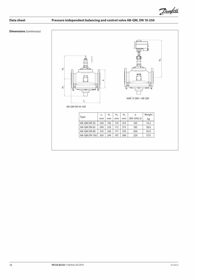
AB-QM DN 50-100
H3
AME 15 QM + AB-QM
Dimensions (continuous)
L1
H1
H2
H3
a
230 192 315
290 233 172 373
310 177 200
350 220
19VD.C6.Q3.02 © Danfoss 02/2010DH-SMT/SI
H2
H1
a
L1
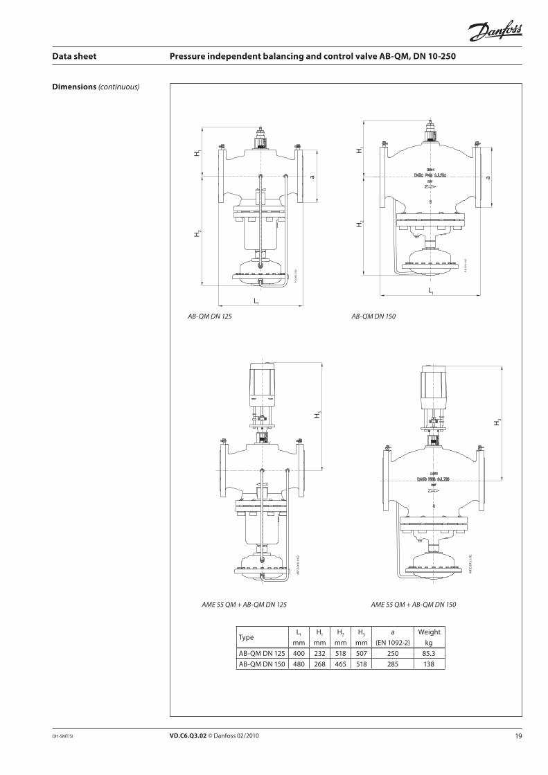
AB-QM DN 125
H2
H1
L1
a
H3
AME 55 QM + AB-QM DN 125
H3
AME 55 QM + AB-QM DN 150
Data sheet Pressure independent balancing and control valve AB-QM, DN 10-250
AB-QM DN 150
Dimensions (continuous)
L1
H1
H2
H3
a
232 507 250
20 VD.C6.Q3.02
H3
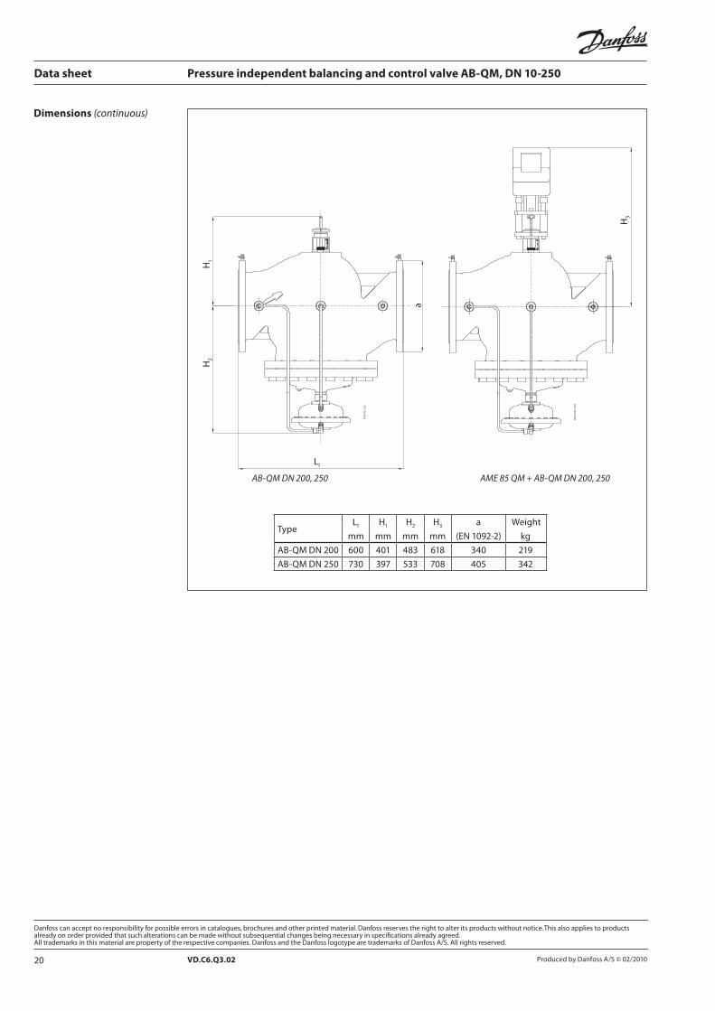
AME 85 QM + AB-QM DN 200, 250
a
L1
H2
H1
AB-QM DN 200, 250
Data sheet Pressure independent balancing and control valve AB-QM, DN 10-250
Dimensions (continuous)
L1
H1
H2
H3
a
219
730 397 533


![Honeywell Pressure Switches · 2016-04-30 · Honeywell Pressure Switches High Pressure: HP Series, HE Series Factory set 150 psi to 4500 psi [10,34 bar to 310,26 bar] Low Pressure:](https://img.pdfslide.us/doc/110x75/5f842218cd8bc44621178411/honeywell-pressure-2016-04-30-honeywell-pressure-switches-high-pressure-hp-series.jpg)