Embed Size (px)
Citation preview

PARA LIGHT ELECTRONICS CO., LTD. 11F., No. 8, Jiankang Rd., Zhonghe Dist., New Taipei City 235, Taiwan, Tel: 886-2-2225-3733 Fax: 886-2-2225-4800 E-mail: [email protected] www.paralighttaiwan.com
DATA SHEET
PART NO.: L-T650WDT
REV: C / 1
CUSTOMER’S APPROVAL : _______________ DCC : ____________ DRAWING NO. : DS-7B-06-0001 DATE : 2019-07-15 PAGE 1 of 17 PARA-FOR-065
Release by
PARALIGHTDCC

SURFACE MOUNT DEVICE LED
Part No. : L-T650WDT REV: C / 1
Features
Top view, Wide view angle, White color PLCC 2 package SMD LED .
EIA STD package, packing in 8mm tape on 7" diameter reels (ANSI/EIA-481-B-2001).
Compatible with automatic Pick & Place equipment.
Compatible with IR Reflow soldering and TTW soldering.
Pb free product and acceptable lead-free process! Meet RoHS Green Product.
Application
Backlighting (LCD, Switches, keys, displays, illuminated advertising)
Emergency lighting / Signal and symbol luminaries.
Package Outline Dimensions
3.00
C0.45
2.70
1.90
0.75
1.3
0
1.2
0
0.9
0
1.4
0
50
°
TOP VIEW
BACK VIEW
SIDE VIEW
FRONT VIEW
2.0
0
POLARITY + -
0.15±0.03
3°
50°
Notes:
1. All dimensions are in millimeters.
2. Tolerance is ± 0.10mm (.004") unless otherwise noted.
DRAWING NO. : DS-7B-06-0001 DATE : 2019-07-15 PAGE 2 of 17
PARA-FOR-068
Release by
PARALIGHTDCC

SURFACE MOUNT DEVICE LED
Part No. : L-T650WDT REV: C / 1
Chip Materials
Dice Material : InGaN
Light Color : White
Lens Color : Light Yellow Diffused.
Absolute Maximum Ratings(Ta=25℃)
Symbol Parameter Rating Unit
PD Power Dissipation 75 mW
IPF Peak Forward Current
(1/10 Duty Cycle, 0.1ms Pulse Width) 100 mA
IF Continuous Forward Current 20 mA
VR Reverse Voltage 5 V
ESD Electrostatic Discharge Threshold (HBM)Note A 1000 V
Topr Operating Temperature Range -40 ~ + 85 ℃
Tstg Storage Temperature Range -40 ~ + 85 ℃
Note A :
HBM : Human Body Model. Seller gives no other assurances regarding the ability of to
withstand ESD.
Electro-Optical Characteristics (Ta=25℃)
Parameter Symbol Min. Typ. Max. Unit Test Condition
Luminous Intensity IV 2200 2350 3050 mcd IF=20mA
Viewing Angle 2θ1/2 120 Deg Note 2
CIE Chromaticity x 0.31 IF=20mA
CIE Chromaticity y 0.32
Forward Voltage VF 3.20 3.50 V IF = 20mA
Reverse Current IR 10 μA VR = 5V
DRAWING NO. : DS-7B-06-0001 DATE : 2019-07-15 PAGE 3 of 17 PARA-FOR-068
Release by
PARALIGHTDCC

SURFACE MOUNT DEVICE LED
Part No. : L-T650WDT REV: C / 1
Notes: 1. Luminous intensity is measured with a light sensor and filter combination that
proximities the CIE eye-response curve.
2. θ1/2 is the off-axis angle at which the luminous intensity is half the axial luminous
intensity.
3. Caution in ESD :
Static Electricity and surge damages the LED. It is recommended use a wrist band or
anti-electrostatic glove when handling the LED. All devices, equipment and machinery
must be properly grounded.
4. Major standard testing equipment by “Instrument System” Model : CAS140B Compact
Array Spectrometer and “KEITHLEY” Source Meter Model : 2400.
Typical Electro-Optical Characteristics Curves
Fig.1 Relative Intensity vs. Wavelength
DRAWING NO. : DS-7B-06-0001 DATE : 2019-07-15 PAGE 4 of 17
PARA-FOR-068
Release by
PARALIGHTDCC

SURFACE MOUNT DEVICE LED
Part No. : L-T650WDT REV: C / 1
Typical Electro-Optical Characteristics Curves
(25℃ Ambient Temperature Unless Otherwise Noted)
Ta=25 C IFP=20mAIFP=60mAIFP=20mAIFP=5mA
Ta=25 C IFP=20mA
Ta=25 C Ta=25 C
x
Fig.9 Forward Current vs.Chromaticity Coordinate
100mA
50mA
1mA
20mA
5mA
-30 C
0 C
25 C 50°C85 C
Fig.8 Ambient Temperature vs.Chromaticity Coordinate
x Ambient Temperature Ta( C )
Fig.7 Ambient Temperature vs.Forward Voltage
Fig.6 Forward Current Derating Curve
Ambient Temperature Ta( C )
110
5 10 5020 100All
owab
le F
orw
ard
Cur
rent
IF
P(m
A)
20
30
50
100
200
0.5
Fig.5 Spatial Distribution
20 10 0
30
40
50
60
70
0.9
0.8
1.0
80 90
0.60.2 0.40.30.5 0.1
0.7
Rel
ativ
e L
umin
ous
lnte
nsity
Nor
mal
ized
of
20m
A
Fig.3 Relative Luminous Intensity vs.Forward Current
50
40
30
20
10For
war
d C
urre
nt I
F(m
A)
2
1
0.2
Fig.1 Forward Current vs.Forward Voltage
10060 8040200
0
Ambient Temperature Ta( C )
Fig.2 Forward Current Derating Curve
1008060200
0.1
-40 -20 40
Ambient Temperature Ta( C )Fig.4 Luminous Intensity vs.Ambient Temperature
Rel
ativ
e lu
min
ous
inte
nsity
DRAWING NO. : DS-7B-06-0001 DATE : 2019-07-15 PAGE 5 of 17 PARA-FOR-068
Release by
PARALIGHTDCC

SURFACE MOUNT DEVICE LED
Part No. : L-T650WDT REV: C / 1
Bin Code List
Luminous
Intensity(IV),Unit:mcd@20mA
Forward Voltage(VF),
Iv bin code(sub code-2) Unit:V@20mA
Bin Code MIN Max Bin Code MIN Max
H163 2200 2250 13 2.80 2.90
H164 2250 2300 14 2.90 3.00
H165 2300 2400 15 3.00 3.10
H171 2400 2500 16 3.10 3.20
H172 2500 2600 17 3.20 3.30
H173 2600 2750 18 3.30 3.40
H174 2750 2900 19 3.40 3.50
H175 2900 3050
Tolerance of each bin are±10% Tolerance of each bin are±0.1V.
DRAWING NO. : DS-7B-06-0001 DATE : 2019-07-15 PAGE 6 of 17 PARA-FOR-068
Release by
PARALIGHTDCC
SURFACE MOUNT DEVICE LED
Part No. : L-T650WDT REV: C / 1
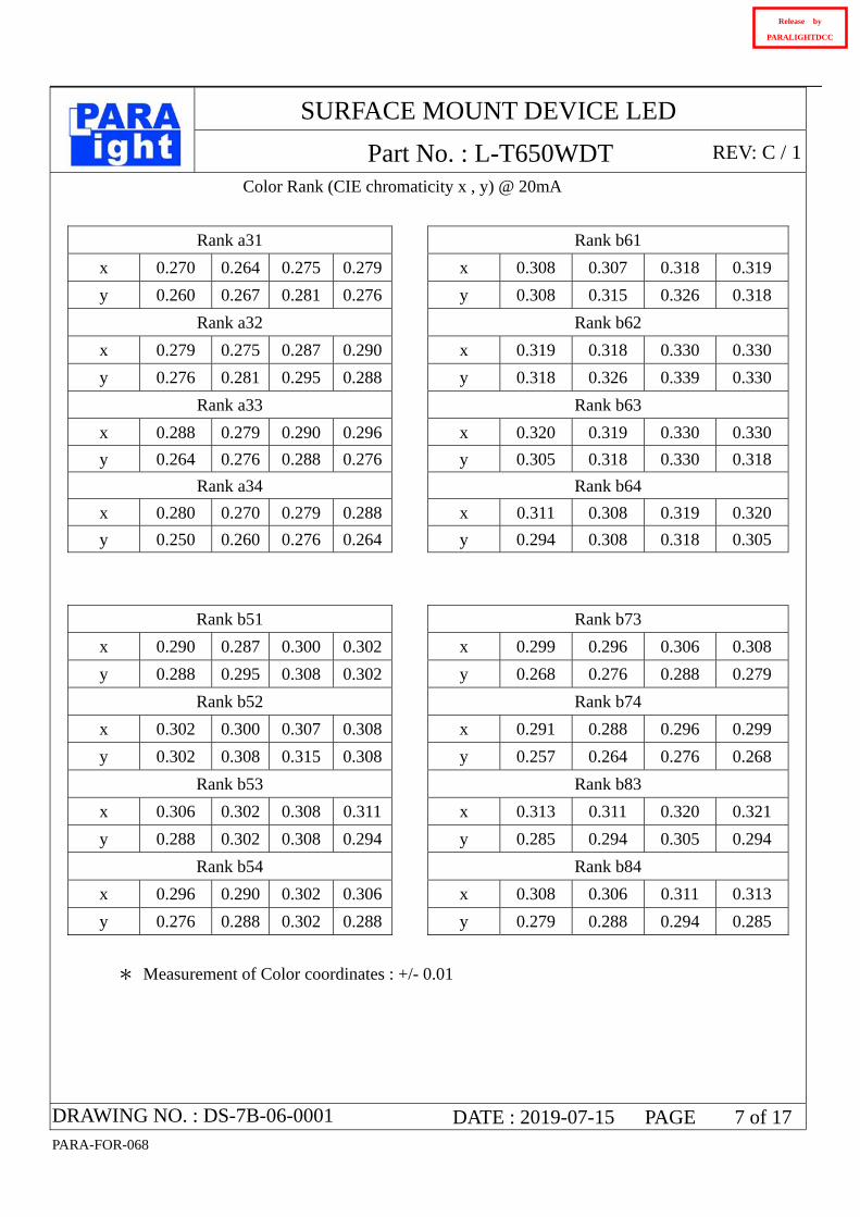
Color Rank (CIE chromaticity x , y) @ 20mA
Rank a31 Rank b61
x 0.270 0.264 0.275 0.279 x 0.308 0.307 0.318 0.319
y 0.260 0.267 0.281 0.276 y 0.308 0.315 0.326 0.318
Rank a32 Rank b62
x 0.279 0.275 0.287 0.290 x 0.319 0.318 0.330 0.330
y 0.276 0.281 0.295 0.288 y 0.318 0.326 0.339 0.330
Rank a33 Rank b63
x 0.288 0.279 0.290 0.296 x 0.320 0.319 0.330 0.330
y 0.264 0.276 0.288 0.276 y 0.305 0.318 0.330 0.318
Rank a34 Rank b64
x 0.280 0.270 0.279 0.288 x 0.311 0.308 0.319 0.320
y 0.250 0.260 0.276 0.264 y 0.294 0.308 0.318 0.305
Rank b51 Rank b73
x 0.290 0.287 0.300 0.302 x 0.299 0.296 0.306 0.308
y 0.288 0.295 0.308 0.302 y 0.268 0.276 0.288 0.279
Rank b52 Rank b74
x 0.302 0.300 0.307 0.308 x 0.291 0.288 0.296 0.299
y 0.302 0.308 0.315 0.308 y 0.257 0.264 0.276 0.268
Rank b53 Rank b83
x 0.306 0.302 0.308 0.311 x 0.313 0.311 0.320 0.321
y 0.288 0.302 0.308 0.294 y 0.285 0.294 0.305 0.294
Rank b54 Rank b84
x 0.296 0.290 0.302 0.306 x 0.308 0.306 0.311 0.313
y 0.276 0.288 0.302 0.288 y 0.279 0.288 0.294 0.285
* Measurement of Color coordinates : +/- 0.01
DRAWING NO. : DS-7B-06-0001 DATE : 2019-07-15 PAGE 7 of 17 PARA-FOR-068
Release by
PARALIGHTDCC

SURFACE MOUNT DEVICE LED
Part No. : L-T650WDT REV: C / 1
C.I.E Chromaticity Diagram
C.I.E. 1931 Chromaticity Diagram
-0.1
0
0.1
0.2
0.3
0.4
0.5
0.6
0.7
0.8
0.9
-0.1 0 0.1 0.2 0.3 0.4 0.5 0.6 0.7 0.8 0.9
x
y
DRAWING NO. : DS-7B-06-0001 DATE : 2019-07-15 PAGE 8 of 17 PARA-FOR-068
Release by
PARALIGHTDCC

SURFACE MOUNT DEVICE LED
Part No. : L-T650WDT REV: C / 1
Label Explanation
CUS. PART NO: To be denominated.
CUSTOMER: To be denominated.
PART NO: Refer to P17
IV--- Luminous Intensity Code
VF--- Forward Voltage Code
CIE--- Color Rank Code
LOT NO: E L P 9 4 0001
A---E: For series number
B---L: Local F: Foreign
C---P: PLCC SMD
D---Year
E---Month
F---SPEC.
PACKING QUANTITY OF BAG :
3000pcs for T670 series
3000pcs for T650 series
3000pcs for S020 series
DATE CODE:2009 04 01
G H I
G--- Year
H--- Month
I --- Day
DRAWING NO. : DS-7B-06-0001 DATE : 2019-07-15 PAGE 9 of 17 PARA-FOR-068
A B C D E F
Release by
PARALIGHTDCC

SURFACE MOUNT DEVICE LED
Part No. : L-T650WDT REV: C / 1
Reel Dimensions
Notes:
1. Taping Quantity : 3000pcs max
2. The tolerances unless noted is±0.1mm, Angle±0.5°, Unit: mm.
Suggest Soldering Pad Dimensions
1.121.34
1.80
DRAWING NO. : DS-7B-06-0001 DATE : 2019-07-15 PAGE 10 of 17PARA-FOR-068
Release by
PARALIGHTDCC

SURFACE MOUNT DEVICE LED
Part No. : L-T650WDT REV: C / 1
Package Dimensions Of Tape And Reel
7
*3.2
3∮0.
10(.
127∮
.004
)
*0.254∮0.020(.0100∮.0008)
*1.73∮0.10(.068∮.004)
-0.1
0*8
.00+
0.30
( )
-.004
0.315+.01
2
3.50
∮.05
(.13
8∮.0
02)
1.75
∮0.1
0(.
069∮
.004
)
2.00∮0.05(.079∮.002)
4.00∮0.10(.157∮.004)
4.00∮0.10(.157∮.004)
User Feed Direction
Notes: All dimensions are in millimeters.
Packaging Of Electronic Components On Continuous Tapes
DRAWING NO. : DS-7B-06-0001 DATE : 2019-07-15 PAGE 11 of 17PARA-FOR-068
Release by
PARALIGHTDCC

SURFACE MOUNT DEVICE LED
Part No. : L-T650WDT REV: C / 1
Moisture Resistant Packaging
Label
Aluminum moistue-proof bag Desiccant
Label
H:\S
MD
\SM
D\S
MD
°ü
×°
\±ê
??
.jpg
H:\S
MD
\SM
D\S
MD
°ü
×°
\±ê
??
.jpg
H:\S
MD
\SM
D\S
MD
°ü
×°
\±ê
??
.jpg
H:\SM
D\SM
D\SM
D°
ü×
°\±
ê?
?.jpg
255
435
145
240
210
Label Box
Carton
Reel
Notes : One reel in a bag, one bag in a inner box, ten inner boxes in a carton. Unit : mm.
Cleaning
If cleaning is required , use the following solutions for less than 1 minute and less than 40℃.
Appropriate chemicals: isopropyl alcohol. (When using other solvents, it should be confirmed
beforehand whether the solvents will dissolve the package and the resin or not.)
Effect of ultrasonic cleaning on the LED resin body differs depending on such factors as
ultrasonic power and the assembled condition. Before cleaning, a pre-test should be
confirm whether any damage to the LEDS will occur.
DRAWING NO. : DS-7B-06-0001 DATE : 2019-07-15 PAGE 12of 17PARA-FOR-068
Release by
PARALIGHTDCC

SURFACE MOUNT DEVICE LED
Part No. : L-T650WDT REV: C / 1
● Suggest Sn/Pb IR Reflow Soldering Profile Condition:
-
Profile Feature Sn99Ag0.3Cu0.7 Sn64Bi35Ag1
Preheat ram p-up ra te 1 3 °C/second 1 3 °C/second
T 120°C 110 °C
0 °C 160 °C
9 3
(Tsm in to Tsm ax) econd 2 econd
°C 178 °C
second 60 90 second
Tp (tp)
4
- -
-
em perature m in (Tsm in)
Tem perature m ax (Tsm ax)
Tim e (Tsm in to Tsm ax) (t ) 0-120 seconds 60-1 0 seconds
Average ram p-up ra te 2 °C/s m ax. °C/s m ax.
L iquidous tem pera ture (T )
Tim e a t l iquidous (t )
Peak tem perature (Tp) °C 210°C
Tim e within 5 °C of the 20s 20s
Average ram p-down rate (Tp to Tsm ax) 4 °C/second m ax. °C/second m ax.
20
217
60 90
245
s
L
L
DRAWING NO. : DS-7B-06-0001 DATE : 2019-07-15 PAGE 13 of 17PARA-FOR-068
Release by
PARALIGHTDCC

SURFACE MOUNT DEVICE LED
Part No. : L-T650WDT REV: C / 1
CAUTIONS
*Reflow soldering should not be done more than one time.
回流焊次数不得超过 1 次。
*Precautions should be taken to avoid the strong pressure on the encapsulated part.
LED 封装部分须避免受到外部的强力挤压。
*After soldering, do not warp the circuit board.
焊接完成后,不得弯曲线路板。
*If using the high temperature soldering material, it will cause damage to the LED.
一旦使用高温焊料,可能会影响 LED 的可靠性。
*Recommend to use a convection type reflow machine with more than eight zones.
推荐使用 8 温区以上的回流焊焊接设备。
*The preset temperature and actual temperature will have some difference in the reflow soldering
machine.
回流焊设备内实际温度和设置温度会存在一定程度的偏差。
*Reflow soldering equipment temperature suggested to be set as blow:
回流焊设备温度设置可参考以下:
Solder 1 2 3 4 5 6 7 8 键速
Sn64Bi35Ag1
(中温) 110 150 160 170 190 205 210 180
70-75
cm/min
Sn99Ag0.3Cu0.7
(高温) 130 170 185 195 210 235 245 210
70-75
cm/min
DRAWING NO. : DS-7B-06-0001 DATE : 2019-07-15 PAGE 14 of 17PARA-FOR-068
Release by
PARALIGHTDCC

SURFACE MOUNT DEVICE LED
Part No. : L-T650WDT REV: C / 1
5. Drive Method Circuit model A Circuit model B
(A)Recommended circuit. (B)The difference of brightness between LED`s could be found due to the Vf-If characteristics of LED.
6. Reliability
1、Criteria For Judging The Damage
Item Symbol Test Conditions Criteria for Judgement
MIN. Max.
Forward Voltage VF IF=20mA - U.S.L.*)×1.1
Reverse Current IR VR=5V - U.S.L.*)×2.0
Luminous Intensity IV IF=20mA L.S.L**)×0.7 -
*) U.S.L.: Upper Standard Level
**) L.S.L: Lower Standard Level
DRAWING NO. : DS-7B-06-0001 DATE : 2019-07-15 PAGE 15 of 17PARA-FOR-068
Release by
PARALIGHTDCC

SURFACE MOUNT DEVICE LED
Part No. : L-T650WDT REV: C / 1
2、Test Items And Results
Test Item Reference Standard Test Condition Note
Number of
Damaged
Resistance to Soldering Heat (Reflow Soldering)
JEITA ED-4701300 301
Tsld=260℃,10sec. (Pre treatment
30℃,70%,168hrs) 2times 0/50
Solder ability (Reflow Soldering) JEITA
ED-4701300 303Tsld=215℃,3sec.
(Lead Solder) 1time
over 95%0/50
Thermal Shock JEITA
ED-4701300 307-40℃ ~ 100℃ 30min. 30min.
100cycles 0/50
Temperature Cycle JEITA
ED-4701100 105-40℃ ~ 25℃~100℃~25℃ 30min. 5min. 30min. 5min
100cycles 0/50
High Temperature Storage JEITA
ED-4701200- 201
Ta=100℃ 1000hrs. 0/50
Temperature Humidity Storage JEITA
ED-4701100 103Ta=60℃,RH=90% 1000hrs. 0/50
Low Temperature Storage JEITA
ED-4701200 202Ta=-40℃ 1000hrs. 0/50
Steady State Operating Life Condition
Ta=25℃,IF=20mA 1000hrs. 0/50
Steady State Operating Life
of High Temperature Ta=85℃,IF=5mA 500hrs. 0/50
Steady State Operating Life
of High Humidity Heat Ta=60℃,RH=90%,IF=15mA 500hrs. 0/50
Steady State Operating Life
of Low Temperature Ta=-30℃,IF=20mA 500hrs. 0/50
Vibration JEITA
ED-4701400 403
100~2000~100HzSweep
4min.200m/s2
3direction,4cycles
48min 0/50
Substrate Bending JEITA ED-4702 3mm,5±1sec 1time 0/50
Stick JEITA ED-4702 5N,10±1sec 1time 0/50
7.Others:
The appearance and specifications of the product may be modified for improvement without notice.
DRAWING NO. : DS-7B-06-0001 DATE : 2019-07-15 PAGE 16 of 17PARA-FOR-068
Release by
PARALIGHTDCC

SURFACE MOUNT DEVICE LED
Part No. : L-T650WDT REV: C / 1
PART NO. SYSTEM :
L – T 65 0 X X T - X X X X
DRAWING NO. : DS-7B-06-0001 DATE : 2019-07-15 PAGE 17 of 17 PARA-FOR-068
XXXX : Special specification for
customer
T : Taping for 7 inch reel
TC : Taping for 13 inch reel
Lens color
C : Water Clear
W : White Diffused
T : Color Transparent
D : Color Diffused
KY : 9mil AlInGap 590nm Super Yellow
KR : 9mil AlInGap 630 nm Super Red
TE : 14mil AlInGap 624 nm Super Red
TY: 14mil AlInGap590 nm Super Yellow
LB : InGaN ITO rough 470nm Blue
LG : InGaN ITO rough520nm Green
W : InGaN + YAG White color
0 : Single chip
1/2 : Super thin single chip
5/6 : Dual chip
F : Three chip(Full color)
650 : 3020 1.3T TYPE
670 : 3528 1.9T TYPE
020 : 3812 0.6T TYPE
C : PCB Top View Type
T : PLCC Top View Type
S : Side View Type
Release by
PARALIGHTDCC