Embed Size (px)
Citation preview
danfoss.high-pressurepumps.com
PAH 2/4/6.3, PAH 10/12.5,PAH 20/25/32 and PAH 50/63/70/80/100
521B0835 / DKCFN.PD.011.A9.02
Data sheet
[email protected] Tel. +31-152-610-900www.lenntech.com Fax. +31-152-616-289
Data sheet PAH 2/4/6.3, PAH 10/12.5, PAH 20/25/32 and PAH 50/63/70/80/100
2 521B0835 / DKCFN.PD.011.A9.02 / 02.2011
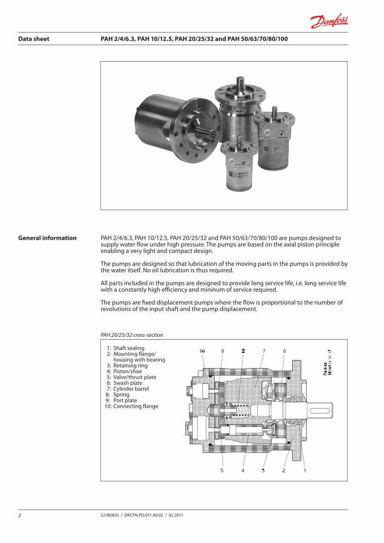
General information PAH 2/4/6.3, PAH 10/12.5, PAH 20/25/32 and PAH 50/63/70/80/100 are pumps designed to supply water flow under high pressure. The pumps are based on the axial piston principle enabling a very light and compact design.
The pumps are designed so that lubrication of the moving parts in the pumps is provided by the water itself. No oil lubrication is thus required.
All parts included in the pumps are designed to provide long service life, i.e. long service life with a constantly high efficiency and mininum of service required.
The pumps are fixed displacement pumps where the flow is proportional to the number of revolutions of the input shaft and the pump displacement.
PAH 20/25/32 cross-section
1: Shaft sealing 2: Mounting flange/ housing with bearing 3: Retaining ring 4: Piston/shoe 5: Valve/thrust plate 6: Swash plate 7: Cylinder barrel 8: Spring 9: Port plate10: Connecting flange
Data sheet PAH 2/4/6.3, PAH 10/12.5, PAH 20/25/32 and PAH 50/63/70/80/100
3521B0835 / DKCFN.PD.011.A9.02 / 02.2011
Features
Technical data
Application examples
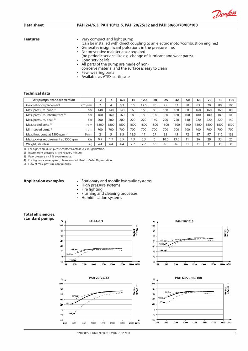
Total efficiencies, standard pumps
• Verycompactandlightpump (can be installed with direct coupling to an electric motor/combustion engine.)• Generatesinsignificantpulsationsinthepressureline.• Nopreventivemaintenancerequired (no periodic service like e.g. change of lubricant and wear parts).• Longservicelife• Allpartsofthepumparemadeofnon- corrosive material and the surface is easy to clean• Fewwearingparts• AvailableasATEXcertificate
• Stationaryandmobilehydraulicsystems• Highpressuresystems• Firefighting• Flushingandcleaningprocesses• Humidificationsystems
1) For higher pressure, please contact Danfoss Sales Organization. 2) Intermittent pressure is <10 % every minute. 3) Peak pressure is <1 % every minute. 4) For higher or lower speed, please contact Danfoss Sales Organization. 5) Flow at max. pressure continuously.
PAH pumps, standard version 2 4 6.3 10 12.5 20 25 32 50 63 70 80 100
Geometricdisplacement cm3/rev. 2 4 6.3 10 12.5 20 25 32 50 63 70 80 100Max. pressure. cont. 1) bar 140 140 140 160 160 80 160 160 80 160 160 160 80Max. pressure. intermittent 2) bar 160 160 160 180 180 100 180 180 100 180 180 180 100Max. pressure. peak 3) bar 200 200 200 220 220 140 220 220 140 220 220 220 140Max. speed cont. 4) rpm 1800 1800 1800 1800 1800 1800 1800 1800 1800 1800 1800 1800 1500Min. speed cont. 4) rpm 700 700 700 700 700 700 700 700 700 700 700 700 700Max. flow. cont. at 1500 rpm 5) l/min 2 5 8.5 13.5 17 27 35 45 72 87 97 112 138Max. power requirement at 1500 rpm kW 0.9 1.7 2.5 4.3 5.3 5 10.5 13.5 11 26 29 33 25Weight, stainless kg 4.4 4.4 4.4 7.7 7.7 16 16 16 31 31 31 31 31
PAH 20/25/32 PAH 63/70/80/100
PAH 4/6.3 PAH 10/12.5
Data sheet PAH 2/4/6.3, PAH 10/12.5, PAH 20/25/32 and PAH 50/63/70/80/100
4 521B0835 / DKCFN.PD.011.A9.02 / 02.2011
Suction pressure
Temperature
Shaft load
Noise level
Filtration
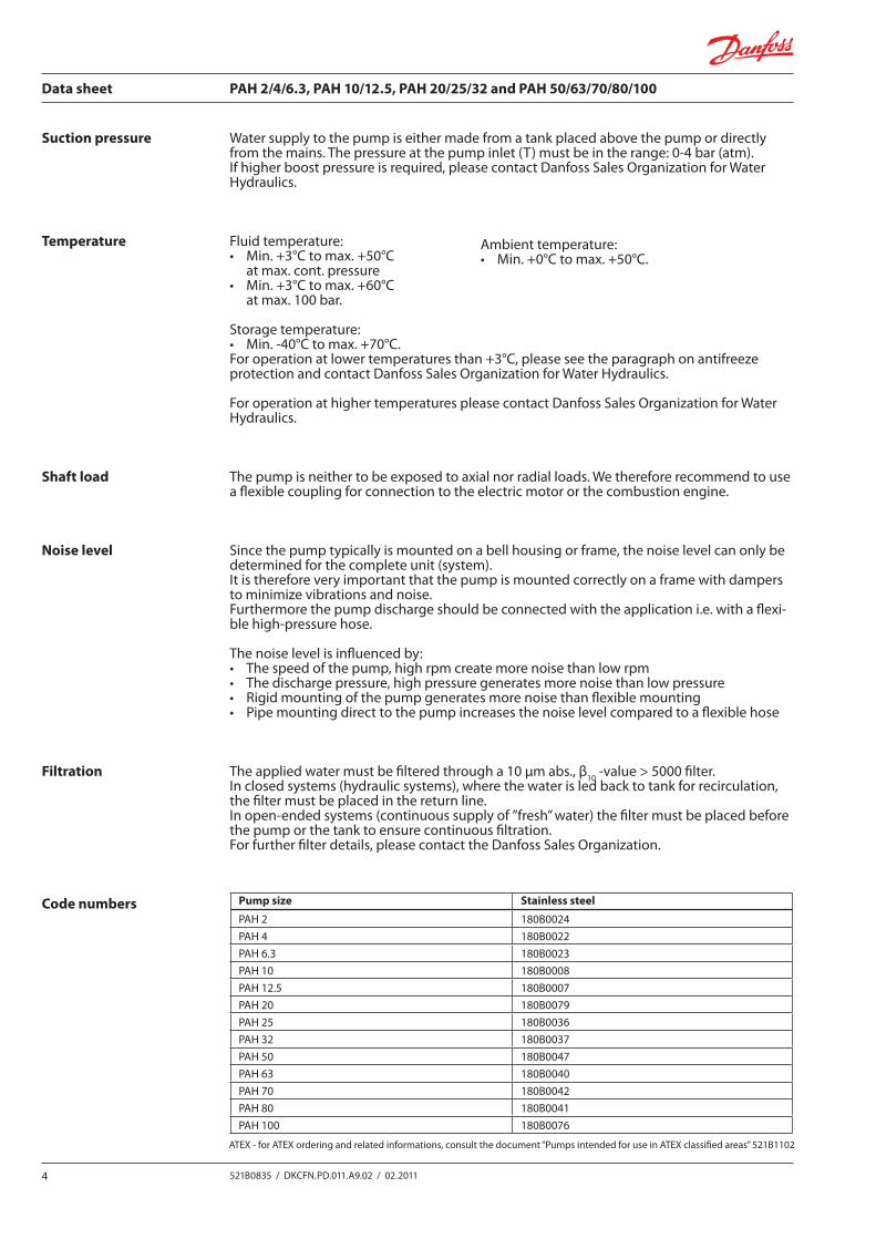
Code numbers
Water supply to the pump is either made from a tank placed above the pump or directly fromthemains.Thepressureatthepumpinlet(T)mustbeintherange:0-4bar(atm).If higher boost pressure is required, please contact Danfoss Sales Organization for Water Hydraulics.
Fluid temperature:• Min.+3°Ctomax.+50°C at max. cont. pressure• Min.+3°Ctomax.+60°C at max. 100 bar.
Storage temperature:• Min.-40°Ctomax.+70°C.Foroperationatlowertemperaturesthan+3°C,pleaseseetheparagraphonantifreezeprotection and contact Danfoss Sales Organization for Water Hydraulics.
For operation at higher temperatures please contact Danfoss Sales Organization for Water Hydraulics.
The pump is neither to be exposed to axial nor radial loads. We therefore recommend to use a flexible coupling for connection to the electric motor or the combustion engine.
Since the pump typically is mounted on a bell housing or frame, the noise level can only be determined for the complete unit (system). It is therefore very important that the pump is mounted correctly on a frame with dampers to minimize vibrations and noise. Furthermore the pump discharge should be connected with the application i.e. with a flexi-blehigh-pressurehose.
The noise level is influenced by:• Thespeedofthepump,highrpmcreatemorenoisethanlowrpm• Thedischargepressure,highpressuregeneratesmorenoisethanlowpressure• Rigidmountingofthepumpgeneratesmorenoisethanflexiblemounting• Pipemountingdirecttothepumpincreasesthenoiselevelcomparedtoaflexiblehose
The applied water must be filtered through a 10 µm abs., β10-value>5000filter.In closed systems (hydraulic systems), where the water is led back to tank for recirculation, the filter must be placed in the return line.Inopen-endedsystems(continuoussupplyof”fresh”water)thefiltermustbeplacedbeforethe pump or the tank to ensure continuous filtration.For further filter details, please contact the Danfoss Sales Organization.
Ambient temperature:• Min.+0°Ctomax.+50°C.
Pump size Stainless steel
PAH 2 180B0024PAH 4 180B0022PAH 6.3 180B0023PAH 10 180B0008PAH 12.5 180B0007PAH 20 180B0079PAH 25 180B0036 PAH 32 180B0037PAH 50 180B0047PAH 63 180B0040PAH 70 180B0042PAH 80 180B0041PAH 100 180B0076
ATEX-forATEXorderingandrelatedinformations,consultthedocument“PumpsintendedforuseinATEXclassifiedareas”521B1102
Data sheet PAH 2/4/6.3, PAH 10/12.5, PAH 20/25/32 and PAH 50/63/70/80/100
5521B0835 / DKCFN.PD.011.A9.02 / 02.2011
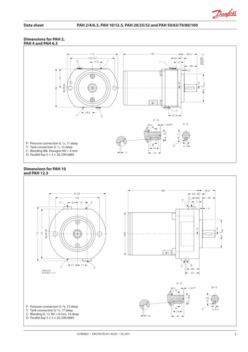
Dimensions for PAH 2, PAH 4 and PAH 6.3
Dimensions for PAH 10 and PAH 12.5
P: PressureconnectionG1/4, 11 deepT: TankconnectionG1/2, 15 deepC: Bleeding M6, Hexagon NV = 4 mmD: Parallel key 5 × 5 × 20, DIN 6885
P: PressureconnectionG3/8, 15 deepT: TankconnectionG3/4, 17 deepC: BleedingG1/4, NV = 6 mm, 14 deepD: Parallel key 5 × 5 × 20, DIN 6885
Data sheet PAH 2/4/6.3, PAH 10/12.5, PAH 20/25/32 and PAH 50/63/70/80/100
6 521B0835 / DKCFN.PD.011.A9.02 / 02.2011
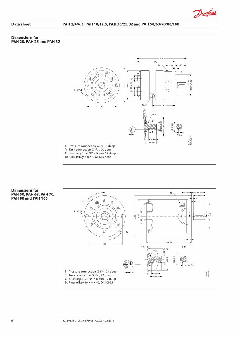
Dimensions for PAH 20, PAH 25 and PAH 32
P: PressureconnectionG3/4, 16 deepT: TankconnectionG11/4, 20 deepC: BleedingG1/4, NV = 6 mm, 12 deepD: Parallel key 8 × 7 × 32, DIN 6885
Dimensions for PAH 50, PAH 63, PAH 70, PAH 80 and PAH 100
P: PressureconnectionG11/4, 23 deepT: TankconnectionG11/2, 23 deepC: BleedingG1/4, NV = 6 mm, 12 deepD: Parallel key 10 × 8 × 45, DIN 6885
2 x Ø14
2 x Ø18
Data sheet PAH 2/4/6.3, PAH 10/12.5, PAH 20/25/32 and PAH 50/63/70/80/100
7521B0835 / DKCFN.PD.011.A9.02 / 02.2011
Installation
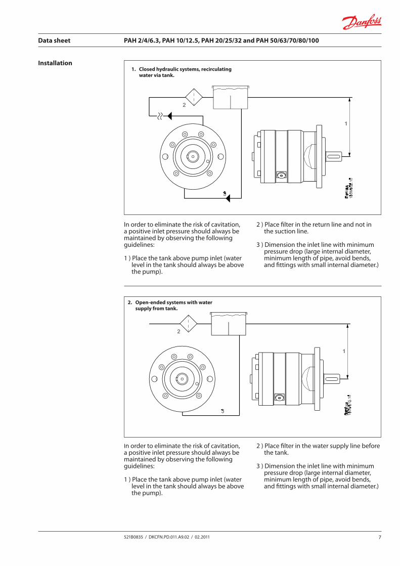
In order to eliminate the risk of cavitation, a positive inlet pressure should always be maintained by observing the following guidelines:
1 ) Place the tank above pump inlet (water level in the tank should always be above
the pump).
2 ) Place filter in the return line and not in the suction line.
3 ) Dimension the inlet line with minimum pressure drop (large internal diameter, minimum length of pipe, avoid bends,
and fittings with small internal diameter.)
1. Closed hydraulic systems, recirculating water via tank.
2. Open-ended systems with water supply from tank.
In order to eliminate the risk of cavitation, a positive inlet pressure should always be maintained by observing the following guidelines:
1 ) Place the tank above pump inlet (water level in the tank should always be above
the pump).
2 ) Place filter in the water supply line before the tank.
3 ) Dimension the inlet line with minimum pressure drop (large internal diameter, minimum length of pipe, avoid bends,
and fittings with small internal diameter.)
Data sheet PAH 2/4/6.3, PAH 10/12.5, PAH 20/25/32 and PAH 50/63/70/80/100
8 521B0835 / DKCFN.PD.011.A9.02 / 02.2011
M
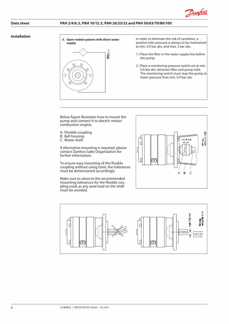
In order to eliminate the risk of cavitation, a positive inlet pressure is always to be maintained at min. 0.9 bar abs. and max. 5 bar abs.
1 ) Place the filter in the water supply line before the pump.
2 ) Place a monitoring pressure switch set at min. 0,9 bar abs. between filter and pump inlet. The monitoring switch must stop the pump at lower pressure than min. 0.9 bar abs.
3. Open-ended systems with direct water supply
Installation
Below figure illustrates how to mount the pump and connect it to electric motor/combustion engine.
A: Flexible couplingB: Bell housingC: Motor shaft
If alternative mounting is required, please contact Danfoss Sales Organization for further information.
To ensure easy mounting of the flexible coupling without using tools, the tolerances must be dimensioned accordingly.
Make sure to observe the recommended mounting tolerances for the flexible cou-pling used, as any axial load on the shaft must be avoided.
Data sheet PAH 2/4/6.3, PAH 10/12.5, PAH 20/25/32 and PAH 50/63/70/80/100
9521B0835 / DKCFN.PD.011.A9.02 / 02.2011
Water quality regarding purity and chemical/microbiological composition depends on the origin of the water as described below.
Water quality for hydraulic systems is recommended to be of at least the same quality as is required for drinking water. Classification of water:Water used in tap water hydraulic systems may typically be classified into 3 main groups:
A) Raw waterRaw water is most often water collected directly from borings & wells. Usually, water is expo-sedtoa”simple”process,suchasfiltration.Thequalityofrawwatermayvaryalot.Insomecases/places it is almost of drinking water quality, whereas water in other cases/ places may contain large amounts of ochre, humus & plant remnants .
Therefore, it is most important to analyse raw water intended for a certain application. Typical applications where raw water can be used are:
• Fire-fightingequipment• Highpressurecleaner
The filter capacity is an important parameter for these applications, as the water may con-tain large amounts of particles, sand, ochre etc.
B) Drinking waterDrinking water is exposed to a much more complex cleaning process compared to raw water. Drinking water is either produced on basis of ground water or surface water (rivers and lakes). Localauthoritiesareinchargeofcontrollingthewaterquality.
Ground Water:The quality of ground water is normally very fine and thus only minimum of processing is required. Typically, only filtration and ventilation is applied to remove aggressive carbon dioxide, iron and manganese.
Surface Water (Lakes and Rivers):In addition to the above process for ground water, it is essential to disinfect and process thiswaterfurther,assurfacewateriseitherchemicallyormicro-biologicallycontaminated.Typically, compounds of chlorine are used to disinfect the water which may give the drinkingwaterthecharacteristicafter-tasteofchlorine.Furthermore,UV-lightmaybeusedtosubstituteorsupplementthechlorineprocessing.
NB! Alwaysusedrinkingwaterfromthecold-watertaptominimizetheriskofmicrobiologicalcontamination of the water.
C) Technical WaterTechnical water may be divided into 3 groups:
• Softenedwater(cationexchanged).• Demineralizedwater (Demineralized/de-ionizedwater)• Waterprocessedaccordingtothereverseosmosisprinciple(RO-water)
Softened*anddemineralized*waterarenottobeusedfordrinkingwaterinmostEuro-pean countries as the chemicals used for the processes are harmful/hazardous to human beings .
*only applying to units being regenerative.
Descriptions of the specific processes are always enclosed the systems for making softened, de-mineralizedandreverseosmosis-water.
When using other fluids like HFA, HFC etc., please contact Danfoss Sales Organization.
Pumps for Technical water are listed in a separate Data sheet
Water
Data sheet PAH 2/4/6.3, PAH 10/12.5, PAH 20/25/32 and PAH 50/63/70/80/100
10 521B0835 / DKCFN.PD.011.A9.02 / 02.2011
Antifreeze protection
Tank
Direction of rotation
Ifasystemrequiresantifreezeprotection,DanfossrecommendsDOWCALNorCHILLSAFEantifreezesbothbeingabiologicallydegradableMonoPropyleneGlycol.
(DOWCALNisproducedbyPOLO).(CHILLSAFEisproducedbyATCO).ProducersofDOWCALNandCHILLSAFErecommendamixtureratioofmin.30%DOWCALN/CHILLSAFEtopreventbiofilmoccurrenceinthesystemduetoDOWCALNandCHILLSAFEbeingbiologicallyde-gradable.
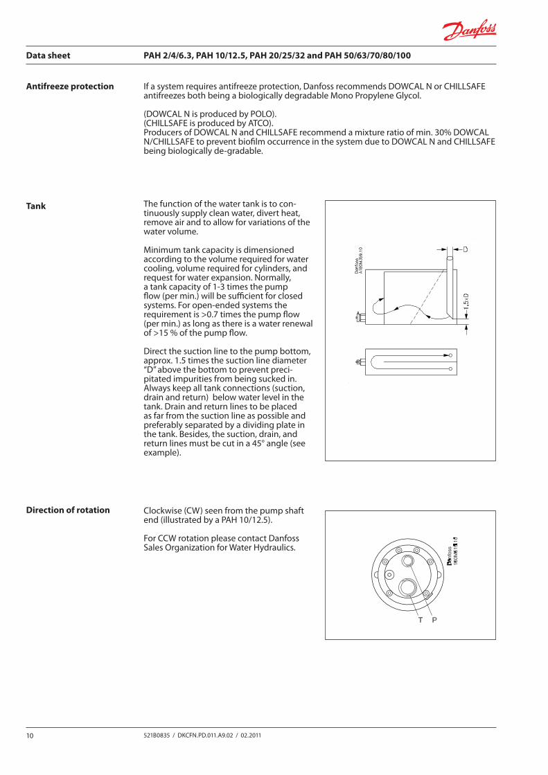
The function of the water tank is to con-tinuously supply clean water, divert heat, remove air and to allow for variations of the water volume.
Minimum tank capacity is dimensioned according to the volume required for water cooling, volume required for cylinders, and request for water expansion. Normally, atankcapacityof1-3timesthepumpflow (per min.) will be sufficient for closed systems.Foropen-endedsystemstherequirementis>0.7timesthepumpflow(per min.) as long as there is a water renewal of>15%ofthepumpflow.
Direct the suction line to the pump bottom, approx. 1.5 times the suction line diameter “D”abovethebottomtopreventpreci-pitated impurities from being sucked in. Always keep all tank connections (suction, drain and return) below water level in the tank. Drain and return lines to be placed as far from the suction line as possible and preferably separated by a dividing plate in the tank. Besides, the suction, drain, and returnlinesmustbecutina45°angle(seeexample).
Clockwise (CW) seen from the pump shaft end (illustrated by a PAH 10/12.5).
For CCW rotation please contact Danfoss Sales Organization for Water Hydraulics.
Data sheet PAH 2/4/6.3, PAH 10/12.5, PAH 20/25/32 and PAH 50/63/70/80/100
11521B0835 / DKCFN.PD.011.A9.02 / 02.2011
Disconnection:IftheinletlinetothepumpT-portisdiscon-nected from the water supply, the pump will be emptied of water.Before starting the pump again, the starting proceduredescribedintheStart-upparagraphmust be followed.
Transport and Storage PrecautionsIf emptied of water, the system must be pro-tected against corrosion with a glycol mixture (minimum 35% monopropylene glycol).
The protection must be made within 2 days after the emptying.
If there is risk of exposure to temperatures below the freezing point during transport or storage, the system likewise has to be flushed with a glycol mixture (minimum 35% monopropylene glycol).
Forfurtherinformationonanti-freezemedia,please contact Danfoss Sales Organization.
Recommended procedure:1. Closed hydraulic systems with recirculating
waterandopen-endedsystemswithwatersupply from tank:
1.1 Emptythesystemofwater 1.2 Fill glycol mixture onto the system through
a 10 µm abs. filter 1.3 Start up the system. Remember to bleed
the pump, if required. 1.4 Required functions are activated to be
flushed with the glycol mixture 1.5 Surplus glycol is emptied off the system 1.6 The pump is now protected against
internal corrosion and frost.
2. Open-endedsystemswithdirectwatersupply: 2.1 Disconnect the water supply to the pump/system.
2.2 Emptythepumpthroughthelower bleeding plug. Retighten the plug when the pump is empty.
2.3 Connectthepumptoatankwithanti- freeze additive. Connect a hose to the pumpP-portandtheotherendofthe hose back to tank.
2.4 Quickly start and stop the pump. Make sure that the pump does not run
dry. 2.5 Emptypumpofanti-freezemedium
(through the lower bleeding plug). Remount and retighten the bleeding plug, when the pump is empty.
2.6 The pump is now protected against internal corrosion and frost.
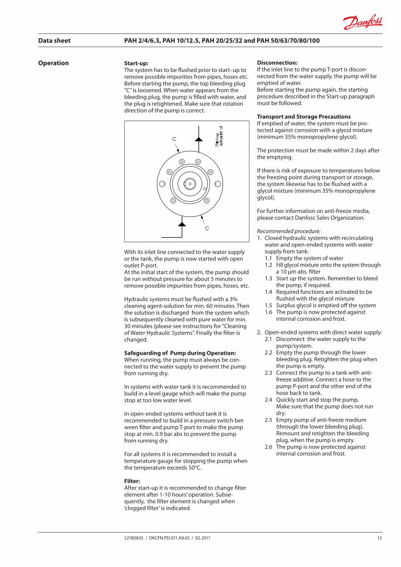
Start-up: The system has to be flushed prior to start–up to remove possible impurities from pipes, hoses etc.Before starting the pump, the top bleeding plug ”C”isloosened.Whenwaterappearsfromthebleeding plug, the pump is filled with water, and the plug is retightened. Make sure that rotation direction of the pump is correct.
With its inlet line connected to the water supply or the tank, the pump is now started with open outletP-port.At the initial start of the system, the pump should be run without pressure for about 5 minutes to remove possible impurities from pipes, hoses, etc.
Hydraulic systems must be flushed with a 3% cleaningagent-solutionformin.60minutes.Thenthe solution is discharged from the system which is subsequently cleaned with pure water for min. 30minutes(pleaseseeinstructionsfor”CleaningofWaterHydraulicSystems”.Finallythefilterischanged.
Safeguarding of Pump during Operation:When running, the pump must always be con-nected to the water supply to prevent the pump from running dry.
In systems with water tank it is recommended to build in a level gauge which will make the pump stop at too low water level.
Inopen-endedsystemswithouttankitisrecommended to build in a pressure switch bet-weenfilterandpumpT-porttomakethepumpstop at min. 0.9 bar abs to prevent the pump from running dry.
For all systems it is recommended to install a temperature gauge for stopping the pump when thetemperatureexceeds50°C.
Filter:Afterstart-upitisrecommendedtochangefilterelementafter1-10hours’operation.Subse-quently, the filter element is changed when ‘cloggedfilter’isindicated.
Operation
Data sheet PAH 2/4/6.3, PAH 10/12.5, PAH 20/25/32 and PAH 50/63/70/80/100
12 521B0835 / DKCFN.PD.011.A9.02 / 02.2011
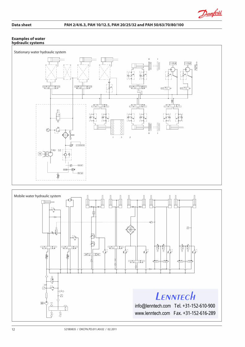
Examples of waterhydraulic systems
Stationary water hydraulic system
Mobile water hydraulic system
[email protected] Tel. +31-152-610-900www.lenntech.com Fax. +31-152-616-289