Embed Size (px)
Citation preview
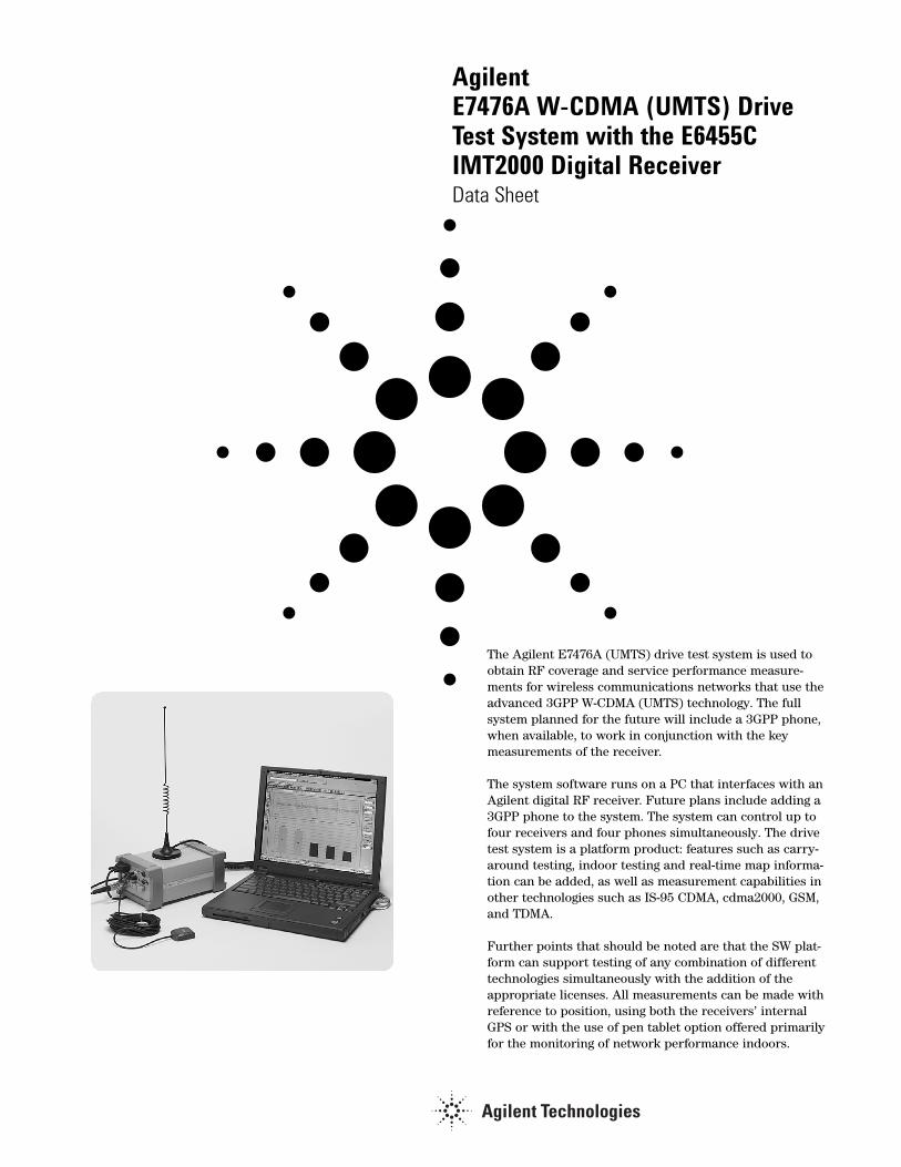
Agilent E7476A W-CDMA (UMTS) DriveTest System with the E6455CIMT2000 Digital ReceiverData Sheet
The Agilent E7476A (UMTS) drive test system is used toobtain RF coverage and service performance measure-ments for wireless communications networks that use theadvanced 3GPP W-CDMA (UMTS) technology. The full system planned for the future will include a 3GPP phone,when available, to work in conjunction with the key measurements of the receiver.
The system software runs on a PC that interfaces with anAgilent digital RF receiver. Future plans include adding a3GPP phone to the system. The system can control up tofour receivers and four phones simultaneously. The drivetest system is a platform product: features such as carry-around testing, indoor testing and real-time map informa-tion can be added, as well as measurement capabilities inother technologies such as IS-95 CDMA, cdma2000, GSM,and TDMA.
Further points that should be noted are that the SW plat-form can support testing of any combination of differenttechnologies simultaneously with the addition of theappropriate licenses. All measurements can be made withreference to position, using both the receivers’ internalGPS or with the use of pen tablet option offered primarilyfor the monitoring of network performance indoors.

2
System software
The system software controls Agilent digital RFreceivers, and eventually will be used as a common platform to control W-CDMA (UMTS) mobile phones.Multiple measurements can be made simultaneously. Allmeasurements can be displayed in real-time and loggedto the database with reference to position. Three systemsoftware options are available:
• Option 110: W-CDMA receiver-based software license• Option 160: Real time mapping software license• Option 180: Indoor measurement software license
Receiver-based softwareThe receiver measurement functions of the AgilentE7476A system are provided by Option 110. This option,combined with the E6455C digital receiver option, is composed of four primary elements:
• W-CDMA (UMTS) scrambling code analysis• Spectrum analysis• CW power with external trigger• Channel power
Each element has an associated control and display win-dow called a virtual front panel (VFP). The software cancontrol up to four Agilent E6455C digital receivers forsimultaneous monitoring of up to four 5 Mhz bands. Thecontrols listed below are available for the receiver meas-urements:
• Measurement interval❑ Time❑ Distance
• Averaging (spectrum, CW, and channel power only)❑ Running❑ Group❑ Max hold❑ At least (CW and channel power only)
The measurement interval defines the duration betweenmeasurements. This can be specified in terms of time(execute a measurement every 200 milliseconds), or distance (execute a measurement every 10 meters).
There are two ways to define the interval by distance.One is with the use of the GPS and the other is by usingthe external trigger capability. If the user defines aninterval that the system can not achieve, a busy lightindicates this condition.
W-CDMA (UMTS) scrambling code analysisThe Agilent E7476A system measures 3GPP W-CDMA(UMTS) physical layer. The system makes absolute andrelative power measurements of the primary sync chan-nel, secondary sync channel and the scrambling codes(CPICH). These measurements are independent of net-work parameter settings. The system executes three dif-ferent types of W-CDMA (UMTS) scrambling code meas-urements (listed below). Any or all of them can be execut-ed simultaneously and in conjunction with other typesof measurements, such as spectral analysis.
Measurement types• Primary
SCH scan: The system measures the power in either Ec and Ec/Io and Eb/Io of Each Primary SCH. The results are displayed as a trace that shows the power for each primary synchroniza-tion channel detected in one timeslot of2560 chips. Exported data has Ec, Ec/Io, and Eb/Io available.
• Top N: The system measures all of the scrambling codes in a timeslot of 2560 chips and returns the ‘N’ strongest scrambling codes received, where ‘N’ is a user definable integer from 1 to 20. The sensitivity can be varied by aver-aging over several time slots. The results are displayed in a bar graph format. (The primary sync and second-ary sync are also measured as part of the Top N measurement and can be displayed on top of each bar in the bargraph).
• User list: The user manually inputs a list of up to 40 scrambling codes to be measured. It should be noted that this measurement only correlates the codes chosen by the user and does notprocess any sync channel information.

3
Measurement controls• Carrier frequency
❑ Frequency
❑ Channel
• Measurement types
❑ All sync channels
❑ Top N
❑ User list
• Sync channel decode
Display controls• Power display (Y-axis parameter)
❑ Ec/Io (alternatively Eb/Io)
❑ Ec (alternatively Ec/Io)
Top N measurements and show value❑ Primary sync code power Ec
❑ Primary sync code power Ec/Io
❑ Scrambling code group
❑ Secondary sync code
❑ Secondary sync code Ec
❑ Secondary sync code Ec/Io
❑ Scrambling code peak Ec
❑ Scrambling code peak Ec/Io
❑ Scrambling code peak Eb/Io
❑ Scrambling code aggregate Ec
❑ Scrambling code aggregate Ec/Io
❑ Scrambling code aggregate – peak
❑ Scrambling code delay spread
❑ Scrambling code time offset
❑ SSCH – PSCH
❑ SC – PSCH
Markers (trace displays only)• Multiple markers
• Delta markers
• To max function
• Drag and drop
Measurement results• Io
• Primary sync channel
• Primary sync channel Ec
• Primary sync channel Ec/Io
• Primary sync channel Eb/Io
• Carrier frequency error
• Time stamp
Top N and user list and show value• Scrambling code
• Scrambling code peak Ec
• Scrambling code peak Ec/Io
• Scrambling code peak Eb/Io
• Relative time
• Scrambling code aggregate Ec
• Scrambling code aggregate Ec/Io
• Scrambling code aggregate Eb/Io
• Scrambling code aggregate – peak power
• Delay spread
Notes: Instead of Ec/Io values, Eb/Io values may be displayed. The scrambling code can be displayed in decimal or hexadecimal format.

4
Measurement methodologies and definitions
In Top N measurements scrambling code peak power (Ec, Ec/Io and Eb/Io) is computed by following the following sequence:
By averaging over a user defined number of Timeslotsand selecting the strongest signal of the visible. Thevalue of the associated secondary sync is then correlat-ed for power and the secondary sync sequence isachieved to determine the scrambling code group. Thescrambling code (or codes) variables are then deter-mined from within this group. This is repeated for allvalues of primary syncs above the pre-determinedthreshold.
Io is the total received power integrated across theentire 3.84 MHz signal bandwidth.
Scrambling code aggregate power (Ec, Ec/Io, Eb, and Eb/Io) is computed for a given scrambling code by integratingthe power received over the time dispersion of thatscrambling code.
User List Ec, Ec/Io, Eb/Io is calculated by correlating theenergy attributed to the user defined scrambling code.This is calculated directly and does not use the syncchannel.
Delay spread is the duration of time over which thispower is dispersed. Both aggregate power and delayspread are determined with respect to an Ec/Io thresh-old of –17 dB. The system also reports the differencebetween the aggregate and peak power (aggregate –peak). This difference along with the delay spread pro-vides a characterization of the multipath effect on thatscrambling code. Aggregate power and delay spread areonly measured for the Top N and user list measurementtypes.
Relative time is defined as the difference in time betweenwhen a scrambling code signal is received relative to thestart of the 2560 chip timeslot as arbitrarily defined inthe receiver. For example, the receiver will arbitrarilyrecord a 2560 chip sequence where the beginning of thissequence is defined as zero time. Each scrambling codewill have some delay from this start and thus will have arelative time to the start of the time defined in thereceiver.
Carrier frequency error is defined as the difference betweenthe measured carrier frequency and the user-specified car-rier frequency. Carrier frequency error can be due to bothbase station carrier error and doppler shift (if moving).
Figure 1. Scrambling code VFP

5
Scrambling code measurements. (Typical/characteristic performance measures:)
General parameter thresholds for the Top N measure-ment with no other VFPs open.
1.Each primary sync with Ec/Io greater than the noise threshold which equals –21.5 dB for greater than12 timeslots, will be processed.
2.Each and every associated secondary sync, with Ec/Io greater than the noise which equals –21.5 dB forgreater than 12 timeslots, will be processed. There canbe multiple secondary syncs per each primary sync.
3.For every secondary sync that is processed, any and all scrambling codes within that group, of amplitude greater than –20.5 dB, will be reported.
4.If no scrambling code can be detected under a processed secondary sync, then the group alone will be reported, if the secondary sync’s Ec/Io value is greater than –17 dB.
General parameter thresholds for the user list measurement with no other VFPs open.
The user list measurement does not use any aspect ofthe synchronization channel. The noise threshold forreliable measurements of Ec/Io is –18.5 dB.
Table 1. Top N measurements approximate update rates with 16 timeslot averaging:
Top N with primary sync Without carrier tracking (ms) With carrier tracking (ms)
1 SC Present 570 640
2 SC present 590 660
3 SC present 610 680
8 SC Present 710 780
N SC Present 550 + 20N 620 + 20N
Table 2. Top N dynamic range with variable timeslots:
Top N With primary sync # Timeslots Process synchronization Report scrambling
channel above (dB) codes above (dB)
“ 3 –17.0 –20.5
“ 8 –19.5 –20.5
“ 16 –21.5 –20.5
Table 3. User list measurement approximate update rates:User list only # Scrambling codes Without carrier tracking (ms) With carrier tracking (ms)
“ 1 700 770
“ 5 1500 1570
“ 10 2500 2560
“ L>10 approximately 500 + 200L approximately 570 + 200L
Note:This information represents typical or characteristic aspects of the measurement and is not specified (tested on the pro
duction line) nor warranted. Agilent Technologies reserves the right to change the measurement algorithm, at it’s discretion,
to improve performance or to fix defects.

6
Spectrum analysis The spectrum display provides the controls listed below.Frequencies can be specified in terms of frequency unitsor channel number.
Measurement controls• Frequency, tunable range
1
❑ IMT 2000 receiver (Option 360 or 361)
–1920 – 1980 MHz [1895 – 1990]
–2110 – 2170 MHz [2100 – 2180]
• Frequency, maximum span1
❑ IMT 2000receiver (Option 360 or 361)
–60 MHz [70]
• IF bandwidth
❑ 1.25 MHz
❑ 5 MHz
• Resolution bandwidth
❑ 8.36 kHz to 1 MHz (with 1.25 MHz IF bandwidth)
❑ 25.08 kHz to 2.85 MHz (with 5MHz IF bandwidth)
• Average mode
❑ Log power❑ Power
Markers• Multiple markers
• Delta markers
• Marker to max
• Marker value to center frequency
• Drag and drop
Spectrum noise floor (characteristic)2:Average Peak
1.25 MHz IF bandwidth / 1 MHz span –127 dBm –118 dBm
5.0 MHz IF bandwidth / 1 MHz span –123 dBm –113 dBm
1.25 MHz IF bandwidth / 25 MHz span –123 dBm –117 dBm
5.0 MHz IF bandwidth / 25 MHz span –117 dBm –113 dBm
Minimum sweep speed (characteristic)2:
1.25 MHz IF bandwidth 70 MHz / sec
5.0 MHz IF bandwidth 200 MHz / sec
1 Spectrum measurement allows tuning ±10 MHz above and below specified frequency ranges. In addition the Japan PHS band is also covered
(down to 1895MHz). The extended ranges are shown in brackets –[ ] The performance is not specified in these extended ranges. Characteristic
noise floor increase is 2 dB ±10 MHz. At –25MHz with respect to specified range, the characteristic noise floor increase is 5dB. Characteristic
amplitude accuracy is unchanged with respect to specified range.
2 Does not imply warranted performance, but rather characteristic performance. Tested with minimum resolution bandwidth: 8.36 kHz with 1.25 MHz
IF Bandwidth, 25.08 kHz with 5.0 MHz IF bandwidth.
Note:Specifications describe warranted performance over the temperature range of 0 to 55 °Celsius and include a 30 minute warm-up from ambient
conditions. Typical and characteristic information provides useful but non-warranted performance parameters. Typical refers to test data at the fiftieth
percentile for a 25 °Celsius room temperature. Characteristic information describes product information for parameters that are either not subject
to variation, non-measurable, verifiable through functional pass/fail tests, or routinely not measured.
Figure 2. Spectrum Analysis VFP

7
CW power and channel power The Agilent E7476A can measure the peak power (CWpower) at user-defined frequencies within a user-definedresolution bandwidth. The systems can also measure thetotal power (channel power) within a user-definedbandwidth at a user-defined set of frequencies. Channelpower differs from the CW power measurement in thatthe total power is integrated across the specified chan-nel width. The user can define the frequencies measuredin two different ways, indicated below.
Frequency entry methods• List: Enter an arbitrary list of frequencies.
• Trace: Enter a start frequency, step size, and count. The system measures at the start frequency, at the (start + step) frequency, ... , (start + (count - 1)*step) frequency. For example, if the start frequency is set to 1900 MHz, the step size is set to 1 MHz, and the count is set to 4; then measurements are made at 1900 MHz, 1901 MHz, 1902 MHz and 1903MHz.
Frequencies can be specified in terms of frequency unitsor channel number.
External pulse triggering is used for precise distancemeasurements by using pulses sent from the vehiclespeed sensor to detect how far the vehicle has traveled.A maximum pulse rate of 3,333 pulses/ second with aminimum pulse width of 100 ns can be measured. (At 1pulse per centimeter, this would correspond to a speedof approximately 120 km/hour). The maximum TTL volt-age is 15 volts and triggering is on the negative edge ofthe pulse.
Measurement controls• Frequency
❑ Arbitrary list (list)❑ Start / step / count (trace)
• IF bandwidth ❑ 1.25 MHz❑ 5.0 MHz
• Resolution bandwidth (CW power only)❑ 8.36 kHz to 1 MHz (with 1.25 MHz IF bandwidth)❑ 25.08 kHz to 2.85 MHz (with 5.0 MHz IF
bandwidth)• Channel width (channel power only)
❑ IMT 2000 receiver (Option 300 or 301)–30 kHz to 80 MHz (with 1.25 MHz IF bandwidth)–100 kHz to 80 MHz (with 5.0 MHz IF bandwidth)
• Measurement interval❑ Time❑ Distance
• GPS• External pulse triggering
Note:Specifications describe warranted performance over the temperature range of 0 to 55 °Celsius and include a 30 minute warm-up from ambient
conditions. Typical and characteristic information provides useful but non-warranted performance parameters. Typical refers to test data at the
fiftieth percentile for a 25 °Celsius room temperature. Characteristic information describes product information for parameters that are either not
subject to variation, non-measurable, verifiable through functional pass/fail tests, or routinely not measured.
Figure 3. Power VFP

8
Alerts and alarmsThe Agilent E7476A has sophisticated alarm capabilities.An alert is defined as a single condition on a singlemeasurement. An alarm is a boolean expression madeup of multiple conditions on multiple measurements. Ifthe alert or alarm condition occurs while data is beinglogged, each data record includes the alert and alarminformation.
The alarm wizard provides fast, easy setup of commonlyused alarms. The alarms available for W-CDMA (UMTS)via the wizard are listed below.
• No coverage • Weak CW • Lost GPS fix • No location fix • Low disk space • Low battery • No AC power• High CPU usage• Pilot pollution
When an alert or alarm condition occurs, any or all ofthe actions listed below can be executed.
Actions• Play a .wav audio file• Display a text message• Pause or stop measurements
Alert operators• Value• Maximum• Minimum
Alarm operators• Value• Maximum• Minimum• Sub-set• OR• AND• XOR (exclusive OR)
Alert conditions• Greater than (>)• Greater than or equal to (≥)• Less than (<)• Less than or equal to (≤)• Equal to (=)• Not equal to (≠)
Alarm conditions• Greater than (>)• Greater than or equal to (≥)• Less than (<)• Less than or equal to (≤)• Equal to (=)• Not equal to (≠)• Is a sub-set• Is not a sub-set• Sets intersect• Sets do not intersect
Any measurement can be an operand in an alert oralarm. Below are some examples to illustrate alerts andalarms.
Alerts: 1. Value (primary SCH Io) < – 85 dBm2. Max (scrambling code Top N) < –10 dB
Alarms: 3. (Value (primary SCH Io) < – 85 dBm) AND(Max (scrambling code Top N) < –10 dB)
System status parameters can also be used as operands inalerts and alarms. For example, an alert can be defined totrigger when the available disk space on the PC dropsbelow 10 MB or when the GPS position fix is lost.
System status parameters• Available disk space• GPS fix• Location• Velocity• Percent CPU usage• PC battery level• PC AC power • Time of day

9
Data recording and playbackLogging of drives and playback of data are controlled byeasy to use buttons. While logging data, the user canenter notes into the data. Two methods of user noteentry are provided. One prompts the user to enter a textstring, for example, entering a tunnel. The other auto-matically enters a numbered note into the databaserequiring minimum interaction with the keyboard. Asummary of record and playback features are listedbelow.
Record features• User note• Automatically numbered note• Display on/off• Pause/resume• User-defined data set name
Playback features• Play forward• Play reverse• Step forward• Step reverse • Variable speed• Advance to alert/alarm• Advance to user note/auto-numbered note
Report generator and display printingThe Agilent E7476A provides fast and easy report genera-tion. All of the current displays (virtual front panels) arecaptured to an HTML file. Each report includes a headersection. After selecting generate report, a dialog boxprompts the user to enter the header information listedbelow. Smart defaults and persistent information areused, so minimal text entry is required.
Header elements• Title• User name• Company• Time • Date• Location – defaults to current GPS fix• Comments – user entered notes
There is no limit to the number of reports that can be generated. Reports can be generated during playback aswell as during live data collection.
Any virtual front panel can be printed by selecting theprint command from the file menu.

10
Data exportData can be exported from the Agilent E7476A databasefor display and post-processing. All measurement datacan be exported. The export function provides flexiblefiltering capability that defines the specific data to beexported. Multiple data types can be exported to a sin-gle output file.
The user can save export plans. Once an export plan hasbeen saved it can be retrieved to quickly and easilyexport the desired data. An export plan is made up of:
• Data type(s): Defines which data will beexported. Column order isuser definable.
• Alarms: Defines which alarms will be exported.
• Processing Defines the functions that functions: will be applied to the data
during export.
• Exclusion rules: Defines a set of conditions that, if true, the associated data will be excluded from the export.
• Geographic Data-reduction process in binning: which the data is averaged over
geographic area or distance.
Several different operations can be executed in order toprovide the desired data in the desired format.
Processing functions• All values• Count – counts number of values above or below a
specified threshold• Count with summary – same as count with a text file
summarizing the results• Maximum• Minimum• Value(x)
Conditionals• Greater than (>) a threshold• Less than (<) a threshold• All values• Qualified against another measurement
Sorting• Ascending• Descending• None
Geographic binning methods• Grid - drive area is overlaid by a grid of user-definable
size. The average of the data over each square is reported.• Linear distance – user defines a drive distance over
which to average. The average of the data over each segment of that distance is reported.
• None
The output formats supported by the Agilent E7476Aare listed below. The system is designed to work withMapInfo in an integrated manner via an object linkembedded (OLE) link to the MapInfo application. Thisexports the data, launches MapInfo, creates the neces-sary MapInfo tables, and creates a thematic map displayin MapInfo. This function requires MapInfo be present.MapInfo is not included with the E7476A system.
Data output formats• MapInfo OLE• MapInfo text file• ArcView text file• Plain text file (no headers)• PlaNET result (CW power data only)• Raw binary
RF receiver hardware
There is one digital RF receiver designed to work withthe Agilent E7476A system:
• E6455C: 2100 MHz IMT2000 receiver with internal GPS receiver
The Agilent E7476A system with Option 110 has softwarefunction for controlling the receivers. The system supports any combination of receivers from the Agilentdrive test family, up to a total of four. Using multiplereceiver configurations can greatly improve drive testefficiency for applications such as simultaneously moni-toring both uplink and downlink, and monitoring compet-itive networks. In multiple receiver configurations thereceivers communicate with each other via a high speedserial ring. Communication with the PC is done via asingle RS-232 link to one of the receivers in the ring.
It is also the case that multi-technology testing can beachieved by the use of GSM, CDMA, cdma2000, TDMAreceivers with addition of the necessary license up tothe maximum of four receivers of any technologies.
Each receiver option includes:• RF antenna for the corresponding frequency band• Cable to connect to other receivers• Cable to connect to PC• Kit for mounting receiver in a vehicle• AC/DC power supply• Cigarette lighter power cord• GPS antenna and cables

11
Agilent digital RF receiver specifications (E6455C)
FrequencyFrequency range1
Options 360, 361 1920-1980 MHz [1895 – 1990]2110-2170 MHz [2100 – 2180]
Frequency accuracy ± 1 ppmwith GPS time synchronization ± 0.05 ppm characteristic
IF bandwidth 1.25 MHz characteristic5 MHz characteristic
Aging of TCXO ± 1 ppm/year
AmplitudeAccuracy
1.25 MHz IF bandwidth ± 0.5 dB typical
from –25dBm to –110 dBm5 MHz IF bandwidth ± 0.5 dB typical from
–25dBm to –100 dBmNoise figure 8 dB typicalInternally generated
spurious, input referred –120 dBm for 1.25MHz
IF Bandwidth –115 dBm for 5MHz IF bandwidth
Maximum safe input level +10 dBm, 20V DC
characteristic1 dB compression
point 2 –15 dBm characteristicAdjacent channel
desensitization 3 –20 dBm typicalAdjacent channel rejection 4 25 dB typical
Input/outputRF input 50W type-NExternal trigger input BNC connector
ConnectorsComputer RS-232 (DB9) maleGPS RS-232 (DB9) malePower DC power jack 100 mils,
positive center
MiscellaneousOperating temperature range 0 to 55 °CMaximum relative humidity 80% for temperatures up to
31 °C, decreasing linearly to 50% relative humidity
at 40 °CStorage temperature range -40 to 70 °CDimensions 6 in x 3 5/8 in x 8 3/4 in
15.24 cm x 9.21 cm x 20.32 cmWeight 4.6 lbs. (2.1 kg)Power 9-34 V DC, 9Wwith Internal GPS (Option 301 and 311) 9-34 V DC, 10W
Internal GPSGPS receiver 8 channel internal GPS
receiverConnector type SMADifferential compatible without dead reckoning
1 Spectrum measurement allows tuning ±10 MHz above and below specified frequency ranges. In addition, the Japan PHS band is also covered
(down to 1895MHz). These extended ranges are shown in brackets – [ ]. The performance is not specified in these extended ranges. Characteristic
noise floor increase is 2 dB ±10 MHz. At –25MHz with respect to specified range, the characteristic noise floor increase is 5dB. Characteristic
amplitude accuracy is unchanged with respect to specified range.
2 It is recommended that the input signal level not exceed –40 dBm.
3 Adjacent channel desensitization applies to the 5.0 MHz IF filter and is defined as the 1 dB compression of tuned signal with interfering signal
±5.0 MHz from tuned signal.
4 Adjacent channel rejection applies to the 1.25 MHz IF filter and is defined as the Suppression of an interfering signal ±1.25 MHz from tuned signal.
Note:Specifications describe warranted performance over the temperature range of 0 to 55 °Celsius and include a 30-minute warm-up from ambient
conditions. Typical and characteristic information provide useful information by giving non-warranted performance parameters. Typical refers to
test data at the fiftieth percentile for a 25 °Celsius room temperature. Characteristic information describes product information for parameters that are
either not subject to variation, non-measurable, verifiable through functional pass/fail tests, or as a matter of routine not measured.

1212
GPS
The Agilent E7476A system has the ability to work withseveral types of GPS interfaces. The system is compati-ble with the communications protocols listed below. Thephysical interface is RS-232 with a DB9 connector.
Compatible protocols• TAIP• TSIP• NMEA
Internal GPS receiver• 8 channel GPS receiver• Mounted inside Agilent RF receiver enclosure• SMA antenna connector• Bulkhead mount antenna with cable• Magnetic mount antenna with cable• Differential compatible• Not dead reckoning compatible
The Agilent E7476A software includes a virtual frontpanel for the GPS receiver. This window displays a bargraph with the individual satellite signal strengths (TSIPprotocol only), a text display of the GPS statistics, and amap of location history. This map also displays the basestation locations and names.
GPS receiver model Interconnect requirementTrimble placer GPS/DR Option 211
Trimble placer GPS 455 Option 212
Trimble sveeSix Straight-through RS-232 cable
Trimble placer GPS 400 Straight-through RS-232 cable
Agilent 86154A Option 230: differential GPS receiver• Differential corrections, incorporated RDS-3000• Magnetic mount antenna• Interconnect cables
Two different GPS receiver configurations are availablefrom Agilent Technologies for our drive test systems1:
Agilent E7476A receiver Option 361 includes a GPSreceiver mounted inside the receiver enclosure. Thisconfiguration provides excellent portability and conven-ience.
Agilent 86154A Option 210 adds a Trimble Placer GPS455 receiver with dead reckoning for external connec-tion to the system.
Agilent 86154A Option 210• Trimble Placer GPS 455 with dead reckoning• Heading sensor • Interconnect adapter (to connect to the
Agilent RF receiver)• Interconnect cables• Bulkhead mount antenna with cable• Magnetic mount antenna with cable• Differential compatible
External GPS receivers communicate with the E7476Avia an RS-232 serial connection. The table below listsseveral GPS receiver models and the associated require-ments for connection to an E7476A system. For othermodels of external GPS receivers, consult an Agilentrepresentative for interconnect requirements.
If a GPS receiver is purchased from Agilent, all necessaryinterconnect parts are provided.
Differential GPS can be used with the Agilent E7476A systems, provided the GPS receiver being used is differen-tial compatible. Agilent 86514A Option 230 adds a dif-ferential GPS receiver to the system.
1 With the Agilent W-CDMA (UMTS) receiver with internal GPS (E7476A, Option 361), an external GPS source may be used with the receiver even
though an internal GPS exists within the receiver housing. This is valuable for differential or dead reckoning measurements that may be needed.
Note:Only one GPS source can be used at any given time.

13
Real-time mappingThe Agilent E7476A Option 160 software license pro-vides real-time data mapping. A single measurementparameter is plotted on the map, in color-coded themat-ic format, as the data is collected. Base station locationsare plotted on the map with site names, sector orienta-tions and PN offsets. Alarms are plotted on the map.Double clicking on the alarm symbol displays the corre-sponding alarm text message.
Measurement parameters that can be plotted on map• Scrambling code analysis (receiver)• Best server Ec/Io – from topN • Best server Ec/Io – from user list• Io – from topN• Io – from user list
• Carrier frequency• 4/CW and channel power• Max CW power list• Max CW power trace• Max channel power list• Max channel power trace
An indicator line is drawn from the current location tothe serving sector.
Measurement parameters that can represent servingsector• Scrambling code analysis (receiver)• Best server scrambling code – from topN• Best server scrambling code – from user list
The underlying map is in MapInfo .TAB format. The soft-ware can convert a raster image (.GIF or .TIF) to .TAB for-mat, so the user can use any map that is in .TAB, .GIF, or.TIF format.
E7476A software option 180 provides indoor measure-ment functionality. The indoor measurement virtualfront panel provides the ability to make phone based W-CDMA (UMTS) wireless measurements inside of build-ings. While walking through a building, waypoints arerecorded on a floor plan of the building. Measurementsare interpolated between waypoints. Indoor measure-ments require a floor plan or sketch of the building to bemeasured. This floor plan can be in .gif, .tif, or .png for-mat.
An essential part of the indoor measurement system is apen tablet computer which allows the user to correlatemeasurements with positions on a floor plan. Additionalaccessories are available which provide a simple,ergonomic way of making indoor measurements (see CDMAConfiguration Guide, literature number 5968-5553E).
Indoor measurement features• Autoscale• Autopan• Auto legend• Ability to link receiver measurements to plot• Ability to save plot as a .tab file (Mapinfo)• Waypoints with interpolation• Moveable waypoints
Figure 5: Indoor measurements
Figure 4: Real-time mapping

1414
Computer hardware
The Agilent E7476A system requires a PC. The minimumPC requirements are listed. If you wish to purchase alaptop computer with the system, the Agilent 86154AOption 010 adds a Hewlett-Packard OmniBook.
Agilent 86154A Option 010 PC specifications• HP OmniBook • PentiumII processor (>300 MHz)• Windows 98• 64 MB RAM• 6.4 GB hard disk • 24X CD-ROM drive• Enhanced lithium ion battery pack• 14.1 inch active matrix display• 1024 x 768 display resolution
Minimum PC requirements• Pentium III® processor (>300 MHz)• Windows® 95, 98 or Windows NT® (4.0 or greater)• RS-232 (DB9) serial port• PCMCIA slot (2 if using more than 2 phones)• 32 MB RAM if using Windows 95 or 98• 64 MB RAM if using Windows NT• 50 MB disk space for software installation• 400 MB disk space recommended for data • CD-ROM drive recommended• 800 x 600 display resolution
More information on the HP Omnibook can be found athttp://www.hp.com.
Portability accessories
The Agilent E7476A is a lightweight, portable system. The Agilent 86154A Option 531 adds a carrying case.
Agilent 86154A Option 531: briefcase carrierFor transporting an Agilent E7476A system: one Agilentreceiver, one mobile phone, laptop PC and connectingcables. The system is not intended to be operated fromwithin case.
Training
One day of on-site start-up assistance is provided withOption 110.
Technical support
One year of on-line technical support is provided withOption 100 and 120.
Warranty
One-year warranty on hardware components is includedwith the Agilent E7476A system. Extended warrantiesand calibrations services are also available.
• Option W30: Three years of customer return repair service
• Option W32: Three years of customer return calibration service
• Option W50: Five years of customer return repair service
• Option W52: Five years of customer return calibration service

15
Additional Agilent literature
Product overviewsE7480A CDMA Post Processing Product Overview 5968-1549E
E7490A CDMA Over-Air Maintenance Tool Product Overview 5968-8697E
Indoor Wireless Measurement System Product Overview 5968-8691E
N3419A Vehicle Mounted System Display Product Overview 5980-0721E
E7478A GPRS Drive Test System Product Overview 5980-2375E
Wireless Data Measurement Product Overview 5980-2310E
Technical specificationsE7473A CDMA Drive Test Data Sheet 5968-5555E
E7474A TDMA Drive Test Data Sheet 5968-5556E
E7475A GSM Drive Test Technical Specifications 5968-5564E
E7477A cdma2000 Drive Test Data Sheet 5980-2306EN
E7490A CDMA BTS Maintenance Tool Data Sheet 5968-8687E
E7478A GPRS Drive Test Systems Data Sheet 5988-1506E
Wireless Data Measurement Data Sheet 5988-1507EN
Configuration guidesE7473A CDMA Drive Test Configuration Guide 5968-5553E
E7474A TDMA Drive Test Configuration Guide 5968-5861E
E7475A GSM Drive Test Configuration Guide 5968-5563E
E7476A W-CDMA (UMTS) Drive Test Configuration Guide 5980-2307E
E7477A cdma2000 Drive Test Configuration Guide 5980-2308E
E7490A CDMA Over-Air Maintenance Tool Configuration Guide 5968-8696E
E7478A GPRS Drive Test System Configuration Guide 5988-1505EN
Application and product notesCDMA Drive Test Systems Product Note 5968-5554E
Spectrum and Power Measurements Using the Agilent CDMA, 5968-8598E
TDMA, and GSM Drive Test Systems
Optimizing your CDMA Wireless Network Today and Tomorrow 5968-9916E
Using Drive Test Solutions Application Note 1345
Optimizing your TDMA Network Today and Tomorrow Using 5980-0219E
Drive Testing to Identify Interference in IS-136 TDMA Wireless
Networks Application Note 1342
Optimizing your GSM Network Today and Tomorrow Using 5980-0218E
Drive Testing To Troubleshoot Coverage, Interference, Handover
Margin, and Neighbor Lists Application Note 1344
E7478A GPRS Drive Test System 5988-1505E
For the latest news, product and support information, and application literature,
visit our Web site: www.agilent.com/find/drive _test

Agilent Technologies’ Test andMeasurement Support, Services, and AssistanceAgilent Technologies aims to maximize the
value you receive, while minimizing your
risk and problems. We strive to ensure that
you get the test and measurement capa-
bilities you paid for and obtain the support
you need. Our extensive support resources
and services can help you choose the
right Agilent products for your applica-
tions and apply them successfully. Every
instrument and system we sell has a glob-
al warranty. Support is available for at
least five years beyond the production life
of the product. Two concepts underlie
Agilent's overall support policy: "Our
Promise" and "Your Advantage."
Our PromiseOur Promise means your Agilent test and
measurement equipment will meet its
advertised performance and functionality.
When you are choosing new equipment,
we will help you with product information,
including realistic performance specifica-
tions and practical recommendations from
experienced test engineers. When you use
Agilent equipment, we can verify that it
works properly, help with product opera-
tion, and provide basic measurement
assistance for the use of specified capabil-
ities, at no extra cost upon request. Many
self-help tools are available.
Your AdvantageYour Advantage means that Agilent offers
a wide range of additional expert test and
measurement services, which you can
purchase according to your unique techni-
cal and business needs. Solve problems
efficiently and gain a competitive edge by
contracting with us for calibration, extra-
cost upgrades, out-of-warranty repairs,
and on-site education and training, as well
as design, system integration, project
management, and other professional engi-
neering services. Experienced Agilent engi-
neers and technicians worldwide can help
you maximize your productivity, optimize
the return on investment of your Agilent
instruments and systems, and obtain
dependable measurement accuracy for the
life of those products.
By internet, phone, or fax, get assistancewith all your test & measurement needs
Online assistance:
www.agilent.com/find/assist
Phone or FaxUnited States:(tel) 1 800 452 4844
Canada:(tel) 1 877 894 4414
(fax) (905) 282 6495
China:(tel) 800 810 0189
(fax) 1 0800 650 0121
Europe:(tel) (31 20) 547 2323
(fax) (31 20) 547 2390
Japan:(tel) (81) 426 56 7832
(fax) (81) 426 56 7840
Korea:(tel) (82 2) 2004 5004
(fax) (82 2) 2004 5115
Latin America:(tel) (305) 269 7500
(fax) (305) 269 7599
Taiwan:(tel) 080 004 7866
(fax) (886 2) 2545 6723
Other Asia Pacific Countries:(tel) (65) 375 8100
(fax) (65) 836 0252
Email: [email protected]
Product specifications and descriptionsin this document subject to change without notice.
© Agilent Technologies, Inc. 2001Printed in USA August 10, 20015980-3027EN
Pentium® is a U.S. registered trademark of Intel Corporation.
Microsoft®, Windows® and Windows NT® are U.S. registered trademarks of Microsoft Corporation.


![APPLICATION NOTE 602: SENSORS FOR EMOS 200L · [1] User Manual EMOS 200L (EnOcean) [2] Data Sheet EMOS 200L (EnOcean) [3] Specification Generic Sensor Interface (EnOcean) [4] Data](https://img.pdfslide.us/doc/110x75/5f68721459012164074e81f8/application-note-602-sensors-for-emos-200l-1-user-manual-emos-200l-enocean.jpg)