Embed Size (px)
Citation preview

Pro
duct
Speci
fica
tio
n –
June
17, 2013 V
.9
DATA SHEET
SURFACE-MOUNT CERAMIC
MULTILAYER CAPACITORS General purpose
Class 1, NP0 16 V TO 50 V
0.22 pF to 33 nF
RoHS compliant & Halogen Free

www.yageo.com
Jun. 17, 2013 V9
Surface-Mount Ceramic Multilayer Capacitors
2
14
Product specification
General Purpose
16 V to 50 V
NP0
SCOPE
This specification describes NP0
series chip capacitors with lead-
free terminations.
APPLICATIONS
Consumer electronics for
example
- Tuners
- Television receivers
- All types of cameras
Telecommunications
Data processing
FEATURES
Supplied in tape on reel
Nickel-barrier end termination
RoHS compliant
Halogen Free compliant
ORDERING INFORMATION - GLOBAL PART NUMBER, PHYCOMP
CTC & 12NC
All part numbers are identified by the series, size, tolerance, TC material,
packing style, voltage, process code, termination and capacitance value.
YYAAGGEEOO BBRRAANNDD oorrddeerriinngg ccooddee
GLOBAL PART NUMBER (PREFERRED)
CC XXXX X X NPO X BN XXX (1) (2) (3) (4) (5)
(1) SIZE – INCH BASED (METRIC)
0201 (0603)
0402 (1005)
0603 (1608)
0805 (2012)
1206 (3216)
1210 (3225)
1812 (4532)
(2) TOLERANCE
B = ± 0.1 pF
C = ± 0.25 pF
D = ± 0.5 pF
F = ± 1%
G = ± 2%
J = ± 5%
K = ± 10%
(3) PACKING STYLE
R = Paper/PE taping reel; Reel 7 inch
K = Blister taping reel; Reel 7 inch
P = Paper/PE taping reel; Reel 13 inch
F = Blister taping reel; Reel 13 inch
C = Bulk case
(4) RATED VOLTAGE
7 = 16 V
8 = 25 V
9 = 50 V
(5) CAPACITANCE VALUE
2 significant digits+number of zeros
The 3rd digit signifies the multiplying factor, and letter R is decimal point
Example: 121 = 12 x 101 = 120 pF

www.yageo.com
Jun. 17, 2013 V9
Surface-Mount Ceramic Multilayer Capacitors
3
14
Product specification
General Purpose
16 V to 50 V
NP0
CONSTRUCTION
The capacitor consists of a
rectangular block of ceramic
dielectric in which a number of
interleaved metal electrodes
are contained. This structure
gives rise to a high capacitance
per unit volume.
The inner electrodes
are connected to the two
end terminations
and finally covered with a layer
of plated tin (NiSn). The
terminations are lead-free.
A cross section of the structure
is shown in Fig.1.
MLB457
terminations
electrodes
ceramic material
Fig. 1 Surface mounted multilayer ceramic capacitor construction
TYPE L1 (mm) W (mm) T (MM) L2 / L3 (mm) L4 (mm)
min. max. min.
0201 0.6 ± 0.03 0.3 ± 0.03
Refer to
table 2 to 5
0.10 0.20 0.20
0402 1.0 ± 0.05 0.5 ± 0.05 0.20 0.30 0.40
0603 1.6 ± 0.10 0.8 ± 0.10 0.20 0.60 0.40
0805 2.0 ± 0.10 (1) 1.25 ± 0.10 (1)
0.25 0.75 0.55 2.0 ± 0.20 (2) 1.25 ± 0.20 (2)
1206 3.2 ± 0.15 (1) 1.6 ± 0.15 (1)
0.25 0.75 1.40 3.2 ± 0.30 (2) 1.6 ± 0.20 (2)
1210 3.2 ± 0.20 2.5 ± 0.20 0.25 0.75 1.40
1812 4.5 ± 0.20 3.2 ± 0.20 0.25 0.75 2.20
NOTE
1. Dimension for size 0805 and 1206, C ≤ 1 nF
2. Dimension for size 0805 and 1206, C > 1 nF
Table 1 For outlines see fig. 2
DIMENSION
OOUUTTLLIINNEESS
For dimension see Table 1
Fig. 2 Surface
mounted multilayer ceramic capacitor dimension

www.yageo.com
Jun. 17, 2013 V9
Surface-Mount Ceramic Multilayer Capacitors
4
14
Product specification
General Purpose
16 V to 50 V
NP0
CAPACITANCE RANGE & THICKNESS FOR NP0
Table 2 Sizes from 0201 to 0603
CAP. 0201 0402 0603
25 V 50 V 16 V 25 V 50 V 16 V 25 V 50 V
0.22 pF
0.47 pF
0.3± 0.03 0.3± 0.03 0.5± 0.05 0.5±0.05 0.5±0.05 0.8±0.1 0.8± 0.1 0.8± 0.1
0.82 pF
1.0 pF
1.2 pF
1.5 pF
1.8 pF
2.2 pF
2.7 pF
3.3 pF
3.9 pF
4.7 pF
5.6 pF
6.8 pF
8.2 pF
10 pF
12 pF
15 pF
18 pF
22 pF
27 pF
33 pF
39 pF
47 pF
56 pF
68 pF
82 pF
100 pF
NOTE
1. Values in shaded cells indicate thickness class in mm
www.yageo.com
Jun. 17, 2013 V9
Surface-Mount Ceramic Multilayer Capacitors
5
14
Product specification
General Purpose
16 V to 50 V
NP0
CAP. 0201 0402 0603
25 V 50 V 16 V 25 V 50 V 16 V 25 V 50 V
120 pF
0.5± 0.05 0.5±0.05 0.5±0.05
0.8±0.1 0.8± 0.1 0.8± 0.1
150 pF
180 pF
220 pF
270 pF
330 pF
390 pF
470 pF
560 pF
680 pF
820 pF
1.0 nF 0.5± 0.05 0.5± 0.05 0.5± 0.05
1.2 nF
1.5 nF
1.8 nF
2.2 nF
2.7 nF
3.3 nF
3.9 nF
4.7 nF
5.6 nF
6.8 nF
8.2 nF
10 nF
12 nF
15 nF
18 nF
22 nF
33 nF
NOTE
1. Values in shaded cells indicate thickness class in mm
Table 3 Sizes from 0201 to 0603 (continued)
CAPACITANCE RANGE & THICKNESS FOR NP0

www.yageo.com
Jun. 17, 2013 V9
Surface-Mount Ceramic Multilayer Capacitors
6
14
Product specification
General Purpose
16 V to 50 V
NP0
CAPACITANCE RANGE & THICKNESS FOR NP0
Table 4 Sizes from 0805 to 1812
CAP. 0805 1206 1210 1812
16 V 25 V 50 V 16 V 25 V 50 V 25 V 50 V 50 V
0.22 pF
0.47 pF
0.6± 0.1 0.6±0.1 0.6±0.1 0.6±0.1 0.6±0.1 0.6±0.1
0.82 pF
1.0 pF
1.2 pF
1.5 pF
1.8 pF
2.2 pF
2.7 pF
3.3 pF
3.9 pF
4.7 pF
5.6 pF
6.8 pF
8.2 pF
10 pF
12 pF
15 pF
18 pF
22 pF
27 pF
33 pF
39 pF
47 pF
1.25±0.2 1.25±0.2
56 pF
1.25±0.2 68 pF
82 pF
100 pF
NOTE
1. Values in shaded cells indicate thickness class in mm

www.yageo.com
Jun. 17, 2013 V9
Surface-Mount Ceramic Multilayer Capacitors
7
14
Product specification
General Purpose
16 V to 50 V
NP0
CAP. 0805 1206 1210 1812
16 V 25 V 50 V 16 V 25 V 50 V 25 V 50 V 50 V
120 pF
0.6± 0.1 0.6±0.1 0.6±0.1
0.6±0.1 0.6±0.1 0.6±0.1
1.25±0.2 1.25±0.2
1.25±0.2
150 pF
180 pF
220 pF
270 pF
330 pF
390 pF
470 pF
560 pF
680 pF
820 pF
1.0 nF
1.2 nF
0.85±0.1 0.85± 0.1 0.85± 0.1 1.5 nF
1.8 nF
2.2 nF
1.25±0.2 1.25±0.2 1.25±0.2
2.7 nF
3.3 nF
0.85±0.1 0.85± 0.1 0.85± 0.1
3.9 nF
4.7 nF
5.6 nF
6.8 nF
8.2 nF
1.25±0.2 1.25±0.2 1.25±0.2
10 nF
12 nF
15 nF
18 nF
22 nF 2.0± 0.2
33 nF
NOTE
1. Values in shaded cells indicate thickness class in mm
Table 5 Sizes from 0805 to 1812 (continued)
CAPACITANCE RANGE & THICKNESS FOR NP0

www.yageo.com
Jun. 17, 2013 V9
Surface-Mount Ceramic Multilayer Capacitors
8
14
Product specification
General Purpose
16 V to 50 V
NP0
Table 6
THICKNESS CLASSES AND PACKING QUANTITY
SIZE CODE
THICKNESS CLASSIFICATION
TAPE WIDTH QUANTITY PER REEL
Ø 180 MM / 7 INCH Ø 330 MM / 13 INCH QUANTITY
PER BULK CASE Paper Blister Paper Blister
0201 0.3 ± 0.03 mm 8 mm 15,000 --- 50,000 --- ---
0402 0.5 ± 0.05 mm 8 mm 10,000 --- 50,000 --- 50,000
0603 0.8 ± 0.1 mm 8 mm 4,000 --- 15,000 --- 15,000
0.6 ± 0.1 mm 8 mm 4,000 --- 20,000 --- 10,000
0805 0.85 ± 0.1 mm 8 mm 4,000 --- 15,000 --- 8,000
1.25 ± 0.2 mm 8 mm --- 3,000 --- 10,000 5,000
1206
0.6 ± 0.1 mm 8 mm 4,000 --- 20,000 --- ---
0.85 ± 0.1 mm 8 mm 4,000 --- 15,000 --- ---
1.00 / 1.15 ± 0.1 mm 8 mm --- 3,000 --- 10,000 ---
1.25 ± 0.2 mm 8 mm --- 3,000 --- 10,000 ---
1.6 ± 0.15 mm 8 mm --- 2,500 --- 10,000 ---
1.6 ± 0.2 mm 8 mm --- 2,000 --- 10,000 ---
1210
0.6 / 0.7 ± 0.1 mm 8 mm --- 4,000 --- 15,000 ---
0.85 ± 0.1 mm 8 mm --- 4,000 --- 10,000 ---
1.0 ± 0.1 mm 8 mm --- 3,000 --- 10,000 ---
1.15 ± 0.1 mm 8 mm --- 3,000 --- 10,000 ---
1.15 ± 0.15 mm 8 mm --- 3,000 --- 10,000 ---
1.25 ± 0.2 mm 8 mm --- 3,000 --- --- ---
1.5 ± 0.1 mm 8 mm --- 2,000 --- --- ---
1.6 / 1.9 ± 0.2 mm 8 mm --- 2,000 --- --- ---
2.0 ± 0.2 mm 8 mm --- 2,000
1,000 --- --- ---
2.5 ± 0.2 mm 8 mm --- 1,000
500 --- --- ---
1808
1.15 ± 0.15 mm 12 mm --- 3,000 --- --- ---
1.25 ± 0.2 mm 12 mm --- 3,000 --- --- ---
1.35 ± 0.15 mm 12 mm --- 2,000 --- --- ---
1.5 ± 0.1 mm 12 mm --- 2,000 --- --- ---
1.6 ± 0.2 mm 12 mm --- 2,000 --- --- ---
2.0 ± 0.2 mm 12 mm --- 2,000 --- --- ---
1812
0.6 / 0.85 ±0.1 mm 12 mm --- 2,000 --- --- ---
1.15 ± 0.1 mm 12 mm --- 1,000 --- --- ---
1.15 ± 0.15 mm 12 mm --- 1,000 --- --- ---
1.35 ± 0.15 mm 12 mm --- 1,000 --- --- ---
1.5 ± 0.1 mm 12 mm --- 1,000 --- --- ---
1.6 ± 0.2 mm 12 mm --- 1,000 --- --- ---
2.0 ± 0.2 mm 12 mm --- 1,000 --- --- ---
2.5 ± 0.2 mm 12 mm --- 500 --- --- ---

www.yageo.com
Jun. 17, 2013 V9
Surface-Mount Ceramic Multilayer Capacitors
9
14
Product specification
General Purpose
16 V to 50 V
NP0
ELECTRICAL CHARACTERISTICS
NNPP00 DDIIEELLEECCTTRRIICC CCAAPPAACCIITTOORRSS;; NNIISSNN TTEERRMMIINNAATTIIOONNSS
Unless otherwise stated all electrical values apply at an ambient temperature of 20± 1 °C, an atmospheric
pressure of 86 to 106 kPa, and a relative humidity of 63 to 67%.
DESCRIPTION VALUE
Capacitance range 0.22 pF to 33 nF
Capacitance tolerance
C < 10 pF ± 0.1 pF, ±0.25 pF, ± 0.5 pF
C ≥ 10 pF ± 1%, ± 2%, ± 5%, ± 10%
Dissipation factor (D.F.)
C < 30 pF ≤ 1 / ( 400 + 20C )
C ≥ 30 pF ≤ 0.1 %
Insulation resistance after 1 minute at Ur (DC) Rins ≥ 10 GΩ or Rins × Cr ≥ 500 seconds whichever is less
Maximum capacitance change as a function of temperature
(temperature characteristic/coefficient):
± 30 ppm/°C
Operating temperature range: –55 °C to +125 °C
Table 7
Fig. 4 Typical capacitance change with respect to
the capacitance at 1 V as a function of DC voltage
Fig. 3 Typical temperature coefficient as a function of
temperature
Sample limits (broken lines). Requirement levels (dotted lines)

www.yageo.com
Jun. 17, 2013 V9
Surface-Mount Ceramic Multilayer Capacitors
10
14
Product specification
General Purpose
16 V to 50 V
NP0
Fig. 5 Typical tan δ as a function of temperature
SOLDERING RECOMMENDATION
Table 8
SOLDERING
METHOD
SIZE
0201
0402 0603 0805 1206 ≥ 1210
Reflow Reflow only ≥ 0.1 µF ≥ 1.0 µF ≥ 2.2 µF ≥ 4.7 µF Reflow only
Reflow/Wave --- < 0.1 µF < 1.0 µF < 2.2 µF < 4.7 µF ---

www.yageo.com
Jun. 17, 2013 V9
Surface-Mount Ceramic Multilayer Capacitors
11
14
Product specification
General Purpose
16 V to 50 V
NP0
TESTS AND REQUIREMENTS
Table 9 Test procedures and requirements
TEST TEST METHOD PROCEDURE REQUIREMENTS
Mounting
IEC 60384-
21/22
4.3 The capacitors may be mounted on printed-circuit boards
or ceramic substrates
No visible damage
Visual
inspection
and dimensio
n check
4.4 Any applicable method using × 10 magnification In accordance with specification
Capacitance 4.5.1 Class 1:
f = 1 MHz for C ≤ 1 nF, measuring at voltage 1 Vrms at 20 °C
f = 1 KHz for C > 1 nF, measuring at voltage 1 Vrms at 20 °C
Within specified tolerance
Dissipation
factor (D.F.) 4.5.2 Class 1:
f = 1 MHz for C ≤ 1 nF , measuring at voltage 1 Vrms at 20 °C
f = 1 KHz for C > 1 nF, measuring at voltage 1 Vrms at 20 °C
In accordance with specification
Insulation
resistance 4.5.3 At Ur (DC) for 1 minute In accordance with specification
Temperature
coefficient
4.6 Capacitance shall be measured by the steps shown in the
following table.
The capacitance change should be measured after 5 min at each
specified temperature stage.
Step Temperature(℃)
a 25± 2
b Lower temperature± 3℃
c 25± 2
d Upper Temperature± 2℃
e 25± 2
(1) Class I
Temperature Coefficient shall be calculated from the formula as
below
Temp, Coefficient = 610T xC1
C1-C2
Δ [ppm/℃]
C1: Capacitance at step c
C2: Capacitance at 125℃
∆T: 100℃(=125℃-25℃)
(2) Class II
Capacitance Change shall be calculated from the formula as
below
∆C = C1
C1-C2
x 100%
C1: Capacitance at step c
C2: Capacitance at step b or d
<General purpose series> Class1: ∆ C/C: ± 30ppm Class2: X7R: ∆ C/C: ±15% Y5V: ∆ C/C: 22~-82% <High Capacitance series> Class2: X7R/X5R: ∆ C/C: ±15% Y5V: ∆ C/C: 22~-82%
www.yageo.com
Jun. 17, 2013 V9
Surface-Mount Ceramic Multilayer Capacitors
12
14
Product specification
General Purpose
16 V to 50 V
NP0
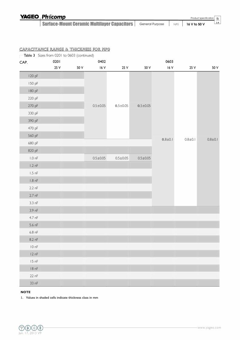
TEST TEST METHOD PROCEDURE REQUIREMENTS
Adhesion 4.7
A force applied for 10 seconds to the line joining the
terminations and in a plane parallel to the substrate
Force
size ≥ 0603: 5N
size = 0402: 2.5N
size = 0201: 1N
Bond strengt
h of plating
on end face
4.8
Mounting in accordance with IEC 60384-22 paragraph 4.3
No visible damage
Conditions: bending 1 mm at a rate of 1 mm/s, radius jig
340 mm
<General purpose series>
∆C/C
Class 1:
NP0: within ±1% or 0.5 pF
whichever is greater
Resistance to
soldering heat IEC 60384-
21/22
4.9
Precondition: 150 +0/–10 °C for 1 hour, then keep for 24
± 1 hours at room temperature
Preheating: for size ≤ 1206: 120 °C to 150 °C for 1 minute
Preheating: for size >1206: 100 °C to 120 °C for 1 minute
and 170 °C to 200 °C for 1 minute
Solder bath temperature: 260 ±5 °C
Dipping time: 10 ± 0.5 seconds
Recovery time: 24 ± 2 hours
Dissolution of the end face plating shall
not exceed 25% of the length of the
edge concerned
<General purpose series>
∆C/C
Class 1:
NP0: within ± 0.5% or 0.5 pF
whichever is greater
D.F. within initial specified value
Rins within initial specified value
Solderability 4.10 Preheated the temperature of 80 °C to 140 °C
and maintained for 30 seconds to 60 seconds.
1. Temperature: 235± 5°C / Dipping time: 2 ±0.5 s
2. Temperature: 245± 5°C / Dipping time: 3 ±0.5 s
(lead free)Depth of immersion: 10mm
The solder should cover over 95% of
the critical area of each termination
Rapid change
of
temperature
4.11 Preconditioning;
150 +0/–10 °C for 1 hour, then keep for
24 ±1 hours at room temperature
5 cycles with following detail:
30 minutes at lower category temperature
30 minutes at upper category temperature
Recovery time 24 ± 2 hours
No visual damage
<General purpose series>
∆C/C
Class 1:
NP0: within ±1% or 1 pF
whichever is greater
D.F. meet initial specified value
Rins meet initial specified value

www.yageo.com
Jun. 17, 2013 V9
Surface-Mount Ceramic Multilayer Capacitors
13
14
Product specification
General Purpose
16 V to 50 V
NP0
TEST TEST METHOD PROCEDURE REQUIREMENTS
Damp heat
with Ur load IEC 60384-
21/22
4.13 1. Preconditioning, class 2 only:
150 +0/-10 °C /1 hour, then keep for
24 ±1 hour at room temp
2. Initial measure:
Spec: refer to initial spec C, D, IR
3. Damp heat test:
500 ± 12 hours at 40 ± 2 °C;
90 to 95% R.H. 1.0 Ur applied
4. Recovery:
Class 1: 6 to 24 hours
5. Final measure: C, D, IR
P.S. If the capacitance value is less than the minimum value
permitted, then after the other measurements have been
made the capacitor shall be preconditioned according to
“IEC 60384 4.1” and then the requirement shall be met.
No visual damage after recovery
<General purpose series>
∆C/C
Class 1:
NP0: within ±2% or 1 pF
whichever is greater
D.F.
Class 1:
NP0: ≤ 2 x specified value
Rins
Class 1:
NP0: ≥ 2,500 MΩ or Rins x Cr ≥ 25s
whichever is less
Endurance 4.14 1. Preconditioning, class 2 only:
150 +0/-10 °C /1 hour, then keep for
24 ±1 hour at room temp
2. Initial measure:
Spec: refer to initial spec C, D, IR
3. Endurance test:
Temperature: NP0: 125 °C
Specified stress voltage applied for 1,000 hours:
Applied 2.0 x Ur for general product.
4. Recovery time: 24 ± 2 hours
5. Final measure: C, D, IR
P.S. If the capacitance value is less than the minimum value
permitted, then after the other measurements have been
made the capacitor shall be preconditioned according to
“IEC 60384 4.1” and then the requirement shall be met.
No visual damage
<General purpose series>
∆C/C
Class1:
NP0: within ±2% or 1 pF
whichever is greater
D.F.
Class1:
NP0: ≤ 2 x specified value
Rins
Class1:
NP0: ≥ 4,000 MΩ or Rins x Cr ≥ 40s
whichever is less
Voltage proof IEC 60384-1 4.6 Specified stress voltage applied for 1 minute
Ur ≤ 100 V: series applied 2.5 Ur
100 V < Ur ≤ 200 V series applied (1.5 Ur + 100)
200 V < Ur ≤ 500 V series applied (1.3 Ur + 100)
Ur > 500 V: 1.3 Ur
I: 7.5 mA
No breakdown or flashover

www.yageo.com
Jun. 17, 2013 V9
Surface-Mount Ceramic Multilayer Capacitors
14
14
Product specification
General Purpose
16 V to 50 V
NP0
REVISION HISTORY
REVISION DATE CHANGE NOTIFICATION DESCRIPTION
Version 9 Jun. 17, 2013 - Product range updated
Version 8 Aug 05, 2011 - Dimension updated
Version 7 Jun 14, 2011 - - Size1210 T=1.0mm SPQ added
- Dimension updated
Version 6 Jan 06, 2011 - - Dimension updated
Version 5 Dec 29, 2010 - - Dimension updated
Version 4 Nov 23, 2010 - - Dimension updated
Version 3 Apr 20, 2010 - - The statement of "Halogen Free" on the cover added
- Dimension updated
Version 2 Oct 26, 2009 - - Typo updated
Version 1 Jun 02, 2009 - - 12NC code updated
Version 0 Apr 15, 2009 - - New datasheet for general purpose NP0 series with RoHS compliant
- Replace the "16V to 50V" part of pdf files: NP0_16V_7, NP0_16V-to-
100V_6, NP0_25V_7, NP0_50-to-500V_11
- Combine 0201 from pdf files: UP-NP0X5RX7RY5V_0201_6.3-to-50V_2
and UY-NPOX5RX7RY5V_0201_6.3-to-50V_2
- Define global part number
- Description of "Halogen Free compliant" added
- Test method and procedure updated

Mouser Electronics
Authorized Distributor
Click to View Pricing, Inventory, Delivery & Lifecycle Information: Yageo:
CC0402CRNPO9BN1R8 CC0603KRX7R6BB474 CC0402BRNPO9BN1R0 CC0402BRNPO9BN2R7
CC0402BRNPO9BN2R2 CC0402BRNPO9BN1R8 CC0402BRNPO9BN1R2 CC0402BRNPO9BNR68
CC0402BRNPO9BNR56 CC0402BRNPO9BNR47 CC0402BRNPO9BN1R5 CC0402BRNPO9BN4R7
CC0402BRNPO9BN6R8 CC0402KRX7R9BB121 CC0402KRX7R9BB102 CC0402KRX7R8BB682
CC0402KRX7R8BB472 CC0402KRX7R8BB103 CC0402KRX7R6BB333 CC0402KRX7R7BB473
CC0402KRX7R7BB333 CC0402KRX7R7BB223 CC0402KRX7R7BB183 CC0402KRX7R7BB153
CC0402KRX7R7BB123 CC0402KRX7R7BB104 CC0402KRX7R6BB683 CC0402BRNPO9BN3R3
CC0402KRX7R7BB822 CC0402KRX7R9BB561 CC0402ZRY5V7BB683 CC0402ZRY5V7BB473
CC0402ZRY5V7BB333 CC0402ZRY5V7BB223 CC0402ZRY5V7BB104 CC0402ZRY5V7BB103
CC0402ZRY5V6BB474 CC0402ZRY5V6BB224 CC0402ZRY5V5BB474 CC0402MRY5V7BB473
CC0402MRY5V7BB104 CC0402KRX7R9BB681 CC0402KRX7R9BB471 CC0402KRX7R9BB391
CC0402KRX7R9BB222 CC0402KRX7R6BB104 CC0402KRX7R9BB821 CC0402CRNPO9BN5R6
CC0402JRNPO9BN121 CC0402JRNPO9BN120 CC0402JRNPO9BN101 CC0402JRNPO9BN100
CC0402JRNPO7BN391 CC0402GRNPO9BN470 CC0402FRNPO9BN121 CC0402DRNPO9BN8R2
CC0402DRNPO9BN6R8 CC0402DRNPO9BN5R6 CC0402CRNPO9BN6R8 CC0402JRNPO9BN180
CC0402CRNPO9BN4R7 CC0402CRNPO9BN3R9 CC0402CRNPO9BN3R3 CC0402CRNPO9BN2R7
CC0402CRNPO9BN2R2 CC0402CRNPO9BN1R5 CC0402CRNPO9BN1R2 CC0402CRNPO9BN1R0
CC0402CRNPO9BNR82 CC0402CRNPO9BNR47 CC0402CRNPO9BN8R2 CC0402JRX7R9BB471
CC0402JRX7R9BB182 CC0402JRX7R9BB152 CC0402JRX7R9BB102 CC0402JRNPO9BN150
CC0402JRX7R7BB223 CC0402JRNPO9BN151 CC0402JRX7R7BB103 CC0402JRNPO9BN820
CC0402JRNPO9BN680 CC0402JRNPO9BN560 CC0402JRNPO9BN470 CC0402JRNPO9BN390
CC0402JRNPO9BN330 CC0402JRNPO9BN270 CC0402JRNPO9BN221 CC0402JRNPO9BN220
CC0402JRX7R7BB472 CC0603JRNPO9BN221 CC0603JRNPO9BN181 CC0603JRNPO9BN271
CC0603KRX7R9BB121 CC0603JRNPO9BN151 CC0603KRX7R8BB473 CC0603KRX7R8BB123
CC0603KRX7R9BB223 CC0603KRX7R9BB102 CC0603KRX7R9BB103 CC0603JRNPO9BN391