Embed Size (px)
Citation preview
ADH-tech ADH Technology Co. Ltd.
www.adh-tech.com.tw [email protected]
Data Sheet / GP-735
Easy to Use,
Slim,
Ultra High Performance,
GPS
Smart Antenna Module
Version 1.0

ADH-tech Data Sheet – GP-735
ii
The specifications in this document are subject to change without prior notice. ADH Technology Co. Ltd. assumes
no warranties (either expressed or implied) regarding the accuracy and completeness of this document and shall
in no event be liable for any loss of profit or any other commercial damage, including but not limited to special,
incidental, consequential, or other damages. ADH-tech products are not intended for use in medical, life-support
devices, commercial aircraft or any applications involving potential risk of personal injury, death, or severe
property damage in case of failure of the product.
No part of this document may be reproduced or transmitted in any form by any means without the express written
permission of ADH Technology Co. Ltd.

ADH-tech Data Sheet – GP-735
iii
Revision History
Ver. Date Description
1.0 June. 5th, 2014 Initial draft
ADH-tech Data Sheet – GP-735
iv
Contents
1 INTRODUCTION..................................................................................................................................... 1
1.1 OVERVIEW ................................................................................................................................ 1
1.2 MAIN FEATURES........................................................................................................................ 1
1.3 RECEIVER SPECIFICATIONS ........................................................................................................ 1
1.4 PROTOCOLS............................................................................................................................... 2
2 HARDWARE INTERFACE ..................................................................................................................... 3
2.1 MODULE DIMENSION ................................................................................................................ 3
2.2 PIN ASSIGNMENT ...................................................................................................................... 4
3 SOFTWARE INTERFACE ...................................................................................................................... 6
3.1 NMEA OUTPUT MESSAGES ....................................................................................................... 6
3.2 GPGGA - GLOBAL POSITIONING SYSTEM FIX DATA ................................................................... 7
3.3 GPGLL - GEOGRAPHIC POSITION - LATITUDE / LONGITUDE ....................................................... 7
3.4 GPGSA - GNSS DOP AND ACTIVE SATELLITES ......................................................................... 8
3.5 GPGSV - GNSS SATELLITES IN VIEW........................................................................................ 8
3.6 GPRMC - RECOMMENDED MINIMUM SPECIFIC GNSS DATA...................................................... 9
3.7 GPVTG - COURSE OVER GROUND AND GROUND SPEED............................................................. 9
4 EVALUATION INFORMATION ........................................................................................................... 11
4.1 OVERVIEW .............................................................................................................................. 11
4.2 ORDERING INFORMATION ........................................................................................................ 12
4.3 TIPS IN DESIGNING ................................................................................ 錯誤! 尚未定義書籤。
5 ELECTRICAL AND ENVIRONMENTAL DATA .............................................................................. 144
ADH-tech Data Sheet - GP-735
1
1 Introduction
1.1 Overview
ADH-tech GP-735 is a slim, ultra-high performance, easy to use GPS smart antenna module
designed with u-blox’s latest 7th generation single chip.
This feature rich GPS module not only shortens the design efforts but also provides powerful
functions. The compact design allows fast adoption and high yield production.
The power control feature is very convenient to turn on/off power just via GPIO control pin. It’s
especially useful to turn off power as the GPS function is not needed in the host applications.
1.2 Main Features
Not only handheld but also any other GPS applications can share the following major features
of GP-735.
Easy adoption with best performance
Built-in narrow patch antenna for dimension demanding application
Models of I-PEX RF connector option available for using external antenna
Built-in backup power pin for faster position fix
USB/UART-TTL interface support
Minimum RF and EMI efforts
Fully implementation of ultra-high performance u-blox7 single chip architecture
High tracking sensitivity of -162 dBm!
Low power consumption of 37mA for average tracking
Hardware power saving control pin allowing power on/off GPS via GPIO
Windows location sensor support
A-GPS support
1.3 Receiver Specifications
Features Specifications!
GPS receiver type 56 channels, L1 frequency, C/A code
ADH-tech Data Sheet - GP-735
2
Horizontal Position Accuracy < 2.5m (Autonomous)
< 2.0m (WAAS)
(CEP, 50%, 24hr static, -130dBm)
Velocity Accuracy <0.1 m/s (speed)
<0.5° (heading)
(50%@30m/s)
Accuracy of Time pulse Signal 30ns (RMS) or <60 ns (99%)
TTFF (Time to First Fix)
(50%, -130dBm, autonomous)
Hot Start: 1s
Warm Start: 28s
Cold Start: 29s
Sensitivity
(Autonomous)
Tracking: –162dBm
Acquisition: -148dBm
Measurement data output Update rate: 1 Hz (default), up to 10 Hz by enabling command
NMEA output protocol: Ver. 2.3 (compatible to 3.0)
UART baud rate: 9600 bps, (N-8-1)
Datum: WGS-84
Default: GGA, GLL, GSA, GSV, RMC, VTG, TXT
Max. Altitude < 50,000 m
Max. Velocity < 1,852 km/hr
SBAS Support WAAS, EGNOS, MSAS, GAGAN
Dynamics < 4g
Power consumption 37mA, continuous tracking mode
Power supply 3.1 ~ 5.5 V (TTL); 4.75~5.25V (USB)
Dimension 8(W) x 35(L) x 6.55(H) (mm )
Operating temperature -40°C ~ +85°C
Storage temperature -40°C ~ +85°C
! Note. According to IC Spec
1.4 Protocols
The NMEA protocol is supported via serial UART (RX/TX) or USB (DM/DP) I/O port. The
default supported protocol is NMEA protocol.
1. Serial communication channel – UART
i. No parity, 8-data bit, 1-stop bit (N-8-1)
ii. 4800, 9600, 38400(default), 57600 bps.
2. NMEA 0183 Version 2.3 ASCII output
i. Default GGA, GSA, GSV, GLL, RMC, VTG and TXT
ADH-tech Data Sheet - GP-735
3
2 Hardware Interface
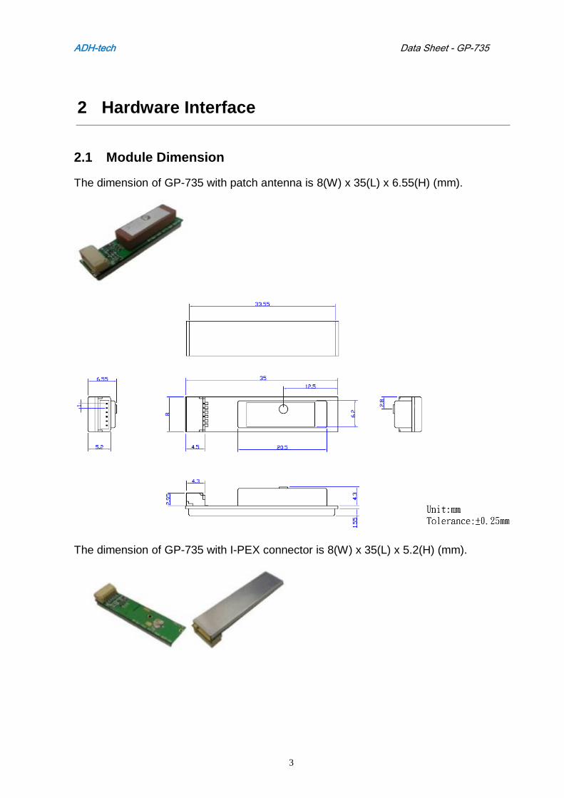
2.1 Module Dimension
The dimension of GP-735 with patch antenna is 8(W) x 35(L) x 6.55(H) (mm).
The dimension of GP-735 with I-PEX connector is 8(W) x 35(L) x 5.2(H) (mm).
ADH-tech Data Sheet - GP-735
4
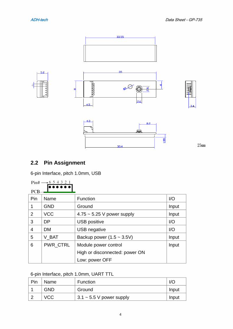
2.2 Pin Assignment
6-pin Interface, pitch 1.0mm, USB
Pin Name Function I/O
1 GND Ground Input
2 VCC 4.75 ~ 5.25 V power supply Input
3 DP USB positive I/O
4 DM USB negative I/O
5 V_BAT Backup power (1.5 ~ 3.5V) Input
6 PWR_CTRL Module power control
High or disconnected: power ON
Low: power OFF
Input
6-pin Interface, pitch 1.0mm, UART TTL
Pin Name Function I/O
1 GND Ground Input
2 VCC 3.1 ~ 5.5 V power supply Input

ADH-tech Data Sheet - GP-735
5
3 TXA Port A serial data output (from GPS) Output
4 RXA Port A serial data input (to GPS) Input
5 V_BAT Backup power (1.5 ~ 3.5V) Input
6 PWR_CTRL Module power control
High or disconnected: power ON
Low: power OFF
Input
Power Saving
GP-735 supports the easy power saving control mechanism via a GPIO pin. To control
the power of GP-735, connect the PWR_CTRL pin to a GPIO of micro-processor. To
cut off the power of GP-735 (VCC is always connected to power source), just pull the
PWR_CTRL pin low (in this case, GP-735 only keeps power of RTC and RAM).
During normal run, pull it high or leave it floating (in this case, GP-735 is fully
powered).
ADH-tech Data Sheet - GP-735
6
3 Software Interface
3.1 NMEA Output Messages
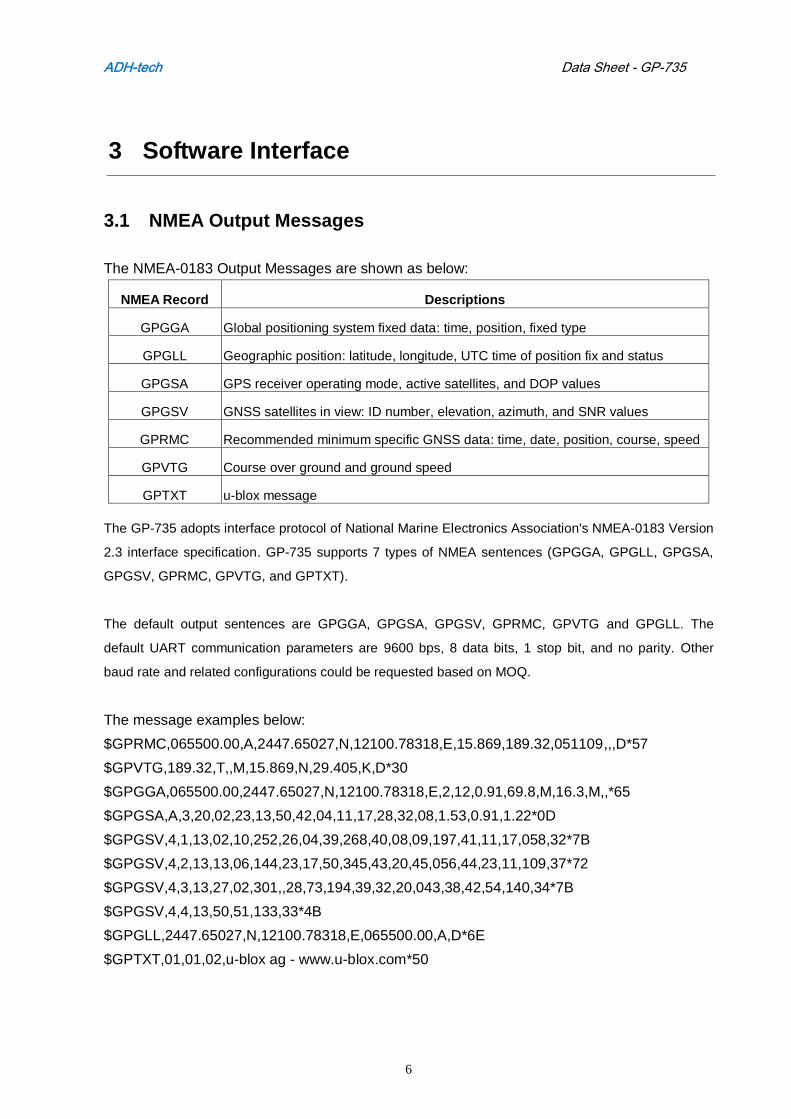
The NMEA-0183 Output Messages are shown as below:
NMEA Record Descriptions
GPGGA Global positioning system fixed data: time, position, fixed type
GPGLL Geographic position: latitude, longitude, UTC time of position fix and status
GPGSA GPS receiver operating mode, active satellites, and DOP values
GPGSV GNSS satellites in view: ID number, elevation, azimuth, and SNR values
GPRMC Recommended minimum specific GNSS data: time, date, position, course, speed
GPVTG Course over ground and ground speed
GPTXT u-blox message
The GP-735 adopts interface protocol of National Marine Electronics Association's NMEA-0183 Version
2.3 interface specification. GP-735 supports 7 types of NMEA sentences (GPGGA, GPGLL, GPGSA,
GPGSV, GPRMC, GPVTG, and GPTXT).
The default output sentences are GPGGA, GPGSA, GPGSV, GPRMC, GPVTG and GPGLL. The
default UART communication parameters are 9600 bps, 8 data bits, 1 stop bit, and no parity. Other
baud rate and related configurations could be requested based on MOQ.
The message examples below:
$GPRMC,065500.00,A,2447.65027,N,12100.78318,E,15.869,189.32,051109,,,D*57
$GPVTG,189.32,T,,M,15.869,N,29.405,K,D*30
$GPGGA,065500.00,2447.65027,N,12100.78318,E,2,12,0.91,69.8,M,16.3,M,,*65
$GPGSA,A,3,20,02,23,13,50,42,04,11,17,28,32,08,1.53,0.91,1.22*0D
$GPGSV,4,1,13,02,10,252,26,04,39,268,40,08,09,197,41,11,17,058,32*7B
$GPGSV,4,2,13,13,06,144,23,17,50,345,43,20,45,056,44,23,11,109,37*72
$GPGSV,4,3,13,27,02,301,,28,73,194,39,32,20,043,38,42,54,140,34*7B
$GPGSV,4,4,13,50,51,133,33*4B
$GPGLL,2447.65027,N,12100.78318,E,065500.00,A,D*6E
$GPTXT,01,01,02,u-blox ag - www.u-blox.com*50
ADH-tech Data Sheet - GP-735
7
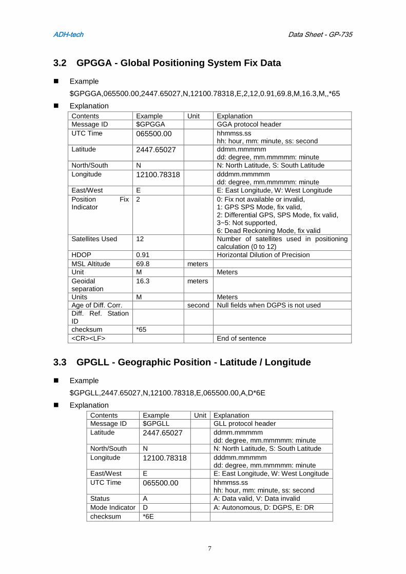
3.2 GPGGA - Global Positioning System Fix Data
Example
$GPGGA,065500.00,2447.65027,N,12100.78318,E,2,12,0.91,69.8,M,16.3,M,,*65
Explanation
Contents Example Unit Explanation Message ID $GPGGA GGA protocol header
UTC Time 065500.00 hhmmss.ss hh: hour, mm: minute, ss: second
Latitude 2447.65027 ddmm.mmmmm dd: degree, mm.mmmmm: minute
North/South N N: North Latitude, S: South Latitude
Longitude 12100.78318 dddmm.mmmmm dd: degree, mm.mmmmm: minute
East/West E E: East Longitude, W: West Longitude
Position Fix Indicator
2 0: Fix not available or invalid, 1: GPS SPS Mode, fix valid, 2: Differential GPS, SPS Mode, fix valid, 3~5: Not supported, 6: Dead Reckoning Mode, fix valid
Satellites Used 12 Number of satellites used in positioning calculation (0 to 12)
HDOP 0.91 Horizontal Dilution of Precision
MSL Altitude 69.8 meters
Unit M Meters
Geoidal separation
16.3 meters
Units M Meters
Age of Diff. Corr. second Null fields when DGPS is not used
Diff. Ref. Station ID
checksum *65
<CR><LF> End of sentence
3.3 GPGLL - Geographic Position - Latitude / Longitude
Example
$GPGLL,2447.65027,N,12100.78318,E,065500.00,A,D*6E
Explanation
Contents Example Unit Explanation Message ID $GPGLL GLL protocol header
Latitude 2447.65027 ddmm.mmmmm dd: degree, mm.mmmmm: minute
North/South N N: North Latitude, S: South Latitude
Longitude 12100.78318 dddmm.mmmmm dd: degree, mm.mmmmm: minute
East/West E E: East Longitude, W: West Longitude
UTC Time 065500.00 hhmmss.ss hh: hour, mm: minute, ss: second
Status A A: Data valid, V: Data invalid
Mode Indicator D A: Autonomous, D: DGPS, E: DR
checksum *6E
ADH-tech Data Sheet - GP-735
8
<CR><LF> End of sentence
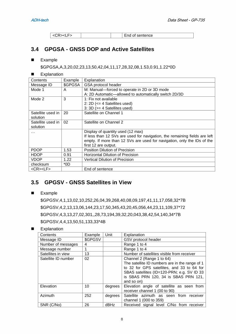
3.4 GPGSA - GNSS DOP and Active Satellites
Example
$GPGSA,A,3,20,02,23,13,50,42,04,11,17,28,32,08,1.53,0.91,1.22*0D
Explanation
Contents Example Explanation
Message ID $GPGSA GSA protocol header
Mode 1 A M: Manual—forced to operate in 2D or 3D mode A: 2D Automatic—allowed to automatically switch 2D/3D
Mode 2 3 1: Fix not available 2: 2D (<= 4 Satellites used) 3: 3D (>= 4 Satellites used)
Satellite used in solution
20 Satellite on Channel 1
Satellite used in solution
02 Satellite on Channel 2
… Display of quantity used (12 max) If less than 12 SVs are used for navigation, the remaining fields are left empty. If more than 12 SVs are used for navigation, only the IDs of the first 12 are output.
PDOP 1.53 Position Dilution of Precision
HDOP 0.91 Horizontal Dilution of Precision
VDOP 1.22 Vertical Dilution of Precision
checksum *0D
<CR><LF> End of sentence
3.5 GPGSV - GNSS Satellites in View
Example
$GPGSV,4,1,13,02,10,252,26,04,39,268,40,08,09,197,41,11,17,058,32*7B
$GPGSV,4,2,13,13,06,144,23,17,50,345,43,20,45,056,44,23,11,109,37*72
$GPGSV,4,3,13,27,02,301,,28,73,194,39,32,20,043,38,42,54,140,34*7B
$GPGSV,4,4,13,50,51,133,33*4B
Explanation
Contents Example Unit Explanation
Message ID $GPGSV GSV protocol header
Number of messages 4 Range 1 to 4
Message number 1 Range 1 to 4
Satellites in view 13 Number of satellites visible from receiver
Satellite ID number 02 Channel 2 (Range 1 to 64) The satellite ID numbers are in the range of 1 to 32 for GPS satellites, and 33 to 64 for SBAS satellites (ID=120-PRN; e.g. SV ID 33 is SBAS PRN 120, 34 is SBAS PRN 121, and so on)
Elevation 10 degrees Elevation angle of satellite as seen from receiver channel 1 (00 to 90)
Azimuth 252 degrees Satellite azimuth as seen from receiver channel 1 (000 to 359)
SNR (C/No) 26 dBHz Received signal level C/No from receiver
ADH-tech Data Sheet - GP-735
9
channel 1 (00 to 99, null when not tracking)
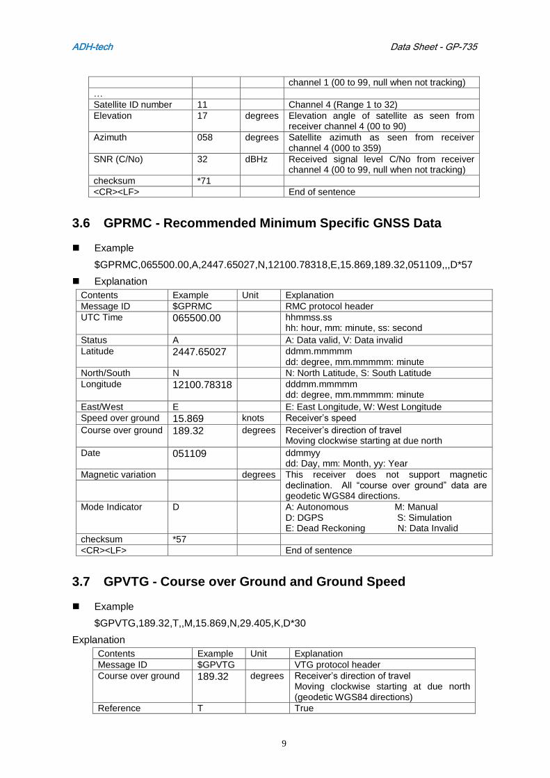
…
Satellite ID number 11 Channel 4 (Range 1 to 32)
Elevation 17 degrees Elevation angle of satellite as seen from receiver channel 4 (00 to 90)
Azimuth 058 degrees Satellite azimuth as seen from receiver channel 4 (000 to 359)
SNR (C/No) 32 dBHz Received signal level C/No from receiver channel 4 (00 to 99, null when not tracking)
checksum *71
<CR><LF> End of sentence
3.6 GPRMC - Recommended Minimum Specific GNSS Data
Example
$GPRMC,065500.00,A,2447.65027,N,12100.78318,E,15.869,189.32,051109,,,D*57
Explanation
Contents Example Unit Explanation
Message ID $GPRMC RMC protocol header
UTC Time
065500.00
hhmmss.ss hh: hour, mm: minute, ss: second
Status A A: Data valid, V: Data invalid
Latitude 2447.65027 ddmm.mmmmm dd: degree, mm.mmmmm: minute
North/South N N: North Latitude, S: South Latitude
Longitude 12100.78318
dddmm.mmmmm dd: degree, mm.mmmmm: minute
East/West E E: East Longitude, W: West Longitude
Speed over ground 15.869 knots Receiver’s speed
Course over ground 189.32
degrees Receiver’s direction of travel Moving clockwise starting at due north
Date 051109 ddmmyy dd: Day, mm: Month, yy: Year
Magnetic variation degrees This receiver does not support magnetic declination. All “course over ground” data are geodetic WGS84 directions.
Mode Indicator D A: Autonomous M: Manual D: DGPS S: Simulation E: Dead Reckoning N: Data Invalid
checksum *57
<CR><LF> End of sentence
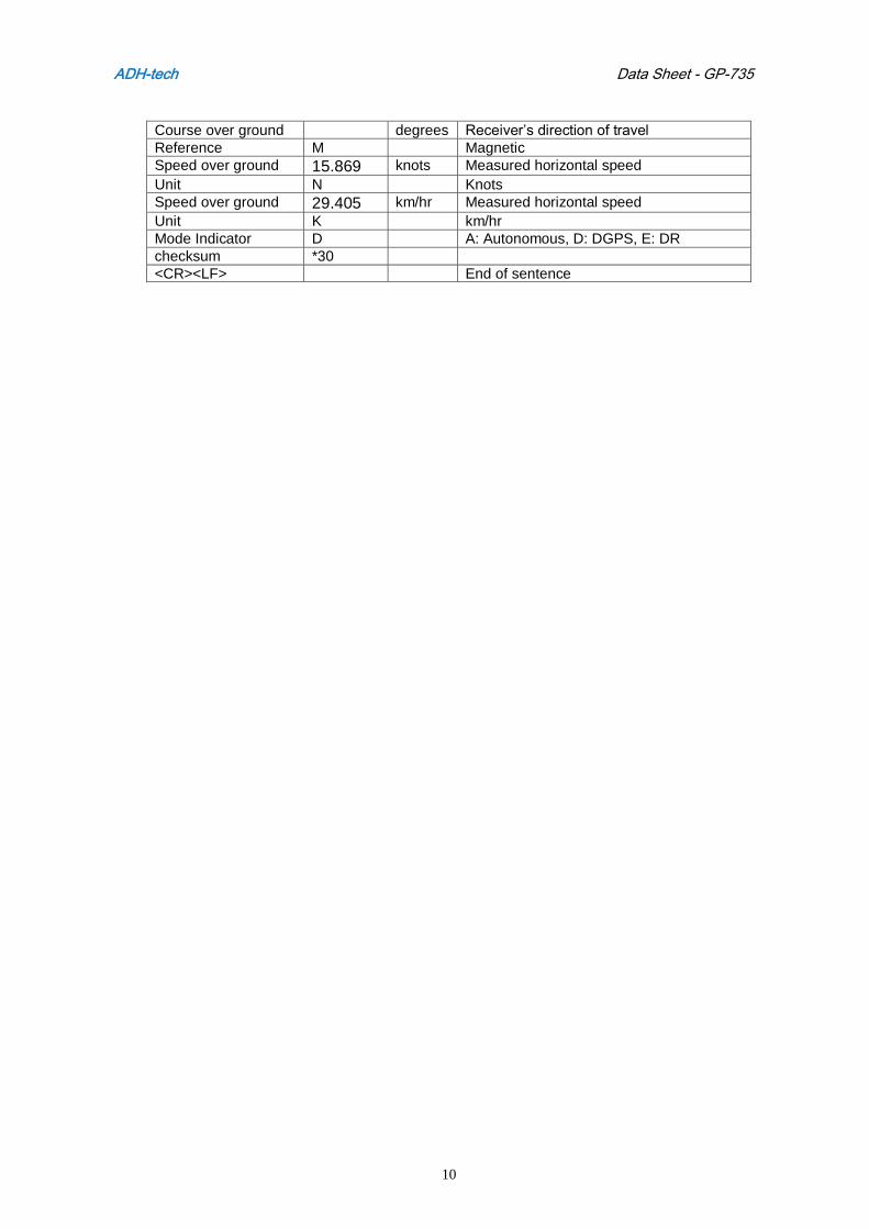
3.7 GPVTG - Course over Ground and Ground Speed
Example
$GPVTG,189.32,T,,M,15.869,N,29.405,K,D*30
Explanation
Contents Example Unit Explanation
Message ID $GPVTG VTG protocol header
Course over ground 189.32 degrees Receiver’s direction of travel Moving clockwise starting at due north (geodetic WGS84 directions)
Reference T True
ADH-tech Data Sheet - GP-735
10
Course over ground degrees Receiver’s direction of travel
Reference M Magnetic
Speed over ground 15.869 knots Measured horizontal speed
Unit N Knots
Speed over ground 29.405 km/hr Measured horizontal speed
Unit K km/hr
Mode Indicator D A: Autonomous, D: DGPS, E: DR
checksum *30
<CR><LF> End of sentence
ADH-tech Data Sheet - GP-735
11
4 Evaluation Information
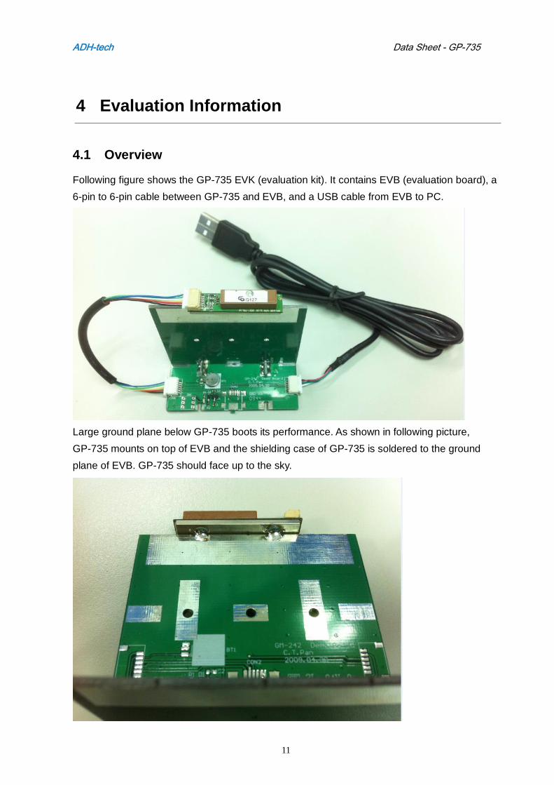
4.1 Overview
Following figure shows the GP-735 EVK (evaluation kit). It contains EVB (evaluation board), a
6-pin to 6-pin cable between GP-735 and EVB, and a USB cable from EVB to PC.
Large ground plane below GP-735 boots its performance. As shown in following picture,
GP-735 mounts on top of EVB and the shielding case of GP-735 is soldered to the ground
plane of EVB. GP-735 should face up to the sky.
ADH-tech Data Sheet - GP-735
12
It’s easy to connect the 6-pin I/O connector and USB cable for checking the performance or
doing power saving control.
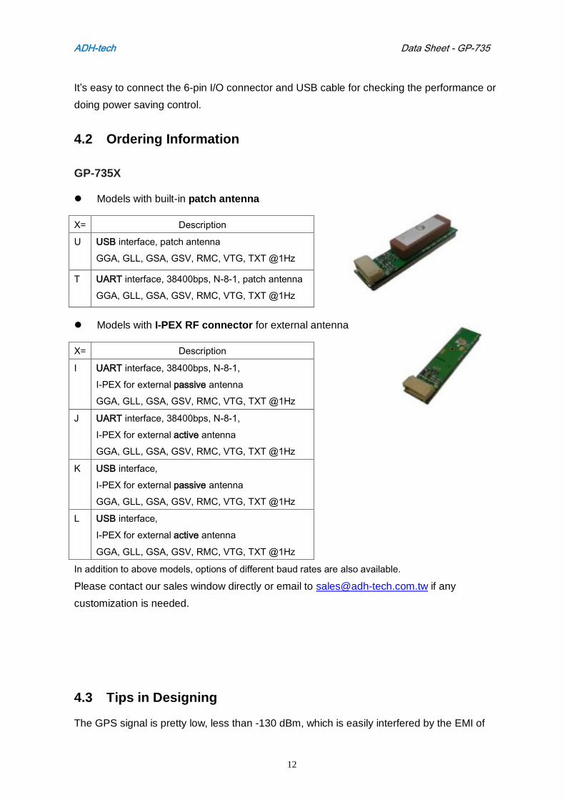
4.2 Ordering Information
GP-735X
Models with built-in patch antenna
X= Description
U USB interface, patch antenna
GGA, GLL, GSA, GSV, RMC, VTG, TXT @1Hz
T UART interface, 38400bps, N-8-1, patch antenna
GGA, GLL, GSA, GSV, RMC, VTG, TXT @1Hz
Models with I-PEX RF connector for external antenna
X= Description
I UART interface, 38400bps, N-8-1,
I-PEX for external passive antenna
GGA, GLL, GSA, GSV, RMC, VTG, TXT @1Hz
J UART interface, 38400bps, N-8-1,
I-PEX for external active antenna
GGA, GLL, GSA, GSV, RMC, VTG, TXT @1Hz
K USB interface,
I-PEX for external passive antenna
GGA, GLL, GSA, GSV, RMC, VTG, TXT @1Hz
L USB interface,
I-PEX for external active antenna
GGA, GLL, GSA, GSV, RMC, VTG, TXT @1Hz
In addition to above models, options of different baud rates are also available.
Please contact our sales window directly or email to [email protected] if any
customization is needed.
4.3 Tips in Designing
The GPS signal is pretty low, less than -130 dBm, which is easily interfered by the EMI of
ADH-tech Data Sheet - GP-735
13
application circuit, and its central frequency, 1.575 GHz might be shifted due to the housing
material of host.
Interference checking
1. Check the signal reception status of GPS module standalone with a GPS viewer tool.
2. Compare it when it is placed at the planned location on the application board.
3. Please find better location or adjust the application to reduce the interference if it
affects the GPS receiving sensitivity.
Antenna working frequency checking
1. Compare the GPS sensitivity with and without host’s housing.
2. If the GPS signal is degraded significantly, the GPS antenna needs to fine tune to
match the housing material to achieve the optimum central frequency and field pattern.
3. Please note that there is MOQ request for antenna customization.
ADH-tech Data Sheet - GP-735
14
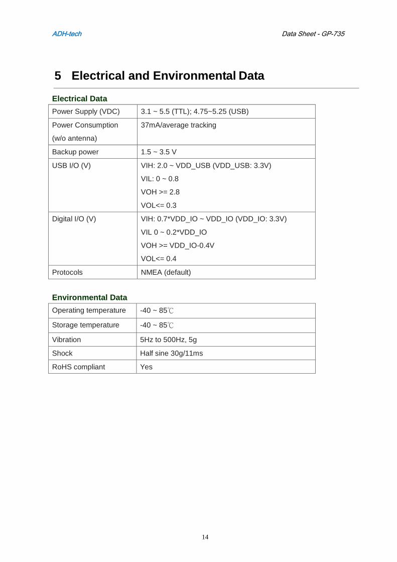
5 Electrical and Environmental Data
Electrical Data
Power Supply (VDC) 3.1 ~ 5.5 (TTL); 4.75~5.25 (USB)
Power Consumption
(w/o antenna)
37mA/average tracking
Backup power 1.5 ~ 3.5 V
USB I/O (V) VIH: 2.0 ~ VDD_USB (VDD_USB: 3.3V)
VIL: 0 ~ 0.8
VOH >= 2.8
VOL<= 0.3
Digital I/O (V) VIH: 0.7*VDD_IO ~ VDD_IO (VDD_IO: 3.3V)
VIL 0 ~ 0.2*VDD_IO
VOH >= VDD_IO-0.4V
VOL<= 0.4
Protocols NMEA (default)
Environmental Data
Operating temperature -40 ~ 85℃
Storage temperature -40 ~ 85℃
Vibration 5Hz to 500Hz, 5g
Shock Half sine 30g/11ms
RoHS compliant Yes