Embed Size (px)
Citation preview
ABB 2600T SeriesEngineered solutionsfor all applications
Models S364 Remote SealsData Sheet DS/S364-EN Rev. D
Wide range of remote seal types- allow optimum design for each application without compromise of performance
Large selection of options, materials and fill fluids- meet nearly all process requirements
All welded constructions- combine an economically feasible and technically sound solution ensuring total reliability at line pressure down to full vacuum
Special designed remote seals for individual process solutions- add flexibility for most demanding services
2600T Pressure TransmittersModels S364 SS/S364_4
2
Remote Seals OverviewThe S364x seals are used in combination with model 364transmitters, allowing differential, gauge or absolute pressuremeasurements.Connection of the seal(s) to the relevant transmitter can beachieved as follows :- directly mounted with a short capillary connecting the "integral"
seal to the transmitter sensor;- through a capillary system which link the transmitter sensor to
a "remote" seal of any version.Using remote seal the transmitter can be selected with- two seals using same fill fluid, capillary and diaphragm size- one seal having the other side configured with a process flange
for wet/dry leg connection or a blind flange providing vacuum oratmospheric reference
- one seal only with a selectable reference to atmosphere orvacuum respectively for gauge or absolute pressuremeasurements.
The S364x Series Seal System is a protective device used toisolate model 364 transmitters from the process fluid.The seal system provides a flexible diaphragm seal between theprocess fluid and a liquid filled capillary tube connected to thebody of the transmitter. The diaphragm isolates the process fluidwhile the filled capillary tube hydraulically transmits the processpressure to the transmitter sensor. The capillary of remote seal iscorrosion-resistant with robust costruction in stainless steel withspiral armour protection, also PVC jacket; PVC protection isalways recommended except for high temperature application,where stainless steel armour is suggested.The all welded construction assures reliable operation over thewidest range of operating temperature and under vacuumconditions.For certain applications, use of seal is necessary to prevent theprocess fluid from leaving its enclosure, due to reasons such as :• the process fluid has solids in suspension or is highly viscous
and can foul impulse lines.• the process fluid can solidify in impulse lines or the
transmitter.• the process fluid is too hazardous to enter the control area
where the transmitter is located.• the process temperature exceeds the recommended limits
for the transmitter.• the application is interface level or density measurement.
Remote seals offer the required constant and equal specificgravity of the pressure transfer fluid on the high and low sidesof the transmitter.
• the transmitter must be located away from the process foreasier maintenance.
The S364x series is available with process connections for ASMEor EN pipe flanges, wedge flow elements, chemical tees, andthreaded pipe fittings. Extended diaphragm remote seals,suitable for connection to 2in - 3in or 4in flanged tank nozzles orflanged tees, permit the seal diaphragm to be located flush withthe inside of a tank or pipe. Sanitary type seals meet the stringentrequirements of sanitary food, dairy, pharmaceutical and BioTech applications, offering FDA approved fillings and compliancewith 3-A Sanitary Standards.Fill fluids with FDA are defined as food fills and are GenerallyRecognized As Safe (GRAS) by the US Food and DrugAdministration (FDA).
Seal system selection criteriaApplication of an S364x system in direct mount or remote sealconfiguration to model 364 transmitters affects performances oforiginal devices. Effects are evident in:- Accuracy- Temperature effects- Dynamic response
• AccuracyAccuracy is only marginally affected when seal diaphragmstiffness is relevant compared with sensor stiffness. This is theonly characteristic of the S364x system which has role onaccuracy performance. High stiffness of diaphragm associatedwith low URL might produce increased errors of linearity,hysteresis, and long term stability; when diaphragm stiffness isaccuracy related also temperature effects are significantlyaffected. Some basic considerations on diaphragm stiffness helpunderstanding effects introduced by S364x system associatedwith transmitters. This is physically defined by the ratio betweenthe pressure variation applied to the diaphragm and thecorresponding volume variation. The stiffness is not linear alongthe whole diaphragm volumetric displacement, but the S364xdesign is such to maintain the system linear within the serviceconditions of the transmitter such as:- Operating pressure range- Operating static pressure (for differential transmitters)- Ambient & process temperature limitsDiaphragm stiffness is a function of material & thickness (elasticcoefficient), diameter (type), convolution shape and geometry(design defined)
• Temperature effectsS364x system has effect on temperature performance of thecomplete transmitter. This effect is mostly on zero of theinstrument and is produced by the expansion of the fill fluid intothe closed volume formed by the transmitter flange cavity thecapillary volume and the remote seal volume. This volume filledwith a fluid with specific expansion coefficient; change in tempe-rature of the measuring device produce a volume variation whichis absorbed by the remote diaphragm, whose stiffness producesa change in the fluid pressure: this is the zero error. In realapplication the transmitter/seal system is not the same and stabletemperature. Therefore the errors referred in this document foreach type of diaphragm and different fluids should be taken as areference for qualitatively evaluation and not a true behaviour innormal application conditions. Should again be recognized thatthe stiffness of diaphragm and in this case, the thermal coefficientof fluid are the parameter to take into account.
• Time responseApplication of S364x seal to transmitters increases the originaltime response. The amount of the increase depends from thenumber of elements and condition of the instrument as follows :- transmitter sensor range- physical configuration (i.e. a remote seal on other side)- type of measure/number of seal (one or two)- fill fluid viscosity of the S364x system applied- ambient temperature (affects the transmitter and the capillary)
and process temperature on the seal diaphragm- capillary length
2600T Pressure TransmittersModels S364 SS/S364_4
3
The delay introduced by the seal may be considered as an addedconstant time to the one of the associated transmitterFor obtaining the best application solution :• choose sensor code with URL closest to application SPAN• select largest diameter diaphragm seal related to URL.• keep the capillary length as short as possible• select the fill fluid that suits the most extreme process
conditions expected (highest temperature and lowestpressure) and it is compatible with the process fluid.
• In vacuum application, choose always the all welded versionand mount the transmitter primary 30 cm/12 inches or morebelow the bottom seal connection.
• In a two-seal system use the same diaphragm size, capillarylength and fill fluid on each side of the transmitter.
Ordering InformationThe transmitter and each seal system are each identified by aproduct code number. These code numbers are stamped on thetransmitter nameplate and each character identifies specificproduct features. Refer to ordering information for a detailedexplanation of the product code numbers.A typical example of the product code stamping is as follows :
Transmitter Product Code 364DRGSH203H–ENL1Seal System Product Code S364WHBCDFSBES1NNN
Industrial application in chemical, sanitary, food and any otherprocess industries may require seal configurations and/orprocess connection different from those reported in thisdocument. Each “special” should be evaluated by ABB to checkthe correctness and its level of functionality. Ask for the “S364xseries seal form” to define precisely the measuring problem andapplication requirements.
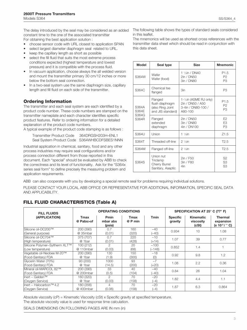
The following table shows the types of standard seals consideredin this leaflet.The mnemonics will be used as shortest cross references with thetransmitter data sheet which should be read in conjunction withthis data sheet.
ABB can also cooperate with you by developing a special remote seal for problems requiring individual solutions.
PLEASE CONTACT YOUR LOCAL ABB OFFICE OR REPRESENTATIVE FOR ADDITIONAL INFORMATION, SPECIFIC SEAL DATAAND APPLICABILITY.
Absolute viscosity (cP) = Kinematic Viscosity (cSt) x Specific gravity at specified temperature.The absolute viscosity value is used for response time calculation.
SEALS DIMENSIONS ON FOLLOWING PAGES ARE IN mm (in)
FILL FLUID CHARACTERISTICS (Table A)
ledoM epytlaeS eziS cinomenM
W463SrefaW
)doof(refaW
1 1/2 04ND/ni05ND/ni208ND/ni3
5.1P2P3P
C463SeetlacimehC
degnalfni3 3P
A463SE463SG463SR463S
degnalFmgarhpaidhsulftnioJgniRosla(
)dradnatsSIJdna
-1 1/2 )ylnoJREMSA(ni05A/05ND/ni2
/001-08ND/ni4-3001-08A
5.1P2P3P
degnalFdednetxemgarhpaid
05ND/ni208ND/ni3
001ND/ni4
2E3E3P
U463S noinU 1 1/2 ni 5.1Z
T463S enil-ffodedaerhT 2 1/2 ni 5.2T
M463S enil-ffodegnalF 2 1/2 ni 5.2T
S463S
tunnoinUpmalcirT
lerruByrrehCcitpesA,yratinaS
05F/ni208F/ni3
ni4
2S3S3S
SDIULFLLIF)NOITACILPPA(
SNOITIDNOCGNITAREPO )F°77(C°52TANOITACIFICEPS
xamTfo>sbaP@
nimPsbarabm
)aisp(
xamTnimP@
nimT cificepSytivarg
citameniKytisocsiv
)tSc(
lamrehTnoisnapxe
01x( 3- )C°/™002CD-lioenociliS
)esopruplareneG()093(002rabm53@
7.0)10.0(
061)023(
04–)04–(
439.0 01 80.1
™407CD-lioenociliS)erutarepmethgiH(
)707(573rab1@
7.0)10.0(
022)824(
01–)41+(
70.1 93 77.0
™TLXmrehtlyS–remyloPenociliS)erutarepmetwoL(
)212(001rabm011@
2)30.0(
02)86(
001–)841–(
258.0 4.1 1
™02-MeeboeN-lioelbategeVADF)yratinaS-dooF(
)093(002rab1@
031)9.1(
051)003(
81–)0(
29.0 8.9 2.1
)%07(retaWnirecylGADF)yratinaS-dooF(
)002(39rab1@
0001)5.41(
39)002(
7–)02+(
80.1 2.2 63.0
™28LOCRAM-liolareniMADF)yratinaS-dooF(
)093(002rabm002@
33)5.0(
04)401(
04–)04–(
48.0 62 40.1
™nedlaG–trenI)ecivreSnegyxO(
)023(061rab1@
2)30.0(
07)851(
02–)4–(
28.1 4.4 1.1
2.4™nobracolaH–trenI)ecivreSnegyxO(
)653(081rabm004@
4)60.0(
07)851(
02–)4–(
78.1 3.6 468.0

2600T Pressure TransmittersModels S364 SS/S364_4
4
S364W Model Wafer Remote SealThe wafer remote seal is designed to be clamped between two ASME or EN raised face flanges. The diaphragm side of the seal facesthe process flange and a blind back-up flange is used on the other side of the seal.The wafer variant is also available as food design for 11/2in and 3in sizes.
134
(5.3
)
B
A /
A1
C
D
Flushing ring(OPTION)
25 (0.98) for 1/4 NPT
33 (1.30) for 1/2 NPTflushing thread(s)
Capillary toinstrument
Capillary toinstrument
Gasket seat finish
23 (0.9);25 (0.98)
for 1-1/2in food
eziS
)ni(mmSNOISNEMID
)aid(A.hpaid
1AgnihsulF
.aid.tnignir
)aid(B C D
1 1/2 ni )79.1(05 )50.2(25 )78.2(37 )20.3(8.67
6.1)60.0(
ni2 )63.2(06 )44.2(26 )26.3(29 )77.3(8.59
ni3 )5.3(98 )26.3(29 )5(7218.031)51.5(
04ND )79.1(05 )50.2(25 )64.3(88 )26.3(29
3)21.0(
05ND )63.2(06 )44.2(26201
)20.4()71.4(601
08ND )5.3(98 )26.3(29831
)34.5()95.5(241
1 1/2 ni)doof(
)79.1(05 )50.2(25 )78.2(37 )20.3(8.67 .A.N
ni3)doof(
)5.3(98 )26.3(29 )5(7218.031)51.5(
7.3)51.0(

2600T Pressure TransmittersModels S364 SS/S364_4
5
Maximum Working Pressure
WAFER SEAL ELEMENT : 16 MPa, 160 bar, 2320 psi but notgreater than the backup flange rating (not supplied).
Vacuum Service
Full vacuum subject to fill fluid limits. Refer to table A.
Minimum pressure with tantalum diaphragm is 1kPa abs, 10mbar abs,0.15psia.
Process Temperature Limits
Same as fill fluid limits. Refer to table A.
260°C (500°F) for Tantalum diaphragm.
204°C (400°F) for use with Teflon anti-stick coating.
320°C (608°F) for AISI gold plated diaphragm.
Limits for gaskets of flushing rings
Gasket seat finish
Smooth (ASME or EN): 0.8µm (Ra)
Serrated (ASME): 3.2 to 6.3µm (Ra)
Serrated (EN 1092-1 Type B1; up to PN40): 3.2 to 12.5 µm (Ra)
Serrated (EN 1092-1 Type B2; PN63 - 100): 0.8 to 3.2 µm (Ra)
Temperature effect
The following table shows the temperature effect for 20K (36°F)change, detailed separately for
a) the seal (one element)
b) the capillary per meter
c) the system (transmitter sensor when combined with a seal ofspecific size/type)
referred to silicone oil (DC 200) filling and AISI 316 L ss diaphragmmaterials.
For filling different from silicone oil (DC200) the errors can be multipliedby ratio between the thermal expansion coefficients of the selectedfilling divided by the one of DC200, listed in the fill fluid characteristicstable.
THE ERRORS IN TABLE CAN BE CONSIDERED DIVIDED BY 4 FORTRANSMITTERS USING SAME REMOTE SEAL ON THE TWO SIDES
eziSlaeSrefaW rorrelaeS rorrEyrallipaCm1 rorrE)rosneS(metsyS
1 1/2 04ND/ni Hni5.3,rabm7.8,aPk78.0 2O Hni2.1,rabm3,aPk3.0 2O Hni6.3,rabm9,aPk9.0 2O
05ND/ni2 Hni61.1,rabm9.2,aPk92.0 2O Hni82.0,rabm7.0,aPk70.0 2O Hni8.0,rabm2,aPk2.0 2O
08ND/ni3 Hni63.0,rabm9.0,aPk90.0 2O Hni21.0,rabm3.0,aPk30.0 2O Hni21.0,rabm3.0,aPk30.0 2O
lairetaM erusserP).xam(
erutarepmeT).nim().xam(
timilTxP
kcolraG,rab96,aPM9.6
isp0001C°402
)F°004(C°37–
)F°001–(000052
)ispxF°(
etihparG,rab52,aPM5.2
isp263C°083
)F°617(C°001–
)F°841–(
EFTP,rab06,aPM6
isp078C°052
)F°284(C°001–
)F°841–(

2600T Pressure TransmittersModels S364 SS/S364_4
6
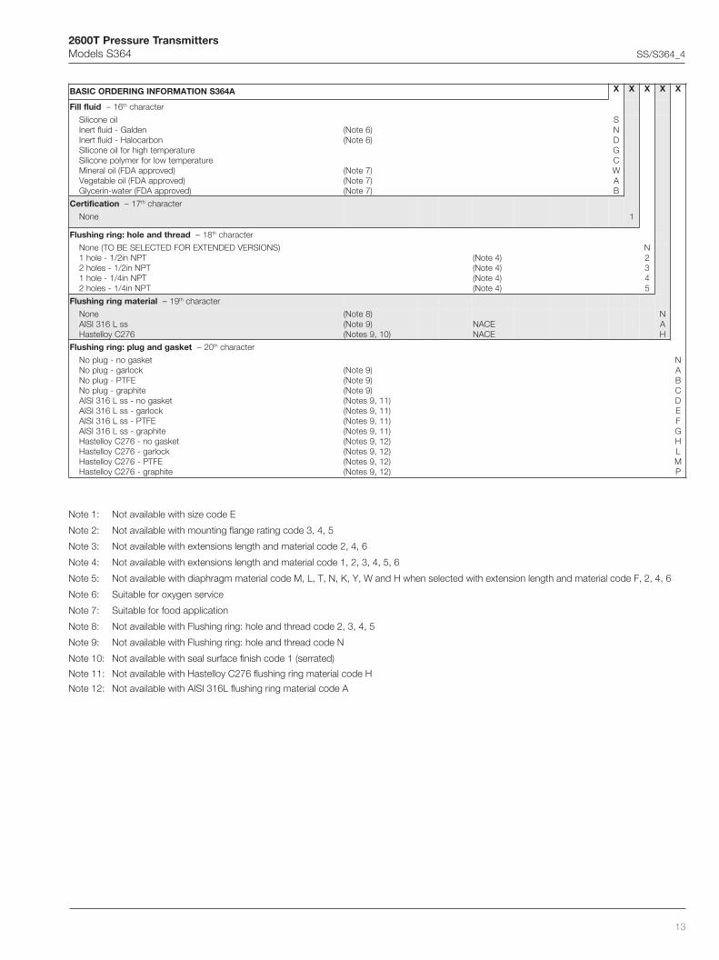
BASIC ORDERING INFORMATION model S364W Wafer Remote SealSelect one character or set of characters from each category and specify complete catalog number.
LEDOMESAB 1– ts 5ot ht sretcarahc S 3 6 4 W X X X X F X X X X X d'tnoC
laeSetomeRrefaW
–noitcennocfoedisrettimsnarT 6 ht retcarahcedishgiHediswoL
HL
metsysgniretneC 7– ht retcarahc)egnalfpukcabEMSArofelbatius(retemaidkcabnotaeS B
eziS – 8 ht retcarahc
1 1/2 EMSAniEMSAni2EMSAni3
1 1/2 ngiseddoofEMSAningiseddoofEMSAni3
04NDNE05NDNE08NDNE
ABC12DEF
hsiniftaeS 9– ht retcarahc
)EMSArofelbatius(hsinifdetarreS)EMSArofelbatius(hsinifhtoomS
04NPotpu;1BepyT1-2901NEothsinifdetarreS001NPot36NP;2BepyT1-2901NEothsinifdetarreS
)NErofelbatius(hsinifhtoomS
)2,1setoN()1etoN(
)3,2setoN()3,2setoN()3,2setoN(
DERST
edocesU 01– ht retcarahc F
lairetammgarhpaiD 11– ht retcarahc
ssL613ISIA™672CyolletsaH
™0002CyolletsaH526lenocnI
mulatnaTdetalpdlogssL613ISIA
gnitaockcits–itnahtiwssL613ISIAgnitaockcits–itnahtiw™672CyolletsaH
gnitaockcits-itnadnanoisorroc-itnahtiwssL613ISIA)tnemtaertnoisarbAitnAhtiwISIA(xelfaiD
)974ASMTSAot05723SSNU(ssxelpudrepuS
)4,2setoN()4,2setoN()4,2setoN()4,2setoN()4,2setoN()4,2setoN()4,2setoN()4,2setoN(
)2etoN()2etoN(
ECANECANECANECAN
ECANECANECANECANECANECAN
SHMLTNKYWFE
noitcetorpyrallipaC 21– ht retcarahc
ruomrassL613ISIArevocevitcetorpCVPhtiwruomrassL613ISIA
)ERUTAREPMETHGIHROFDEDNEMMOCER( AB
)teef(mhtgnelyrallipaC 31– ht retcarahc
)3(1)5(5.1
)7(2)8(5.2)01(3
)21(5.3)31(4
)51(5.4)71(5
)81(5.5)02(6
)22(5.6)32(7
)52(5.7)72(8)03(9
)33(01)04(21)74(41)35(61
ABCDEFGHJKLMNPQRSTUV
diulflliF 41– ht retcarahc
lioenociliSnedlaG-diulftrenI
nobracolaH-diulftrenIerutarepmethgihroflioenocilIS
erutarepmetwolrofremylopenociliS)devorppaADF(liolareniM
)devorppaADF(lioelbategeV)devorppaADF(retaw-nirecylG
)5,2setoN()5,2setoN(
)2etoN()2etoN()6etoN()6etoN()6etoN(
SNDGCWAB
noitacifitreC 51– ht retcarahc
enoN 1

2600T Pressure TransmittersModels S364 SS/S364_4
7
Note 1: Not available with EN size code D, E, F
Note 2: Not available with food design size code 1, 2
Note 3: Not available with ASME size code A, B, C
Note 4: Not available with serrated seat finish code D, R, S
Note 5: Suitable for oxygen service
Note 6: Suitable for food application
Note 7: Not available with flushing ring - hole and thread code 2, 3, 4, 5
Note 8: Not available with flushing ring - hole and thread code N
Note 9: Not available with Hastelloy C276 flushing ring material code H
Note 10: Not available with AISI 316L flushing ring material code A
W463SNOITAMROFNIGNIREDROCISAB X X X
daerhtdnaeloh:gnirgnihsulF 61– ht retcarahc
enoNTPNni2/1-eloh1TPNni2/1-seloh2
TPNni4/1-eloh1TPNni4/1-seloh2
N2345
lairetamgnirgnihsulF 71– ht retcarahc
enoNssL613ISIA
672CyolletsaH
)7etoN()8etoN(
)8,4setoN(ECANECAN
NAH
teksagdnagulp:gnirgnihsulF 81– ht retcarahc
teksagon-gulpoNkcolrag-gulpoN
EFTP-gulpoNetihparg-gulpoN
teksagon-ssL613ISIAkcolrag-ssL613ISIA
EFTP-ssL613ISIAetihparg-ssL613ISIA
teksagon-672CyolletsaHkcolrag-672CyolletsaH
EFTP-672CyolletsaHetihparg-672CyolletsaH
)8etoN()8etoN()8etoN(
)9,8setoN()9,8setoN()9,8setoN()9,8setoN()01,8setoN()01,8setoN()01,8setoN()01,8setoN(
NABCDEFGHLMP
2600T Pressure TransmittersModels S364 SS/S364_4
8
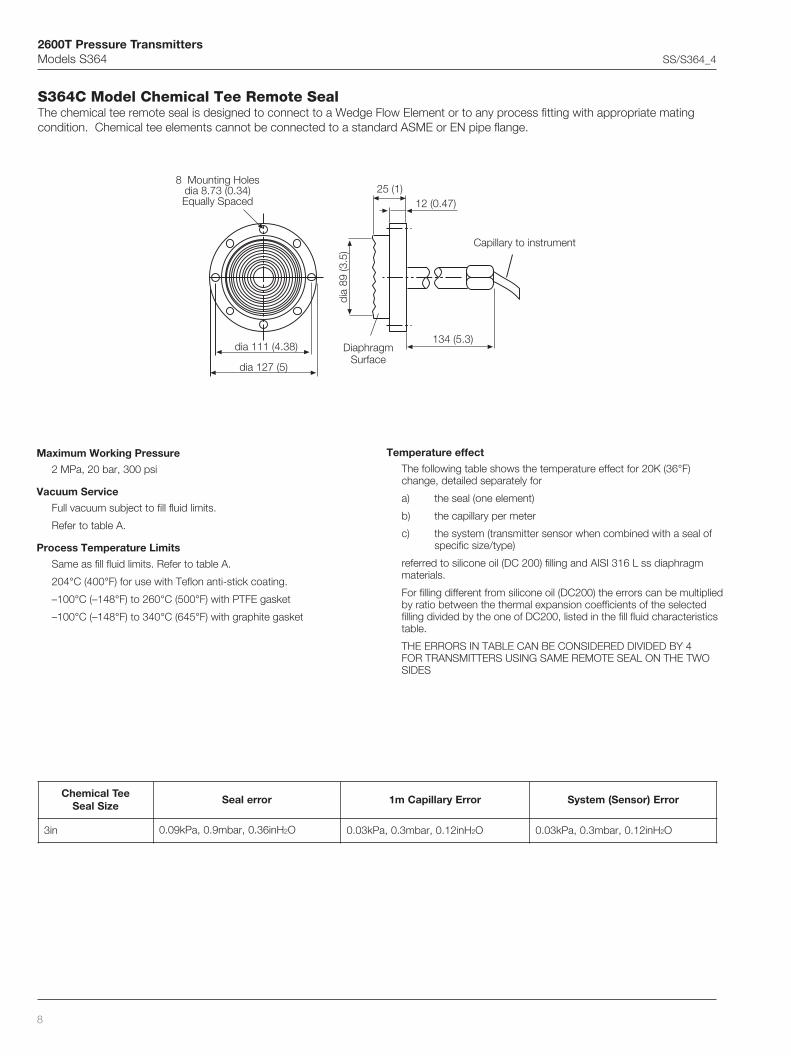
S364C Model Chemical Tee Remote SealThe chemical tee remote seal is designed to connect to a Wedge Flow Element or to any process fitting with appropriate matingcondition. Chemical tee elements cannot be connected to a standard ASME or EN pipe flange.
Maximum Working Pressure
2 MPa, 20 bar, 300 psi
Vacuum Service
Full vacuum subject to fill fluid limits.
Refer to table A.
Process Temperature Limits
Same as fill fluid limits. Refer to table A.
204°C (400°F) for use with Teflon anti-stick coating.
–100°C (–148°F) to 260°C (500°F) with PTFE gasket
–100°C (–148°F) to 340°C (645°F) with graphite gasket
Temperature effect
The following table shows the temperature effect for 20K (36°F)change, detailed separately for
a) the seal (one element)
b) the capillary per meter
c) the system (transmitter sensor when combined with a seal ofspecific size/type)
referred to silicone oil (DC 200) filling and AISI 316 L ss diaphragmmaterials.
For filling different from silicone oil (DC200) the errors can be multipliedby ratio between the thermal expansion coefficients of the selectedfilling divided by the one of DC200, listed in the fill fluid characteristicstable.
THE ERRORS IN TABLE CAN BE CONSIDERED DIVIDED BY 4FOR TRANSMITTERS USING SAME REMOTE SEAL ON THE TWOSIDES
Capillary to instrument
DiaphragmSurface
eeTlacimehCeziSlaeS
rorrelaeS rorrEyrallipaCm1 rorrE)rosneS(metsyS
ni3 Hni63.0,rabm9.0,aPk90.0 2O Hni21.0,rabm3.0,aPk30.0 2O Hni21.0,rabm3.0,aPk30.0 2O
dia 127 (5)
dia
89 (3
.5)
8 Mounting Holesdia 8.73 (0.34)Equally Spaced
134 (5.3)
25 (1)12 (0.47)
dia 111 (4.38)

2600T Pressure TransmittersModels S364 SS/S364_4
9
BASIC ORDERING INFORMATION model S364C Chemical Tee Remote SealSelect one character or set of characters from each category and specify complete catalog number.
Note 1: Suitable for oxygen service
Note 2: Suitable for food application
LEDOMESAB 1– ts 5ot ht sretcarahc S 3 6 4 C X X X P X X X X X
laeSetomeReeTlacimehC
–noitcennocfoedisrettimsnarT 6 ht retcarahcedishgiHediswoL
HL
egnalfgnitnuoM 7– ht retcarahclaeshtiwlargetnI P
eziS 8– ht retcarahc)gnitarrab02;dradnatsyrateirporp(ni3 G
edocesU 9– ht retcarahc P
lairetammgarhpaiD 01– ht retcarahc
ssL613ISIA™672CyolletsaH
gnitaockcits–itnahtiwssL613ISIAgnitaockcits–itnahtiw™672CyolletsaH
)tnemtaertnoisarba-itnahtiwISIA(xelfaiDgnitaockcits-itnadnanoisorroc-itnahtiwssL613ISIA
ECANECANECANECANECANECAN
SHKYFW
noitcetorpyrallipaC 11– ht retcarahc
ruomrassL613ISIArevocevitcetorpCVPhtiwruomrassL613ISIA
)ERUTAREPMETHGIHROFDEDNEMMOCER( AB
)teef(mhtgnelyrallipaC 21– ht retcarahc
)3(1)5(5.1
)7(2)8(5.2
)01(3)21(5.3
)31(4)51(5.4
)71(5)81(5.5
)02(6)22(5.6
)32(7)52(5.7
)72(8)03(9
)33(01
ABCDEFGHJKLMNPQRS
diulflliF 31– ht retcarahc
lioenociliSnedlaG-diulftrenI
nobracolaH-diulftrenIerutarepmethgihroflioenocilIS
erutarepmetwolrofremylopenociliS)devorppaADF(liolareniM
)devorppaADF(lioelbategeV)devorppaADF(retaw-nirecylG
)1etoN()1etoN(
)2etoN()2etoN()2etoN(
SNDGCWAB
teksaG 41– ht retcarahc
enoNrellifaciliShtiwEFTP
etihparG
167

2600T Pressure TransmittersModels S364 SS/S364_4
10
S364A - S364E Models Flanged Extended and Flush Diaphragm Remote SealThe extended and flush diaphragm remote seal is designed to connect to flanged pipe fitting, according to ASME (mod. S364A) orEN (mod. S364E) standards. For liquid level measurement installations the seal connects to an ASME or EN flanged tank nozzle(Schedule 40). The sealing is provided by a selectable smooth or serrated gasket seat surface finish.
Flanged Extended Diaphragm Seal Flanged Flush Diaphragm Seal
Capillary toInstrument
Capillary toInstrument
158 (6.22)
E
C A B
F G
D50, 100 or 150mm(1.97, 3.94 or 5.91)
insertion length is available
gnitaR/eziS gnitaR/eziS gnitaR/eziS gnitaR/eziS gnitaR/eziS
)ni(mmsnoisnemiD )ni(mmsnoisnemiD )ni(mmsnoisnemiD )ni(mmsnoisnemiD )ni(mmsnoisnemiDfo°N fo°N fo°N fo°N fo°Nseloh seloh seloh seloh seloh)aid(A )aid(A )aid(A )aid(A )aid(A
)aid(B )aid(B )aid(B )aid(B )aid(B )aid(C )aid(C )aid(C )aid(C )aid(C )aid(D )aid(D )aid(D )aid(D )aid(D )aid(E )aid(E )aid(E )aid(E )aid(E FFFFF GGGGGdednetxe dednetxe dednetxe dednetxe dednetxemgarhpaid mgarhpaid mgarhpaid mgarhpaid mgarhpaid
hsulf hsulf hsulf hsulf hsulfmgarhpaid mgarhpaid mgarhpaid mgarhpaid mgarhpaid
gnirgnihsulf gnirgnihsulf gnirgnihsulf gnirgnihsulf gnirgnihsulfaidlanretni aidlanretni aidlanretni aidlanretni aidlanretni
051LCEMSAni2003LCEMSAni2006LCEMSAni2009LCEMSAni20051LCEMSAni2
051LCEMSAni3003LCEMSAni3006LCEMSAni3009LCEMSAni30051LCEMSAni3051LCEMSAni4003LCEMSAni4
)9.1(84)9.1(84
ANANAN
)38.2(27)38.2(27
ANANAN
)7.3(49)7.3(49
)63.2(06)63.2(06)63.2(06)63.2(06)63.2(06
)5.3(98)5.3(98)5.3(98)5.3(98)5.3(98)5.3(98)5.3(98
)44.2(26)44.2(26)44.2(26)44.2(26)44.2(26)26.3(29)26.3(29)26.3(29)26.3(29)26.3(29)26.3(29)26.3(29
)26.3(29)26.3(29)26.3(29)26.3(29)26.3(29
)5(721)5(721)5(721)5(721)5(721
)2.6(2.751)2.6(2.751
)57.4(56.021)5(721)5(721)5.6(561)5.6(561)6(4.251
)26.6(51.861)26.6(51.861
)5.7(5.091)8(2.302)5.7(5.091)88.7(2.002
)6(4.251)5.6(1.561)5.6(1.561)5.8(9.512)5.8(9.512)5.7(5.091)52.8(55.902)52.8(55.902
)84.9(142)5.01(7.662
)9(6.822)01(452
)97.0(02)97.0(02)97.0(02)20.1(62)20.1(62)97.0(02)68.0(22)68.0(22)20.1(62
)52.1(57.13)97.0(02)68.0(22
)57.0(50.91)88.0(53.22
)1(4.52)5.1(1.83)5.1(1.83)49.0(78.32)21.1(44.82)52.1(57.13
)05.1(1.83)88.1(8.74
)49.0(42)62.1(23
)73.0(5.9)73.0(5.9)73.0(5.9)73.0(5.9)73.0(5.9)73.0(5.9)73.0(5.9)73.0(5.9)73.0(5.9)73.0(5.9)73.0(5.9)73.0(5.9
488884888888
gnitaR/eziS gnitaR/eziS gnitaR/eziS gnitaR/eziS gnitaR/eziS
)ni(mmsnoisnemiD )ni(mmsnoisnemiD )ni(mmsnoisnemiD )ni(mmsnoisnemiD )ni(mmsnoisnemiDfo°N fo°N fo°N fo°N fo°Nseloh seloh seloh seloh seloh)aid(A )aid(A )aid(A )aid(A )aid(A
)aid(B )aid(B )aid(B )aid(B )aid(B )aid(C )aid(C )aid(C )aid(C )aid(C )aid(D )aid(D )aid(D )aid(D )aid(D )aid(E )aid(E )aid(E )aid(E )aid(E FFFFF GGGGGdednetxe dednetxe dednetxe dednetxe dednetxemgarhpaid mgarhpaid mgarhpaid mgarhpaid mgarhpaid
hsulf hsulf hsulf hsulf hsulfmgarhpaid mgarhpaid mgarhpaid mgarhpaid mgarhpaid
gnirgnihsulf gnirgnihsulf gnirgnihsulf gnirgnihsulf gnirgnihsulfaidlanretni aidlanretni aidlanretni aidlanretni aidlanretni
61NPNE05ND04NPNE05ND36NPNE05ND
001NPNE05ND61NPNE08ND04NPNE08ND36NPNE08ND
001NPNE08ND61NPNE001ND04NPNE001ND
)9.1(84)9.1(84
ANAN
)38.2(27)38.2(27
ANAN
)7.3(49)7.3(49
)63.2(06)63.2(06)63.2(06)63.2(06)5.3(98)5.3(98)5.3(98)5.3(98)5.3(98)5.3(98
)44.2(26)44.2(26)44.2(26)44.2(26)26.3(29)26.3(29)26.3(29)26.3(29)26.3(29)26.3(29
)20.4(201)20.4(201)20.4(201)20.4(201)34.5(831)34.5(831)34.5(831)34.5(831)22.6(851)83.6(261
)29.4(521)29.4(521)13.5(531)17.5(541)3.6(061)3.6(061)7.6(071)80.7(081)80.7(081)84.7(091
)5.6(561)5.6(561)80.7(081)76.7(591)78.7(002)78.7(002)64.8(512)50.9(032)66.8(022)52.9(532
)17.0(81)17.0(81)68.0(22)20.1(62)17.0(81)17.0(81)68.0(22)20.1(62)17.0(81)68.0(22
)97.0(02)97.0(02)20.1(62)1.1(82)97.0(02)49.0(42)1.1(82)62.1(23)97.0(02)49.0(42
)73.0(5.9)73.0(5.9)73.0(5.9)73.0(5.9)73.0(5.9)73.0(5.9)73.0(5.9)73.0(5.9)73.0(5.9)73.0(5.9
4444888888
25 (0.98) for 1/4 NPT
33 (1.30) for 1/2 NPTflushing thread(s)
Flushing ring(OPTION)
158 (6.22)
B
F G
C
E
A D

2600T Pressure TransmittersModels S364 SS/S364_4
11
Maximum Working Pressure
The pressure limit decreases with increasing temperature above120°C for carbon steel or 20°C for AISI 316 stainless steel,according to EN 1092-1 standards.
The pressure limit decreases with increasing temperature above100°F (38°C), according to ASME B16.5 standards.
Vacuum Service
Full vacuum subject to fill fluid limits. Refer to table A.
Minimum pressure with tantalum diaphragm is 1kPa abs,10mbar abs, 0.15psia.
Process Temperature Limits
Same as fill fluid limits. Refer to table A.
260°C (500°F) for Tantalum diaphragm.
204°C (400°F) for use with Teflon anti-stick coating.
320°C (608°F) for AISI gold plated diaphragm.
dednetxEdegnalFmgarhpaiDeziSlaeS
rorrelaeS rorrEyrallipaCm1 rorrE)rosneS(metsyS
05ND/ni2 Hni2.1,rabm3,aPk3.0 2O Hni4.0,rabm1,aPk1.0 2O Hn2.1,rabm3,aPk3.0 2O
08ND/ni3 Hni6.0,rabm5.1,aPk51.0 2O Hni23.0,rabm8.0,aPk80.0 2O Hni82.0,rabm7.0,aPk70.0 2O
001ND/ni4 Hni63.0,rabm9.0,aPk90.0 2O Hni21.0,rabm3.0,aPk30.0 2O Hni21.0,rabm3.0,aPk30.0 2O
hsulFdegnalFmgarhpaiDeziSlaeS
rorrelaeS rorrEyrallipaCm1 rorrE)rosneS(metsyS
05ND/ni2 Hni61.1,rabm9.2,aPk92.0 2O Hni82.0,rabm7.0,aPk70.0 2O Hni8.0,rabm2,aPk2.0 2O
08ND/ni3 Hni63.0,rabm9.0,aPk90.0 2O Hni21.0,rabm3.0,aPk30.0 2O Hni21.0,rabm3.0,aPk30.0 2O
001ND/ni4 Hni63.0,rabm9.0,aPk90.0 2O Hni21.0,rabm3.0,aPk30.0 2O Hni21.0,rabm3.0,aPk30.0 2O
Flanged Extended Diaphragm Remote Seal
Flanged Flush Diaphragm Remote Seal
Gasket seat finish
Smooth (ASME or EN): 0.8µm (Ra)
Serrated (ASME): 3.2 to 6.3µm (Ra)
Serrated (EN 1092-1 Type B1; up to PN40): 3.2 to 12.5 µm (Ra)
Serrated (EN 1092-1 Type B2; PN63 - 100): 0.8 to 3.2 µm (Ra)
Temperature effect
The following table shows the temperature effect for 20K (36°F)change, detailed separately for
a) the seal (one element)
b) the capillary per meter
c) the system (transmitter sensor when combined with a sealof specific size/type)
referred to silicone oil (DC 200) filling and AISI 316 L ss diaphragmmaterials.
For filling different from silicone oil (DC200) the errors can be multipliedby ratio between the thermal expansion coefficients of the selectedfilling divided by the one of DC200, listed in the fill fluid characteristicstable.
THE ERRORS IN TABLE CAN BE CONSIDERED DIVIDED BY 4 FORTRANSMITTERS USING SAME REMOTE SEAL ON THE TWO SIDES
ssalC/gnitaR1-2901NEot
leetSnobraCC°021@
leetSsselniatS613ISIAC°02@
61NP rab61 rab61
04NP rab04 rab04
36NP rab36 rab36
001NP rab001 rab001
ssalC/gnitaR5.61BEMSAot
leetSnobraC)C°83(F°001@
leetSsselniatS613ISIA)C°83(F°001@
051ssalC isp582 isp572
003ssalC isp047 isp027
006ssalC isp0841 isp0441
009ssalC isp0222 isp0612
0051ssalC isp5073 isp0063
Limits for gaskets of flushing rings
lairetaM erusserP).xam(
erutarepmeT).nim().xam(
timilTxP
kcolraG,rab96,aPM9.6
isp0001C°402
)F°004(C°37–
)F°001–(000052
)ispxF°(
etihparG,rab52,aPM5.2
isp263C°083
)F°617(C°001–
)F°841–(
EFTP,rab06,aPM6
isp078C°052
)F°284(C°001–
)F°841–(

2600T Pressure TransmittersModels S364 SS/S364_4
12
BASIC ORDERING INFORMATION model S364A ASME Flanged Remote Seal (flush and extended)Select one character or set of characters from each category and specify complete catalog number.
LEDOMESAB 1– ts 5ot ht sretcarahc S 3 6 4 A X X X X X X X X X X d'tnoC
5.61BEMSAot)dednetxednahsulf(laesetomeRdegnalF
–noitcennocfoedisrettimsnarT 6 ht retcarahc
edishgiHediswoL
HL
egnalfgnitnuoM 7– ht retcarahc
gnitatoR R
eziS – 8 ht retcarahc
ni2ni3ni4
CDE
gnitaR – 9 ht retcarahc
051LCEMSA003LCEMSA006LCEMSA009LCEMSA0051LCEMSA
)ezisni4htiwelbaliavatoN()ezisni4htiwelbaliavatoN()ezisni4htiwelbaliavatoN(
)1etoN()1etoN()1etoN(
12345
lairetamegnalfgnitnuoM 01– ht retcarahc
leetsnobraCss613ISIA
AB
lairetamdnahtgnelsnoisnetxE 11– ht retcarahc
)lairetammgarhpaidroftxenees(hsulF)ni2(mm05)ni2(mm05)ni4(mm001)ni4(mm001)ni6(mm051)ni6(mm051
ssL613ISIA™672yolletsaH
ssL613ISIA™672yolletsaH
ssL613ISIA™672yolletsaH
)2etoN()2etoN()2etoN()2etoN()2etoN()2etoN(
F123456
)laes(lairetammgarhpaiD 21– ht retcarahc
ssL613ISIA™672CyolletsaH
)smgarhpaiddednetxerofton(-™0002CyolletsaH)smgarhpaiddednetxerofton(-526lenocnI
)smgarhpaiddednetxerofton(-mulatnaT)smgarhpaiddednetxerofton(-detalpdlogssL613ISIA
gnitaockcits–itnahtiwssL613ISIAgnitaockcits–itnahtiw™672CyolletsaH
gnitaockcits-itnadnanoisorroc-itnahtiwssL613ISIA)tnemtaertnoisarbAitnAhtiwISIA(xelfaiD
)smgarhpaiddednetxerofton(-)974ASMTSAot05723SSNU(ssxelpudrepuS
)3etoN(
)4etoN()4etoN()4etoN()4etoN()3etoN(
)3etoN()3etoN()4etoN(
ECANECANECANECAN
ECANECANECAN
SHMLTNKYWFE
hsinifecafruslaeS 31– ht retcarahc
detarreShtoomS
)5,3setoN( 12
noitcetorpyrallipaC 41– ht retcarahc
ruomrassL613ISIArevocevitcetorpCVPhtiwruomrassL613ISIA
)ERUTAREPMETHGIHROFDEDNEMMOCER( AB
)teef(mhtgnelyrallipaC 51– ht retcarahc
)3(1)5(5.1
)7(2)8(5.2)01(3
)21(5.3)31(4
)51(5.4)71(5
)81(5.5)02(6
)22(5.6)32(7
)52(5.7)72(8)03(9)33(01)04(21)74(41)35(61
ABCDEFGHJKLMNPQRSTUV
2600T Pressure TransmittersModels S364 SS/S364_4
13
Note 1: Not available with size code E
Note 2: Not available with mounting flange rating code 3, 4, 5
Note 3: Not available with extensions length and material code 2, 4, 6
Note 4: Not available with extensions length and material code 1, 2, 3, 4, 5, 6
Note 5: Not available with diaphragm material code M, L, T, N, K, Y, W and H when selected with extension length and material code F, 2, 4, 6
Note 6: Suitable for oxygen service
Note 7: Suitable for food application
Note 8: Not available with Flushing ring: hole and thread code 2, 3, 4, 5
Note 9: Not available with Flushing ring: hole and thread code N
Note 10: Not available with seal surface finish code 1 (serrated)
Note 11: Not available with Hastelloy C276 flushing ring material code H
Note 12: Not available with AISI 316L flushing ring material code A
A463SNOITAMROFNIGNIREDROCISAB X X X X X
diulflliF 61– ht retcarahc
lioenociliSnedlaG-diulftrenI
nobracolaH-diulftrenIerutarepmethgihroflioenocilIS
erutarepmetwolrofremylopenociliS)devorppaADF(liolareniM
)devorppaADF(lioelbategeV)devorppaADF(retaw-nirecylG
)6etoN()6etoN(
)7etoN()7etoN()7etoN(
SNDGCWAB
noitacifitreC 71– ht retcarahc
enoN 1
daerhtdnaeloh:gnirgnihsulF 81– ht retcarahc
)SNOISREVDEDNETXEROFDETCELESEBOT(enoNTPNni2/1-eloh1TPNni2/1-seloh2
TPNni4/1-eloh1TPNni4/1-seloh2
)4etoN()4etoN()4etoN()4etoN(
N2345
lairetamgnirgnihsulF 91– ht retcarahc
enoNssL613ISIA
672CyolletsaH
)8etoN()9etoN(
)01,9setoN(ECANECAN
NAH
teksagdnagulp:gnirgnihsulF 02– ht retcarahc
teksagon-gulpoNkcolrag-gulpoN
EFTP-gulpoNetihparg-gulpoN
teksagon-ssL613ISIAkcolrag-ssL613ISIA
EFTP-ssL613ISIAetihparg-ssL613ISIA
teksagon-672CyolletsaHkcolrag-672CyolletsaH
EFTP-672CyolletsaHetihparg-672CyolletsaH
)9etoN()9etoN()9etoN(
)11,9setoN()11,9setoN()11,9setoN()11,9setoN()21,9setoN()21,9setoN()21,9setoN()21,9setoN(
NABCDEFGHLMP
2600T Pressure TransmittersModels S364 SS/S364_4
14
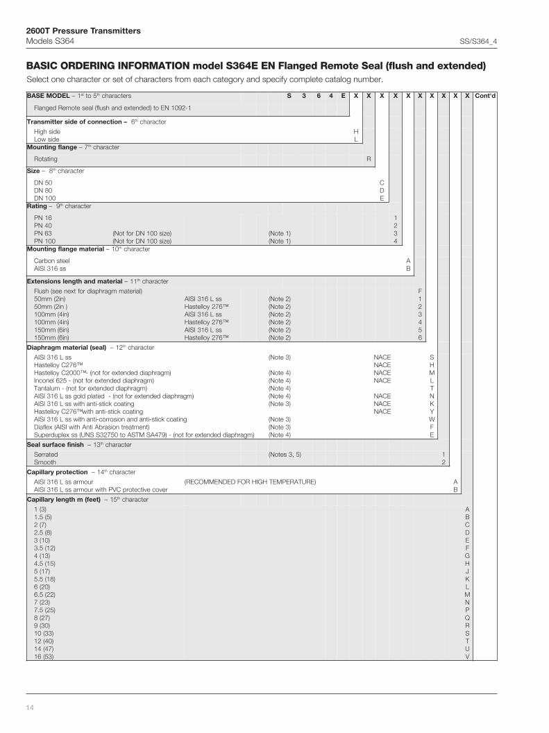
BASIC ORDERING INFORMATION model S364E EN Flanged Remote Seal (flush and extended)Select one character or set of characters from each category and specify complete catalog number.
LEDOMESAB 1– ts 5ot ht sretcarahc S 3 6 4 E X X X X X X X X X X d'tnoC
1-2901NEot)dednetxednahsulf(laesetomeRdegnalF
–noitcennocfoedisrettimsnarT 6 ht retcarahc
edishgiHediswoL
HL
egnalfgnitnuoM 7– ht retcarahc
gnitatoR R
eziS – 8 ht retcarahc
05ND08ND001ND
CDE
gnitaR – 9 ht retcarahc
61NP04NP36NP001NP
)ezis001NDroftoN()ezis001NDroftoN(
)1etoN()1etoN(
1234
lairetamegnalfgnitnuoM 01– ht retcarahc
leetsnobraCss613ISIA
AB
lairetamdnahtgnelsnoisnetxE 11– ht retcarahc
)lairetammgarhpaidroftxenees(hsulF)ni2(mm05)ni2(mm05)ni4(mm001)ni4(mm001)ni6(mm051)ni6(mm051
ssL613ISIA™672yolletsaH
ssL613ISIA™672yolletsaH
ssL613ISIA™672yolletsaH
)2etoN()2etoN()2etoN()2etoN()2etoN()2etoN(
F123456
)laes(lairetammgarhpaiD 21– ht retcarahc
ssL613ISIA™672CyolletsaH
)mgarhpaiddednetxerofton(-™0002CyolletsaH)mgarhpaiddednetxerofton(-526lenocnI
)mgarhpaiddednetxerofton(-mulatnaT)mgarhpaiddednetxerofton(-detalpdlogssL613ISIA
gnitaockcits-itnahtiwssL613ISIAgnitaockcits-itnahtiw™672CyolletsaH
gnitaockcits-itnadnanoisorroc-itnahtiwssL613ISIA)tnemtaertnoisarbAitnAhtiwISIA(xelfaiD
)mgarhpaiddednetxerofton(-)974ASMTSAot05723SSNU(ssxelpudrepuS
)3etoN(
)4etoN()4etoN()4etoN()4etoN()3etoN(
)3etoN()3etoN()4etoN(
ECANECANECANECAN
ECANECANECAN
SHMLTNKYWFE
hsinifecafruslaeS 31– ht retcarahc
detarreShtoomS
)5,3setoN( 12
noitcetorpyrallipaC 41– ht retcarahc
ruomrassL613ISIArevocevitcetorpCVPhtiwruomrassL613ISIA
)ERUTAREPMETHGIHROFDEDNEMMOCER( AB
)teef(mhtgnelyrallipaC 51– ht retcarahc
)3(1)5(5.1
)7(2)8(5.2)01(3
)21(5.3)31(4
)51(5.4)71(5
)81(5.5)02(6
)22(5.6)32(7
)52(5.7)72(8)03(9)33(01)04(21)74(41)35(61
ABCDEFGHJKLMNPQRSTUV

2600T Pressure TransmittersModels S364 SS/S364_4
15
Note 1: Not available with size code E
Note 2: Not available with mounting flange rating code 3, 4
Note 3: Not available with extensions length and material code 2, 4, 6
Note 4: Not available with extensions length and material code 1, 2, 3, 4, 5, 6
Note 5: Not available with diaphragm material code M, L, T, N, K, Y, W and H when selected with extension length and material code F, 2, 4, 6
Note 6: Suitable for oxygen service
Note 7: Suitable for food application
Note 8: Not available with Flushing ring: hole and thread code 2, 3, 4, 5
Note 9: Not available with Flushing ring: hole and thread code N
Note 10: Not available with seat surface finish code 1 (serrated)
Note 11: Not available with Hastelloy C276 flushing ring material code H
Note 12: Not available with AISI 316L flushing ring material code A
E463SNOITAMROFNIGNIREDROCISAB X X X X X
diulflliF 61– ht retcarahc
lioenociliSnedlaG-diulftrenI
nobracolaH-diulftrenIerutarepmethgihroflioenocilIS
erutarepmetwolrofremylopenociliS)devorppaADF(liolareniM
)devorppaADF(lioelbategeV)devorppaADF(retaw-nirecylG
)6etoN()6etoN(
)7etoN()7etoN()7etoN(
SNDGCWAB
noitacifitreC 71– ht retcarahc
enoN 1
daerhtdnaeloh:gnirgnihsulF 81– ht retcarahc
)SNOISREVDEDNETXEROFDETCELESEBOT(enoNTPNni2/1-eloh1TPNni2/1-seloh2
TPNni4/1-eloh1TPNni4/1-seloh2
)4etoN()4etoN()4etoN()4etoN(
N2345
lairetamgnirgnihsulF 91– ht retcarahc
enoNssL613ISIA
672CyolletsaH
)8etoN()9etoN(
)01,9setoN(ECANECAN
NAH
teksagdnagulp:gnirgnihsulF 02– ht retcarahc
teksagon-gulpoNkcolrag-gulpoN
EFTP-gulpoNetihparg-gulpoN
teksagon-ssL613ISIAkcolrag-ssL613ISIA
EFTP-ssL613ISIAetihparg-ssL613ISIA
teksagon-672CyolletsaHkcolrag-672CyolletsaH
EFTP-672CyolletsaHetihparg-672CyolletsaH
)9etoN()9etoN()9etoN(
)11,9setoN()11,9setoN()11,9setoN()11,9setoN()21,9setoN()21,9setoN()21,9setoN()21,9setoN(
NABCDEFGHLMP
2600T Pressure TransmittersModels S364 SS/S364_4
16
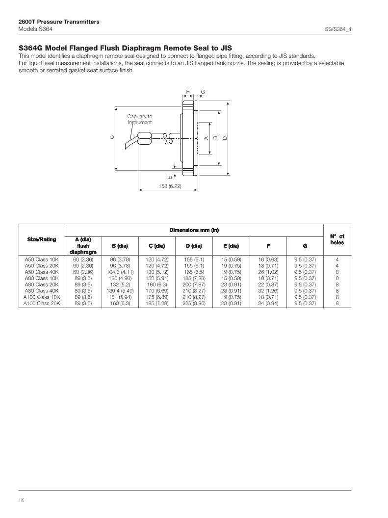
S364G Model Flanged Flush Diaphragm Remote Seal to JISThis model identifies a diaphragm remote seal designed to connect to flanged pipe fitting, according to JIS standards.For liquid level measurement installations, the seal connects to an JIS flanged tank nozzle. The sealing is provided by a selectablesmooth or serrated gasket seat surface finish.
Capillary toInstrument
158 (6.22)
B
F G
C
E
A D
gnitaR/eziS gnitaR/eziS gnitaR/eziS gnitaR/eziS gnitaR/eziS
)ni(mmsnoisnemiD )ni(mmsnoisnemiD )ni(mmsnoisnemiD )ni(mmsnoisnemiD )ni(mmsnoisnemiDfo°N fo°N fo°N fo°N fo°Nseloh seloh seloh seloh seloh)aid(A )aid(A )aid(A )aid(A )aid(A
hsulf hsulf hsulf hsulf hsulfmgarhpaid mgarhpaid mgarhpaid mgarhpaid mgarhpaid
)aid(B )aid(B )aid(B )aid(B )aid(B )aid(C )aid(C )aid(C )aid(C )aid(C )aid(D )aid(D )aid(D )aid(D )aid(D )aid(E )aid(E )aid(E )aid(E )aid(E FFFFF GGGGG
K01ssalC05AK02ssalC05AK04ssalC05AK01ssalC08AK02ssalC08AK04ssalC08AK01ssalC001AK02ssalC001A
)63.2(06)63.2(06)63.2(06)5.3(98)5.3(98)5.3(98)5.3(98)5.3(98
)87.3(69)87.3(69
)11.4(3.401)69.4(621)2.5(231
)94.5(4.931)49.5(151)3.6(061
)27.4(021)27.4(021)21.5(031)19.5(051)3.6(061)96.6(071)98.6(571)82.7(581
)1.6(551)1.6(551)5.6(561)82.7(581)78.7(002)72.8(012)72.8(012)68.8(522
)95.0(51)57.0(91)57.0(91)95.0(51)19.0(32)19.0(32)57.0(91)19.0(32
)36.0(61)17.0(81)20.1(62)17.0(81)78.0(22)62.1(23)17.0(81)49.0(42
)73.0(5.9)73.0(5.9)73.0(5.9)73.0(5.9)73.0(5.9)73.0(5.9)73.0(5.9)73.0(5.9
44888888

2600T Pressure TransmittersModels S364 SS/S364_4
17
Maximum Working Pressure
The pressure limit decreases with increasing temperature above120°C according to JIS B 2220 standards.
Vacuum Service
Full vacuum subject to fill fluid limits. Refer to table A.
Minimum pressure with tantalum diaphragm is 1kPa abs,10mbar abs, 0.15psia.
Process Temperature Limits
Same as fill fluid limits. Refer to table A.
260°C (500°F) for Tantalum diaphragm.
204°C (400°F) for use with Teflon anti-stick coating.
320°C (608°F) for AISI gold plated diaphragm.
Flanged Flush Diaphragm Remote Seal
Gasket seat finish
Smooth : 0.8µm (Ra)
Serrated : 3.2 to 6.3µm (Ra)
Temperature effect
The following table shows the temperature effect for 20K (36°F)change, detailed separately for
a) the seal (one element)
b) the capillary per meter
c) the system (transmitter sensor when combined with a sealof specific size/type)
referred to silicone oil (DC 200) filling and AISI 316 L ss diaphragmmaterials.
For filling different from silicone oil (DC200) the errors can be multipliedby ratio between the thermal expansion coefficients of the selectedfilling divided by the one of DC200, listed in the fill fluid characteristicstable.
THE ERRORS IN TABLE CAN BE CONSIDERED DIVIDED BY 4 FORTRANSMITTERS USING SAME REMOTE SEAL ON THE TWO SIDES
ssalC/gnitaR0222BSIJot
leetSnobraCC°021@
leetSsselniatS613ISIAC°021@
K01 rab41 rab41
K02 rab63 rab63
K04 rab86 rab86
hsulFdegnalFmgarhpaiDeziSlaeS
rorrelaeS rorrEyrallipaCm1 rorrE)rosneS(metsyS
05A Hni61.1,rabm9.2,aPk92.0 2O Hni82.0,rabm7.0,aPk70.0 2O Hni8.0,rabm2,aPk2.0 2O
08A Hni63.0,rabm9.0,aPk90.0 2O Hni21.0,rabm3.0,aPk30.0 2O Hni21.0,rabm3.0,aPk30.0 2O
001A Hni63.0,rabm9.0,aPk90.0 2O Hni21.0,rabm3.0,aPk30.0 2O Hni21.0,rabm3.0,aPk30.0 2O

2600T Pressure TransmittersModels S364 SS/S364_4
18
BASIC ORDERING INFORMATION model S364G Flanged Flush Remote Seal to JISSelect one character or set of characters from each category and specify complete catalog number.
LEDOMESAB 1– ts 5ot ht sretcarahc S 3 6 4 G X X X X X X X X X X d'tnoC
SIJotlaesetomeRhsulFdegnalF
–noitcennocfoedisrettimsnarT 6 ht retcarahc
edishgiHediswoL
HL
egnalfgnitnuoM 7– ht retcarahc
gnitatoR R
eziS – 8 ht retcarahc
05A08A001A
BCD
gnitaR – 9 ht retcarahc
K01K02K04 )1etoN(
246
lairetamegnalfgnitnuoM 01– ht retcarahc
leetsnobraCss613ISIA
AB
lairetamdnahtgnelsnoisnetxE 11– ht retcarahc
)lairetammgarhpaidroftxenees(hsulF F
)laes(lairetammgarhpaiD 21– ht retcarahc
ssL613ISIA™672CyolletsaH™0002CyolletsaH
526lenocnImulatnaT
detalpdlogssL613ISIAgnitaockcits–itnahtiwssL613ISIA
gnitaockcits–itnahtiw™672CyolletsaHgnitaockcits-itnadnanoisorroc-itnahtiwssL613ISIA
)974ASMTSAot05723SSNU(ssxelpudrepuS
ECANECANECANECAN
ECANECANECANECANECAN
SHMLTNKYWE
hsinifecafruslaeS 31– ht retcarahc
detarreShtoomS
)2etoN( 12
noitcetorpyrallipaC 41– ht retcarahc
ruomrassL613ISIArevocevitcetorpCVPhtiwruomrassL613ISIA
)ERUTAREPMETHGIHROFDEDNEMMOCER( AB
)teef(mhtgnelyrallipaC 51– ht retcarahc
)3(1)5(5.1
)7(2)8(5.2)01(3
)21(5.3)31(4
)51(5.4)71(5
)81(5.5)02(6
)22(5.6)32(7
)52(5.7)72(8)03(9)33(01)04(21)74(41)35(61
ABCDEFGHJKLMNPQRSTUV

2600T Pressure TransmittersModels S364 SS/S364_4
19
Note 1: Not available with A100 size code D
Note 2: Not available with diaphragm material code H, M, L, T, N, K, Y, W
Note 3: Suitable for oxygen service
Note 4: Suitable for food application
G463SNOITAMROFNIGNIREDROCISAB X X X X X
diulflliF 61– ht retcarahc
lioenociliSnedlaG-diulftrenI
nobracolaH-diulftrenIerutarepmethgihroflioenocilIS
erutarepmetwolrofremylopenociliS)devorppaADF(liolareniM
)devorppaADF(lioelbategeV)devorppaADF(retaw-nirecylG
)3etoN()3etoN(
)4etoN()4etoN()4etoN(
SNDGCWAB
noitacifitreC 71– ht retcarahc
enoN 1
daerhtdnaeloh:gnirgnihsulF 81– ht retcarahc
)SNOISREVDEDNETXEROFDETCELESEBOT(enoN N
lairetamgnirgnihsulF 91– ht retcarahc
enoN N
teksagdnagulp:gnirgnihsulF 02– ht retcarahc
teksagon-gulpoN N
2600T Pressure TransmittersModels S364 SS/S364_4
20
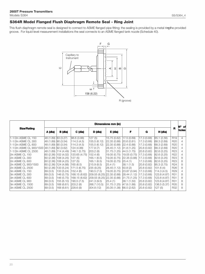
This flush diaphragm remote seal is designed to connect to ASME flanged pipe fitting; the sealing is provided by a metal ring in the providedgroove. For liquid level measurement installations the seal connects to an ASME flanged tank nozzle (Schedule 40).
Capillary toInstrument
158 (6.22)
B
F G
C
E
A DH
gnitaR/eziS gnitaR/eziS gnitaR/eziS gnitaR/eziS gnitaR/eziS
)ni(mmsnoisnemiD )ni(mmsnoisnemiD )ni(mmsnoisnemiD )ni(mmsnoisnemiD )ni(mmsnoisnemiD
RRRRRfo°N fo°N fo°N fo°N fo°Nseloh seloh seloh seloh seloh
)aid(A )aid(A )aid(A )aid(A )aid(A )aid(B )aid(B )aid(B )aid(B )aid(B )aid(C )aid(C )aid(C )aid(C )aid(C )aid(D )aid(D )aid(D )aid(D )aid(D )aid(E )aid(E )aid(E )aid(E )aid(E FFFFF GGGGG )aid(H )aid(H )aid(H )aid(H )aid(H
051LCEMSAni2/1-1003LCEMSAni2/1-1006LCEMSAni2/1-1
0051/009LCEMSAni2/1-10052LCEMSAni2/1-1
051LCEMSAni2003LCEMSAni2006LCEMSAni2
0051/009LCEMSAni20052LCEMSAni2
051LCEMSAni3003LCEMSAni3006LCEMSAni3009LCEMSAni30051LCEMSAni30052LCEMSAni3
)98.1(84)98.1(84)98.1(84)98.1(84)98.1(84)63.2(06)63.2(06)63.2(06)63.2(06)63.2(06
)5.3(98)5.3(98)5.3(98)5.3(98)5.3(98)5.3(98
)72.3(38)45.3(09)45.3(09)26.3(29)94.4(411)20.4(201)52.4(801)52.4(801)88.4(421)42.5(331)42.5(331)57.5(641)57.5(641)01.6(551)16.6(861)16.6(861
)88.3(6.89)5.4(3.411)5.4(3.411
)88.4(421)57.5(1.641)57.4(56.021
)5(721)5(721
)5.6(561)57.6(5.171
)6(4.251)26.6(51.861)26.6(51.861
)5.7(5.091)8(2.302)9(6.822
)5(721)21.6(5.551)21.6(5.551
)7(8.771)8(2.302)6(4.251
)5.6(1.561)5.6(1.561)5.8(9.512
)52.9(532)5.7(5.091
)52.8(55.902)52.8(55.902
)5.9(3.142)5.01(7.662
)21(8.403
)26.0(57.51)88.0(53.22)88.0(53.22)21.1(54.82)52.1(57.13)57.0(50.91)57.0(50.91)57.0(50.91
)1(4.52)21.1(54.82)57.0(50.91)88.0(53.22)88.0(53.22
)1(4.52)52.1(57.13)83.1(50.53
)96.0(5.71)18.0(6.02)88.0(4.22)52.1(8.13)57.1(5.44)57.0(50.91)88.0(53.22
)1(4.52)5.1(1.83
)2(8.05)49.0(78.32)21.1(44.82)52.1(57.13
)05.1(1.83)88.1(8.74)26.2(5.66
)86.0(3.71)86.0(3.71)86.0(3.71)28.0(8.02)28.0(8.02)86.0(3.71)86.0(3.71)86.0(3.71)28.0(8.02)28.0(8.02)86.0(3.71)86.0(3.71)86.0(3.71)28.0(8.02)28.0(8.02)28.0(8.02
)65.2(1.56)96.2(3.86)96.2(3.86)96.2(3.86)52.3(6.28)52.3(6.28)52.3(6.28)52.3(6.28)57.3(3.59
)4(6.101)5.4(3.411)78.4(8.321)78.4(8.321)78.4(8.321)73.5(5.631
)5(721
91R02R02R02R32R22R32R32R42R62R92R13R13R13R53R23R
4444448888488888
S364R Model Flanged Flush Diaphragm Remote Seal - Ring Joint
R (groove)

2600T Pressure TransmittersModels S364 SS/S364_4
21
Maximum Working Pressure
The pressure limit decreases with increasing temperature above100°F (38°C), according to ASME B16.5 standards.
Flanged Flush Diaphragm Remote Seal - Ring Joint
ssalC/gnitaR5.61BEMSAot
leetSnobraC)C°83(F°001@
leetSsselniatS613ISIA)C°83(F°001@
051ssalC isp582 isp572
003ssalC isp047 isp027
006ssalC isp0841 isp0441
009ssalC isp0222 isp0612
0051ssalC isp5073 isp0063
0052ssalC isp0716 isp0006
Vacuum Service
Full vacuum subject to fill fluid limits. Refer to table A.
Process Temperature Limits
Same as fill fluid limits. Refer to table A.
Temperature effect
The following table shows the temperature effect for 20K (36°F)change, detailed separately for
a) the seal (one element)
b) the capillary per meter
c) the system (transmitter sensor when combined with a sealof specific size/type)
referred to silicone oil (DC 200) filling and AISI 316 L ss diaphragmmaterials.
For filling different from silicone oil (DC200) the errors can be multipliedby ratio between the thermal expansion coefficients of the selectedfilling divided by the one of DC200, listed in the fill fluid characteristicstable.
THE ERRORS IN TABLE CAN BE CONSIDERED DIVIDED BY 4 FORTRANSMITTERS USING SAME REMOTE SEAL ON THE TWO SIDES
hsulFdegnalFmgarhpaiD
eziSlaeStnioJgniRrorrelaeS rorrEyrallipaCm1 rorrE)rosneS(metsyS
1 1/2 ni Hni5.3,rabm7.8,aPk78.0 2O Hni2.1,rabm3,aPk3.0 2O Hni6.3,rabm9,aPk9.0 2O
ni2 Hni61.1,rabm9.2,aPk92.0 2O Hni82.0,rabm7.0,aPk70.0 2O Hni8.0,rabm2,aPk2.0 2O
ni3 Hni63.0,rabm9.0,aPk90.0 2O Hni21.0,rabm3.0,aPk30.0 2O Hni21.0,rabm3.0,aPk30.0 2O

2600T Pressure TransmittersModels S364 SS/S364_4
22
BASIC ORDERING INFORMATION model S364R ASME Flanged Remote Seal - Ring JointSelect one character or set of characters from each category and specify complete catalog number.
LEDOMESAB 1– ts 5ot ht sretcarahc S 3 6 4 R X X X X X X X X X X d'tnoC
5.61BEMSAottniojgniRlaesetomeRdegnalF
–noitcennocfoedisrettimsnarT 6 ht retcarahc
edishgiHediswoL
HL
egnalfgnitnuoM 7– ht retcarahc
gnitatoR R
eziS – 8 ht retcarahc
ni2/1-1ni2ni3
BCD
gnitaR – 9 ht retcarahc
051LCEMSA003LCEMSA006LCEMSA009LCEMSA
0051LCEMSA0052LCEMSA
123456
lairetamegnalfgnitnuoM 01– ht retcarahc
leetsnobraCss613ISIA
AB
lairetamdnahtgnelsnoisnetxE 11– ht retcarahc
)lairetammgarhpaidroftxenees(hsulF F
lairetammgarhpaiD 21– ht retcarahc
ssL613ISIA™672CyolletsaH
526lenocnI
ECANECANECAN
SHL
hsinifecafruslaeS 31– ht retcarahc
tniojgniR 3
noitcetorpyrallipaC 41– ht retcarahc
ruomrassL613ISIArevocevitcetorpCVPhtiwruomrassL613ISIA
)ERUTAREPMETHGIHROFDEDNEMMOCER( AB
)teef(mhtgnelyrallipaC 51– ht retcarahc
)3(1)5(5.1
)7(2)8(5.2)01(3
)21(5.3)31(4
)51(5.4)71(5
)81(5.5)02(6
)22(5.6)32(7
)52(5.7)72(8)03(9
)33(01)04(21)74(41)35(61
ABCDEFGHJKLMNPQRSTUV

2600T Pressure TransmittersModels S364 SS/S364_4
23
Note 1: Suitable for oxygen service
Note 2: Suitable for food application
R463SNOITAMROFNIGNIREDROCISAB X X X X X
diulflliF 61– ht retcarahc
lioenociliSnedlaG-diulftrenI
nobracolaH-diulftrenIerutarepmethgihroflioenocilIS
erutarepmetwolrofremylopenociliS)devorppaADF(liolareniM
)devorppaADF(lioelbategeV)devorppaADF(retaw-nirecylG
)1etoN()1etoN(
)2etoN()2etoN()2etoN(
SNDGCWAB
noitacifitreC 71– ht retcarahc
enoN 1
daerhtdnaeloh:gnirgnihsulF 81– ht retcarahc
dettiftoN N
lairetamgnirgnihsulF 91– ht retcarahc
enoN N
teksagdnagulp:gnirgnihsulF 02– ht retcarahc
enoN N
2600T Pressure TransmittersModels S364 SS/S364_4
24
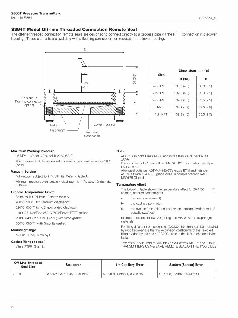
S364T Model Off-line Threaded Connection Remote SealThe off-line threaded connection remote seals are designed to connect directly to a process pipe via the NPT connection in the lowerhousing . These elements are available with a flushing connection, on request, in the lower housing.
Maximum Working Pressure
16 MPa, 160 bar, 2320 psi @ 20°C (68°F)
The pressure limit decreases with increasing temperature above 20°C(68°F)
Vacuum Service
Full vacuum subject to fill fluid limits. Refer to table A.
Minimum pressure with tantalum diaphragm is 1kPa abs, 10mbar abs,0.15psia.
Process Temperature Limits
Same as fill fluid limits. Refer to table A.
260°C (500°F) for Tantalum diaphragm
320°C (608°F) for AISI gold plated diaphragm
–100°C (–148°F) to 260°C (500°F) with PTFE gasket
–20°C (-4°F) to 200°C (392°F) with Viton gasket
360°C (680°F) with Graphite gasket
Mounting flange
AISI 316 L ss, Hastelloy C
Gasket (flange to seal)
Viton, PTFE, Graphite
Bolts
AISI 316 ss bolts Class A4-80 and nuts Class A4-70 per EN ISO3506;Carbon steel bolts Class 8.8 per EN ISO 4014 and nuts Class 8 perEN ISO 898/2;Alloy steel bolts per ASTM-A-193-77a grade B7M and nuts perASTM A194/A 194 M-90 grade 2HM, in compliance with NACEMR0175 Class II.
Temperature effect
The following table shows the temperature effect for 20K (36 °F)change, detailed separately for
a) the seal (one element)
b) the capillary per meter
c) the system (transmitter sensor when combined with a seal ofspecific size/type)
referred to silicone oil (DC 200) filling and AISI 316 L ss diaphragmmaterials.
For filling different from silicone oil (DC200) the errors can be multipliedby ratio between the thermal expansion coefficients of the selectedfilling divided by the one of DC200, listed in the fill fluid characteristicstable.
THE ERRORS IN TABLE CAN BE CONSIDERED DIVIDED BY 4 FORTRANSMITTERS USING SAME REMOTE SEAL ON THE TWO SIDES
Gasket
DiaphragmProcess
Connection
Lower Housing
1/4in NPT-fFlushing connection
(option)
dedaerhTeniL-ffOeziSlaeS
rorrelaeS rorrEyrallipaCm1 rorrE)rosneS(metsyS
2 1/2 ni Hni82.1,rabm2.3,aPk23.0 2O Hni27.0,rabm8.1,aPk81.0 2O Hni6.0,rabm5.1,aPk51.0 2O
Q
D
134
(5.3
) eziS)ni(mmsnoisnemiD
)aid(D Q
1/4 TPNni )3.4(2.901 )1.2(3.35
1/2 TPNni )3.4(2.901 )1.2(3.35
3/4 TPNni )3.4(2.901 )5.2(5.36
TPNni1 )3.4(2.901 )5.2(5.36
1 1/2 TPNni )3.4(2.901 )5.2(5.36

2600T Pressure TransmittersModels S364 SS/S364_4
25
BASIC ORDERING INFORMATION model S364T Off-Line Threaded Connection Remote Seal
Note 1: Suitable for oxygen service
Note 2: Suitable for food application
Note 3: Not available with Size code 4
Select one character or set of characters from each category and specify complete catalog number.
LEDOMESAB 1– ts 5ot ht sretcarahc S 3 6 4 T X X X X X X X X X X
laesetomerdedaerhtenil-ffO
–noitcennocfoedisrettimsnarT 6 ht retcarahcedishgiHediswoL
HL
eziS 7– ht retcarahc1/4 f-TPNni1/2 f-TPNni3/4 f-TPNni
f-TPNni1-1 1/2 f-TPNni
12534
stloB – 8 ht retcarahc
ss613ISIAleetsnobraC
leetsyollA ECAN
123
lairetamegnalF 9– ht retcarahc
ssL613ISIA™672CyolletsaH
ECANECAN
12
lairetammgarhpaiD 01– ht retcarahc
ssL613ISIA™672CyolletsaH
™0002CyolletsaH526lenocnI
mulatnaTdetalpdlogssL613ISIA
ECANECANECANECAN
SHMLTN
noitcetorpyrallipaC 11– ht retcarahc
ruomrassL613ISIArevocevitcetorpCVPhtiwruomrassL613ISIA
)ERUTAREPMETHGIHROFDEDNEMMOCER( AB
)teef(mhtgnelyrallipaC 21– ht retcarahc
)3(1)5(5.1
)7(2)8(5.2
)01(3)21(5.3
)31(4)51(5.4
)71(5)81(5.5
)02(6)22(5.6
)32(7)52(5.7
)72(8)03(9
ABCDEFGHJKLMNPQR
diulflliF 31– ht retcarahc
lioenociliSnedlaG-diulftrenI
nobracolaH-diulftrenIerutarepmethgihroflioenocilIS
erutarepmetwolrofremylopenociliS)devorppaADF(liolareniM
)devorppaADF(lioelbategeV)devorppaADF(retaw-nirecylG
)1etoN()1etoN(
)2etoN()2etoN()2etoN(
SNDGCWAB
snoitcennocgnihsulF 41– ht retcarahc
deriuqertoNdedivorP )3etoN(
1Q
teksaG 51– ht retcarahc
EFTP™notiV
etihparG
237
2600T Pressure TransmittersModels S364 SS/S364_4
26
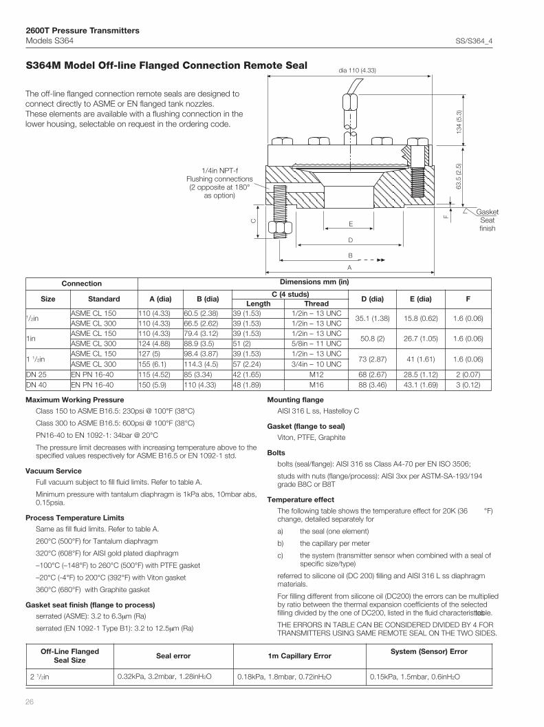
The off-line flanged connection remote seals are designed toconnect directly to ASME or EN flanged tank nozzles.These elements are available with a flushing connection in thelower housing, selectable on request in the ordering code.
Maximum Working Pressure
Class 150 to ASME B16.5: 230psi @ 100°F (38°C)
Class 300 to ASME B16.5: 600psi @ 100°F (38°C)
PN16-40 to EN 1092-1: 34bar @ 20°C
The pressure limit decreases with increasing temperature above to thespecified values respectively for ASME B16.5 or EN 1092-1 std.
Vacuum Service
Full vacuum subject to fill fluid limits. Refer to table A.
Minimum pressure with tantalum diaphragm is 1kPa abs, 10mbar abs,0.15psia.
Process Temperature Limits
Same as fill fluid limits. Refer to table A.
260°C (500°F) for Tantalum diaphragm
320°C (608°F) for AISI gold plated diaphragm
–100°C (–148°F) to 260°C (500°F) with PTFE gasket
–20°C (-4°F) to 200°C (392°F) with Viton gasket
360°C (680°F) with Graphite gasket
Gasket seat finish (flange to process)
serrated (ASME): 3.2 to 6.3µm (Ra)
serrated (EN 1092-1 Type B1): 3.2 to 12.5µm (Ra)
Mounting flange
AISI 316 L ss, Hastelloy C
Gasket (flange to seal)
Viton, PTFE, Graphite
Bolts
bolts (seal/flange): AISI 316 ss Class A4-70 per EN ISO 3506;
studs with nuts (flange/process): AISI 3xx per ASTM-SA-193/194grade B8C or B8T
Temperature effect
The following table shows the temperature effect for 20K (36 °F)change, detailed separately for
a) the seal (one element)
b) the capillary per meter
c) the system (transmitter sensor when combined with a seal ofspecific size/type)
referred to silicone oil (DC 200) filling and AISI 316 L ss diaphragmmaterials.
For filling different from silicone oil (DC200) the errors can be multipliedby ratio between the thermal expansion coefficients of the selectedfilling divided by the one of DC200, listed in the fluid characteristics table.
THE ERRORS IN TABLE CAN BE CONSIDERED DIVIDED BY 4 FORTRANSMITTERS USING SAME REMOTE SEAL ON THE TWO SIDES.
1/4in NPT-fFlushing connections(2 opposite at 180°
as option)
GasketSeatfinish
degnalFeniL-ffOeziSlaeS
rorrelaeS rorrEyrallipaCm1rorrE)rosneS(metsyS
2 1/2 ni Hni82.1,rabm2.3,aPk23.0 2O Hni27.0,rabm8.1,aPk81.0 2O Hni6.0,rabm5.1,aPk51.0 2O
63.5
(2.5
)
dia 110 (4.33)
B
E
D
F
A
C
134
(5.3
)
S364M Model Off-line Flanged Connection Remote Seal
noitcennoC )ni(mmsnoisnemiD
eziS dradnatS )aid(A )aid(B)sduts4(C
)aid(D )aid(E FhtgneL daerhT
1/2 ni051LCEMSA )33.4(011 )83.2(5.06 )35.1(93 CNU31–ni2/1
)83.1(1.53 )26.0(8.51 )60.0(6.1003LCEMSA )33.4(011 )26.2(5.66 )35.1(93 CNU31–ni2/1
ni1051LCEMSA )33.4(011 )21.3(4.97 )35.1(93 CNU31–ni2/1
)2(8.05 )50.1(7.62 )60.0(6.1003LCEMSA )88.4(421 )5.3(9.88 )2(15 CNU11–ni8/5
1 1/2 ni051LCEMSA )5(721 )78.3(4.89 )35.1(93 CNU31–ni2/1
)78.2(37 )16.1(14 )60.0(6.1003LCEMSA )1.6(551 )5.4(3.411 )42.2(75 CNU01–ni4/3
52ND 04-61NPNE )25.4(511 )43.3(58 )56.1(24 21M )76.2(86 )21.1(5.82 )70.0(204ND 04-61NPNE )9.5(051 )33.4(011 )98.1(84 61M )64.3(88 )96.1(1.34 )21.0(3

2600T Pressure TransmittersModels S364 SS/S364_4
27
BASIC ORDERING INFORMATION model S364M Off-line Flanged Connection Remote SealSelect one character or set of characters from each category and specify complete catalog number.
Note 1: Not available with EN mounting flange code M, N
Note 2: Not available with ASME mounting flange code A, B, C, D, 6, 7
Note 3: Suitable for oxygen service
Note 4: Suitable for food application
LEDOMESAB 1– ts 5ot ht sretcarahc S 3 6 4 M X X X X X X X X X X
laesetomerdegnalf-inimenil-ffO
–noitcennocfoedisrettimsnarT 6 ht retcarahcedishgiHediswoL
HL
egnalfgnitnuoM 7– ht retcarahclaeshtiwlargetnI P
gnitaregnalfgnitnuoM/eziS – 8 ht retcarahc
1/2 ni1/2 ni
ni1ni1
1 1/2 ni1 1/2 ni
52ND04ND
051LCEMSA003LCEMSA051LCEMSA003LCEMSA051LCEMSA003LCEMSA
04/61NPNE04/61NPNE
67ACBDMN
)laes(mroftaeS/egnalfgnitnuoM 9– ht retcarahc
ssL613ISIAssL613ISIA
™672CyolletsaH™672CyolletsaH
hsinifdetarres–)ecafdesiar(FRmroFhsinifdetarres–1BepyT1-2901NE
hsinifdetarres–)ecafdesiar(FRmroFhsinifdetarres–1BepyT1-2901NE
)1etoN()2etoN()1etoN()2etoN(
ECANECANECANECAN
DLUV
)laes(lairetammgarhpaiD 01– ht retcarahc
ssL613ISIA™672CyolletsaH
™0002CyolletsaH526lenocnI
mulatnaTdetalpdlogssL613ISIA
ECANECANECANECAN
SHMLTN
noitcetorpyrallipaC 11– ht retcarahc
ruomrassL613ISIArevocevitcetorpCVPhtiwruomrassL613ISIA
)ERUTAREPMETHGIHROFDEDNEMMOCER( AB
)teef(mhtgnelyrallipaC 21– ht retcarahc
)3(1)5(5.1
)7(2)8(5.2
)01(3)21(5.3
)31(4)51(5.4
)71(5)81(5.5
)02(6)22(5.6
)32(7)52(5.7
)72(8)03(9
ABCDEFGHJKLMNPQR
diulflliF 31– ht retcarahc
lioenociliSnedlaG-diulftrenI
nobracolaH-diulftrenIerutarepmethgihroflioenocilIS
erutarepmetwolrofremylopenociliS)devorppaADF(liolareniM
)devorppaADF(lioelbategeV)devorppaADF(retaw-nirecylG
)3etoN()3etoN(
)4etoN()4etoN()4etoN(
SNDGCWAB
snoitcennocgnihsulF 41– ht retcarahc
deriuqertoNdedivorP
1Q
teksaG 51– ht retcarahc
EFTP™notiV
etihparG
237
2600T Pressure TransmittersModels S364 SS/S364_4
28
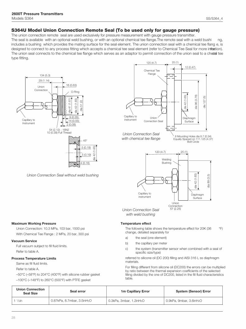
S364U Model Union Connection Remote Seal (To be used only for gauge pressure)The union connection remote seal are used exclusively for pressure measurement with gauge pressure transmitter.The seal is available with an optional weld bushing, or with an optional chemical tee flange.The remote seal with a weld bushi ng,includes a bushing which provides the mating surface for the seal element. The union connection seal with a chemical tee flang e, isdesigned to connect to any process fitting which accepts a chemical tee seal element (refer to Chemical Tee Seal for more information).The union seal connects to the chemical tee flange which serves as an adaptor to permit connection of the union seal to a chemical teetype fitting.
Maximum Working Pressure
Union Connection: 10.3 MPa, 103 bar, 1500 psi
With Chemical Tee Flange : 2 MPa, 20 bar, 300 psi
Vacuum Service
Full vacuum subject to fill fluid limits.
Refer to table A.
Process Temperature Limits
Same as fill fluid limits.
Refer to table A.
–50°C (–58°F) to 204°C (400°F) with silicone rubber gasket
–100°C (–148°F) to 260°C (500°F) with PTFE gasket
Temperature effect
The following table shows the temperature effect for 20K (36 °F)change, detailed separately for
a) the seal (one element)
b) the capillary per meter
c) the system (transmitter sensor when combined with a seal ofspecific size/type)
referred to silicone oil (DC 200) filling and AISI 316 L ss diaphragmmaterials.
For filling different from silicone oil (DC200) the errors can be multipliedby ratio between the thermal expansion coefficients of the selectedfilling divided by the one of DC200, listed in the fill fluid characteristicstable.
Capillary toinstrument
DiaphragmSurface
WeldingBushing
Capillary toInstrument
Capillary toinstrument
UnionConnection Seal
UnionConnection
DiaphragmSurface
Chemical TeeFlange
O-Ring
noitcennoCnoinUeziSlaeS
rorrelaeS rorrEyrallipaCm1 rorrE)rosneS(metsyS
1 1/2 ni Hni5.3,rabm7.8,aPk78.0 2O Hni2.1,rabm3,aPk3.0 2O Hni6.3,rabm9,aPk9.0 2O
Union Connection Seal without weld bushing
Union Connection Sealwith chemical tee flange
Union Connection Sealwith weld bushing
120 (4.7) 25 (1)
dia
42 (1
.65)
dia
89 (3
.5)
UnionConnection
57 (2.25)
120 (4.7) 25 (1)
12 (0.47)
dia
96 (3
.78)
dia
42 (1
.65)
dia
127
(5)
8 Mounting Holes dia 8.7 (0.34)Equally Spaced on 111.125 (4.37)
Bolt Circle
dia
41 (1
.61)
dia
42 (1
.65)
dia
51 (2
) 29 (1.14)
134 (5.3)
16 (0.63)
9 (0.35)14 (0.55)
45°
5 (0.19)
5 (0.19)
4 (0.16)
dia
42 (1
.65)
2 (0.08)
54 (2.12) - 16N210 (0.39) Full Thread
2600T Pressure TransmittersModels S364 SS/S364_4
29
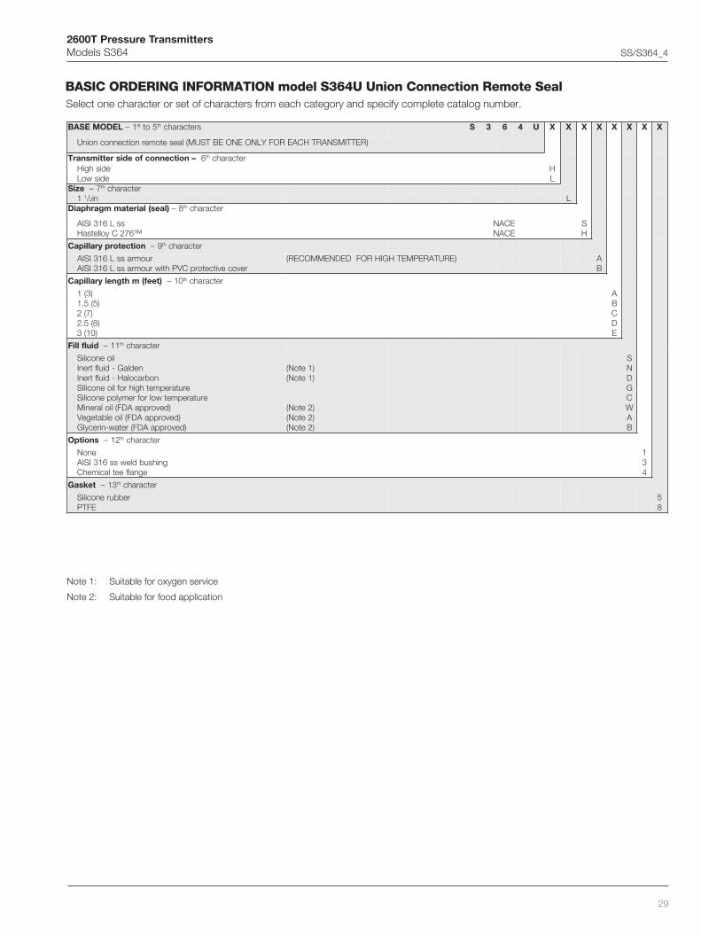
BASIC ORDERING INFORMATION model S364U Union Connection Remote SealSelect one character or set of characters from each category and specify complete catalog number.
Note 1: Suitable for oxygen service
Note 2: Suitable for food application
LEDOMESAB 1– ts 5ot ht sretcarahc S 3 6 4 U X X X X X X X X
)RETTIMSNARTHCAEROFYLNOENOEBTSUM(laesetomernoitcennocnoinU
–noitcennocfoedisrettimsnarT 6 ht retcarahcedishgiHediswoL
HL
eziS 7– ht retcarahc1 1/2 ni L
)laes(lairetammgarhpaiD 8– ht retcarahc
ssL613ISIA™672CyolletsaH
ECANECAN
SH
noitcetorpyrallipaC 9– ht retcarahc
ruomrassL613ISIArevocevitcetorpCVPhtiwruomrassL613ISIA
)ERUTAREPMETHGIHROFDEDNEMMOCER( AB
)teef(mhtgnelyrallipaC 01– ht retcarahc
)3(1)5(5.1
)7(2)8(5.2
)01(3
ABCDE
diulflliF 11– ht retcarahc
lioenociliSnedlaG-diulftrenI
nobracolaH-diulftrenIerutarepmethgihroflioenocilIS
erutarepmetwolrofremylopenociliS)devorppaADF(liolareniM
)devorppaADF(lioelbategeV)devorppaADF(retaw-nirecylG
)1etoN()1etoN(
)2etoN()2etoN()2etoN(
SNDGCWAB
snoitpO 21– ht retcarahc
enoNgnihsubdlewss613ISIA
egnalfeetlacimehC
134
teksaG 31– ht retcarahc
rebburenociliSEFTP
58

2600T Pressure TransmittersModels S364 SS/S364_4
30
S364S Food and Sanitary Remote SealsThe Union Nut and Triclamp remote seals are designed for connection by Union Nut according to DIN 11851 - F50 or F80 and 2 in,3 in, 4 in Triclamp sanitary fittings. A variety of gaskets and clamp rings for the seals are available.
pmalcirT
ni2 ni3 ni4
)aid(A )2.2(3.65 )62.3(38 )43.4(3.011
)aid(B )5.2(46 )85.3(19 86.4(911
Union Nut Seal (to DIN 11851)
Triclamp Seal
The Cherry Burrell remote seals are designed for connection to 2in, 3in or 4in Cherry Burrell I-Line sanitary fittings. A 4in V-bandclamp is optionally available for the 4in variant.
tuNnoinU
05F 08F
)aid(A )86.2(86 )39.3(001
)DR(B )70.3(87 )33.4(011
C )36.0(61 )47.0(91
A
B
C13
4 (5
.3)
27 (1
.06)A
B
20
(0.7
9)
2.8
5 (0
.11)
134
(5.3
)
E
FH
G
B
A
C
D
eziS)ni(mmSNOISNEMID
)aid(A )aid(B )aid(C )aid(D E F G H
ni2 )46.2(76 )2.2(65 )56.1(24 )42.2(75 )31.0(2.3 )62.0(5.6 )94.0(5.21 )21.0(3
ni3 )78.3(4.89 )91.3(18 )58.2(24.27 )3.3(8.38 )90.0(4.2 )13.0(9.7 )95.0(51 )21.0(3
ni4 )88.4(421 )83.4(52.111 )58.2(24.27 )3.4(3.901 90.0(4.2 )13.0(9.7 )95.0(51 )21.0(3
Note: seal model not3-A authorized

2600T Pressure TransmittersModels S364 SS/S364_4
31
The sanitary remote seal with flush diaphragm is designed to connect to a 4in sanitary tank spud. The tank spud and process gasketare available as options with the seal suitable V-band clamp is also available on request.NOTE: The tank spud required for connection of this seal element must be welded to the process vessel prior to connecting the seal,following a recommended welding and pressure testing procedure.
The sanitary remote seal with extended diaphragm is designed to connect to a 4in sanitary tank spud. The tank spud and processgasket are available with the seal.NOTE: The tank spud required for connection of this seal element must be welded to the process vessel prior to connecting the seal,following a recommended welding and pressure testing procedure.
eziS)ni(mmsnoisnemiD
A
ni2 )1.2(3.35
ni4 )1.4(1.401
ni6 )1.6(9.451
dia 72 (2.83)
dia 110 (4.33)
dia 152.4 (6)
19.3
(0.7
5)
18.5
(0.7
2)
8 (0
.31)
for
thin
wal
l
13 (0
.51)
for
thic
k w
all
dia 119 (4.68)
dia 85.5 (3.36)dia 36 (1.41)
dia 72 (2.83)dia 100 (3.93)dia 152 (5.98)
A10
(0.3
9)
5.6
(0.2
2)
dia 132.6 (5.22)

2600T Pressure TransmittersModels S364 SS/S364_4
32
The sanitary aseptic remote seal is designed to connect to a 4in sanitary fitting: either an aseptic tank spud or a 4in Cherry Burrellaseptic ferrule. The tank spud, gaskets and V-band clamp are available option with the seal element.NOTE: The tank spud or ferrule required for connection of this seal element must be welded to the process vessel prior toconnecting the element, following recommended welding and pressure testing procedure. Weld the Cherry Burrell ferrule to theprocess vessel in accordance with manufacturers recommandations.
4in Aseptic Flanged Connection
4in Cherry Burrell Aseptic
Maximum Working Pressure @ 20°C (68°F)
2 in Triclamp : 3.8 MPa, 38 bar, 550 psi
3 in Triclamp : 2.4 MPa, 24 bar, 350 psi
4 in Triclamp : 1.7 MPa, 17 bar, 250 psi
F50/F80 Union nut : 2.5 MPa, 25 bar, 360 psi
Cherry Burrell: 1.9MPa, 19bar, 275psi
4in Sanitary flush or extended or aseptic: 1.9MPa, 19bar, 275psi
4in V-band clamp option: 1MPa, 10bar, 145psi
4in schedule 5 V-band clamp option: 0.7MPa, 7bar, 100psi @ 21°C.
Process Temperature Limits
Same as fill fluid limits. Refer to table A.
Process Gasket Temperature Limits
Ethylene Propylene EPDM 3-A 18-03 Class II:–40 to 121°C (–40 to 250°F)
Ethylene Propylene: –40 to149°C (–40 to 300°F)
Vacuum Service
Full vacuum subject to fill fluid limits. Refer to table A.
Temperature effect
The following table shows the temperature effect for 20K (36 °F)change, detailed separately for
a) the seal (one element)
b) the capillary per meter
c) the system (transmitter sensor when combined with a seal ofspecific size/type)
referred to silicone oil (DC 200) filling and AISI 316 L ss diaphragmmaterials.
For filling different from silicone oil (DC200) the errors can be multipliedby ratio between the thermal expansion coefficients of the selectedfilling divided by the one of DC200, listed in the fill fluid characteristicstable.
THE ERRORS IN TABLE CAN BE CONSIDERED DIVIDED BY 4 FORTRANSMITTERS USING SAME REMOTE SEAL ON THE TWO SIDES
,llerruByrrehC,pmalcirT,tuNnoinUeziSlaeScitpesAdnayratinaS
rorrelaeS rorrEyrallipaCm1 rorrE)rosneS(metsyS
05F/ni2 Hn8.2,rabm7,aPk7.0 2O Hni7.1,rabm2.4,aPk24.0 2O Hni6.5,rabm41,aPk4.1 2O
08F/ni3 Hni42.0,rabm6.0,aPk60.0 2O Hni21.0,rabm3.0,aPk30.0 2O Hni21.0,rabm3.0,aPk30.0 2O
ni4 Hni42.0,rabm6.0,aPk60.0 2O Hni21.0,rabm3.0,aPk30.0 2O Hni21.0,rabm3.0,aPk30.0 2O
2 holes 1/8in–27NPT(180° symmetrical for steam connection)
dia 119 (4.68)
dia 105 (4.13)
dia 85.5 (3.36)
dia 79.6 (3.13)dia 62 (2.44)
4.2
(0.1
6)
19.3
(0.7
5)
11.2
(0.7
5)
dia 72.4 (2.85)
dia 82.6 (3.25)
dia 111.25 (4.37)
dia 124 (4.88)
2.4
(0.0
9)
7.9
(0.3
1)3
(0.1
1)
15 (0
.59)

2600T Pressure TransmittersModels S364 SS/S364_4
33
BASIC ORDERING INFORMATION model S364S Food and Sanitary Remote SealsSelect one character or set of characters from each category and specify complete catalog number.
Note 1: Union nut DIN 11851 (F50 and F80) are not 3-A authorized models
Note 2: Suitable for food application
LEDOMESAB 1– ts 5ot ht sretcarahc S 3 6 4 S X X X X X X X X
slaesetomeryratinaSdnadooF
–noitcennocfoedisrettimsnarT 6 ht retcarahcedishgiHediswoL
HL
noitcennocgnitnuoM 7– ht retcarahc05F–15811NIDtunnoinU08F–15811NIDtunnoinU
pmalcirTni2pmalcirTni3pmalcirTni4
llerruByrrehCni2llerruByrrehCni3llerruByrrehCni4
mgarhpaidhsulfyratinaSni4mgarhpaid)ni2(dednetxeyratinaSni4mgarhpaid)ni4(dednetxeyratinaSni4mgarhpaid)ni6(dednetxeyratinaSni4
citpesallerruByrrehCni4noitcennocdegnalfcitpesani4
)1etoN()1etoN(
ABFGHLMNPQRSWJ
lairetammgarhpaidlaeS – 8 ht retcarahc
ssL613ISIA S
noitcetorpyrallipaC 9– ht retcarahc
ruomrassL613ISIArevocevitcetorpCVPhtiwruomrassL613ISIA
)ERUTAREPMETHGIHROFDEDNEMMOCER( AB
)teef(mhtgnelyrallipaC 01– ht retcarahc
)3(1)5(5.1
)7(2)8(5.2
)01(3)21(5.3
)31(4)51(5.4
)71(5)81(5.5
)02(6)22(5.6
)32(7)52(5.7
)72(8)03(9
)33(01
ABCDEFGHJKLMNPQRS
diulflliF 11– ht retcarahc
lioenociliS)devorppaADF(liolareniM
)devorppaADF(lioelbategeV)devorppaADF(retaw-nirecylG
)2etoN()2etoN()2etoN(
SWAB
sgnittiF/pmalC 21– ht retcarahc
enoN)pmalcirTni2rof(pmalCdnab-Vni2)pmalcirTni3rof(pmalCdnab-Vni3
)degnalfcitpesani4dnahsulfyratinaSni4,llerruByrrehCni4,pmalcirTni4rof(pmalCdnab-Vni4)laeshsulfyratinaSni4rof(pmalCdnab-Vni4dna)81.0(mm7.4otpullawknat,dupsknaTni4)laeshsulfyratinaSni4rof(pmalCdnab-Vni4dna)73.0(mm5.9otpullawknat,dupsknaTni4
)laesdednetxeyratinaSni4rof(pmalcdnab-V5eludehcsni4)laesni2dednetxeyratinaSni4rof(pmalcdnab-V5eludehcsni4dnanoisnetxeni2rofdupsknaT)laesni4dednetxeyratinaSni4rof(pmalcdnab-V5eludehcsni4dnanoisnetxeni4rofdupsknaT)laesni6dednetxeyratinaSni4rof(pmalcdnab-V5eludehcsni4dnanoisnetxeni6rofdupsknaT
)laesdegnalfcitpesani4rof(dupsknatcitpesA
1ABCDEFGHJP
teksaG 31– ht retcarahc
enoN)IIssalC30-81A-3MDPE(-)laesdednetxeyratinaSni4rof(001NDteksagenelyporpenelyhtE
)laestunnoinU05Frof(05NDteksagenelyporpenelyhtE)laestunnoinU08Frof(08NDteksagenelyporpenelyhtE
)IIssalC30-81A-3MDPE(-)laesdegnalfcitpesadnahsulfyratinaSni4rof(teksagenelyporpenelyhtE
1ACDG

2600T Pressure TransmittersModels S364 SS/S364_4
34

2600T Pressure TransmittersModels S364 SS/S364_4
35

DS
/S36
4-E
N R
ev.
D 1
2.20
10ABB Ltd. Process AutomationHoward RoadSt. NeotsCambridgeshire PE19 8EU UKTel: +44 (0)1480 475321Fax: +44 (0)1480 217948
ABB Inc.Process Automation125 E. County Line RoadWarminster PA 18974USATel: +1 215 674 6000Fax: +1 215 674 7183
ABB Automation Products GmbHProcess AutomationSchillerstr. 7232425 MindenGermanyTel: +49 551 905 534Fax: +49 551 905 555
ABB S.p.A. Process AutomationVia Statale 11322016 Lenno (CO)ItalyTel: +39 0344 58111Fax: +39 0344 56278
www.abb.com
Contact us
NoteWe reserve the right to make technical changes or modify the contents of this document without prior notice. With regard to purchase orders, the agreedparticulars shall prevail. ABB does not accept any responsibility whatsoever for potential errors or possible lack of information in this document.
We reserve all rights in this document and in the subject matter and illustrations contained therein. Any reproduction, disclosure to third parties or utilization of its contents - in whole or in parts – is forbidden without prior written consent of ABB.
Copyright© 2010 ABBAll rights reserved
™ Hastelloy C276 is a Cabot Corporation trademark™ Hastelloy C2000 is an Haynes International trademark™ Monel is an International Nickel Co. trademark™ Viton is a Dupont de Nemour trademark™ DC200 and DC704 are Dow Corning Corpora-tion trademarks™ Galden is a Montefluos trademark™ Halocarbon is a Halocarbon Products Co. trademark™ Neobee M20 is a Stepan Company trademark™ Marcol is a Esso Italiana trademark™ Syltherm is a Dow Chemical Company trademark