Embed Size (px)
Citation preview

EVERLIGHT ELECTRONICS CO.,LTD.
Everlight Electronics Co., Ltd. http://www.everlight.com Rev. 2 Page: 1 of 9
Device No. : prepared date:28-Sep-2006 Prepared by:Rita Shen
Technical Data Sheet (Preliminary) Power Top View LED
67-31AUBC/B001/TR8 Features
․P-LCC-3 package. ․High flux output. ․High current capability. ․White package. ․Optical indicator. ․Colorless clear window. ․Ideal for backlight and light pipe application. ․Inter reflector. ․Wide viewing angle. ․Suitable for automatic placement equipment. ․Suitable for reflow and wave solder processes. ․Available on tape and reel (8mm Tape). ․Pb-free. ․The product itself will remain within RoHS compliant version.
Descriptions The 67-31A series is available in soft orange, red and yellow. Due to the package design, the LED has wide viewing angle and optimized light coupling by inter reflector. This feature makes the ideal for light pipe application. The low current requirement makes this device ideal for portable equipment or any other application where power is at a premium.
Applications ․Indicator and backlight for audio and video equipment. ․Indicator and backlight in office and family equipment. ․Flat backlight for LCD’s, switches and symbols. ․Light pipe application. ․General use.
Device Selection Guide
Chip
Material Emitted Color Lens Color
InGaN/SiC Blue Water Clear

EVERLIGHT ELECTRONICS CO.,LTD.
Everlight Electronics Co., Ltd. http://www.everlight.com Rev. 2 Page: 2 of 9
Device No. : prepared date:28-Sep-2006 Prepared by:Rita Shen
67-31AUBC/B001/TR8
Package Dimensions
Note: The tolerances unless mentioned is ±0.1mm ;Unit = mm

EVERLIGHT ELECTRONICS CO.,LTD.
Everlight Electronics Co., Ltd. http://www.everlight.com Rev. 2 Page: 3 of 9
Device No. : prepared date:28-Sep-2006 Prepared by:Rita Shen
67-31AUBC/B001/TR8
Absolute Maximum Ratings (TA=25℃) Parameter Symbol Rating Unit
Reverse Voltage VR 5 V
Forward Current IF 30 mA
Peak Forward Current (Duty 1/10 @1KHz) IFP 100 mA
Power Dissipation Pd 120 mW
Junction Temperature Tj 125 ℃
Electrostatic Discharge(HBM) ESD 2000 V
Operating Temperature Topr -40 ~ +100 ℃
Storage Temperature Tstg -40~ +110 ℃
Soldering Temperature Tsol Reflow Soldering : 260 ℃ for 10 sec. Hand Soldering : 350 ℃ for 3 sec.
Electronic Optical Characteristics :
Parameter Symbol Min. Typ. Max. Unit Condition
Luminous Intensity Iv 140 ----- 285 mcd IF=30mA
Viewing Angle 2θ1/2 ----- 120 ----- deg IF=30mA
Peak Wavelength λP ----- 468 ----- nm IF=30mA
Dominant Wavelength λd 463.0 ----- 472.0 nm IF=30mA
Spectrum Radiation Bandwidth △λ ----- 26 ----- nm IF=30mA
Forward Voltage VF ----- 3.7 4.0 V IF=30mA
Reverse Current IR ----- ----- 10 μA VR=5V
Notes:
1.Tolerance of Luminous Intensity ±11% 2.Tolerance of Dominant Wavelength ±1nm
EVERLIGHT ELECTRONICS CO.,LTD.
Everlight Electronics Co., Ltd. http://www.everlight.com Rev. 2 Page: 4 of 9
Device No. : prepared date:28-Sep-2006 Prepared by:Rita Shen
67-31AUBC/B001/TR8
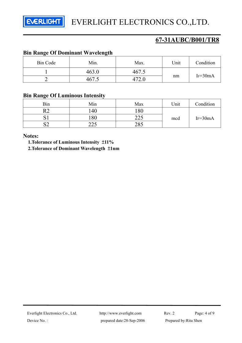
Bin Range Of Dominant Wavelength
Bin Code Min. Max. Unit Condition
1 463.0 467.5 2 467.5 472.0
nm IF=30mA
Bin Range Of Luminous Intensity
Bin Min Max Unit Condition R2 140 180 S1 180 225 S2 225 285
mcd IF=30mA
Notes:
1.Tolerance of Luminous Intensity ±11% 2.Tolerance of Dominant Wavelength ±1nm

EVERLIGHT ELECTRONICS CO.,LTD.
Everlight Electronics Co., Ltd. http://www.everlight.com Rev. 2 Page: 5 of 9
Device No. : prepared date:28-Sep-2006 Prepared by:Rita Shen
67-31AUBC/B001/TR8 Typical Electro-Optical Characteristics Curves Typical curve of spectral distribution: V(λ)=Standard eye response curve
0
50
100
400 450 500 550 600 650 700
Wp (nm)
Rel
ativ
e In
tens
ity (%
)
Blue V(λ)
Diagram characteristics of radiation :
70o
80o
60o
50o
40o
30o20o 10o
01.0
0o
0.6
0.2
0.4
0.8
1.0
View AngleRelative Intensity
View
Ang
le
Rel
ativ
e In
tens
ity
80o60o40o20o00.20.40.60.890o

EVERLIGHT ELECTRONICS CO.,LTD.
Everlight Electronics Co., Ltd. http://www.everlight.com Rev. 2 Page: 6 of 9
Device No. : prepared date:28-Sep-2006 Prepared by:Rita Shen
67-31AUBC/B001/TR8
Forward Current vs. Forward Voltage Ta=25℃
1
10
100
2.5 2.7 2.9 3.1 3.3 3.5 3.7 3.9
Forward Voltage VF (V)
For
war
d C
urre
nt I
F (
mA
)
Forward Current v.s. Ambient Temp.
0
10
20
30
40
0 20 40 60 80 100 120
T (degree C)
IF (
mA
)

EVERLIGHT ELECTRONICS CO.,LTD.
Everlight Electronics Co., Ltd. http://www.everlight.com Rev. 2 Page: 7 of 9
Device No. : prepared date:28-Sep-2006 Prepared by:Rita Shen
67-31AUBC/B001/TR8
Label explanation
CAT: Luminous Intensity Rank
HUE: Dom. Wavelength Rank
REF: Forward Voltage Rank
Reel Dimensions
Note: The tolerances unless mentioned is ±0.1mm,Unit = mm
RoHS
EVERLIGHT ELECTRONICS CO.,LTD.
Everlight Electronics Co., Ltd. http://www.everlight.com Rev. 2 Page: 8 of 9
Device No. : prepared date:28-Sep-2006 Prepared by:Rita Shen
67-31AUBC/B001/TR8
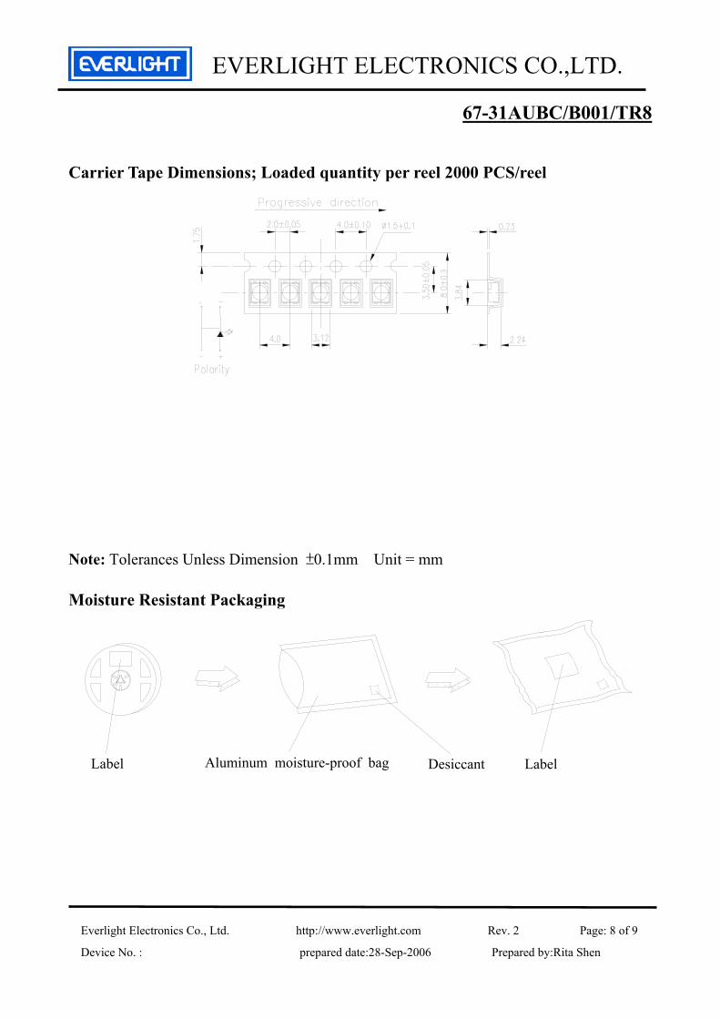
Carrier Tape Dimensions; Loaded quantity per reel 2000 PCS/reel
Note: Tolerances Unless Dimension ±0.1mm Unit = mm Moisture Resistant Packaging
Label Desiccant LabelAluminum moisture-proof bag

EVERLIGHT ELECTRONICS CO.,LTD.
Everlight Electronics Co., Ltd. http://www.everlight.com Rev. 2 Page: 9 of 9
Device No. : prepared date:28-Sep-2006 Prepared by:Rita Shen
67-31AUBC/B001/TR8 Precautions For Use 1. Over-current-proof
Customer must apply resistors for protection, otherwise slight voltage shift will cause big current change ( Burn out will happen ).
2. Storage 2.1 Do not open moisture proof bag before the products are ready to use.
2.2 Before opening the package: The LEDs should be kept at 30℃ or less and 90%RH or less.
2.3 After opening the package: The LED's floor life is 1 year under 30 deg C or less and 60% RH or less. If unused LEDs remain, it should be stored in moisture proof packages.
2.4 If the moisture absorbent material (silica gel) has faded away or the LEDs have exceeded the storage time, baking treatment should be performed using the following conditions. Baking treatment : 60±5℃ for 24 hours.
3. Soldering Condition 3.1 Pb-free solder temperature profile B. Recommend soldering pad
120 Sec. Max.
1~5 °C / Sec.Pre-heating 180~200°C
60 Sec. Max. Above 220°C
260°C. Max.10 Sec. Max.
1~5 °C / Sec.
3.2 Reflow soldering should not be done more than two times. 3.3 When soldering, do not put stress on the LEDs during heating. 3.4 After soldering, do not warp the circuit board. 4.Soldering Iron Each terminal is to go to the tip of soldering iron temperature less than 350℃ for 3 seconds within once in less than the soldering iron capacity 25W. Leave two seconds and more intervals, and do soldering of each terminal. Be careful because the damage of the product is often started at the time of the hand solder.